

Page 1

CommLink FXC-S201 User Guide
M4050-9900-200
1 October 2014
Page 2

Notices
Copyright & Trademark Notice
Copyright © 2012–2014, Grass Valley. All rights reserved.
Belden, Belden Sending All The Right Signals, and the Belden logo are trademarks or
egistered trademarks of Belden Inc. or its affiliated companies in the United States and
r
other jurisdictions. Grass Valley, CommLink FXC-S201 are trademarks or registered
trademarks of Grass Valley. Belden Inc., Grass Valley, and other parties may also have
trademark rights in other terms used herein.
Terms and Conditions
Please read the following terms and conditions carefully. By using CommLink FXC-S201
documentation, you agree to the following terms and conditions.
Grass Valley, a Belden Brand (“Grass Valley”) hereby
of CommLink FXC-S201 to use their product manuals for their own internal business use.
Manuals for Grass Valley products may not be reproduced or transmitted in any form or by
any means, electronic or mechanical, including photocopying and recording, for any
purpose unless specifically authorized in writing by Grass Valley.
A Grass Valley manual may have been revised to reflect changes made to the product
during its manufac
product. Care should be taken to ensure that one obtains the proper manual version for a
specific product serial number.
Information in this document is subject to change without
commitment on the part of Grass Valley.
Warranty information is available in the Support section of the Grass Valley Web site
(www.miranda.com).
turing life. Thus, different versions of a manual may exist for any given
grants permission and license to owners
notice and does not represent a
Title CommLink FXC-S201 User Guide
Part Number M4050-9900-200
Revision 1 October 2014
ii
Page 3

CommLink FXC-S201
1 About CommLink FXC-S201 . . . . . . . . . . . . . . . . . . . . . . . . . . . . . 1
About CommLink FXC-S201 . . . . . . . . . . . . . . . . . . . . . . . . . . . . . . . . . . . . . . . . . . . . . . . . . . . . . . . 2
About this User Guide . . . . . . . . . . . . . . . . . . . . . . . . . . . . . . . . . . . . . . . . . . . . . . . . . . . . . . . . . 2
Unpacking the CommLink FXC-S201 Fiber Optic Intercom Link . . . . . . . . . . . . . . . . . . . . . 3
Product Returns . . . . . . . . . . . . . . . . . . . . . . . . . . . . . . . . . . . . . . . . . . . . . . . . . . . . . . . . . . . . . . . 3
Ordering Information . . . . . . . . . . . . . . . . . . . . . . . . . . . . . . . . . . . . . . . . . . . . . . . . . . . . . . . . . . . . . 3
2 System Overview . . . . . . . . . . . . . . . . . . . . . . . . . . . . . . . . . . . . . . . 5
Fiber Overview . . . . . . . . . . . . . . . . . . . . . . . . . . . . . . . . . . . . . . . . . . . . . . . . . . . . . . . . . . . . . . . . . . . . 6
Wavelength-Division Multiplexing (WDM) . . . . . . . . . . . . . . . . . . . . . . . . . . . . . . . . . . . . . . . . . 6
CommLink FXC-S201 Front and Rear Panel Components. . . . . . . . . . . . . . . . . . . . . . . . . . . . 8
CommLink FXC-S201 Fiber Optic Intercom Link Front Panel. . . . . . . . . . . . . . . . . . . . . 8
Area A - System Configuration Switches . . . . . . . . . . . . . . . . . . . . . . . . . . . . . . . . . . . . . . . 8
Area B - Auto Null Operation . . . . . . . . . . . . . . . . . . . . . . . . . . . . . . . . . . . . . . . . . . . . . . . . . . 9
Area C - System Status Indicators . . . . . . . . . . . . . . . . . . . . . . . . . . . . . . . . . . . . . . . . . . . . . . 9
CommLink FXC-S201 Fiber Optic Intercom Link Back Panel . . . . . . . . . . . . . . . . . . . .10
CommLink FXC-S201 Fiber Optic Intercom Link Matrix and Station Connectors .12
Clear-Com Mode Wiring and Switch Settings . . . . . . . . . . . . . . . . . . . . . . . . . . . . . . . . . 12
RTS Mode Wiring and Switch Settings . . . . . . . . . . . . . . . . . . . . . . . . . . . . . . . . . . . . . . . . 13
CommLink FXC-S201 Fiber Optic Intercom Link Power Options . . . . . . . . . . . . . . . . . . . .14
CommLink FXC-S201 Fiber Optic Intercom Link Port State and Power Options. .15
FXC-S201 Power Connector - 4 Pin XLR Connector Wiring. . . . . . . . . . . . . . . . . . . . . .15
Fiber ADAP Power Supply . . . . . . . . . . . . . . . . . . . . . . . . . . . . . . . . . . . . . . . . . . . . . . . . . . . .16
User Guide
3 Setting Up the CommLink FXC-S201 . . . . . . . . . . . . . . . . . . . . 17
About Setting up the CommLink FXC-S201 . . . . . . . . . . . . . . . . . . . . . . . . . . . . . . . . . . . . . . . .18
Example CommLink FXC-S201Usage Scenarios . . . . . . . . . . . . . . . . . . . . . . . . . . . . . . . . . . . .19
Connecting a Two Channel Base System with Remote Belt Packs. . . . . . . . . . . . . . .19
Connecting a Matrix Frame System with Two Remote Matrix Stations . . . . . . . . . .20
Connecting a Matrix Frame with Remote Belt Packs . . . . . . . . . . . . . . . . . . . . . . . . . . .21
Connecting a Two Matrix Stations System . . . . . . . . . . . . . . . . . . . . . . . . . . . . . . . . . . . . .22
Converting a Two Channel System to work with a Matrix Frame. . . . . . . . . . . . . . . .23
CommLink FXC-S201 Configurations . . . . . . . . . . . . . . . . . . . . . . . . . . . . . . . . . . . . . . . . . . . . . .24
TWO-WIRE PARTYLINE MODE. . . . . . . . . . . . . . . . . . . . . . . . . . . . . . . . . . . . . . . . . . . . . . . . . 24
ADVANCED DSP AUTO-NULLING . . . . . . . . . . . . . . . . . . . . . . . . . . . . . . . . . . . . . . . . . . . . . 24
BELT PACK POWER . . . . . . . . . . . . . . . . . . . . . . . . . . . . . . . . . . . . . . . . . . . . . . . . . . . . . . . . . . . 24
FOUR-WIRE MATRIX MODE . . . . . . . . . . . . . . . . . . . . . . . . . . . . . . . . . . . . . . . . . . . . . . . . . . . 25
HYBRID MODE . . . . . . . . . . . . . . . . . . . . . . . . . . . . . . . . . . . . . . . . . . . . . . . . . . . . . . . . . . . . . . . 25
CommLink FXC-S201 Fiber Optic Intercom Link Switch Configuration . . . . . . . . . . . . . .26
4 CommLink FXC-S201 Operation . . . . . . . . . . . . . . . . . . . . . . . . 27
Using the Auto-Null Function . . . . . . . . . . . . . . . . . . . . . . . . . . . . . . . . . . . . . . . . . . . . . . . . . . . . .28
Best Practices . . . . . . . . . . . . . . . . . . . . . . . . . . . . . . . . . . . . . . . . . . . . . . . . . . . . . . . . . . . . . . . . . . . .29
Troubleshooting . . . . . . . . . . . . . . . . . . . . . . . . . . . . . . . . . . . . . . . . . . . . . . . . . . . . . . . . . . . . . . . . .29
1
Page 4

Notices
5 Specifications . . . . . . . . . . . . . . . . . . . . . . . . . . . . . . . . . . . . . . . . . 31
2
Page 5

About CommLink FXC-S201
This chapter provides an overview of the CommLink FXC-S201 Fiber Optic Intercom Link
and includes the safety and warranty information about it.
About CommLink FXC-S201 . . . . . . . . . . . . . . . . . . . . . . . . . . . . . . . . . . . . . . . . . . . . . . . . . . . . . . . . . . . 2
Unpacking the CommLink FXC-S201 Fiber Optic Intercom Link . . . . . . . . . . . . . . . . . . . . . . . . . 3
Ordering Information . . . . . . . . . . . . . . . . . . . . . . . . . . . . . . . . . . . . . . . . . . . . . . . . . . . . . . . . . . . . . . . . . 3
1
Page 6

About CommLink FXC-S201
About CommLink FXC-S201
About CommLink FXC-S201
CommLink™ FXC-S201 Intercom Link is a fiber-optic transceiver system that uses one or two
strands of fiber to carry two channels of production intercom, allowing robust voice and data
connectivity over distances up to 40KM (about 25 miles). The CommLink utilizes a dual-fiber
transceiver SFP, or a Wavelength Division Multiplexing (WDM) SFP for bidirectional signal
transmission on a single fiber strand. In the WDM scenario, all fiber links must consist of a
1310 nm unit at one end and a 1550 nm unit at the other.
Multiplexing (WDM) on page 6 for information about Wavelength-Division Multiplexing and
the use of CommLink units.
The CommLink is compatible with the industry's most popular intercom systems:
•Party line
•Clear-Com®
•RTS® TW
• Digital Matrix
• Clear-Com® MatrixPlus/Eclipse
•RTS® Adam/Cronus/Zeus
• Generic 4-Wire and Data
• Two Channels of bidirectional audio
• Two paths of bidirectional dataRS422 or RS485
See Wavelength-Division
In a special usage case, multi-strand fiber optic cable can be used for more than one signal one to the CommLink FXC-S201 and one carrying HD Video (see
S201Usage Scenarios on page 19).
About this User Guide
This User Guide is designed to cover all of the various options, so not every page in this
guide will apply to your specific system.
Example CommLink FXC-
2
Page 7

CommLink FXC-S201
User Guide
Unpacking the CommLink FXC-S201 Fiber Optic Intercom Link
Individual items shipped with a CommLink FXC-S201 system depend on the particular
configuration.
Please consult your packing slip and purchase ord
the expected components. Inspect all components for scratches and other mechanical
damage, and inspect the electrical connectors for bent or damaged pins and latches.
Report any missing or damaged components to Grass Valley. See Product Returns on
page 3.
You must use your own video and audio cables to make connections for Video, Tally, Black
t/Genlock, Base Station monitor, intercom, and other ancillary signals and equipment.
Burs
Suggestions for these cables are discussed later in this User Guide.
Product Returns
In the unlikely event of damage to your CommLink FXC-S201 Fiber Optic Intercom Link
during shipping or delivery, take note of any damage with the delivery or shipping service.
If any component does not work correctly out of the box, contact Grass Valley (see Contact
page 33).
Us on
If the problem cannot be remedied through a service telephone, you will receive an RMA
number (Return of Mer
outside of all shipping boxes and on all documentation provided with the items to be
returned.
Ordering Information
er to ensure that you have received all of
chandise Authorization). Take note this RMA number inside and
Part Number Description
FXC-S201-W13 Commlink, Standalone, WDM,
FXC-S201-W15 Commlink, Standalone, WDM,
FXC-S201-S13 Commlink, Standalone, 1310 nm, dual fiber
ADAP-AC-04 AC Power Adapter; 120/240 VAC in; 4-pin XLR; 4A; 15 VDC out
1310 nm, 1 fiber
1550 nm, 1 fiber
3
Page 8

About CommLink FXC-S201
Product Returns
4
Page 9

System Overview
This chapter presents an overview of the CommLink FXC-S201 Fiber Optic Intercom Link
componenets and options.
Fiber Overview . . . . . . . . . . . . . . . . . . . . . . . . . . . . . . . . . . . . . . . . . . . . . . . . . . . . . . . . . . . . . . . . . . . . . . . . 6
Wavelength-Division Multiplexing (WDM) . . . . . . . . . . . . . . . . . . . . . . . . . . . . . . . . . . . . . . . . . . . . . 6
CommLink FXC-S201 Front and Rear Panel Components . . . . . . . . . . . . . . . . . . . . . . . . . . . . . . . 8
CommLink FXC-S201 Fiber Optic Intercom Link Power Options . . . . . . . . . . . . . . . . . . . . . . . . 14
5
Page 10
System Overview
Fiber Overview
Fiber Overview
Fiber Optics and Fiber Optic Cable are at the heart of the CommLink FXC-S201 Fiber Optic
Intercom Link Fiber Optic Intercom Link System. The Commlink system features the ability
to multiplex and de-multiplex a variety of video, audio, and data signals so that they can be
carried over a thin strand of Fiber Optic cable for long distances.
The specific theory and operation of Fiber Optics is beyond the scope of this document, but
you need to be aware of the different types of Fiber Optic Cable and Fiber Optic Cable
Connectors. Most CommLink FXC-S201 Fiber Optic Intercom Link applications will use
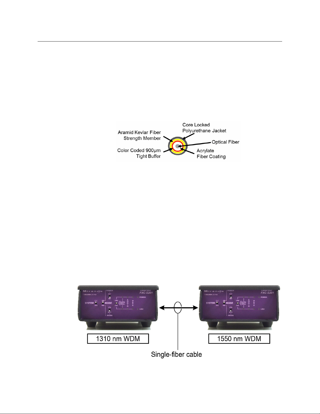
Single Mode Fiber with ST Connectors.
Fig. 2-1: Single Mode Fiber Optic Cable Cross-Section
Wavelength-Division Multiplexing (WDM)
Fiber optic communication is enhanced by the use of Wavelength-Division Multiplexing
(WDM). With WDM, multiple optical carrier signals can be carried on a single optical fiber by
using different wavelengths of laser light for each carrier. The full theory of WDM is beyond
the scope of this manual, but it is important to understand that by using equipment with
different transmitter wavelengths on opposite ends of a fiber optic cable, signals can be
sent in both directions over that single cable.
CommLink FXC-S201 units intended for WDM u
wavelengths of 1310 nm and 1550 nm, and a WDM link requires one of each, as illustrated
in Figure 2-2.
Two units with the same transmit wavelength will not work for WDM operation over a
-fiber cable.
single
se are available with transmitter
Fig. 2-2: Pairing Different WDM Factor CommLink Units
6
Page 11
CommLink FXC-S201
User Guide
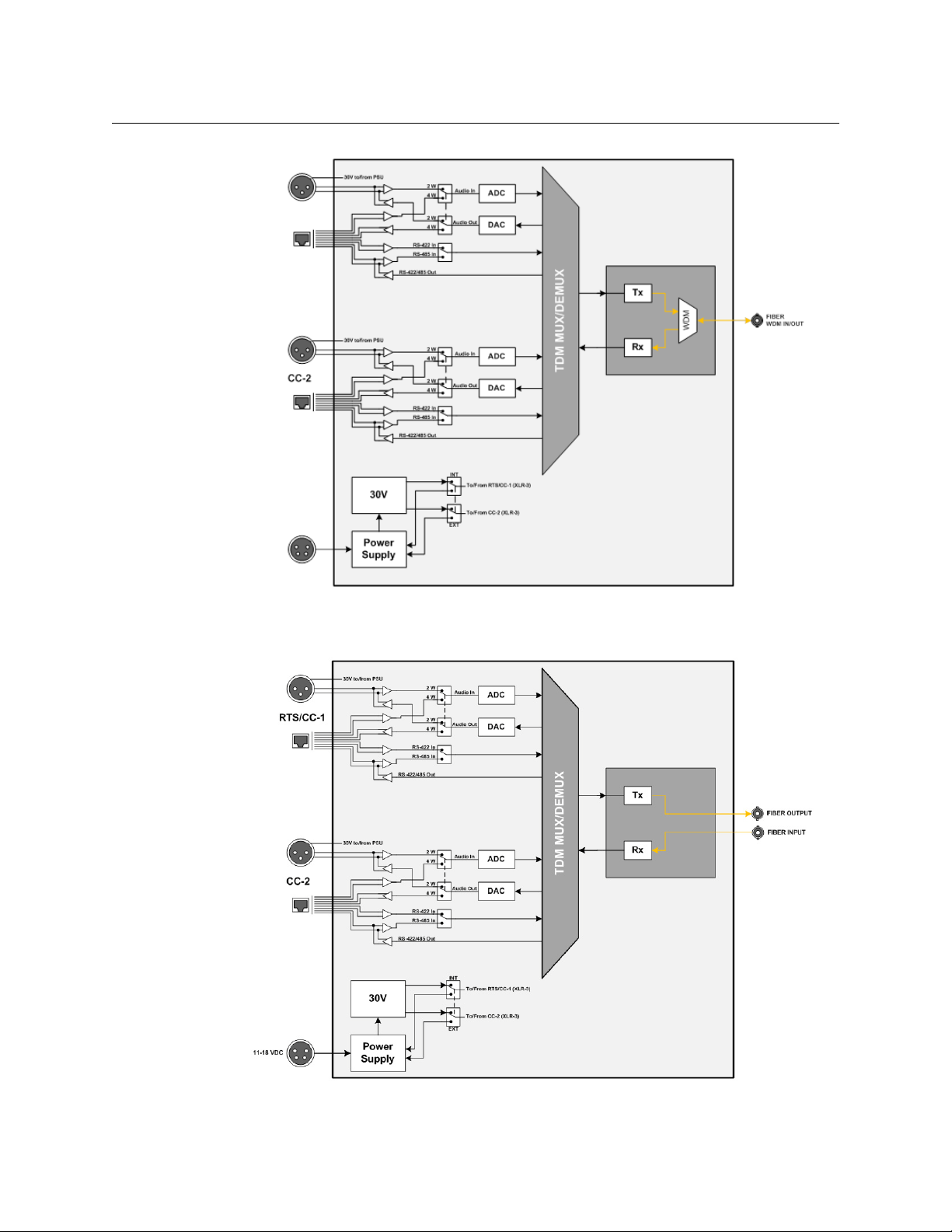
Fig. 2-3: FXC-S201 Block Diagram - WDM Version
Fig. 2-4: FXC-S201 Block Diagram - Dual Fiber Version
7
Page 12
System Overview
CommLink FXC-S201 Front and Rear Panel Components
CommLink FXC-S201 Front and Rear Panel Components
CommLink FXC-S201 Fiber Optic Intercom Link Front Panel
Fig. 2-5: CommLink FXC-S201 Fiber Optic Intercom Link Front Panel
The CommLink FXC-S201 Fiber Optic Intercom Link has three features:
• Area A: System Configuration Switches
• Area B: Auto Null Control and Indicators
• Area C: System Status Indicators
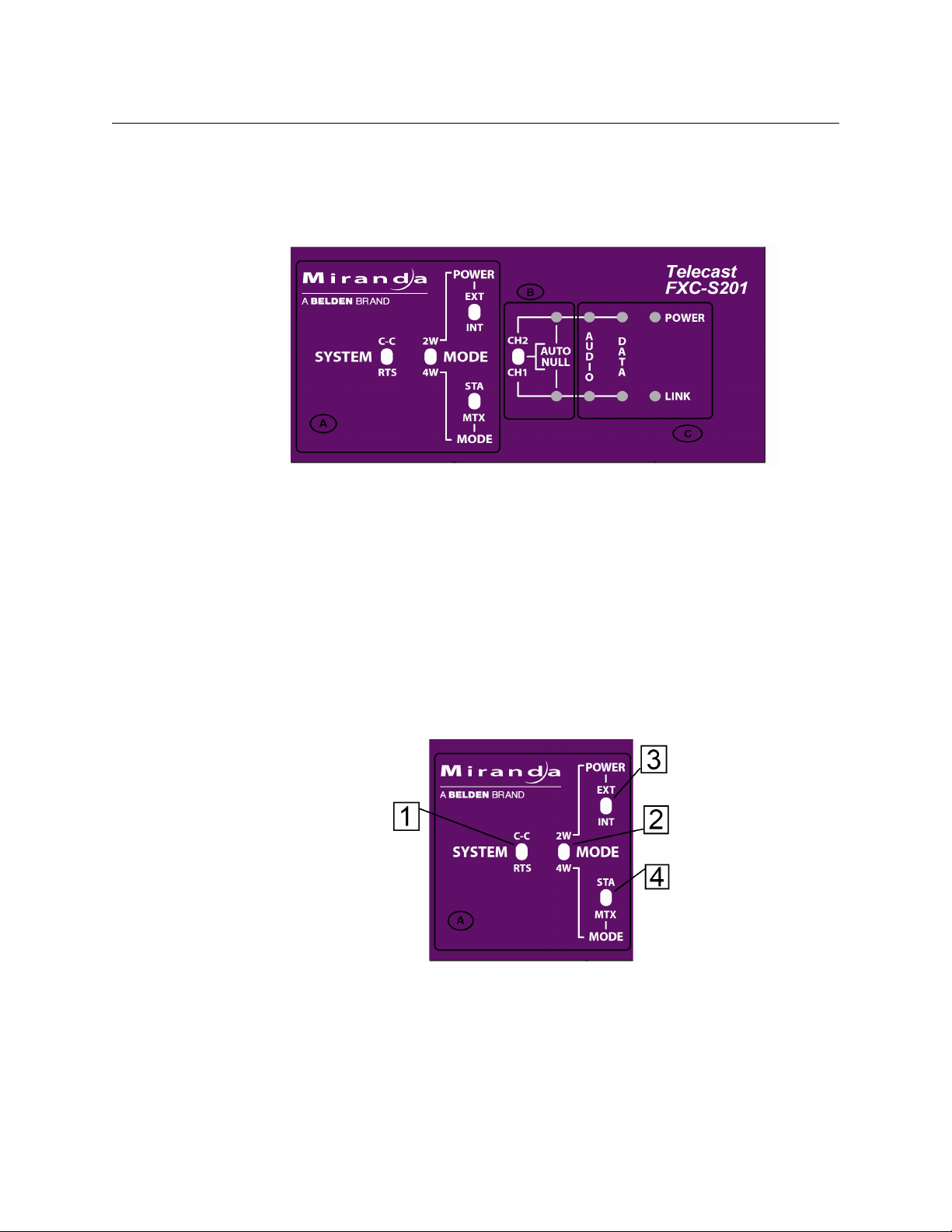
Area A - System Configuration Switches
The four switches in this section allow the configuration of the CommLink FXC-S201 Fiber
Optic Intercom Link for the particular intercom environment in use. See Example
CommLink FXC-S201Usage Scenarios on
switches interact.
Fig. 2-6: System Configuration switches
• 1: System Switch - sets the CommLink FXC-S201 Fiber Optic Intercom Link in either RTS
mode or Clear-Com (C-C) mode
• 2: Mode Switch - sets the CommLink FXC-S201 Fiber Optic Intercom Link in either Two
W
ire (2W) or Four Wire (4W) mode
page 19 below for examples of how these
8
Page 13

CommLink FXC-S201
User Guide
• 3: 2W Power Switch - sets the CommLink FXC-S201 power mode to either externally
powered (EXT) or internally powered (INT). This switch is only operational when the
Mode Switch is set to 2W.
• 4: 4W Mode Switch - sets the CommLink FXC-S201 to run in Station (STA) mode or
M
atrix (MTX) mode. This switch is only operational when the Mode Switch is in 4W
mode.
When connecting two CommLink FXC-S201 Fiber Optic Intercom Link units via fiber cable,
ommLink FXC-S201 unit must be independently set for the configuration
each C
requirements at that end of the fiber link.
Area B - Auto Null Operation
Fig. 2-7: Auto Null switch and indicator
Please see Using the Auto-Null Function on page 28 below on the Auto Null function.
• 5: Auto Null switch: this three-position spring-loaded momentary switch activates the
Auto Null process for either Channel 1 (CH1) or Channel 2 (CH2).
• 6: Channel 1 Auto Null Activity Indicator: blinks Gr
een while the Nulling process occurs.
• This indicator will be a solid Green to indicate the process is complete and good.
• This indicator will be Red if there was a problem with the null. (see Using the Auto-
Null Function on
page 28 for more information)
• 7: Channel 2 Auto Null Activity Indicator: behaves the same as the Ch1 Auto Null
activity indicator
Area C - System Status Indicators
• 8: Audio Activity Indicator
Fig. 2-8: System Status Indicators
9
Page 14

System Overview
CommLink FXC-S201 Fiber Optic Intercom Link Back Panel
• Green when audio activity is below 0 db
• Red when audio activity is above 0 db
• 9: Data Activity Indicator
• Green when there is data activity on the particular channel
•10: Power Indicator
• Green indicates power
•11: Link Status Indicator
• Green indicates link is good
• Red indicates link is bad or non-existent.
CommLink FXC-S201 Fiber Optic Intercom Link Back Panel
10
Fig. 2-9: CommLink FXC-S201 Back Panel
1 11-18 VDC Power Connector - for use with the ADAP-AC-04 Power Supply.
This power supply has a 4-pin XLR connector. See CommLink FXC-S201 Fiber Optic
Intercom Link Port State and Power Options on
2 RT
S/CC-1 Chassis Mounted XLR Connector - for RTS TW operation or Channel 1 of
page 15 for wiring information.
Clear-Com two wire operation
3 C
C-2 Chassis Mounted XLR Connector - for Channel 2 of Clear-Com two wire
operation. Not active when the system is in RTS-TW mode.
Connectors 4 and 5 operate in one of 4 modes, depending on system configuration.
These connec
tors can be used with RJ45 cables or RJ11 cables. See CommLink FXC-
S201 Fiber Optic Intercom Link Matrix and Station Connectors on page 12 for more
information and for wiring information.
-CH1 Connector - 8 Conductor RJ45/RJ11 connector for Channel 1 in 4-wire
4 4W
operation.
Page 15

CommLink FXC-S201
User Guide
5 4W-CH2 Connector - 8 Conductor RJ45/RJ11 connector for Channel 2 in 4-wire
operation.
6 Fiber Input (WDM I/O)- ST Connector for Fiber Optic Cable. Connect the input fiber in
a two-fiber system. Connect the single fiber cable here for WDM operation.
7 Fiber Output - ST Connector for Fiber Optic Cable. Connect the output fiber in a two-
fiber system. There is no connection here for WDM operation.
Read the Using Fiber Optics Guide for information on how to manage and deploy your
fiber optics cabling, safety precautions, tips & tricks, and recommendations for creating
complex fiber optic networks. You can find a copy of this document on the Support
portal (see
Contact Us on page 33).
11
Page 16

System Overview
CommLink FXC-S201 Fiber Optic Intercom Link Matrix and Station Connectors
CommLink FXC-S201 Fiber Optic Intercom Link Matrix and Station
Connectors
Both the RTS and Clear-Com system matrix systems use data wiring to carry intercom audio
and data. Clear-Com systems use an 8-wire "network" cable with RJ45 connectors. RTS
systems use a 6-wire cable with RJ11 connectors similar to standard telephone wiring.
However, telephone wiring will not work as it is only 4-wire.
The CommLink FXC-S201 Fiber Optic Intercom Link Configuration is shown for each
intercom mode. The switch position is indicated. In all cases, the 4W/2W switch is in the 4W
position.
Clear-Com Mode Wiring and Switch Settings
Signal Pin # Signal Pin #
RS-422 data receive (+) 1 RS-422 data send (+) 1
RS-422 data receive (–) 2 RS-422 data send (–) 2
Audio receive (+) 3 Audio send (+) 3
Audio send (+) 4 Audio receive (+) 4
Audio send (–) 5 Audio receive (–) 5
Audio receive (–) 6 Audio send (–) 6
RS-422 data send (+) 7 RS-422 data receive (+) 7
RS-422 data send (–) 8 RS-422 data receive (–) 8
To Remote Station To Matrix Frame
Fig. 2-10: Clear-Com Mode - Switch Settings and 4W Data Connector Pinouts
12
Page 17

CommLink FXC-S201
RTS Mode Wiring and Switch Settings
In all cases the 4W/2W switch is in the 4W position.
Signal Pin # Signal Pin #
N/C 1 N/C 1
Data – 2 RS485 Data – 2
Audio Out (MTX –>SAT) (+) 3 Audio In (MTX –>STA) (+) 3
Audio In (STA –>MTX) (+) 4 Audio Out (SAT–> MTX) (+) 4
Audio to Matrix (–) 5 Audio Out (SAT–> MTX) (–) 5
Audio from Matrix (–) 6 Audio In (MTX –>STA) (–) 6
Data + 7 RS485 Data + 7
N/C 8 N/C 8
User Guide
To Remote Station To Matrix Frame
Fig. 2-11: RTS Mode - Switch Settings & 4W Data Connector Pinouts
13
Page 18

System Overview
CommLink FXC-S201 Fiber Optic Intercom Link Power Options
CommLink FXC-S201 Fiber Optic Intercom Link Power Options
The CommLink FXC-S201 Fiber Optic Intercom Link is powered through an attached
external power supply or from power received from the Two-Wire intercom connection.
The following table shows how a CommLink FXC-S201 F
iber Optic Intercom Link unit can
be powered:
12 Volt Power
Model
FXC-S201-W13
FXC-S201-W15
FXC-S201-S13
Supply
ADAP-AC-04
with 4-pin XLR
30 Volt Power Supply
Can be powered from
I
ntercom system when
in Two-Wire mode
* 30 Volts is output from the CommLink FXC-S2
01 unit when it has 12V power applied.
30 Volt Power Output
to Belt Packs*
30 Volts is provided on
S/CC-1 and CC-2
RT
XLR connectors.
When no 12V power is applied (2W Power switch is on EXT), the CommLink FXC-S201 Fiber
Optic Intercom Link unit derives power from the intercom connection and all Belt-Packs
derive power from the Intercom system or from internal power sources.
When powered by the 12 Volt power supply, the CommLink FXC-S201 Fiber Optic Intercom
will power five intercom belt packs (10 total on the system) or two remote matrix
Link
stations per channel. If the system has self-powered belt packs attached (30V ), and the
external 12 Volt power supply is also attached, the 12 Volt supply takes priority in powering
the CommLink FXC-S201unit.
14
Page 19

CommLink FXC-S201
CommLink FXC-S201 Fiber Optic Intercom Link Port State and Power Options
The CommLink FXC-S201 Fiber Optic Intercom Link also manages the enabling of ports
depending on the type of power supply and the system mode. The following table shows
the different CommLink FXC-S201 Fiber Optic Intercom Link states:
Internal 30 Volt
System Mode Power Supply
Supply
Belt Pack Power 4W Ports
User Guide
2W 30V from Intercom System Disabled Self-powered or from
Intercom System
2W 12 Volt External & Belt-Packs
ar
e powered internally or
from the intercom system
2W 12 Volt External Enabled From CommLink Disabled
4W 12 Volt External Disabled Disabled Enabled
2W to 4W or
o 2W
4W t
Conversion
12 Volt External Can be used Self-powered or from
Disabled Self-powered or from
Intercom System
tercom System or
In
from CommLink FXCS201 Fiber Optic
Intercom Link 30V
supply
FXC-S201 Power Connector - 4 Pin XLR Connector Wiring
Pin Function
1 Ground
2 Unused
3 Unused
Disabled
Disabled
Enabled but
with
/485
RS422
data transfer
disabled
4 + Power 12 VDC
This matching connector is from either an AD
power supply.
AP-AC-04 or a customer-supplied 12VDC
15
Page 20

System Overview
Fiber Part Number ADAP-AC-04
Supplied with 4PIN XLR/A4F connector for power plug on FXC-S201 unit
Fiber ADAP Power Supply
Fiber ADAP Power Supply
Fig. 2-12: Power Supply
16
Page 21

Setting Up the CommLink FXC-S201
This chapter explains how to set up and configure the CommLink FXC-S201 Fiber Optic
Intercom Link system.
About Setting up the CommLink FXC-S201 . . . . . . . . . . . . . . . . . . . . . . . . . . . . . . . . . . . . . . . . . . . . 18
CommLink FXC-S201 Configurations . . . . . . . . . . . . . . . . . . . . . . . . . . . . . . . . . . . . . . . . . . . . . . . . . 24
CommLink FXC-S201 Fiber Optic Intercom Link Switch Configuration . . . . . . . . . . . . . . . . . 26
17
Page 22

Setting Up the CommLink FXC-S201
About Setting up the CommLink FXC-S201
About Setting up the CommLink FXC-S201
Use of the CommLink FXC-S201 Fiber Optic Intercom Link system first requires the setup
and connection of the Intercom System and the CommLink FXC-S201 units. The second
step is the proper configuration or setting of switches on the CommLink FXC-S201 front
panel. If two-wire systems are in use, the Auto Null function should be employed.
Each system setup is based on the appropriate mix of the three physical types of the
CommLink FXC-S201 Fiber Optic Intercom Link. Depending on your particular operation
the combination of units may be all the same physical type or a mix and match. Whatever
the physical configuration of the units, the single-fiber solution requires a 1310mm WDM
and 1550mm WDM pair. It makes no difference where the WDM units are placed in the
system. If the CommLink FXC-S201 Fiber Optic Intercom Link is being used locally to
convert between intercom system types, either WDM type can be used
18
Page 23

CommLink FXC-S201
Example CommLink FXC-S201Usage Scenarios
Five usage configurations are illustrated:
• Connecting a Two Channel Base System with Remote Belt Packs
• Connecting a Matrix Frame System with Two Remote Matrix Stations
• Connecting a Matrix Frame with Remote Belt Packs
• Connecting Two Matrix Stations System with a
to a Multi-Strand Fiber Cable (This is an example of "hybrid" use with the CommLink
FXC-S201 Fiber Optic Intercom Link)
• Converting a Two Channel System to work with a Matrix Frame
Connecting a Two Channel Base System with Remote Belt Packs
Matrix Frame with Video Multiplexed on
User Guide
Fig. 3-1: Connecting a Two Channel Base System with Remote Belt Packs
Connect the Two-Channel Two-Wire Intercom System (1) and CommLink FXC-S201 Fiber
Optic Intercom Link Unit "A" (2). In this example it is assumed that the CommLink FXC-S201
Fiber Optic Intercom Link is powered from the intercom. Run a Single Strand Fiber Cable
(3) between CommLink FXC-S201 Fiber Optic Intercom Link Unit "B" (4) and power the
CommLink FXC-S201 Fiber Optic Intercom Link using the appropriate power supply (5).
Connect your intercom Belt Packs in normal daisy chain fashion
Fiber Optic Intercom Link. The number of Belt Packs will depend on whether they are selfpowered or are powered by the CommLink FXC-S201 Fiber Optic Intercom Link. When
powered by the CommLink FXC-S201 Fiber Optic Intercom Link you can expect 5 units to
work per channel.
Remember that CommLink FXC-S201 Fiber Optic Intercom Link "A" must have a WDM factor
fferent from CommLink FXC-S201 Fiber Optic Intercom Link "B." You must use a WDM
di
@1550nm unit at one end of the fiber cable and a WDM@1310nm at the other end of the
fiber cable.
to the CommLink FXC-S201
19
Page 24

Setting Up the CommLink FXC-S201
Connecting a Matrix Frame System with Two Remote Matrix Stations
FXC-S201 Unit System Switch Mode Switch 4W Switch 2W Power Switch
#A in drawing Match Intercom 2W NA EXT
#B in drawing Match Intercom 2W NA INT
Connecting a Matrix Frame System with Two Remote Matrix Stations
Fig. 3-2: Connecting a Matrix Frame System with Two Remote Matrix Stations
Connect the Intercom Matrix (1) and CommLink FXC-S201 Fiber Optic Intercom Link Unit
"A" (2). Run a Single Strand Fiber Cable, or dual cable if used (3) between CommLink FXCS201 Fiber Optic Intercom Link Unit "B" (4) and power the CommLink FXC-S201 Fiber Optic
Intercom Link using the appropriate power supply (5).
Connect your two intercom Matrix Stations (6) and pr
ovide power locally. Remember that
CommLink FXC-S201 Fiber Optic Intercom Link "A" must have a WDM factor different from
CommLink FXC-S201 Fiber Optic Intercom Link "B." You must use a WDM @1550nm unit at
one end of the fiber cable and a WDM@1310 at the other end of the fiber cable.
FXC-S201 Unit System Switch Mode Switch 4W Switch 2W Power Switch
#A in drawing Match Intercom 4W MTX NA
#B in drawing Match Intercom 4W STA NA
20
Page 25

Connecting a Matrix Frame with Remote Belt Packs
Fig. 3-3: Connecting a Matrix Frame with Remote Belt Packs
Connect the Intercom Matrix (1) and CommLink FXC-S201 Unit "A" (2). Run a Fiber Cable
(single or dual strand, as required) (3) between CommLink FXC-S201 Units “A” (2) and "B" (4)
and power the CommLink FXC-S201 using the appropriate power supply (5).
CommLink FXC-S201
User Guide
Connect your intercom Belt Packs in normal daisy chain fashion to the CommLink FXC-
01. The number of Belt Packs will depend on whether they are self-powered or are
S2
powered by the CommLink FXC-S201. When powered by the CommLink FXC-S201, you can
expect 5 units to work per channel depending on cable runs
Remember that for a single-fiber solution, C
ommLink FXC-S201 Fiber Optic Intercom Links
"A" and “B” must have different WDM factors. You must use a WDM @1550nm unit at one
end of the fiber cable and a WDM@1310 at the other end of the fiber cable.
FXC-S201 Unit System Switch Mode Switch 4W Switch 2W Power Switch
#A in drawing Match Intercom 4W MTX NA
#B in drawing Match Intercom 2W NA INT
21
Page 26

Setting Up the CommLink FXC-S201
Connecting a Two Matrix Stations System
Connecting a Two Matrix Stations System
Fig. 3-4: Connecting Two Matrix Stations System with a Matrix Frame plus Video Multiplexed on the
Multi-Strand Fiber Cable
This usage scenario demonstrates the flexibility provided by Grass Valley products. In this
case a multi-strand fiber cable with MX connectors is used in place of the single strand fiber
cable. With the addition of the Break Out cable MXRR-4-08, fiber optic signals can be sent to
multiple locations. Here a Grass Valley Rattler Mini HD/SDI Transmitter and Receiver are
used to transmit HD video along the same fiber cable as the Intercom Link. A wide variety
of set-ups are possible using different components. Please consult your Grass Valley dealer
for more information.
The example calls for you to connect the Matrix S
tations (1) and CommLink FXC-S201 unit
"A" (2). Connect the CommLink FXC-S201 unit to the Break-Out Cable (3) and then connect
the Break-Out cable to the multi-strand fiber cable (5). Connect the Rattler Receive Unit RRX
1679 (4) to your HD Video Display and to the Break Out Cable (3).
Connect the Fiber Cable (5) to a Break Out Cable (6) at the other end. The Break Out Cable
onnects to CommLink FXC-S201 unit "B" (8) and to the Rattler Transmit Unit RTX 1660
then c
(7). The Rattler is connected to your HD video source and the CommLink FXC-S201 is
connected to the Intercom Matrix Frame (9).
22
Page 27

Converting a Two Channel System to work with a Matrix Frame
Fig. 3-5: Converting a Two Channel System to work with a Matrix Frame
Connect the Two-Channel Two-Wire Intercom System (1) and CommLink FXC-S201 Fiber
Optic Intercom Link Unit (2). Power the CommLink FXC-S201 using the appropriate power
supply (3).
Connect the Intercom Matrix (4).
Note that no fiber is used in this scenario; the single FXC-S201 acts as a format converter.
The System Switches should be set as follows:
• SYSTEM - Set for your Two Channel System - ClearCom (CC) or RTS
• MODE - Set to 2W
• 2W POWER - Set for your CommLink Unit
CommLink FXC-S201
User Guide
23
Page 28

Setting Up the CommLink FXC-S201
CommLink FXC-S201 Configurations
CommLink FXC-S201 Configurations
The CommLink™ FXC-S201 Intercom Link comes in three different models, based on the SFP
transceiver that is incorporated:
•dual-fiber transceiver;
• single fiber WDM 1310 nm transceiver,
• single-fiber WDM 1550 nm transceiver.
All models are supplied in a MiniMussel Shel
environments.
Please see Ordering Information on
Fig. 3-6: CommLink FXC-S201 Fiber Optic Intercom Link Physical Configuration
The system provides flexibility in the types of intercom systems that can be used, in that the
system can link one type of party line system to another type of party line system, a matrix
frame to two key panels, or act as a two-wire to four-wire hybrid adaptor via fiber or as a
stand-alone local unit. Each of these operating modes is explained in detail later in this
document.
page 3.
l enclosure suitable for use in harsh
24
TWO-WIRE PARTYLINE MODE
Plug two channels of Clear-Com® PL (two XLRs) or RTS® TW (one XLR) into each CommLink
module and connect them with a fiber cable. The system will "translate" between two
systems so that you can have Clear-Com® at one end and RTS® at the other. It also translates
the call lights.
ADVANCED DSP AUTO-NULLING
Once the two-party system is connected, a toggle of the AUTO NULL switch provides a digital
system null of the two-wire system, no matter what the load, without the need for manual
adjustments.
BELT PACK POWER
Each CommLink™ module can be powered from the Party line intercom circuit without an
external power supply, like a belt pack. Alternately, with a 12VDC power source, the
CommLink unit can act as a Party line power supply, providing enough 30VDC current to
support approximately ten belt packs.
Page 29

CommLink FXC-S201
User Guide
FOUR-WIRE MATRIX MODE
The system links a MatrixPlus/Eclipse (Clear-Com®) or Adam (RTS®) family matrix frame and
two of the system's key panels over a fiber strand. All of the key panel functionality is
supported, including displays, controls, and communications to the matrix frame.
HYBRID MODE
The CommLink system can be used to connect a matrix frame in a control room or truck with
two party line channels in the venue, without the need for a separate hybrid adaptor.
A single CommLink unit can also act as a standalone digital system interface/system-tosystem adapter, utilizing the digital auto-nulling system. Connect two-wire intercom
systems to legacy fiber systems, two-way radios, satellite links, TV cameras, and other
communications devices with 4-wire circuits.
25
Page 30

Setting Up the CommLink FXC-S201
CommLink FXC-S201 Fiber Optic Intercom Link Switch Configuration
CommLink FXC-S201 Fiber Optic Intercom Link Switch
Configuration
The following decision tree traces the setting of the CommLink FXC-S201 Fiber Optic
Intercom Link configuration switches.
• Set the System mode - Clear-Com (CC) or RTS
• Decide if you are operating in 2W or 4W
• If in 2W set your power to External (EXT) or Int
the power from the intercom system or Belt Packs (EXT) or providing internal power
from the CommLink FXC-S201 Fiber Optic Intercom Link with the 12 Volt power supply
(INT)
• If in 4W set the switch depending on whether y
(STA) or Matrix (MTX) attached to the CommLink FXC-S201 Fiber Optic Intercom Link
ernal (INT) - this decides between using
ou have an Intercom Matrix Station
26
Fig. 3-7: Configuration Switch Decision Tree
Page 31

CommLink FXC-S201 Operation
This chapter describes the operation of CommLink FXC-S201 Fiber Optic Intercom Link.
Please keep in mind that once the system is properly set up and configured there is very
little to do during normal operation.
Using the Auto-Null Function . . . . . . . . . . . . . . . . . . . . . . . . . . . . . . . . . . . . . . . . . . . . . . . . . . . . . . . . . 28
Best Practices . . . . . . . . . . . . . . . . . . . . . . . . . . . . . . . . . . . . . . . . . . . . . . . . . . . . . . . . . . . . . . . . . . . . . . . . 29
Troubleshooting . . . . . . . . . . . . . . . . . . . . . . . . . . . . . . . . . . . . . . . . . . . . . . . . . . . . . . . . . . . . . . . . . . . . . 29
27
Page 32

CommLink FXC-S201 Operation
Using the Auto-Null Function
Using the Auto-Null Function
The Auto-Null function is used only with CommLink FXC-S201 Fiber Optic Intercom Link
units that are connected to Two-Wire system. Auto Null has no purpose with a Four Wire
system.
To use the Auto-Null Function
1 Before starting the Auto-Null process, ensure the following:
• A: All headsets are connected
• B: Headsets are not being worn by any operators
• C: Headset microphones are off
2 To Auto Null Channel 1 (CH1), hold the Auto Null switch (A) in the direction of CH1.
The system will generate a tone and the indicator (B) will blink green while the Nulling
process occurs. This should take about 7.5 seconds.
3 Once the Auto Null process is complete, the tone will stop and the indicator will glow
green.
This indicator will be red if there was a problem with the null. This can occur if any of
the items in Step 1 are not followed.
4 Once you troubleshoot the Null problem, perform Steps 1-3 again.
5 For Channel 2 (CH2), hold the Auto Null switch (A) in the direction of CH2. Steps 2 and 3
will then follow with the CH2 indicator being active (C).
6 After completing the Auto-Null process, check that side-tone operation and overall
intercom performance on each intercom channel is correct.
28
Page 33

Best Practices
• Take every precaution to reduce the risk of damaging your eyes when handling the
equipment.
• Protect the Fiber Optic Cable and the Fiber Optic Connectors. Always keep these
capped unless they are being connected.
• Once the system is set up and running, carefully monitor the Link strength indicators at
either of the CommLink FXC-S201 Fiber Optic Intercom Link units. Because the system
is digital, the Signal Strength must either meet or exceed the operational requirements.
When the Signal Strength is no longer strong enough, the signal stops.
• If introducing new equipment (intercom units, additional Belt-Packs, etc.) or new
operators, be sure to do a comprehensive, realistic test run. A hands-on approach is the
best way to understand how the system should work and what to do to ensure proper
operation.
• Be as careful during System tear down as during System setup.
Troubleshooting
CommLink FXC-S201
User Guide
Troubleshooting any technical issues with the CommLink FXC-S201 Fiber Optic Intercom
Link System is similar to any piece of television production gear, with the exception of the
core Fiber Optic technology.
The following is a list of checks to keep in mind:
• During power-up of the CommLink FXC-S201 Fiber Optic Intercom Link, the Auto Null
indicators will turn Green, then Red, and then OFF. This indicates that these LEDs are
working properly. These are the only indicators tested on power up.
• The Auto Null indicators will blink RED if any of the CommLink FXC-S201 Fiber Optic
Intercom Link operating power levels are out of specification. This error condition will
not likely affect operation, but it should be addressed as soon as possible. This error
may require contacting Grass Valley Support (see
• Check all your cables for any broken connections or bad connectors.
• Check that your Power Supplies are working.
• If there is a power problem, check the fuses.
• If you cannot resolve the problem in the field, contact Grass Valley Fiber support (see
Contact Us on page 33)
Contact Us on page 33).
29
Page 34

CommLink FXC-S201 Operation
Troubleshooting
30
Page 35

Specifications
Intercom
Number of intercom channels................................................................................................. 2
2-Wire (TW/PL)
Interface:...........................................................................................Clear-Com PL: XLR3M x 2
..........................................................................................................................RTS TW: XLR3M x 1
Max Level.......................................................... 2VP-P, @ 1KHz (equiv. to +18dBu in 4W)‡
Dyn. Range................................................................................... >85dB, ref. 2VP-P @ 1KHz ‡
Freq. Response ........................................................+.1/-3dB, 70Hz to 22kHz, ref. 2VP-P ‡
THD+N............................................................................................................... <0.1% @ 2VP-P ‡
I/O Impedance (100Hz to 20KHz):
Termination engaged (internal power) ....................................................220 ±10%
Termination dis-engaged (external power) 10K
Nulling: ................................................................................................................ Automatic DSP
‡properly terminated (internal or external)
4-Wire (4W) Ports
Interface ................................................................ Clear-Com MatrixPlus/Eclipse: RJ45 x 2
..............................................................................................RTS Adam/Cronus/Zeus: RJ11 x 2
Maximum Level (I/O, Unity Gain) ............................................................................+18dBu
Dynamic Range ....................................................................................... >85dB, ref. +18dBu
Frequency Response.................................................... +.1/-3dB, 35Hz-22kHz, ref. 0dBu
THD+N.......................................................................................... <0.05% @ +17dBu @ 1KHz
Input Impedance. ...........................................................................................10k balanced
Output Impedance.... ...................................................................................... 30 balanced
Data: . ....................................................................................Clear-Com: RS422, RTS: RS485
Crosstalk: . .......................................................................................................................... >85dB
Electro-Optical
Operating Wavelength, standard .............1310/1550 nm (WDM) or 1310 dual fiber
Nominal Optical Loss Budget Values:
TX Laser output power........................................................................................... .-7 dBm
RX Sensitivity, HD/SDI............................................................................................-22 dBm
Link/Distance Limit* .................................................................. 15dB optical loss (40Km*)
Fiber Compatibility... ............................................................................................ Single Mode
Optical Connector .....................................................................................................................ST
*Maximum cable length varies due to optical cable quality, dirt/dust/contamination on
connectors, and the number of in-line connectors.
31
Page 36

Specifications
Mechanical/Environmental
Dimensions (HxWxL) (no feet on case)............................................................ 2" x 4" x 10"
Weight ......................................................................................................................................2.8 lb
Power Consumption
2W with Local Power ...................................................................... 3 watts@10-18VDC
Powered from 2W System............................................................. 6 watts@10-18VDC
4W System .......................................................................................... 3 watts@10-18VDC
Temperature Range .............................................................................................-25° to +55°C
Humidity Range .................................................................. 0 to 95% RH, Non-condensing
Compliance
Laser Safety...............................................................................Class 1 Laser 21 CFR 1040.10
EMI/RFI..................................................................................................................IEC/EN 60825-1
RoHS
32
Page 37

Grass Valley Technical Support
For technical assistance, please contact the Grass Valley Technical Support center nearest
you:
Contact Us
Americas
Office hours: 9:00 a.m. – 9:00 p.m. (EST)
Telephone: 1-800-224-7882
Fax: +1 514 335 1614
E-mail: support@miranda.com
Europe, Middle East, Africa, UK
Office hours: 9:00 a.m. – 6:00 p.m. (GMT)
Telephone: +44 118 952 3444
Fax: +44 118 952 3401
E-mail: eurotech@miranda.com
France
Office hours: 9:00 a.m. – 5:00 p.m. (GMT+1)
Telephone: +33 1 55 86 87 88
Fax: +33 1 55 86 00 29
E-mail: eurotech@miranda.com
Corporate Head Office
Asia
Office hours: 9:00 a.m. – 6:00 p.m. (GMT+8)
Telephone: +852 2539 6987
Fax: +852 2539 0804
E-mail: asiatech@miranda.com
China
Office hours: 9:00 a.m. – 6:00 p.m. (GMT+8)
Telephone: +86 10 5873 1814
E-mail: asiatech@miranda.com
Malaysia
Telephone: +60 3 2247 1808
EMERGENCY After Hours (Global)
Toll Free: 1-800-224-7882 (US and Canada)
Telephone: +1 514 333 1772
Grass Valley
3499 Douglas-B.-Floreani
St-Laurent, Quebec H4S 2C6
Canada
Telephone: +1 514 333 1772
Fax: +1 514 333 9828
Web: www.miranda.com
 Loading...