

Page 1
FT Server
Fault Tolerant Server Platform
Instruction Manual
071-8852-03
20131220
Page 2

Page 3

FT Server
Fault Tolerant Server Platform
Instruction Manual
071-8852-03
20131220
Page 4
Page 5

Contents
About the FT Server.....................................................................................................................................7
Introduction...............................................................................................................................................7
Standard features.....................................................................................................................................7
Product component summary...................................................................................................................8
Front view.................................................................................................................................................8
Rear view components.............................................................................................................................9
FT Server Installation Information..............................................................................................................11
Installation overview...............................................................................................................................11
Unpacking...............................................................................................................................................11
Rack types..............................................................................................................................................12
Installing rack rail brackets in untapped rack.......................................................................................12
Installing rack rail brackets in tapped rack...........................................................................................14
Install rack rail brackets in IT rack.......................................................................................................17
Temperature requirements for rack installation...................................................................................19
Install chassis in rack..............................................................................................................................19
Install CPU/IO modules..........................................................................................................................23
2.5 inch hard disk drives.........................................................................................................................25
Cable connections..................................................................................................................................26
STRATUS-CS-FT server: Core (B1, C1).................................................................................................27
Power up ................................................................................................................................................28
CPU/IO module status............................................................................................................................29
POST check............................................................................................................................................30
POST flow details................................................................................................................................30
POST error messages........................................................................................................................31
POST Message...................................................................................................................................31
POST or OS Error behavior................................................................................................................33
Front panel LEDs....................................................................................................................................33
Install or remove front bezel....................................................................................................................34
Power off.................................................................................................................................................35
Configuring the FT Server..........................................................................................................................37
Configuration overview...........................................................................................................................37
Service Program configuration...............................................................................................................37
Confirming control software version.......................................................................................................38
Disk operations.......................................................................................................................................38
Dual disk configuration overview............................................................................................................38
System disk dual configuration procedure..........................................................................................40
Data disk dual configuration procedure...............................................................................................44
Re-synchronize physical disk from RDR virtual disk...........................................................................49
Set as active RDR plex.......................................................................................................................50
Verify RDR virtual disk........................................................................................................................51
Stop verifying RDR virtual disk...........................................................................................................52
Set resync priority...............................................................................................................................52
Set LUN load balancing......................................................................................................................52
Build dynamic disk..................................................................................................................................52
Duplex LAN configuration overview........................................................................................................53
Set duplex LAN configuration..............................................................................................................53
Name teams........................................................................................................................................58
Reorder adapters................................................................................................................................58
Servicing the FT Server.............................................................................................................................59
Checking status with LEDs.....................................................................................................................59
20131220 FT Server Instruction Manual 5
Page 6

Contents
Front status LEDs (bezel removed).....................................................................................................59
ExpressScope LEDs...........................................................................................................................60
LAN LEDs...........................................................................................................................................63
Power supply unit LED........................................................................................................................63
Diagnostics, logs and error messages....................................................................................................64
BIOS error message...........................................................................................................................64
Collecting event logs...........................................................................................................................65
Collecting configuration logs...............................................................................................................65
Collecting diagnostic information with Dr. Watson...............................................................................66
Backup and recovery strategies..............................................................................................................66
Identifying the FT Server model..........................................................................................................67
Acronis 8162: Creating a recovery disk image for storing on E: Type I...............................................67
Acronis 11.5: Creating a recovery disk image for storing on E: Type II...............................................68
Acronis 8162: Restoring from a system-specific recovery disk image on E: Type I.............................70
Acronis 11.5: Restoring from a system-specific recovery disk image on E: Type II.............................71
Restoring a GV STRATUS Core Server on a FT Server platform from a generic image....................73
Setting OS Boot Monitoring in BIOS...................................................................................................80
Turn off FT server firewall....................................................................................................................80
Remove GVAdmin account from Deny log on locally list.....................................................................82
Replacing failed components..................................................................................................................83
Remove a CPU/IO module..................................................................................................................83
Replacing Optical DVD drive...............................................................................................................84
Servicing hard disk drives...................................................................................................................85
Specifications.............................................................................................................................................91
Storage device specifications.................................................................................................................91
Mechanical specifications.......................................................................................................................91
Power supply specifications....................................................................................................................92
Environmental specifications..................................................................................................................92
Trademarks and Agreements.....................................................................................................................93
Trademarks.............................................................................................................................................93
JPEG acknowledgment...........................................................................................................................93
6 FT Server Instruction Manual 20131220
Page 7

About the FT Server
Introduction
The FT server is a fault-tolerant server focusing on high reliability in terms of fault-tolerance, in
addition to high performance, scalability, and general versatility. In the event of component failure
on one CPU/IO module, its mirrored conguration on the other module will allow system control
to be switched instantaneously to the other identical CPU/IO module to assure non-stop operation.
This switching occurs seamlessly from the failed CPU/IO module to the other module, minimizing
loss of data or application state. You can use the FT server series in a mission-critical system where
high availability is required. By the use of the Windows Server 2008 operating system, it also
provides outstanding openness for general-purpose applications, etc.
Grass Valley supplies FT servers at two performance levels. At each level, CPU, memory, and drives
are congured to provide specied performance characteristics. Based on the performance required
to support your small, medium, or large Grass Valley system, the appropriate FT server level is
provided.
In addition, there is a Type I FT server and a Type II FT server. Each server type corresponds to a
different generation of the base platform. Both the Type I FT server and the Type II FT server are
provided at the two performance levels mentioned above.
Related Topics
Identifying the FT Server model on page 67
Standard features
The FT server system has two CPU/IO modules with dual module redundancy, offering continuous
operation in case of a failure. It offers high performance, expansion options, and high reliability
outlined in the summary below.
• The system comes ready to use with quick connections for the duplex LAN, USB, and monitor
connections.
• The main enclosure is rack-mountable and the main components are easy to install.
• The Fault Tolerant feature includes redundant hardware and software in one system with quick
isolation of a failed module.
• The two CPU/IO modules and their hard disk drives come mirrored from the factory.
• High performance features include a powerful central processor and high speed Ethernet interface
and disk access from SAS (Serial Attached SCSI) disk drives.
• High reliability is achieved by a memory monitoring feature, bus parity error detection, and error
notication.
• Self diagnostics include a Power On Self-Test (POST) and a test and diagnostics utility.
• An off-line maintenance utility is also available.
20131220 FT Server Instruction Manual 7
Page 8
About the FT Server
To make the best use of these features, read this Instruction manual thoroughly to understand how
to operate the FT server.
Product component summary
The main components of the FT server are the following:
• One 4 RU high rack-mountable chassis.
• Two identical CPU/IO modules (module 0 and module 1).
• Two redundant power supplies, one in each CPU/IO module enclosure.
• Eight hard disk drive bays per CPU/IO module.
• One optical disk drive to read data from disks such as DVDs and CD-ROMs.
Main ports and connectors include:
• 3 USB ports on the rear backplane for connecting devices supporting USB interface such as a
• An Ethernet management port.
• Two Gbit Ethernet LAN connectors per CPU/IO module which are congured for teamed LAN
• Two COM ports for maintenance (for use with Customer Service only).
• One monitor connector for connecting a display device.
mouse and keyboard.
control.
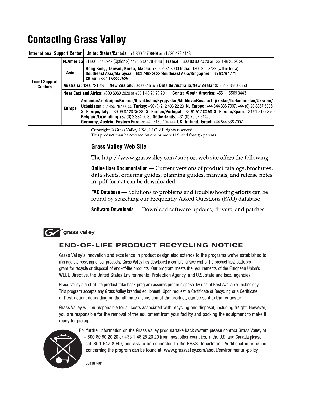
Front view
The front view of the FT server front bezel is shown below. The front bezel comes packaged
separately and should be installed after rack mounting the FT server. It should remain installed
during normal operation for proper cooling of the unit.
A fully loaded system is shown below with the front bezel removed. Front LED indicator states on
the front bezel and on each CPU/IO module and other components visible when the bezel is removed
are described in detail in the Monitoring section of this manual.
8 FT Server Instruction Manual 20131220
Page 9
CPU/IO Module 1
Hard Drive Bays 0-7
Hard Drive Bays 0-7
Optical Disk Drive
On/Off switch
CPU/IO Module 1
LED Module
Related Topics
CPU/IO module 0
power supply
CPU/IO module 1
power supply
Management
LAN for CPU/IO 1
Management
LAN for CPU/IO 0
Teamed
Duplex LANs
3 USB ports
VGA connector
CPU/IO
module 0
CPU/IO
module 1
Backplane
AC cord
stopper
bars
Front status LEDs (bezel removed) on page 59
About the FT Server
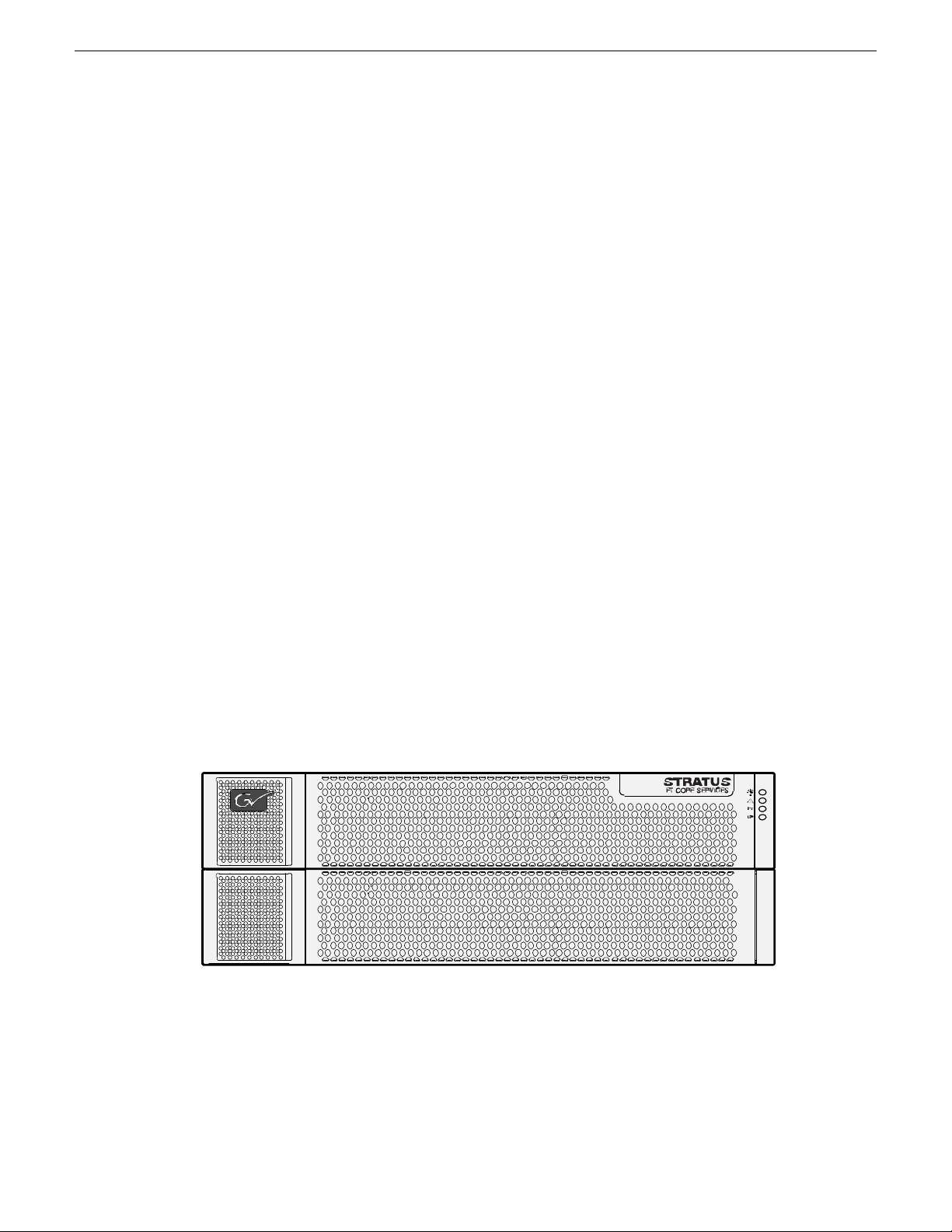
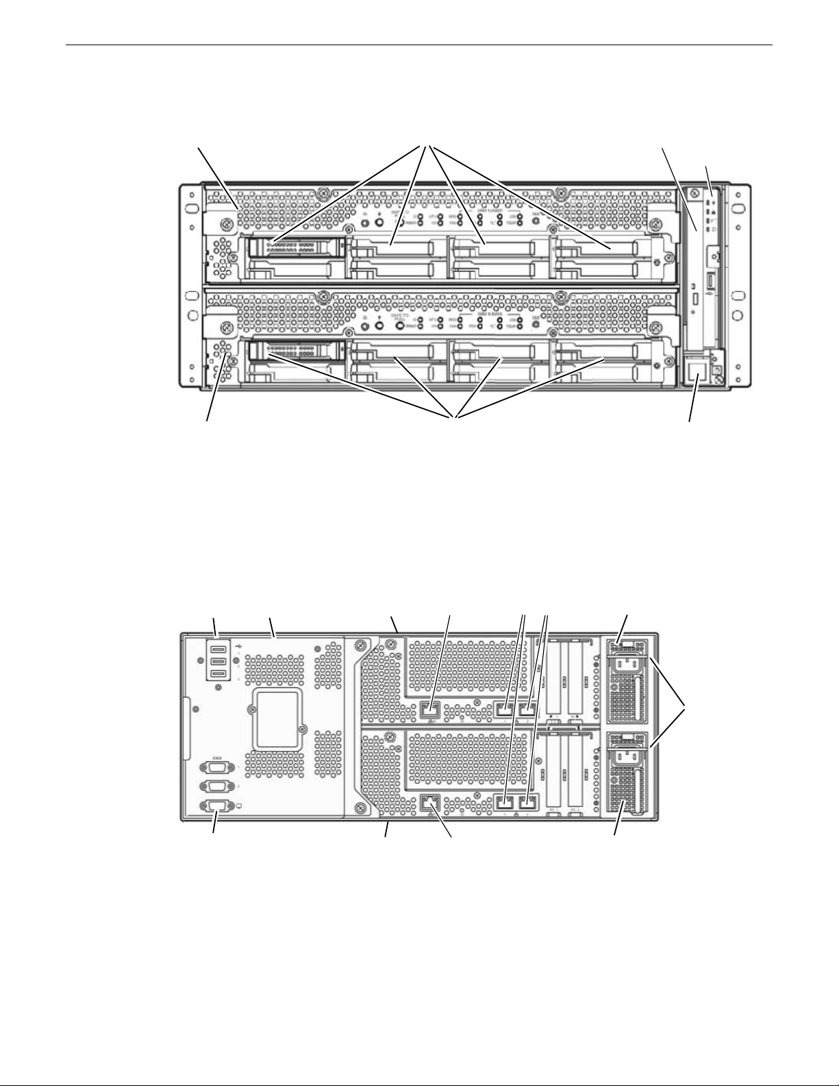
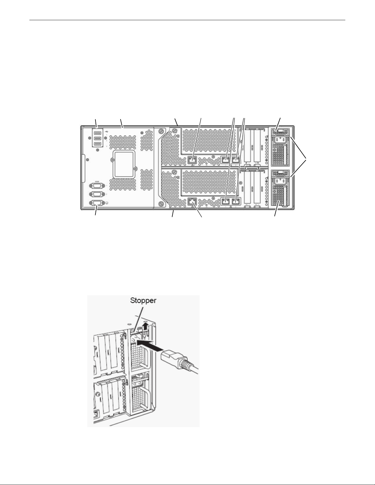
Rear view components
A rear view of the main components of the FT server is shown below.
The system backplane connects to the left rear of both CPU/IO modules. It provides USB connectors
for mouse and keyboard control and serial connectors for maintenance when working with Customer
Service and a VGA connector for connecting to a monitor.
The CPU/IO modules each have a separate removable power supply. When an AC cord in installed
in the receptacles for each power supply, the AC cord stopper bars will be pushed up. In this position,
the CPU/IO modules cannot be removed until the AC cords are removed (no power to CPU/IO
modules).
20131220 FT Server Instruction Manual 9
Page 10

About the FT Server
Each CPU/IO module has a Maintenance LAN connector and dual LAN connectors for
communication. Three USB ports are available on the system backplane for mouse and keyboard
connection. All system cabling is described later in this manual.
Related Topics
Cable connections on page 26
10 FT Server Instruction Manual 20131220
Page 11
FT Server Installation Information
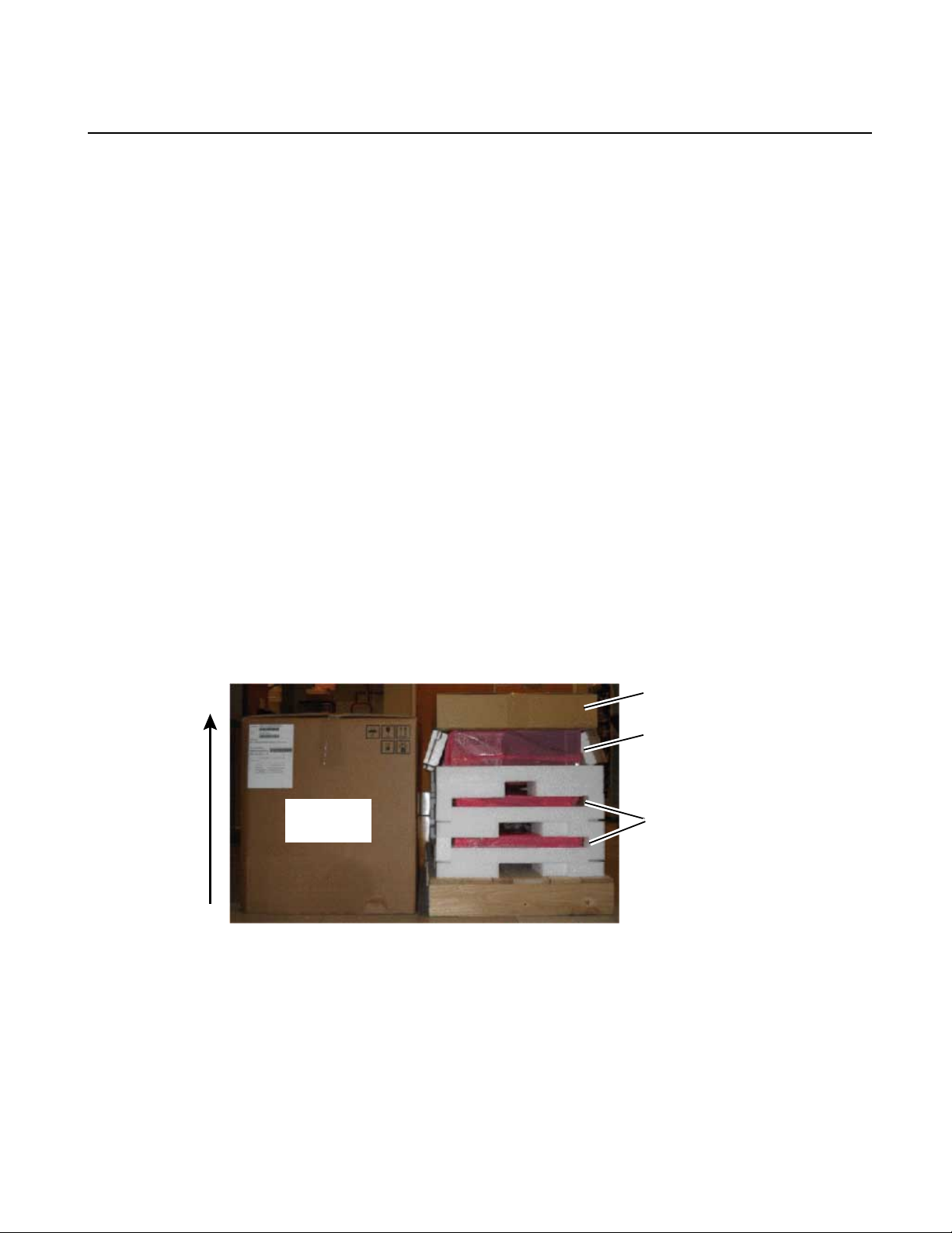
Accessory box
4RU enclosure
2 CPU/IO modules
Lift outer box
off vertically
Installation overview
The FT server must be rack-mounted. It is a precision device and should be installed only by qualied
maintenance personnel.
Observe the following warning and cautions to unpack, install, and use the FT server safely:
• Read and follow the safety section at the beginning of this manual. Failure to do so can pose a
risk of a serious injury, such as a burn, personal injury or damage to physical assets.
• A fully loaded FT server chassis is heavy; have at least two people available for installation.
• This unit may be installed in a standard 19 inch tapped or untapped video rack or a standard 19
inch EIA IT rack.
• Install the product in places designated by the specications only.
• Do not attempt to assemble or disassemble parts of this device alone.
• Use caution to avoid injury to hands and ngers when installing.
Unpacking
The FT server ships packaged as shown below.
You will need two or three people to unpack and rack the FT server safely.
To unpack the shipping box:
1. Cut the plastic bindings holding the outer box to the pallet and lift the outer box vertically to
access the contents.
20131220 FT Server Instruction Manual 11
Page 12

FT Server Installation Information
2. Lift off the accessory box and check for the contents listed below:
• Assorted hardware for installing enclosure and side brackets
• CD with OS software
• Front bezel
• Rack mount side brackets
3. Remove the 4RU enclosure with backplane and optical drive installed.
4. Remove the two identical CPU I/O modules.
5. Install the brackets and 4RU enclosure, then the CPU/IO modules and front bezel as described
in the installation instructions for these items.
Related Topics
Install chassis in rack on page 19
Install CPU/IO modules on page 23
Install or remove front bezel on page 34
Rack types
The FT server can be installed in any of the standard 19 inch video or EIA racks listed below.
• A standard 19 inch video rack with 0.281 round untapped holes with universal spacing requires
the installation of a front adapter ange and a front plate included in the accessory kit.
• A standard 19 inch video rack with #10-32UNF tapped holes requires the installation of a front
adapter ange and a rear adapter ange included in the accessory kit.
• A standard EIA IT rack with square holes uses threaded core nuts to attach the screws hold to
the unit in place. No adapters are required.
Procedures for all three types of rack mounting are described in this manual. Use the procedure that
matches your rack type.
Installing rack rail brackets in untapped rack
The FT server chassis requires 4RUs of space. Be sure to have another person help you to install
the chassis, do not attempt to install it alone.
You will need the following hardware from the accessory kit to install the rack rail brackets to
support the chassis in a untapped rack:
• 2 rack rail mounting brackets
• 2 front ange adapters (ADAPTER-FR)
• 2 plate adapters (PLATE)
• 8 panhead screws
• 4 washers
1. Locate the desired positioning of the FT server in the rack.
12 FT Server Instruction Manual 20131220
Page 13
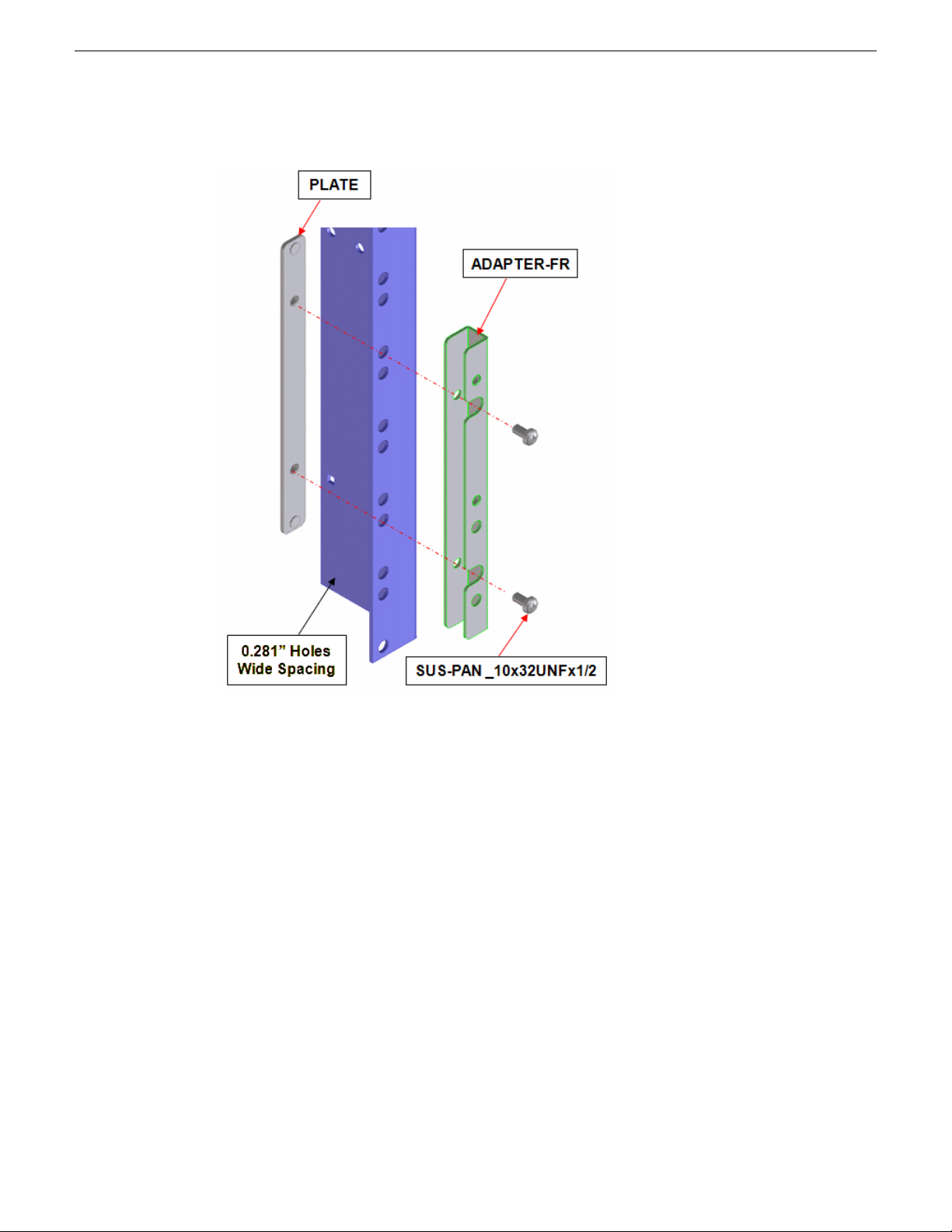
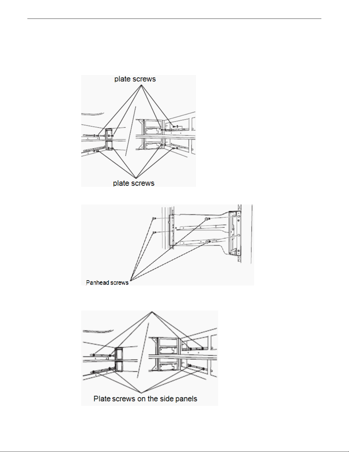
FT Server Installation Information
2. On both sides of the rack, line up the front adapter and plate as shown below.
3. Attach the front adapters and plates to the front of the rack with the panhead screws provided on
the left and right sides of the rack front.
20131220 FT Server Instruction Manual 13
Page 14
FT Server Installation Information
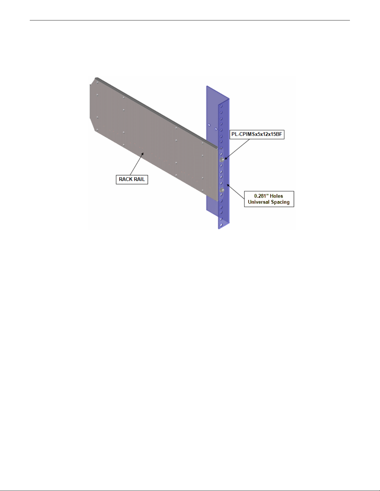
4. Now attach the rear of each rack rail bracket to the left and right rear sides of the rack using the
4 remaining panhead screws and washers. No adapters are necessary for this step.
5. Now go to the instructions for installing the FT server chassis.
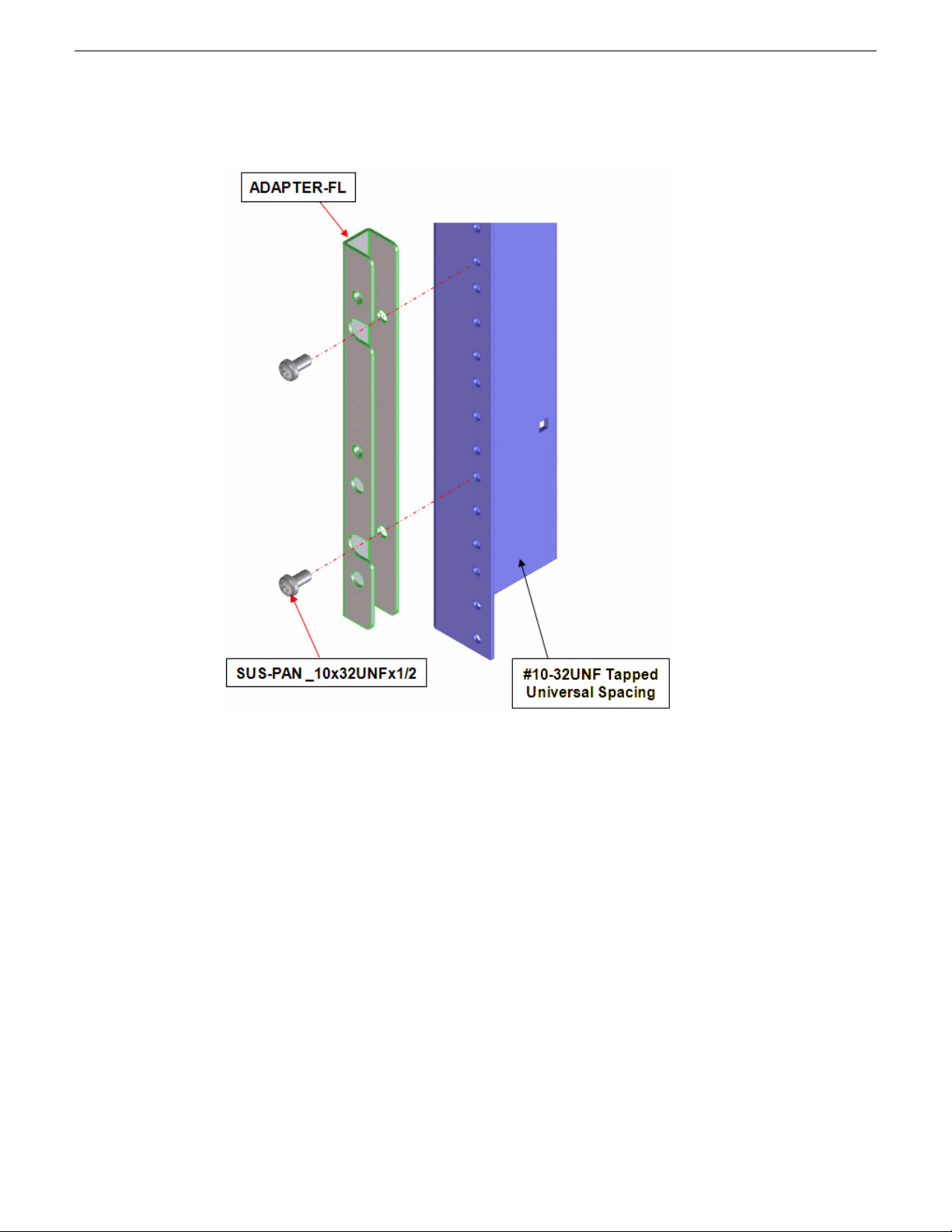
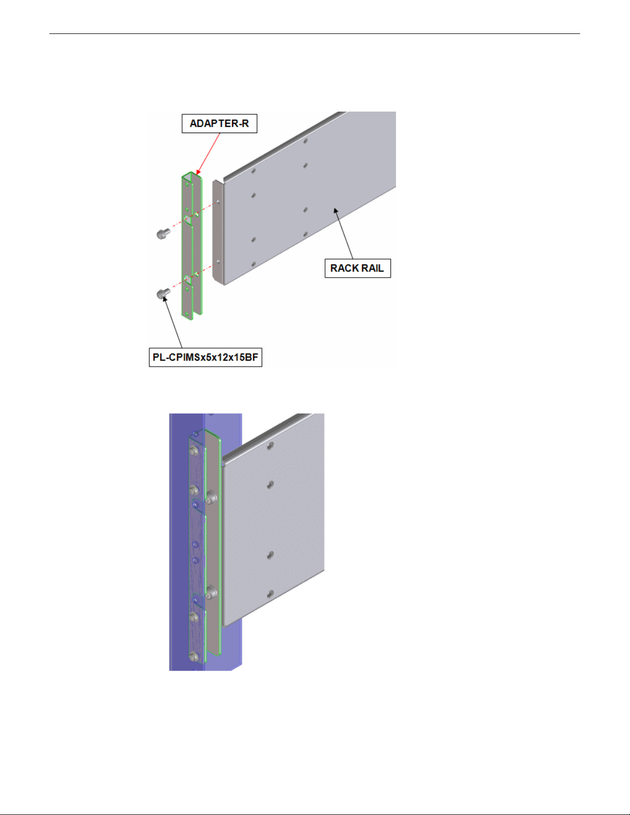
Installing rack rail brackets in tapped rack
The FT server chassis requires 4RUs of space. Be sure to have another person help you to install
the chassis, do not attempt to install it alone.
You will need the following hardware from the accessory kit to install the rack rail brackets to
support the chassis in a tapped rack:
• 2 rack rail mounting brackets
• 2 front ange adapters (ADAPTER-FL)
• 2 rear ange adapters (ADAPTER-R)
• 8 panhead screws
• 4 panhead washers
1. Locate the desired positioning of the FT server in the rack.
14 FT Server Instruction Manual 20131220
Page 15
FT Server Installation Information
2. On both sides of the rack front, line up the front adapter as shown below.
3. Attach the front adapters to the front of the rack with the panhead screws provided on the left
and right sides of the rack front.
20131220 FT Server Instruction Manual 15
Page 16
FT Server Installation Information
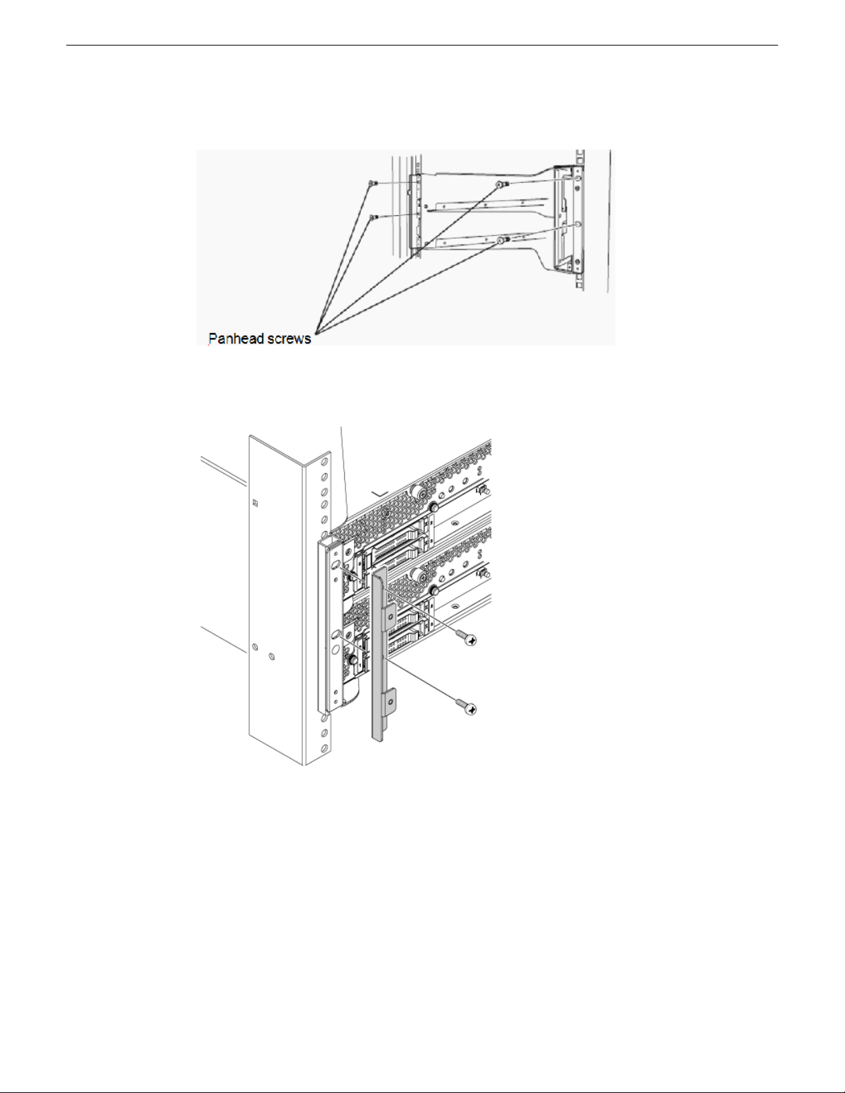
4. Attach a rear adapter to the rear of each rack rail.
5. Attach the rear of each adapter/rack rail assembly to the left and right rear sides of the rack using
the 4 screws and washers.
6. Now go to the instructions for installing the FT serverchassis.
16 FT Server Instruction Manual 20131220
Page 17
Install rack rail brackets in IT rack
The FT server chassis requires 4RU of space. Be sure to have another person help you to install the
chassis, do not attempt to install it alone.
You will need the following hardware from the accessory kit to install the rack rail brackets to
support the chassis in an EIA IT rack:
• 2 rack rail mounting brackets
• 4 washers for panhead screws
• 8 plate screws
• 8 panhead screws
• 4 core nuts (not provided)
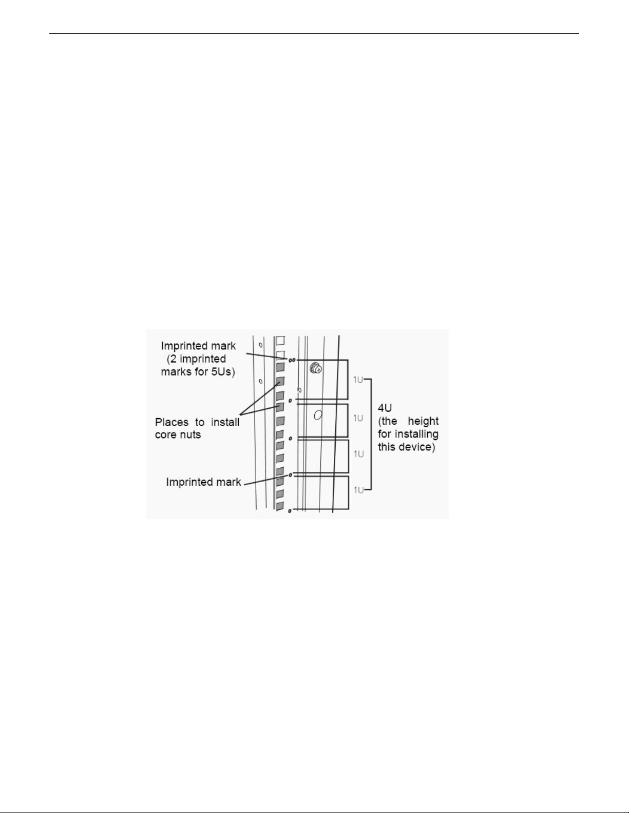
1. Determine where in the rack you want to install the FT server chassis. If using an empty rack,
install it in a lower position near the bottom of the rack rather than at the top to maintain balance.
2. Next to a square hole on the rack, an imprinted mark indicates 1RU. This device is 4RU (about
176 mm), so install it between the imprinted marks that indicate the height of 4RU.
FT Server Installation Information
3. If the rack has front and rear doors, read the instruction that comes with the rack, and open them.
20131220 FT Server Instruction Manual 17
Page 18

FT Server Installation Information
4. Install the rack rail brackets from the rear side of the rack with their at sides facing in. Attach
the brackets to the rack by installing the four panhead screws with washers just above the 1RU
mark and just below the 3RU mark as shown below. Fasten the screws just enough to hold the
brackets in place. Do not tighten them all the way.
5. Install the four core nuts (not provided) to the front of the rack so the left and right sides are in
the same locations as shown below.
18 FT Server Instruction Manual 20131220
Page 19
FT Server Installation Information
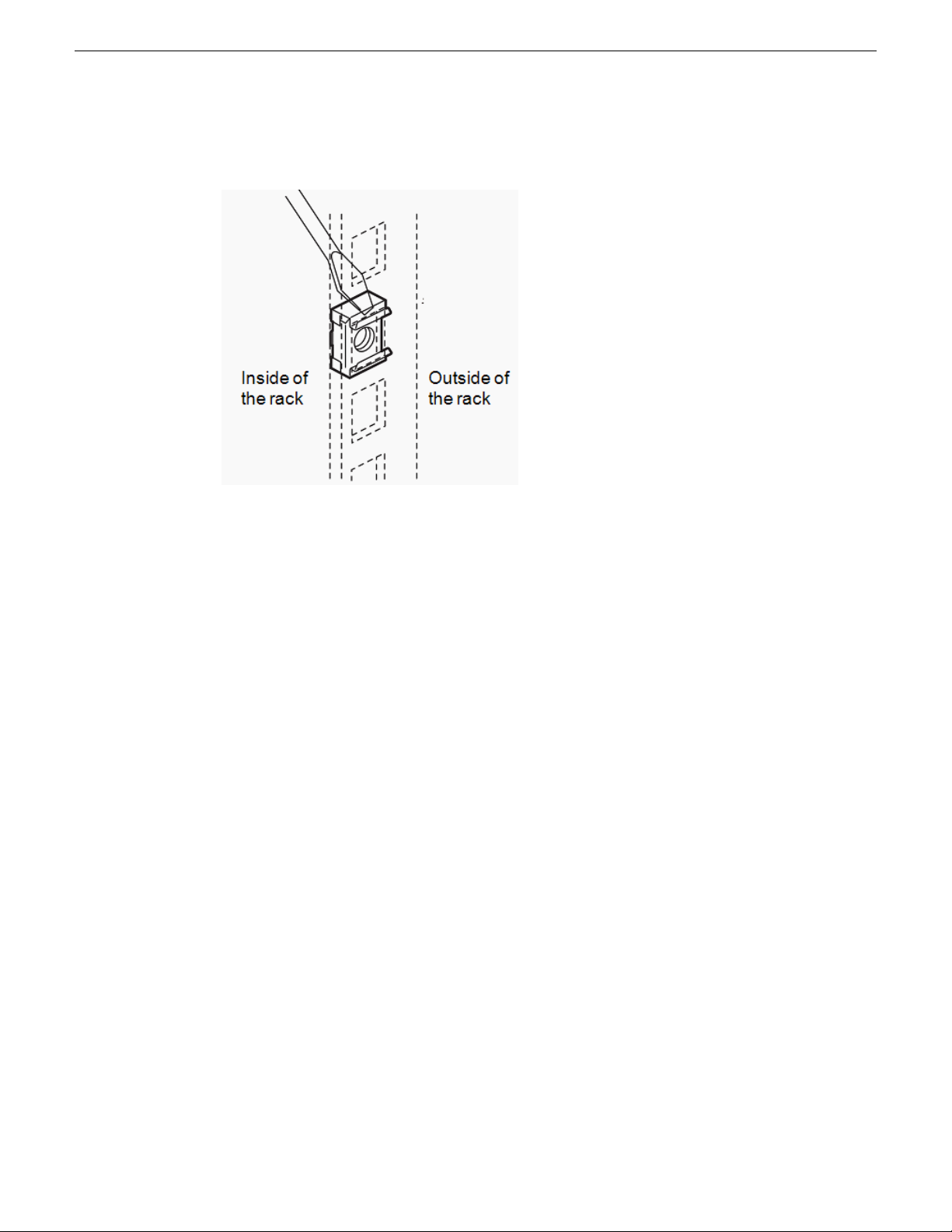
6. Install a core nut from inside of the rack. Hook either of the clips of the core nut to a square hole
of the rack. then hook the other clip to a hole by a at-blade screwdriver.
7. Now go to the procedure for installing the FT server chassis.
Temperature requirements for rack installation
The FT server requires good ventilation and proper airow to operate properly. Make sure you meet
the temperature airow and humidity requirements listed below before installing the FT server in
the rack.
• The operating temperature of the FT server is from 10 degrees C (50 degrees F) to 35 degrees
C (95 degrees F). Please take adequate precautions and measures for maintaining the proper
airow inside the rack as well as in the room so that the internal temperature can be kept within
this range during operation.
• The recommended operating room temperature range is between 15 degrees C (59 degrees F)
and 25 degrees C (77 degrees F).
• Optimum humidity for proper operation should be kept between 20 and 80%.
• Use only the rack installation instructions given in this manual to install the unit and other
components as recommended to avoid overheating conditions.
Install chassis in rack
Once you have installed the rack mounting brackets, install the FT server empty chassis enclosure
in the rack.
20131220 FT Server Instruction Manual 19
Page 20
FT Server Installation Information
NOTE: Installation will vary slightly according to whether there is an adapter on the front of
the rack. A standard EIA IT rack with no adapters is shown.
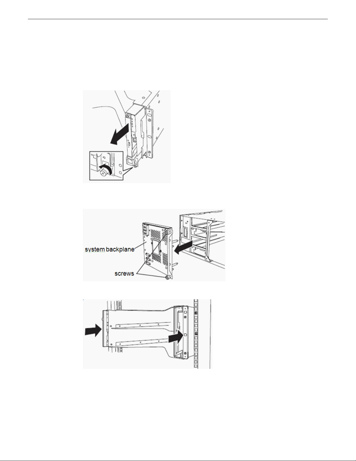
1. Remove the front unit containing the DVD drive and the LED module from the front of the
chassis by loosening the screw at the bottom of the unit and pulling it out.
2. At the rear of the chassis, remove the system backplane. Loosen the two thumb screws then move
the backplane slightly to the right and pull it straight out from the chassis.
3. Insert the empty chassis into the rack from the front.
4. Align the empty chassis so it is centered on the side rack mount rails.
20 FT Server Instruction Manual 20131220
Page 21
FT Server Installation Information
5. Loosely install the 8 plate screws through the holes on the inside of the empty chassis, fastening
to the threaded holes in the side rack mount rails, as shown below. Tighten just enough to hold
them in place.
6. Securely attach the front of the chassis to the rack front with 4 panhead screws.
7. Tighten the 8 internal plate screws you installed earlier to secure the chassis to the side rack
mount rails.
20131220 FT Server Instruction Manual 21
Page 22
FT Server Installation Information
8. Remove the 4 panhead screws you installed earlier.
9. Fasten the bezel brackets to the front of the chassis on each side. Use the 4 panhead screws.
Tighten securely.
22 FT Server Instruction Manual 20131220
Page 23

FT Server Installation Information
10. Reinstall the system backplane in the rear of the chassis by inserting it straight into the slot then
sliding it all the way to the left. Fasten the thumb screws securely by turning to the right.
11. Reinstall the front unit containing the DVD drive and LED module in the front of the chassis in
the reverse order done in Step 1 of this procedure.
12. Now install the two CPU/IO modules as described in the next section.
Install CPU/IO modules
This procedure explains how to install the CPU/IO modules into the chassis enclosure once it is
installed in the rack. It is recommended to have two people available to do this procedure.
There are two CPU/IO modules in the system, Module 0 (in the top slot) and Module 1 (in the bottom
slot). When you receive these modules from the factory they are identical (mirrored). Either module
from the factory may be installed in the top or bottom slot. Both modules have their power supply
and all hard drives installed.
NOTE: Upon power up, the top module will be automatically designated as the Primary and the
module in the bottom slot will be designated as the Secondary. All hard drives installed have been
20131220 FT Server Instruction Manual 23
Page 24
FT Server Installation Information
mirrored at the factory. Once you have powered up the system, Primary and Secondary modules
or any hard drives should not be swapped.
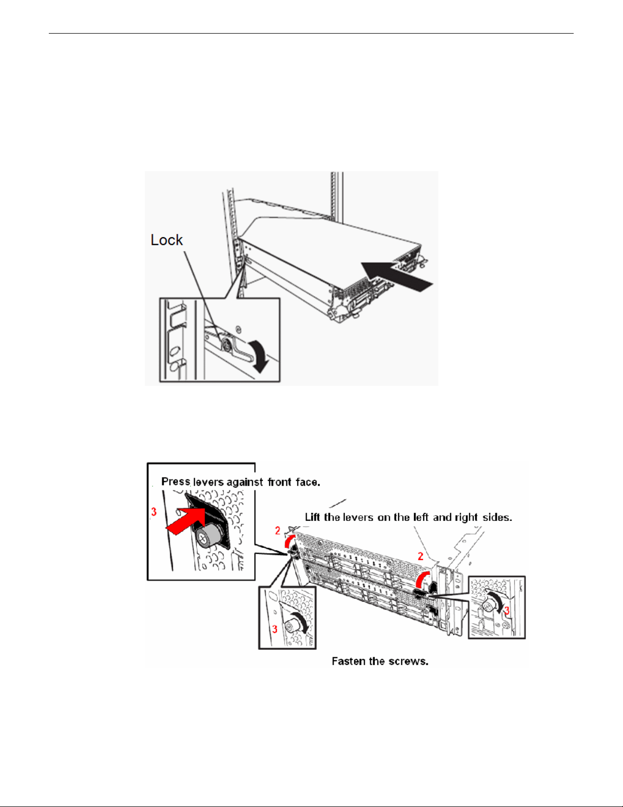
1. Mount either module into the enclosure by sliding it into the top slot. As you slide the module
in, press down on the side locking lever on the left side of the module so the module slides in
past the locking mechanism. You will hear a click when the side locking lever engages.
2. Once the module is all the way in, lift the front locking levers into position on both sides of the
module up as shown below.
3. Press the side levers rmly against the front face as you turn the screws to the right to secure the
module in the frame.
24 FT Server Instruction Manual 20131220
Page 25
4. Repeat this procedure to install the bottom module.
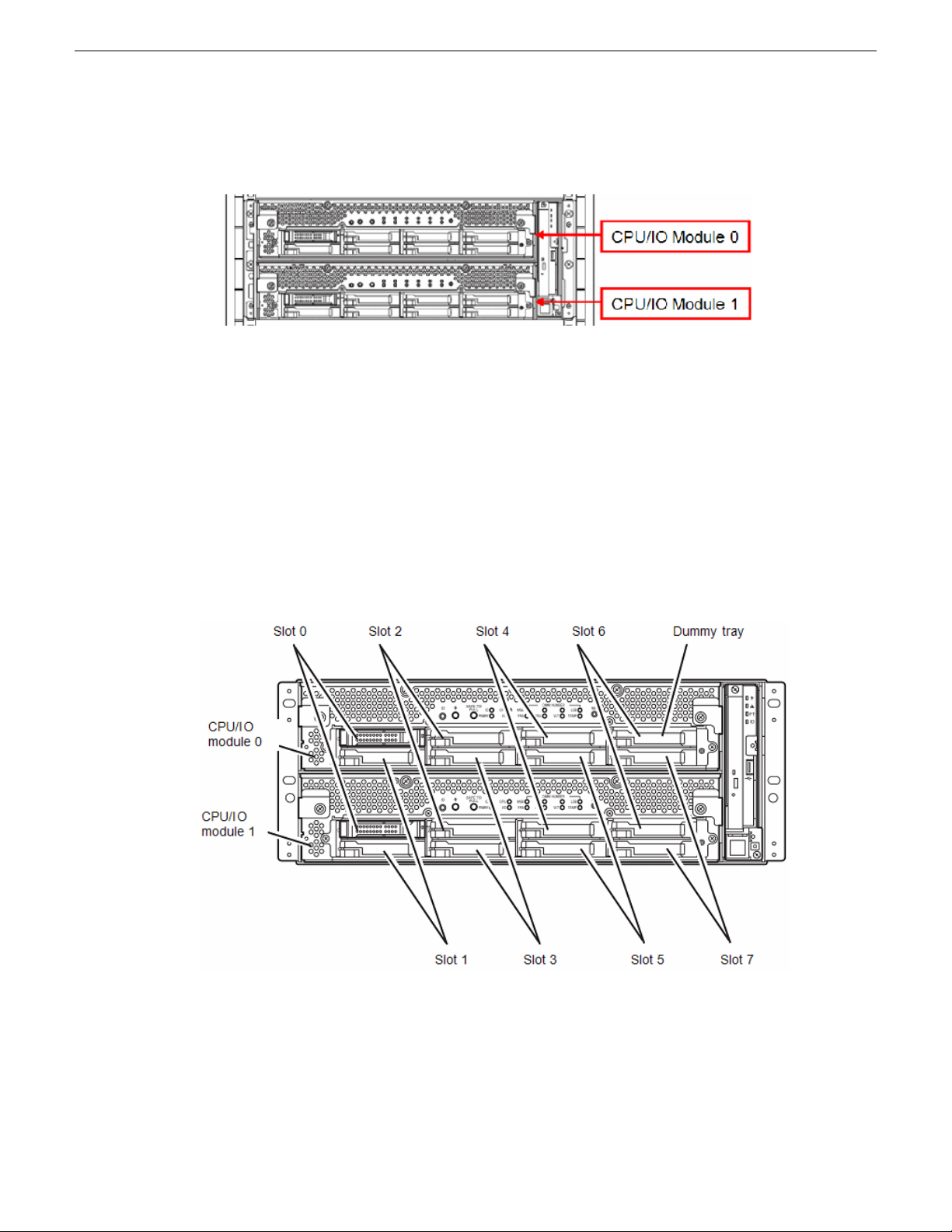
The resulting installation should look like the example below from the front.
5. Install the front bezel as described in the topic describing this procedure.
2.5 inch hard disk drives
The 2.5-inch hard disk drive bays in front of the FT server can mount up to 16 hard disk drives with
the 2.5 inch width exclusive trays. All hard disk drives are installed and mirrored at the factory. Do
not swap the positions of any hard disk drives.
The operation is executed on the created mirror volume with installed hard disk drive pairs such as
slot 0 on CPU/IO module 0/1, slot 1 on CPU/IO module 0/1, slot 2 on CPU/IO module 0/1. (The
OS is installed on the mirror volumes that consist of the hard disks in the slot 0.)
FT Server Installation Information
Hard disk drive slot locations are shown below.
Empty slots in the 2.5-inch hard disk drive bay contain dummy trays. The dummy trays are inserted
to improve the cooling effect within the device. Always insert the dummy trays in the slots with no
hard disk drives installed.
20131220 FT Server Instruction Manual 25
Page 26
CPU/IO module 0
power supply
CPU/IO module 1
power supply
Management
LAN for CPU/IO 1
Management
LAN for CPU/IO 0
Teamed
Duplex LANs
3 USB ports
VGA connector
CPU/IO
module 0
CPU/IO
module 1
Backplane
AC cord
stopper
bars
FT Server Installation Information
Cable connections
Cable connections to the FT server are made on the rear of the unit to the backplane and to both
CPU/IO modules as described here.
Refer to the illustration of the rear module and its cable connections below.
1. Connect a mouse and keyboard to the USB connections on the backplane.
2. Connect a at screen to the bottom VGA serial connector.
3. Connect the AC cords to each of the CPU/IO AC receptacles but do not power up.
Notice that when the AC cord is inserted, the AC Stopper bars will engage as shown below. The
Stopper bars prevent you from removing a CPU/IO module with the AC cord connected (while
powered up).
26 FT Server Instruction Manual 20131220
4. The Teamed Duplex LANs connect the FT server to the network as appropriate for the FT server's
use as a Grass Valley system device.
Page 27
STRATUS-CS-FT server: Core (B1, C1)
These cabling instructions apply to GV STRATUS Express server and GV STRATUS Core server,
specied as follows:
• Grass Valley FT server with one or more roles from the following list only:
• GV STRATUS Ingest Services (Required)
• GV STRATUS Control Panel Service (Required)
• GV STRATUS Common Services (Required)
• License Manager (Required)
• GV STRATUS Data Mover Engine (Required)
• GV STRATUS Proxy Express Server (Required on Express server)
• GV STRATUS Control Panel (Required)
• GV STRATUS Core Services (Required)
• GV STRATUS Summit MDI (Required)
• GV STRATUS Diva MDI (Optional)
• GV STRATUS Event Viewer
• GV STRATUS FlashNet MDI (Optional)
• GV STRATUS Generic FTP MDI (Optional)
• GV STRATUS Proxy Encoder (Optional)
• GV STRATUS Workow Engine (Optional)
• GV STRATUS Rules Engine (Optional)
• GV STRATUS Xcode Control Engine (Required only on systems with GV STRATUS Rules
Engine)
• GV STRATUS Trafc Gateway (Optional)
• Aurora Playout Server Components (Optional)
• GV STRATUS Application (Use for test purposes only)
FT Server Installation Information
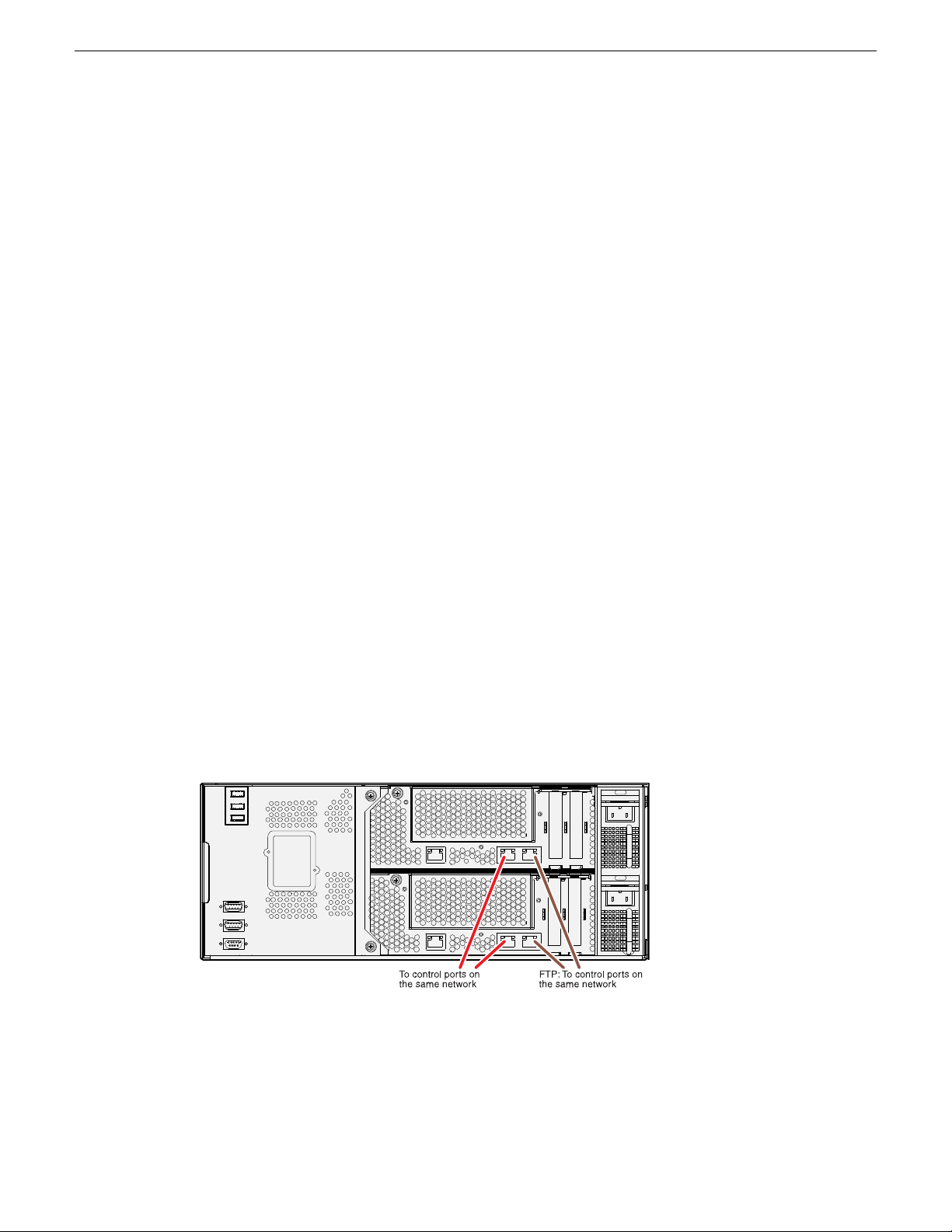
These roles require a connection to the control network and the FTP/streaming network.
NOTE: Network ports on CPU/IO module 1 and on CPU/IO 2 both connect to the same network.
For example, both control ports connect to the same control network. Do not attempt to connect
to different networks.
20131220 FT Server Instruction Manual 27
Page 28
FT Server Installation Information
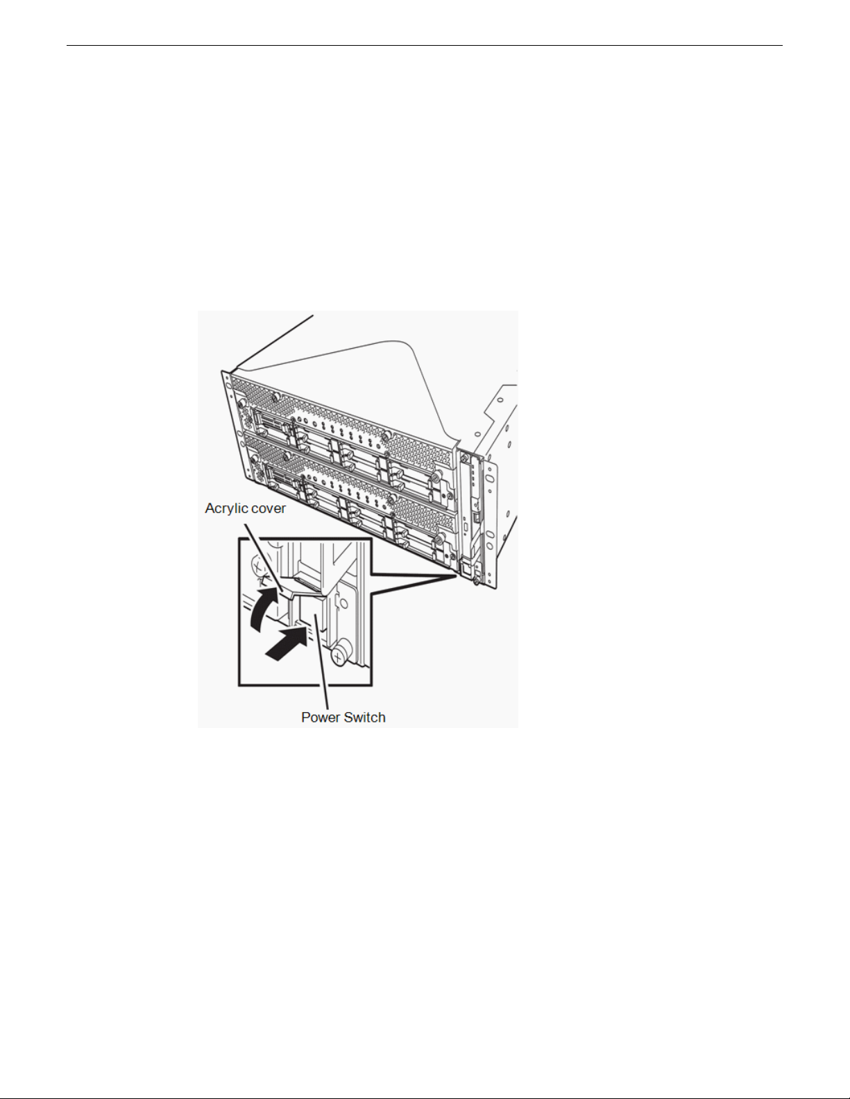
Power up
Power on the display unit and other peripheral devices connected to the server rst.
NOTE: If the power code is connected to a power controller like a UPS, ensure that it is powered
on.
Follow the steps below to turn on the FT server power.
1. With the front bezel removed, press the power switch located on the front panel. Lift up the
acrylic cover in front of the power switch, and press the power switch to turn on the FT server.
28 FT Server Instruction Manual 20131220
Page 29

FT Server Installation Information
2. Once the system has booted up, the GV logo should be displayed on the screen of the display
unit. While the GV logo is displayed on the screen, the FT server is performing a power-on self
test (POST) to check the unit. Upon the completion of POST, the OS will start.
If the server nds errors during POST (power up self test), it will interrupt POST and display an
error message.
CPU/IO module status
The CPU/IO module (0 or 1) that is started rst is managed as the primary, and the module started
later is managed as the secondary. If one CPU/IO module is disconnected because of a failure, the
other module becomes the primary.
The CPU/IO module to be started rst is selected depending on the primary/secondary status of
modules when the server was shut down the last time.
The following devices are connected to the primary CPU/IO module by the connectors on the system
backplane and access both CPU/IO modules 0 and 1. When one CPU/IO module is disconnected
because of a failure, those are switched to the other module automatically and continue operating.
• VGA (display)
• USB device (keyboard, mouse, optical disk drive)
NOTE: Both CPU/IO modules 0 and 1 can access the optical disk drive. If one CPU/IO module
is isolated because of a failure, only the active (Primary) CPU/IO module can access the drive.
NOTE: The drive letter of the optical disk drive is reallocated automatically. The unused letter
is allocated to the drive in the order of D to Z. If you want to set the xed drive letter to the optical
disk drive, specify the letter which is not allocated in the order of D to Z after setting the hard
disk drive letter.
20131220 FT Server Instruction Manual 29
Page 30

FT Server Installation Information
POST check
POST (Power-On Self Test) is a self-test function stored on the motherboard of the FT server.
When you power on the server, the POST will start automatically to check the motherboard, ECC
memory modules, CPU/IO modules, keyboard, mouse, etc. It also shows startup messages for various
BIOS setup utilities.
To view details of the POST, do one of the following:
• While the POST is being performed, press the Esc key.
• View the POST details from the beginning without pressing the ESC key when the BIOS menu
appears. To do this, select System Configuration, then Advanced and set the Boot-time Diagnostic
Screen to Enabled.
• View the test items and details from a management PC where ESMPRO Manager is installed.
You do not always need to check the POST details. You will need to check messages when one of
the following conditions exist:
• Installation of a new FT server.
• A failure is suspected.
• Several beeps occur between the time of the power-on and OS start-up.
• The display unit shows an error message.
POST flow details
This topic walks you through how POST is performed.
1. When you power on the system, one selected CPU/IO module will start up.
POST will be performed on this selected CPU/IO module.
2. The memory check starts.
A message appears at the upper left of the screen to show that the basic and expanded memories
are being counted. The memory check may take a few minutes to complete depending on the
server's memory size. Likewise, it may take about one minute for the screen to appear when the
server is rebooted.
3. The server starts the processor check, IO check, and initialization.
Several messages appear showing the ID of the selected CPU/IO modules, information on the
processor, detection of the keyboard and mouse, etc
30 FT Server Instruction Manual 20131220
Page 31

FT Server Installation Information
4. A message appears at the lower left of the screen (shown below), prompting for startup of the
BIOS setup utility SETUP.
You will need to start it when you want to modify the conguration for using the server. Unless
this message appears together with an error message, you do not need to start the utility to modify
the conguration. (If you wait for a few seconds, POST will go on automatically.)
To start the SETUP utility, press F2 while the above message is displayed.
When SETUP is completed, the server will reboot itself automatically and perform POST.
5. A message appears prompting for startup of the SAS BIOS setup utility.
When a built-in SAS controller is detected, a message will appear prompting for startup of the
SAS BIOS setup utility. (If you wait for a few seconds, POST will go on automatically.)
If you press Ctrl + A, the SAS BIOS setup utility will start. However, you usually do not need
to use the setup utility. For setting and parameter functions, see the Conguration section of this
manual.
When SETUP is complete, the server will reboot automatically and perform POST from the start
again.
6. The screen shows the ID numbers of the connected disk drive.
7. Upon completion of POST, the password entry screen appears prior to OS startup.
The password entry screen will appear after the normal termination of POST only if you have
set a password in the BIOS setup utility SETUP.
You can enter a password up to three times. If you enter an incorrect password three times, the
startup will be unsuccessful. In this case, turn off the power and then turn it on again after waiting
30 seconds to boot the server.
IMPORTANT: Set a password after the OS installation.
8. Upon completion of POST, the OS will start up.
POST error messages
When the server detects an error during POST, it will notify you of the occurrence in the following
manners:
• Displays an error message on the display unit.
Write down the error messages. They will serve as helpful information during maintenance or if
you need to contact Customer Service.
POST Message
In a normal situation, the POST Code and BIOS Build Number are displayed on the top side of the
Virtual LCD.
20131220 FT Server Instruction Manual 31
Page 32

FT Server Installation Information
The POST running LCD format is shown in the table below.
1
The POST running LCD format detail is shown in the table below.
The message displays the state of duplication on the upper row of LCD by software driver after the
OS boots.
The Boot message for the Virtual LCD is shown in the table below.
FEDCBA9876543210
ZZZZSOIBXXXX0
DescriptionDisplay
Normal: Currently executing POST codeXXXX
BIOS Build NumberZZZZ
ActionCommentsRepresentationRowLCD Message
DC ONUpperCPU broken
If CPU part is
broken, LCD is
displayed on the
broken CPU/IO
modules.
The module
displayed LCD
is broken.
Change the
broken CPU/IO
module.
DC ONUpperI/O broken
If IO part is
broken, LCD is
displayed on the
broken CPU/IO
modules.
The module
displayed LCD
is broken.
Change the
broken CPU/IO
module or PCI
card.
DC ONUpperSystem Duplex
When the
system is under
System duplex
completed.
duplex mode,
the message is
displayed on
both CPU/IO
modules.
DC ONUpperSystem Simplex
When system is
not under
duplex mode,
The system is
working under
simplex mode.
the message is
displayed on the
CPU/IO module
working
normally.
32 FT Server Instruction Manual 20131220
Page 33

System Power LED
System Fault LED
System FT LED
ID LED
FT Server Installation Information
ActionCommentsRepresentationRowLCD Message
POST or OS Error behavior
If the POST or OS startup does not nish normally, the server will reboot itself automatically.
At the time of reboot, it will select the other CPU/IO module and run POST or OS startup.
In this manner, the server retries POST or OS startup with different combinations of CPU/IO modules.
If POST does not nish normally with any combinations, the server will stop with the state of DC
OFF or POST end with an error message displayed.
While performing retries, the server displays or registers the error types.
Front panel LEDs
On the right side of the front of the unit are four LEDs that show the current system conditions.
DC ONUpperSplit Mode
Active UpgradeThe message is
displayed on the
standby CPU/IO
module during
Split mode.
20131220 FT Server Instruction Manual 33
The LED meanings are shown in the table below.
System Power
LED
Indicates Power condition of
system.
DescriptionFunctionLED Name
Green: System DC ON.
OFF: System DC OFF or AC OFF.
Page 34

FT Server Installation Information
DescriptionFunctionLED Name
System Fault
LED
LED
ID LED
LED Amber is on or blinking if
either CPU/IO module is broken.
When LED is on, detail
information is displayed on
ExpressScope (LED panel that
is visible when front bezel is
removed).
Indicates system is duplexing.System FT
Pushing ID Switch, or
demanding ID from remote.
Amber: Either CPU/IO module has a failure.
A CPU/IO module can not be brought up in case
that CPU/IO module is not connected to AC.
Amber blinking:
It is difcult to distinguish a faulty CPU/IO
module. For example, indicating a loss of
synchronization. In this case, it is possible that
both CPU/IO modules will need to be replaced.
When analyzing Ringbuffer, there is a possibility
that the cause and faulty CPU/IO module can be
found out.
Green: Duplexing
Green blinking: Split operating by Active
Upgrade.
Off: Running under simplex.
Off: LAN or FC function is not duplexing.
Blue: ID switch has been pressed.
Blue blinking: Demanded ID from remote.
Install or remove front bezel
When your system is up and operating normally, install the front bezel. Mount it on the front of the
unit and turn the thumb screws on both sides to the right.
You may remove the front bezel while the unit is powered up to check LED status.
Off: No demand.
34 FT Server Instruction Manual 20131220
Page 35

FT Server Installation Information
To remove the front bezel:
1. Unscrew the two thumb screws on either side of the front bezel.
2. Remove the front bezel carefully and set in a protected location to prevent damage.
NOTE: Keep the front bezel installed on the unit during normal operation.
Power off
Follow the steps below to turn off the power. If the FT server is plugged to a UPS (Uninterrupted
Power Supply), refer to the manuals included with the UPS or the application that controls the UPS.
1. Perform a normal shutdown from the OS.
The entire system will be powered off automatically. (Note: the POWER switch on the primary
side will remain lit when AC power is supplied.)
2. Power off all peripheral devices.
20131220 FT Server Instruction Manual 35
Page 36

FT Server Installation Information
36 FT Server Instruction Manual 20131220
Page 37

Configuring the FT Server
Configuration overview
If you have received your FT server from the factory for use in a STRATUS Media Workow
system, it has been congured with all necessary STRATUS software and all server functionality
such as duplexed LANs and Rapid Disk Resync (RDR) has been performed at the factory. Once
you have installed and powered up your system, refer to the STRATUS documentation for further
instructions.
If you have received your FT server from the factory as a replacement for an older server in a
STRATUS Media Workow system, it will require the installation of STRATUS software using
SiteCong. The Discovery Agent utility necessary for SiteCong has been installed at the factory
and all server functionality such as duplexed LANs and Rapid Disk Resync (RDR) has been
performed. Once you have installed and powered up your system, refer to the STRATUS Media
Workow documentation for further instructions.
Service Program configuration
The FT server achieves the duplex system using the following service programs which are congured
at the factory, in addition to dedicated drivers.
Service program names shown in Services:
• ftSys eService (outputs SEL (System Event Log)
• ftSys Maintenance and Diagnostics (MAD) (provides ft control management and diagnostic
features)
• ftSys RPC Provider (manages WMI conguration and status)
• Windows Management Instrumentation
• ftSys SSN (contols communication between modules, such as when executing an Active Upgrade)
• SNMP Service
• Alert Manager Main Service
• ESMFSService
• ESMCommonService
• ESRAS Utility Service
• ESMPS
• Virtual Disk Service (vds)
• DHCP Client
The above programs are necessary for the FT server operation. Do not stop these services.
20131220 FT Server Instruction Manual 37
Page 38

Conguring the FT Server
When minimizing the number of operating service programs temporarily is required, the following
service programs may be stopped:
• ESRAS Utility Service
Make sure to restart the operations of stopped service programs immediately after the backup
processes are completed.
Confirming control software version
This topic describes how to check the version of FT server Control Software, which consists of
various types of software for fault tolerance. Perform the procedure when you need to check the FT
server Control Software version of the current system before adding units or connecting to other ft
servers.
Conrm the version following the steps below:
1. Log on the system as an authorized Administrator. Select ftServer Control Software from the list
of programs to check the Product version.
2. Open Control Panel from the Start menu.
3. Open Programs and Features. If the Programs and Features icon is not displayed, open Programs
and click Programs and Features.
4. Select ftServer Control Software from the list of programs to check the Product version.
Disk operations
The topics in this section explain disk operation using the RDR (Rapid Disk Resync) function.
The FT server duplicates disks to secure data by using the Rapid Disk Resync (RDR) function. The
topics in this section describes operations such as conguration of dual settings to disks and
replacement of disks.
Dual disk configuration overview
The FT server secures data by setting the dual disk conguration using the RDR (Rapid Disk Resync)
function in the control software. Dual disk conguration procedures differ depending on whether
you are conguring the system disk (slot 0) or the data disk (slot 1 to slot 7).
There are two different procedures:
• To congure the dual disk of the system disk, refer to the System Disk Dual Conguration
Procedure.
• To congure the dual disk of the data disk, refer to the Data Disk Dual Conguration Procedure.
IMPORTANT: Refer to the following notes:
• The CPU/IO module has a processor function part and an IO function part and monitors and
manages each part. The IO function part is referred to as PCI module in this section.
• Hard disk drives mounted in built-in slots need to be duplexed.
38 FT Server Instruction Manual 20131220
Page 39

Conguring the FT Server
By setting RDR, as the following gure and table show, dual conguration is set between the disks
of the corresponding slots and then these disks are recognized as one virtual disk by Windows (such
as Disk Management and Device Manager).
CAUTIONS: Read the following cautions before using the RDR Utility:
• RDR can only be used on the disks inserted into the built-in slots of the FT server. It cannot be
used on the dynamic disk.
• Be sure to use a basic disk as the system disk. Only a data disk can be used for a dynamic disk.
• Be sure to specify RDR to all disks inserted in the built-in slots and make duplex settings.
• Be sure to congure the RDR settings in the same way not only when the OS is installed but
also when the disk is added to the PCI module.
• RDR can only be used on basic disks. If a span volume or stripe volume is needed, congure
RDR to a basic disk and then change the disk to a dynamic disk using Disk Management.
• Before performing physical formatting, change OS Boot Monitoring to Disabled on Server
Monitoring Configuration in the BIOS setup utility.
20131220 FT Server Instruction Manual 39
Page 40

Conguring the FT Server
• If the system is shut down (or restarted) while the mirror is broken, or a long time (30 minutes
or longer) has passed after the mirror is broken, the mirror resynchronization target will be the
entire area of the partition existing on the disk. For example, if the mirroring has been broken
due to a PCI module failure, when you shut down the system and replace the PCI module in such
a state, the entire area of the partition existing on the disk needs to be resynchronized.
• Create a data disk partition after conguring the RDR. If you create a data disk partition before
conguring the RDR, the partition's drive letters may be deleted when the RDR is congured.
System disk dual configuration procedure
Read the Dual Disk Conguration Overview before performing this procedure.
Congure the dual disk of the system disk with the following procedure.
NOTE: To perform this procedure, you need to log on as an administrator or a member of an
administrator group.
1. Go to Start | All Programs | RDR | RDR Utility and start the RDR utility. On the left pane of the
RDR utility, select Slot 0 of PCI module 10 under SCSI Enclosure and conrm that the ConfigState
on the right pane reports: Boot, Configured, Active, Imported.
TIPS:
• The RDR Utility display does not refresh automatically. From the menu, go to Action and
click Refresh or press the F5 key every time you conduct disk-related operations such as
connecting/disconnecting disks or conguring the RDR.
• On the RDR Utility, PCI module names appear as follows. PCI module (CPU/IO module 0)
− PCI module 10 PCI module (CPU/IO module 1) − PCI module 11.
NOTE: Be sure to use new disks or physically formatted ones with the same capacity as the
synchronization source disk. If you use other disks, dual conguration will not be correct.
2. Insert the disk for the dual conguration into Slot 0 of PCI Module 11.
40 FT Server Instruction Manual 20131220
Page 41

Conguring the FT Server
3. Start Computer Management by going to Start | Administrative Tools and select Disk Management
in the left tree. If the disk reports Not Initialized on the right pane, right-click on the relevant disk
to initialize.
IMPORTANT: A popup window prompting you to reboot appears when inserting or initializing
the disk; however, you do not need to reboot the system. Select Restart Later to exit the popup
window.
4. Right-click on Slot 0 of PCI module 11 from the left pane of the RDR Utility and click Add
Physical Disk To RDR Virtual Disk.
20131220 FT Server Instruction Manual 41
Page 42

Conguring the FT Server
5. Click OK.
42 FT Server Instruction Manual 20131220
Page 43

Conguring the FT Server
6. Verify that disk synchronization has been started and the status of the DISK ACCESS LED and
RDR Utility display changes during synchronization as described in the table and RDR Utility
screen below:
RDR UtilityDisk Access LEDDuring synchronization
disk
Amber and blinkingSynchronization source disk
Status: N/ACondition:
Simplex
Amber and blinkingSynchronization destination
Status: N/ACondition:
Syncing
N/ARDR Virtual disk
Condition:
Simplex
Status: Resync x %
(x=0, 4, 8,...96
IMPORTANT:
• The time required for synchronization varies depending on the partition size on the disk. For
a 40GB partition, it takes about 50 minutes.
• Setting dual disk conguration may not complete if you reboot the system during the
synchronization. Do not reboot the system before the synchronization process completes.
• If the system stops by terminating Windows improperly such as pressing the Power button,
the whole disk area already synchronized will be resynchronized after rebooting the system.
Verify that disk synchronization is complete by noting that the status of the DISK ACCESS LED
and RDR Utility display change as described in the table and RDR Utility screen below:
RDR UtilityDisk Access LEDSynchronization completed
StatusCondition
20131220 FT Server Instruction Manual 43
Page 44

Conguring the FT Server
disk
RDR UtilityDisk Access LEDSynchronization completed
N/ADuplexGreen and blinkingSynchronization source disk
N/ADuplexGreen and blinkingSynchronization destination
NoneDuplexN/ARDR Virtual disk
Data disk dual configuration procedure
NOTE: Read the Dual Disk Conguration Overview before performing this procedure.
Follow the procedure below to congure dual data disks for slots 1 to 7.
IMPORTANT: The following procedure describes how to congure the dual disk for Slot 1. To
congure the dual disks for Slot 2 to Slot 7, follow the same instructions for Slots 2-7 as Slot 1,
selecting the proper disk.
1. Insert a disk for the dual conguration into slot 1 of PCI Module 10. If a disk is already mounted,
this procedure is not necessary. Go to step 2.
44 FT Server Instruction Manual 20131220
Page 45

Conguring the FT Server
2. Start Computer Management by going to Start | Control Panel |, Administrative Tools, and select
Disk Management on the left tree. If the disk which is to be set as dual conguration shows as
Not Initilized on the right pane, right-click on the relevant disk to initialize.
IMPORTANT: A popup window prompting to reboot appears when you insert or initialize the
disk; however, you do not need to reboot the system. Select Restart Later to exit the popup window
3. Go to Start | All Programs | RDR | RDR Utility | and start the RDR Utility. On the left pane of the
RDR Utility, right-click on the Slot 1 disk of PCI Module 10 and choose Create RDR VirtualDisk.
NOTE: Depending on the disk status, it takes time to set RDR, and the RDR Utility may stop
for a few minutes. This is not an error. Allow it to nish.
20131220 FT Server Instruction Manual 45
Page 46

Conguring the FT Server
4. When the dialog box shown below comes up asking you to do a system reboot, click Yes.
5. Click OK when the operation complete dialog box appears.
NOTE: If you set RDR on a disk that includes a system partition disabled to mount, a system
restart pop-up message appears. The system reboots after 2 minutes after clicking Yes. After
rebooting, perform the procedures starting with step 6 below.
6. Insert the disk to perform dual conguration into the Slot 1 of PCI module 11, and perform the
procedure in step 2. If a HDD is already mounted, this procedure is not necessary. Perform the
procedure in step 2 only.
NOTE: Be sure to use new hard drive disks or physically formatted ones with the same capacity
as the synchronization source disk. If you use other disks, dual conguration will not work
properly.
46 FT Server Instruction Manual 20131220
Page 47

Conguring the FT Server
7. Right-click on Slot 1 of the PCI module 11 from the left pane of the RDR Utility, then click Add
Physical Disk To RDR Virtual Disk.
8. Click OK in the dialog box that appears.
20131220 FT Server Instruction Manual 47
Page 48

Conguring the FT Server
9. Verify that disk synchronization has started and the status of the DISK ACCESS LED and RDR
Utility display changes as shown in the table and the RDR Utility screen below.
disk
RDR UtilityDISK ACCESS LEDDuring synchronization
StatusCondition
N/AOnlineGreen and blinkingSynchronization source disk
N/ASyncingAmber and blinkingSynchronization destination
SimplexN/ARDR Virtual disk
Resync X %
(x = 0, 4, 8, ...96)
IMPORTANT:
• The time required for synchronization varies depending on the partition size on the disk. For
a 73GB partition, it takes about 80 minutes. When the partition does not exist on the disk, the
synchronization is completed immediately after the RDR is set, and Op State: State changes
to Duplex. However, when the dynamic disk is used, the time required for synchronization
depends on the disk size regardless of whether or not the partition exists on the disk.
• Setting dual disk conguration may not complete if you reboot the system during the
synchronization. Do not reboot the system before the synchronization process completes.
• If the system stops by improper termination of Windows such as pressing the Power button,
the entire synchronized disk area will be resynchronized after rebooting the system.
Verify that disk synchronization is complete by noting that the status of the DISK ACCESS LED
and RDR Utility display change as described in the table and RDR Utility screen below.
48 FT Server Instruction Manual 20131220
Page 49

disk
Conguring the FT Server
RDR UtilityDisk Access LEDSynchronization completed
StatusCondition
N/AOnlineGreen and blinkingSynchronization source disk
N/AOnlineGreen and blinkingSynchronization destination
NoneDuplexN/ARDR Virtual disk
10. Do this procedure for all hard disk drives.
Re-synchronize physical disk from RDR virtual disk
Disks whose synchronization by RDR is cancelled for reasons including a failure can be
re-synchronized using the following procedure:
1. Start the RDR Utility and right-click a target disk in the left pane and click Resynchronize This
Physical Disk From RDR Virtual Disk.
2. In the Resynchronize This Physical Disk From RDR Virtual Disk dialog box, click OK.
20131220 FT Server Instruction Manual 49
Page 50

Conguring the FT Server
3. Conrm that the re-synchronization starts and the status of disks changes as shown below:
RDR UtilityDISK ACCESS LEDResynchronizing
StatusOp State: State
N/ASimplexAmber (Blinking)Source disk
N/ASyncingAmber (Blinking)Destination disk
completed
Set as active RDR plex
A physical disk can be set as “Active RDR Plex” by a command.
Active RDR Plex is the disk on which the data reading process is performed when Load Balancing
of RDR Virtual Disk is off.
1. Start the RDR Utility and right-click a target disk in the left pane and click Set As Active RDR
Disk.
SimplexN/ARDR Virtual disk
Resync x percent
(x=0, 4, 8, ..., 96)
RDR UtilityDISK ACCESS LEDSynchronization
StatusOp State: State
N/ADuplexGreen (blinking)Source disk
N/ADuplexGreen (blinking)Destination disk
NoneDuplexN/ARDR Virtual disk
50 FT Server Instruction Manual 20131220
Page 51

Conguring the FT Server
2. In the Set As Active RDR Plex dialog box, click OK.
Active RDR Plex can be viewed from Active RDR Plex of the RDR Virtual Disk. (In the image
below, the disk in slot 1 of PCI module 10 is set to Active RDR Plex among physical disks
constructing RDR Virtual Disk 2.)
Verify RDR virtual disk
To check whether the synchronization by RDR has been performed, use the following steps:
1. Start the RDR Utility and right-click on RDR Virtual Disk x in the left pane and click Verify RDR
Virtual Disk.
2. In the Verify RDR Virtual Disk dialog box, click OK. The progress of verication can be viewed
using the RDR Utility.
Verication completedVerifying
Status of RDR Virutal Disk x
96)
Tips:
• The verication process is automatically performed every week.
• The time required for verication depends on the disk size and load. For a 73GB disk, it takes
about 90 minutes.
20131220 FT Server Instruction Manual 51
NoneVerify x percent (x=0, 4, 8, ...,
Page 52

Conguring the FT Server
Stop verifying RDR virtual disk
Verication of RDR virtual disk in progress can be stopped with the procedure below:
1. Start the RDR Utility and right-click RDR Virtual Disk x in the left pane and click Stop Verify RDR
Virtual Disk.
2. In the Stop Verify RDR Virtual Disk dialog box, click OK.
Set resync priority
The priority of synchronization by RDR can be specied. By changing the priority, the I/O load
during synchronization can be reduced using the following steps:
1. Start the RDR Utility and right-click on RDR Virtual Disk x in the left pane then click Set Resync
Priority.
2. When a dialog box appears, select Low, Normal, or High (the default is Normal) and click OK.
3. In the Set Resync Priority dialog box, click OK.
Set LUN load balancing
Load balancing can be specied as on or off.
When the load balancing is on (default), the read process is performed alternately from two physical
disks forming the RDR Virtual Disk to improve performance. When it is off, the read process is
performed from the physical disk specied as Active RDR Plex. To set the load balancing on or
off, use the following procedure.
1. Start the RDR Utility, right-click on RDR Virtual Disk x in the left pane to change the priority and
click Set RDR LUN Load Balancing.
2. When a dialog box appears, select On or Off (the default is On) and click OK.
3. In the Set RDR LUN Load Balancing dialog box, click OK.
Build dynamic disk
Use Windows utilities and build a Dynamic disk with all the disks except for drive 0.
1. From the Windows desktop, right-click My Computer and select Manage.
2. Change the CD ROM drive letter to F:\.
3. Select Disk Management.
4. Right-click on one of the unallocated Disk 1.
5. Select New Striped Volume.
6. Click Next.
7. Add disk 2 – 4 to the group in the Selected column.
8. Click Next.
9. Assign drive letter D.
10. Set le system to NTFS.
52 FT Server Instruction Manual 20131220
Page 53

11. Set Allocation unit size to default.
12. Set Volume label to Data.
13. Verify that Perform a quick format is selected.
14. Click Finish.
Duplex LAN configuration overview
The FT server duplex LAN is congured at the factory with Adapter Fault Tolerance (AFT)
functionality. This is correct, even for an FT server on a system with multiple control networks,
such as a redundant K2 SAN. Since the FT server provides its own "redundancy" it does not
participate in the K2 SAN's redundant control networks. AFT is a feature that places more than one
LAN controller on the same LAN (same segment), and automatically switches the process of the
primary controller to the backup controller when any trouble occurred on the primary.
Instructions are given in this manual for doing the duplex LAN conguration in the unlikely event
it is required at the customer site. If you create a system-specic recovery disk image, all server
conguration can be restored after a failure.
Conguring the FT Server
Set duplex LAN configuration
The duplex LAN conguration for the FT server has been done at the factory. There is no need to
redo this conguration after installing your server. However, the procedure is provided here in case
it is needed on the customer site.
To congure the duplex LAN, log on to the FT server using the factory default login, user
Administrator and password adminGV!, or the username and password you have set.
In this task you team network adapters, which correspond to the Ethernet connectors on the CPU/IO
module rear panels. One team includes the top module's left-hand connector and the bottom module's
left-hand connector. The other team includes the top module's right-hand connector and the bottom
module's right-hand connector.
1. Start Device Manager.
20131220 FT Server Instruction Manual 53
Page 54

Conguring the FT Server
2. Select a target Network Adapter. Right-click and select Properties from the menu displayed to
show the Properties dialog box.
IMPORTANT: The display of Network Adapters may be duplicated as shown below, depending
on the status at installation.
• Stratus emb-82576 2-Port Gigabit Adapter
• Stratus emb-82576 2-Port Gigabit Adapter
• Stratus emb-82576 2-Port Gigabit Adapter #2
• Stratus emb-82576 2-Port Gigabit Adapter #2
If such a case occurs, perform the following actions:
1. Delete all Network Adaptors from Device Manager.
2. Select Action Scan for hardware changes.
The display will be as follows when the actions are performed properly.
• Stratus emb-82576 2-Port Gigabit Adapter
• Stratus emb-82576 2-Port Gigabit Adapter #2
• Stratus emb-82576 2-Port Gigabit Adapter #3
• Stratus emb-82576 2-Port Gigabit Adapter #4
54 FT Server Instruction Manual 20131220
Page 55

Conguring the FT Server
3. Select the Teaming tab in the Properties window. Check the Team with other adapters button and
click New Team….
4. Enter team name Control Team and click Next.
20131220 FT Server Instruction Manual 55
Page 56

Conguring the FT Server
5. Select the adapters that correspond to the two left-hand ports (when facing the rear panel) and
click Next.
6. Select Adapter Fault Tolerance as a team mode. Click Next.
56 FT Server Instruction Manual 20131220
Page 57

Conguring the FT Server
7. Click Finish.
8. Open the Modify Team dialog box as follows:
a) In Device Manager | Network Adapters, right-click Control Team and select Properties.
The Properties dialog box opens.
b) Select the Settings tab.
c) Click Modify Team.
A dialog box opens.
9. On the Adapters tab, do the following:
a) Select the adapter in the team that corresponds to port the top CPU/IO module, and click Set
Primary.
b) Select the other adapter in the team and click Set Secondary.
10. Click OK and OK to close dialog boxes.
11. Repeat steps to create another team as follows:
• Name the team FTP Team.
• Team the adapters that correspond to the two right-hand ports (when facing the rear panel) .
• Make primary and secondary.
20131220 FT Server Instruction Manual 57
Page 58

Conguring the FT Server
12. Start a Command prompt to check the physical MAC address set on ipcong/all.
Name teams
Before beginning this task, make sure of the following:
• Adapters are named
• The teams are created
1. Open Windows Network Connections.
2. Select adapter names in the “Device Name” column and rename them as follows:
• Local Area 5: Control Team
• Local Area 6: FTP Team
Reorder adapters
Before beginning this task, make sure of the following:
• Teams are created and named
1. Open Windows Network Connections.
2. Select Advanced, then Advanced Settings…
3. On the Adapters and Bindings tab, set the Control Team to be the rst (top-most) connection and
the FTP Team to be the second connection.
4. Click OK to close and accept the changes.
5. Close Network Connections.
58 FT Server Instruction Manual 20131220
Page 59

Servicing the FT Server
Checking status with LEDs
Use the LED guides in this section to troubleshoot the FT server. All LED indicators are described
in detail in this section.
Front status LEDs (bezel removed)
A front view of a fully loaded chassis with two CPU/I/O modules with the front bezel removed is
shown below. Numbered pointers indicate the various modules, switches, and LEDs visible when
the front bezel is removed.
NOTE: Keep the front bezel installed at all times during normal operation to maintain cooling requirements.
• (1) CPU/IO module 0: This is a module with a set of CPU (processor), memory (DIMM), PCI
board, cooling fan unit, and hard disk drive components.
• (2-0, 2-1, 2-2, 2-3, 2-4, 2-5, 2-6, 2-7 ) Hard disk drive bays: These are the bays to mount the
hard disk drives. The number after the numbers in parentheses indicates a slot number.
20131220 FT Server Instruction Manual 59
Page 60

Servicing the FT Server
• (3) UID (Unit ID) switch: Set this switch to ON/OFF to control the UID LED on the front of
the device. When processing the switch once, UID LED lights and it goes off when pressing it
again.
• (4) Dump (NMI) switch: Not used in this application.
• (5) Disk access LED: This LED illuminates/blinks while accessing the installed hard disks.
• (6) Optical disk drive: This device is used to read data from the disks such as DVDs and
CD-ROMs.
• (7) System POWER LED: This LED illuminates green when one of the power supplies of the
CPU/IO modules is ON. The LED goes off when both power supplies of the CPU/IO module
are OFF.
• (8) System FAULT LED: When one of the CPU/IO modules has an error, this amber LED
lights. Details can be conrmed by checking EXPRESSSCOPE. The amber LED lights when it
cannot identify which one of the CPU/IO modules has an error.
• (9) System FT LED: This LED displays the device status. This green LED lights when operating
under a duplex condition. The LED goes off if it's not duplex. This green LED also lights when
executing an Active Upgrade.
• (10) System ID LED: The blue system ID LED lights on the front bezel if pressing UID switch
when there are multiple devices installed in one rack. This enables the user to identify the device
to be maintained. This blue LED blinks when there are remote device identication requests.
• (11) USB connector: Connect a device supporting USB interface.
• (12) Power switch: Use this switch to turn ON/OFF the power. When pressing it once, the power
will be ON. When pressing it again, the power will be OFF. Forced shut down takes place when
pressing it for 4 seconds or longer.
• (13): CPU/IO module 1: This is a module with a set of CPU (processor), memory (DIMM),
PCI board, cooling fan unit, and hard disk drive components identical to CPU/IO module 0.
• (14) EXPRESSSCOPE various LEDs (green/amber): This LED indicates the status of CPU/IO
modules.
• (15) SLIDE-TAG: A Label where N-Code and Serial number are printed is pasted to this tag.
ExpressScope LEDs
On the front of the FT server with the front bezel removed, the EXPRESSSCOPE LEDs (amber)
can be accessed to determine if either CPU/IO module has failures. The LEDs on the upper line
correspond to the upper names and the LEDs on the lower line correspond to the lower names.
NOTE: If any component has failed in a CPU/IO module including DIMMs and the power
supply, the entire CPU/IO module is replaced. All hard disk drives should be labeled for slot
location, then removed from the faulty unit. When a replacement module is received, the hard
disk drives should be replaced into the same slots to maintain the mirrored images.
60 FT Server Instruction Manual 20131220
Page 61

Servicing the FT Server
Module Power LED
PRIMARY LED
Module ID LED
Indicates Power
condition of module.
Indicates Primary state
of IO Module.
Pushing ID Switch, or
demanding ID from
remote.
ActionPossible CauseMeaningName
Green: Module DC ON
Green blinking:
Module DC OFF (AC
ON)
Off: Module AC OFF
Green: IO part of
Module is working on
priority.
Off: Module is working
as Secondary.
Green: Pushed ID
Switch
Green Blinking:
demanded ID from
remote
Off: No demand
20131220 FT Server Instruction Manual 61
Page 62

Servicing the FT Server
ActionPossible CauseMeaningName
SAFE TO PULL
CPU (CPU part error
LED)
I/O (I/O part error
LED)
Showing condition
whether a module can
be unmounted or not.
Amber LED illuminates
when a failure occurs in
CPU of CPU/IO
module.
Amber LED illuminates
when a failure occurs in
I/O of CPU/IO module.
Processor failure
CPU/IO module failure
DIMM failure
CPU/IO module failure
PCI Board failure
Green: duplexing
System can work even
if a module is pulled
out.
Green blinking:
Simplexing
System can not work if
a module is pulled out.
Off: Some ofine parts
exist.
System can work even
if a module is pulled
out.
Replace CPU/IO
module.
Replace CPU/IO
module.
VLT (Power error
LED)
MEM NUMBER
(Memory slot error
LED)
PSU (Power Supply
Unit error LED)
Amber LED illuminates
when electric voltage
failure occurs in
CPU/IO module.
Amber LED illuminates
when a failure occurs
on the memory of
CPU/IO module.
Amber LED illuminates
when failure occurs on
the power supply unit
of CPU/IO module.
CPU/IO module failure
Power Supply Unit
failure
Four LEDs indicate
DIMM Slot number.
Target DIMM failure
CPU/IO Module failure
Processor failure
Processor failure
CPU/IO module failure
Replace CPU/IO
module.
Replace CPU/IO
Module.
Replace CPU/IO
module.
The LED turns on if DC
power is not provided
in spite of power on
request.
62 FT Server Instruction Manual 20131220
Page 63

Servicing the FT Server
ActionPossible CauseMeaningName
TEMP (Abnormal
temperature LED
FAN (FAN error LED)
Amber LED illuminates
when temperature in
CPU/IO module
becomes abnormal.
Amber LED illuminates
when failure occurs on
the cooling fan of
CPU/IO module.
Cooling problem (Fan
Failure)
Processor placement
Processor failure
CPU/IO Module failure
FAN failure
CPU/IO Module failure
At rst, conrm
whether event log is
registered by
Temperature sensor.
Replace CPU/IO
module.
There is a possibility of
sensor failure.
At rst, conrm
whether event log is
registered by FAN
sensor.
Is fan working?
Is there a clog of
module?
Replace CPU/IO
module.
There is a possibility of
sensor failure.
LAN LEDs
The LED indicators on the Ethernet LAN connectors are described below.
• LINK/ACT LED:
The LINK/ACT LED shows the status of a standard network port. It is green if power is supplied
to the main unit and hub and they are connected correctly (LINK). It blinks green while the
network port sends or receives data (ACT).
When the LED does not illuminate during LINK, check the condition and connection of network
cables. If there is nothing wrong with the cables, a defect is suspected in the network (LAN)
controller. In this case, contact Customer Service.
• Speed LED:
This LED indicates the network interface of the communication mode used by a network port.
1000BASE-T and 100BASE-TX are the supported LAN port types. When this LED illuminates
in amber, the port is operating on 1000BASE-T; when in green, 100BASE-TX; and when not
illuminate, 10BASE-T.
Power supply unit LED
When the power supply unit has a failure, the amber LED light will light. There are two power
supplies per system.
20131220 FT Server Instruction Manual 63
Page 64

Servicing the FT Server
Power Supply Unit
LED
When power supply
unit has a failure, amber
LED will light.
Diagnostics, logs and error messages
The various diagnostics, logs, and error messages available for the FT server are dened in this
section in detail. Use these to aid you in determining what failures have occurred in the system.
BIOS error message
The Virtual LCD Display is the function which displays LCD message information in BMC. They
are sent via DianaScope.
In the case of remote operation, each CPU/IO module has a remote connector. It needs to connected
to the CPU/IO module you want to monitor. The Virtual LCD specications are given in the sections
below.
Power Supply Unit
CPU/IO module
ActionCauseMeaningLED Name
Replace Power Supply
Unit.
Replace CPU/IO
module.
64 FT Server Instruction Manual 20131220
Page 65

Collecting event logs
Collect the logs of various events that have occurred in the FT server. It is recommended that you
collect all the logs of Application Log, Security Log, and System log using the following procedure.
IMPORTANT: If a STOP error or system error has occurred or the system has stalled, restart the
system, and then start collecting event logs.
1. Click [Start | Settings | Control Panel | Administrative Tools | Event Viewer.
2. Select the type of the log to be collected.
The Application Log contains events related to the applications that were active at occurrence of
the events. The Security Log contains security-related events. The System Log contains events
that occurred in system components of Windows Server 2003, Enterprise Edition.
3. Click Save Log File As... in the Action menu.
Servicing the FT Server
4. Enter the name of the target archive log le in the File name box.
5. Select the format of the target log le from the Save as type list box, and click OK .
Collecting configuration logs
Collect information such as the hardware conguration and internal setting information for the FT
server.
Important: If a STOP error or system error occurs or the system stalls, restart the system, and then
start the procedure.
1. Click [Start | All Programs | Accessories | System Tools | System Information.
20131220 FT Server Instruction Manual 65
Page 66

Servicing the FT Server
2. Select Save… from the File menu.
3. Enter the name of the target le in the File name box.
4. Click Save.
Collecting diagnostic information with Dr. Watson
Collect diagnostic information related to application errors by using Dr. Watson. You can designate
any destination to save diagnostic information.
For details, see help information. Click Start | Run..., execute drwtsn32.exe, and click Help in the Dr.
Watson for Windows dialog box.
Backup and recovery strategies
On the FT server, there are three partitions to support backup and recovery strategies as follows:
• The C: drive is for the Windows operating system and applications.
• The D: drive is for a database, such as the GV STRATUS system database. This allows you to
restore the Windows operating system on the C: drive, yet keep the les on the D: drive intact.
Typically the database is backed up and recovered with database-specic processes, rather than
with a disk image.
• The E: drive is for storing a system image of the other partitions. From the E: drive you can
restore images to the C: and D: drives.
When you receive a FT server from the factory, the machine has a system-specic image on the E:
drive. For the highest degree of safety, you should copy this image to a secure location that is not
on the FT device itself.
You receive a recovery CD with your server. This recovery CD does not contain a disk image.
Rather, the recovery CD is bootable and contains the Acronis True Image software necessary to
create and restore a disk image.
66 FT Server Instruction Manual 20131220
Page 67

After your server is installed, congured, and running in your system environment, you should
create new recovery disk images for the machine to capture settings changed from default. These
“rst birthday” images are the baseline recovery image for the machine in its life in your facility.
You should likewise create new recovery disk images after completing any process that changes
system software or data, such as a software upgrade. In this way you retain the ability to restore to
a recent “last known good” state.
Identifying the FT Server model
FT server platform types are as following:
• Type I (NEC Draco): Released early 2012. Requires Acronis 8162 for recovery disk image
process.
• Type II (NEC Cygnus): Released mid-2013. Requires Acronis 11.5 for recovery disk image
process.
1. On the rear panel, below the PCI card slots, locate the equipment label.
2. Interpret the model number on the label as follows:
• R320b-M4 = Type I
• R320c-M4 = Type II
Servicing the FT Server
Acronis 8162: Creating a recovery disk image for storing on E:Type I
Do the following at the local server to create a disk image of the C: partition and the D: partition
and store the image le on the E: partition:
1. Disconnect the AC power cabling from the bottom CPU/IO module.
2. Perform the steps in this procedure on the top CPU/IO module.
3. Make sure that media access is stopped and that the system on which you are working is not
being used.
4. Startup and in BIOS setup disable OS Boot Monitoring.
Refer to related topics in this document.
5. If you have not already done so, connect keyboard, monitor, and mouse.
6. Do the following:
a) Insert the Recovery CD.
b) Restart the machine.
If there is a problem restarting, hold the standby button down for ve seconds to force a hard
shutdown. Then press the standby button again to startup.
The system boots from the Recovery CD.
The Acronis program loads.
7. At the startup screen, select True Image Server OEM (Full Version).
The Acronis main window appears.
8. In the Acronis main window, click Backup.
The Create Backup Wizard opens.
20131220 FT Server Instruction Manual 67
Page 68

Servicing the FT Server
9. On the Welcome page, click Next.
10. On the Partitions Selection page, do the following:
a) Select the (C:) and the (D:) partitions and then click Next.
11. On the Backup Archive Location page, do the following:
a) In the tree view select the Backup (E:) partition and enter the name of the image le you are
b) Click Next.
12. On the Backup Options page, do not change any settings. Click Next.
13. On the Archive Comment page, if desired, enter image comments such as the date, time, and
software versions contained in the image you are creating. Click Next.
14. On the “…ready to proceed…” page, do the following:
a) Verify that you are creating images from the C: and D: partitions and writing to the E: partition,
creating.
Create the le name using the machine hostname and the date. Name the le with the .tib
extension.
For example, if the hostname is MySystem1, in the File name eld you enter
E:\MySystem1_20121027.tib.
then click Proceed.
15. On the Operation Progress page, observe the progress report.
16. When a message appears indicating a successful backup, click OK.
17. Click Operations | Exit to exit the Acronis True Image program.
The machine restarts automatically.
18. Remove the recovery media while the machine is shutting down.
19. Wait until startup processes are complete on the top CPU/IO module. Leave the module running.
20. On the bottom CPU/IO module, connect AC power cabling. The module starts up.
21. Restart and in BIOS setup enable OS Boot Monitoring.
Refer to related topics in this document.
Acronis 11.5: Creating a recovery disk image for storing on E:Type II
This task applies to the Type II FT Server model. Do the following at the local server to create a
disk image of the C: partition and the D: partition and store the image le on the E: partition:
1. Disconnect the AC power cabling from the bottom CPU/IO module.
2. Perform the steps in this procedure on the top CPU/IO module.
3. Make sure that media access is stopped and that the system on which you are working is not
being used.
4. Startup and in BIOS setup disable OS Boot Monitoring.
Refer to related topics in this document.
68 FT Server Instruction Manual 20131220
Page 69

Servicing the FT Server
5. Manage connections as follows:
a) Disconnect the mouse from the USB port, if it is currently connected.
NOTE: A problem with Acronis 11.5 on the FT server requires this workaround. The
mouse must be temporarily disconnected before booting into Acronis, then reconnected
after Acronis fully loads.
b) If not already connected, connect keyboard and monitor.
6. Do the following:
a) Insert the Recovery CD.
b) Restart the machine.
If there is a problem restarting, hold the standby button down for ve seconds to force a hard
shutdown. Then press the standby button again to startup.
The system boots from the Recovery CD.
The Acronis program loads.
7. Do the following:
a) Insert the Recovery CD.
b) Restart the machine.
If there is a problem restarting, hold the standby button down for ve seconds to force a hard
shutdown. Then press the standby button again to startup.
The system boots from the Recovery CD.
The Acronis program loads.
8. On the Acronis Rescue Media page, do the following:
a) Use the keyboard arrow keys to select Acronis Backup and Recovery 11.5 (64-bit...) and then
press Enter.
b) Wait while Acronis fully loads.
This can take a few minutes. When loaded, the Acronis Backup and Recovery page opens
and displays a mouse cursor.
c) Connect the mouse to the USB port.
NOTE: A problem with Acronis 11.5 on the FT server requires this workaround. The mouse
must be temporarily disconnected before booting into Acronis, then reconnected after Acronis
fully loads.
9. On the Acronis Backup and Recovery page, select Back up now.
The Back up now page opens.
10. On the Back up now page, under What to back up, select Item to back up.
The Select item to back up dialog box opens.
11. On the Select item to back up dialog box, do the following:
a) Under Disk 1 select C and D. Clear other check boxes.
b) Click OK.
The Select item to back up dialog box closes.
12. On the Back up now page, under Where to back up, select Location.
The Select location back up dialog box opens.
20131220 FT Server Instruction Manual 69
Page 70

Servicing the FT Server
13. On the Select location back up dialog box, do the following:.
a) Expand the tree-view Local folders node and select E:.
b) Enter a name for your backup.
c) Click OK.
The Select location back up dialog box closes.
14. On the Back up now page, under How to back up, do the following:
a) Set Backup type to Full.
b) This is recommended for your rst backup. For subsequent backups, you can optionally set
c) Set Validation to Validate a backup as soon as it is created.
15. On the Back up now page, click OK.
The backup begins and the Backup Details page opens.
16. On the Backup Details page, select the Progress tab to view the progress.
17. Verify when the data is successfully backed up.
18. Close all Acronis pages and the Acronis main window.
The machine restarts automatically.
this to Incremental or Differential.
19. Remove the recovery media while the machine is shutting down.
20. Wait until startup processes are complete on the top CPU/IO module. Leave the module running.
21. On the bottom CPU/IO module, connect AC power cabling. The module starts up.
22. Restart and in BIOS setup enable OS Boot Monitoring.
Refer to related topics in this document.
Acronis 8162: Restoring from a system-specific recovery disk image on E:Type I
Use this task to restore a server using an image made from that particular server. If restoring from
a generic factory default image, use the appropriate task.
1. Disconnect the AC power cabling from the bottom CPU/IO module.
2. Perform the steps in this procedure on the top CPU/IO module.
3. Make sure that media access is stopped and that the system on which you are working is not
being used.
4. Startup and in BIOS setup disable OS Boot Monitoring.
Refer to related topics in this document.
5. If you have not already done so, connect keyboard, monitor, and mouse.
6. Do the following:
a) Insert the Recovery CD.
b) Restart the machine.
If there is a problem restarting, hold the standby button down for ve seconds to force a hard
shutdown. Then press the standby button again to startup.
The system boots from the Recovery CD.
The Acronis program loads.
70 FT Server Instruction Manual 20131220
Page 71

Servicing the FT Server
7. At the startup screen, select True Image Server OEM (Full Version).
The Acronis main window appears.
8. In the Acronis main window, click Recovery.
The Restore Data Wizard opens.
9. On the Welcome page, click Next.
10. On the Backup Archive Selection page, in the tree view expand the node for the E: partition and
select the image le, then click Next.
11. On the Restoration Type Selection page, select Restore disks or partitions and then click Next.
12. On the Partition or Disk to Restore page, select (C:) and then click Next.
13. On the Restored Partition Location page, select (C:) and then click Next.
14. On the Restored Partition Type page, leave the selection at Active and then click Next.
15. On the Restored Partition Size page, leave settings at their defaults. The size reported in the upper
pane is the size detected of the actual C: partition. This should be the same as that reported in
the Partition size eld in the middle of the page. Free space before and Free space after should
both be reported at 0 bytes. Click Next.
16. On the Next Selection page, select No, I do not and then click Next.
17. On the Restoration Options page, do not make any selections. Click Next.
18. On the “…ready to proceed…” page, verify that you are restoring the correct image to the correct
location. Click Proceed.
19. On the Operation Progress page, observe the progress report.
20. When a message appears indicating a successful recovery, click OK.
21. Click Operations | Exit to exit the Acronis True Image program.
The machine restarts automatically.
22. Remove the recovery media while the machine is shutting down.
23. Wait until startup processes are complete on the top CPU/IO module. Leave the module running.
24. On the bottom CPU/IO module, connect AC power cabling. The module starts up.
25. Restart and in BIOS setup enable OS Boot Monitoring.
Refer to related topics in this document.
Acronis 11.5: Restoring from a system-specific recovery disk image on E:Type II
This task applies to the Type II FT Server model. Use this task to restore a server using an image
made from that particular server. If restoring from a generic factory default image, use the appropriate
task.
1. Disconnect the AC power cabling from the bottom CPU/IO module.
2. Perform the steps in this procedure on the top CPU/IO module.
3. Make sure that media access is stopped and that the system on which you are working is not
being used.
4. Startup and in BIOS setup disable OS Boot Monitoring.
Refer to related topics in this document.
20131220 FT Server Instruction Manual 71
Page 72

Servicing the FT Server
5. Manage connections as follows:
a) Disconnect the mouse from the USB port, if it is currently connected.
b) If not already connected, connect keyboard and monitor.
6. Do the following:
a) Insert the Recovery CD.
b) Restart the machine.
The system boots from the Recovery CD.
The Acronis program loads.
7. On the Acronis Rescue Media page, do the following:
a) Use the keyboard arrow keys to select Acronis Backup and Recovery 11.5 (64-bit...) and then
b) Wait while Acronis fully loads.
NOTE: A problem with Acronis 11.5 on the FT server requires this workaround. The
mouse must be temporarily disconnected before booting into Acronis, then reconnected
after Acronis fully loads.
If there is a problem restarting, hold the standby button down for ve seconds to force a hard
shutdown. Then press the standby button again to startup.
press Enter.
This can take a few minutes. When loaded, the Acronis Backup and Recovery page opens
and displays a mouse cursor.
c) Connect the mouse to the USB port.
NOTE: A problem with Acronis 11.5 on the FT server requires this workaround. The mouse
must be temporarily disconnected before booting into Acronis, then reconnected after Acronis
fully loads.
8. On the Acronis Backup and Recovery page, select Recover.
The Recover Data page opens
9. On the Recover Data page, under What to Recover page, select Select Data.
The Data to Recover Selection dialog box opens.
10. On the Data to Recover Selection dialog box, do the following:
a) Select Browse.
b) In the tree view, expand the Local Folders node.
c) Select the E drive.
Even though your backup is on the E drive, it is not yet visible.
d) Click OK.
On the Archive View tab, your backup name is listed.
11. On the Archive View tab, select your backup.
12. Under Backup contents, do the following:
a) Select C: and D:.
b) Click OK.
The Data to Recover Selection dialog box closes.
72 FT Server Instruction Manual 20131220
Page 73

Servicing the FT Server
13. On the Recover data page, under Where to recover, verify the following:
Physical machineRecover to:
Clear all
Properties....Size:.......Letter: CRecover 'NTFS (C:)' to...
Clear Disk 1/NTFS (C:)
Properties....Size:.......Letter: DRecover 'NTFS (D:)' to...
Clear Disk 1/NTFS (D:)
14. On the Recover Data page, click OK.
The restore process begins.
15. On the My Recovery Details page, select the Progress tab to view the progress.
The image loads in approximately 9 minutes.
16. When the data is successfully restored, click OK.
17. Close all Acronis pages and the Acronis main window.
The machine restarts automatically.
18. Remove the recovery media while the machine is shutting down.
19. Wait until startup processes are complete on the top CPU/IO module. Leave the module running.
20. On the bottom CPU/IO module, connect AC power cabling. The module starts up.
21. Restart and in BIOS setup enable OS Boot Monitoring.
Refer to related topics in this document.
Restoring a GV STRATUS Core Server on a FT Server platform from a generic image
This is the master task that applies to both Type I and Type II FT Server models. As instructed by
the steps in this task, use the appropriate Acronis sub-task specied for the Type I or Type II model.
1. Disconnect network cables.
2. Disconnect power cabling from bottom CPU/IO module.
3. In top CPU/IO module, leave drive 0 in slot, remove all other drives.
4. Provide AC power to top CPU/IO module.
5. Provide access to the disk image le to which you are restoring. For example, connect an external
drive containing the image.
6. Startup and in BIOS setup disable OS Boot Monitoring.
Refer to related topics in this document.
7. Using the Acronis recovery disk image process as appropriate for the FT Server Type I or Type
II model, restore the generic disk image to the top CPU/IO module using Acronis.
The process to boot into Acronis takes several minutes.
The restore process takes approximately two hours.
Refer to related topics in this document.
20131220 FT Server Instruction Manual 73
Page 74

Servicing the FT Server
8. Restart and log in to Windows as Administrator/adminGV!.
9. When prompted, enter Windows operating system product key and activate later.
10. Restart as prompted.
11. Complete items as prompted by the sysprep process, including the following:
• Time zone
• Server name
• Deselect Automatic Updates
• Select Don't show again at startup
The server restarts.
12. If Server Manager opens, select Don't show again at startup.
13. In the top CPU/IO module, insert all drives.
14. In the bottom CPU/IO module, insert all drives.
15. Connect power cabling and start up bottom CPU/IO module.
16. Perform dual disk conguration as follows:
a) In the RDR Utility, create the rst Virtual disk.
b) When prompted to reboot, click No.
c) Manually reboot the system.
Refer to related topics in this document.
17. Perform system disk dual conguration as follows:
a) Right-click on Slot 0 of PCI Module 11 and select Add Physical Disk To RDR Virtual Disk.
Refer to related topics in this document.
18. Set resync priority as follows:
a) Set Virtual Disk 0 to high priority In the Logical disk section, highlight RDR Virtual Disk,
right-click and select Set Resync Priority, set to High and click OK.
Disk 0 in each chassis blinks rapidly until the initialization is done.
Refer to related topics in this document.
19. Repeat steps to create Virtual Disks and map to physical disks.
20. Wait until Disk 0 completes the build process.
That takes approximately 3 hours.
21. Use Windows utilities and build a Dynamic disk with all other disks, except for drive 0, using
the striped mode rather than the span mode.
Refer to related topics in this document.
22. Set duplex LAN conguration to team the left NICS in each server and the right NICS in each
server.
Refer to related topics in this document.
23. Name teams Control Team and FTP Team.
Refer to related topics in this document.
24. Reorder network adapters so the Control Team is rst and the FTP Team is second.
Refer to related topics in this document.
74 FT Server Instruction Manual 20131220
Page 75

Servicing the FT Server
25. Restart and in BIOS setup enable OS Boot Monitoring.
Refer to related topics in this document.
26. Turn off the FT server rewall
Refer to related topics in this document.
27. Remove the GVAdmin account from the Deny log on locally list.
Refer to related topics in this document.
28. Install SiteCong Discovery Agent.
Refer to related topics in "GV STRATUS Installation and Service Manual".
29. Install SQL.
Before installing SQL, make sure that you copy the correct StratusSQLConfigurationFile.ini
le onto the system so that the database is installed on the D:\ partition.
Refer to related topics in "GV STRATUS Installation and Service Manual".
30. Activate the Windows operating system.
Refer to related topics in "GV STRATUS Installation and Service Manual".
31. Do any Windows High Priority updates that are not already installed.
32. Install GV STRATUS software.
33. If the FT server has a proxy share, on proxy share security settings make sure the local "Everyone"
has read permission.
34. If the FT server has a proxy share, add the internal system account, which by default is GVAdmin,
to the local Administrators group and on proxy share security settings give that account full
permissions.
Related Topics
Setting OS Boot Monitoring in BIOS on page 80
Acronis 8162: Restoring from the generic recovery disk image Type I on page 75
System disk dual conguration procedure on page 40
Set resync priority on page 52
Build dynamic disk on page 52
Set duplex LAN conguration on page 53
Name teams on page 58
Reorder adapters
Turn off FT server rewall on page 80
Remove GVAdmin account from Deny log on locally list on page 82
Acronis 8162: Restoring from the generic recovery disk image Type I
Use this sub-task only as directed by the steps in the master task for restoring from a generic recovery
disk image.
This task applies to the Type I FT Server model.
This procedure can be used on a server that needs to be restored to its factory default state. For
example, if you neglected to make a rst birthday image, you might need to use this procedure. If
20131220 FT Server Instruction Manual 75
Page 76

Servicing the FT Server
the image from which you are restoring was made from the specic machine, refer to the appropriate
procedure.
NOTE: This procedure restores the server (both C: and D: partitions) to its factory default
condition. Passwords and other site-specic congurations are reset to factory defaults.
1. Make sure that media access is stopped and that the system on which you are working is not
being used.
2. Disconnect the AC power cabling from the bottom CPU/IO module.
3. Perform the steps in this procedure on the top CPU/IO module.
4. Connect all motherboard NICs to LAN connections.
5. If you have not already done so, connect keyboard, monitor, and mouse.
6. Do the following:
a) Insert the Recovery CD.
b) Restart the machine.
The system boots from the Recovery CD.
The Acronis program loads.
If there is a problem restarting, hold the standby button down for ve seconds to force a hard
shutdown. Then press the standby button again to startup.
7. At the startup screen, select True Image Server OEM (Full Version).
The Acronis main window appears.
8. In the Acronis main window, click Recovery.
The Restore Data Wizard opens.
9. On the Welcome page, click Next.
10. On the Backup Archive Selection page, navigate to and select the image le, then click Next.
11. On the Restoration Type Selection page, select Restore disks or partitions and then click Next.
12. On the Partition or Disk to Restore page, select (C:) and then click Next.
13. On the Restored Partition Location page, select (C:) and then click Next.
14. On the Restored Partition Type page, leave the selection at Active and then click Next.
15. On the Restored Partition Size page, leave settings at their defaults. The size reported in the upper
pane is the size detected of the actual C: partition. This should be the same as that reported in
the Partition size eld in the middle of the page. Free space before and Free space after should
both be reported at 0 bytes. Click Next.
16. On the Next Selection page, select Yes, I want to restore another partition or hard disk drive and
then click Next.
17. On the Partition or Disk to Restore page, select (D:) and then click Next.
18. On the Restored Partition Location page, select (D:) and then click Next.
opens.
19. On the Restored Partition Type page, leave the selection at Primary and then click Next.
20. On the Restored Partition Size page, leave settings at their defaults. The size reported in the upper
pane is the size detected of the actual D: partition. This should be the same as that reported in
the Partition size eld in the middle of the page. Free space before and Free space after should
both be reported at 0 bytes. Click Next.
76 FT Server Instruction Manual 20131220
Page 77

Servicing the FT Server
21. On the Next Selection page, select No, I do not and then click Next.
22. On the Restoration Options page, do not make any selections. Click Next.
23. On the “…ready to proceed…” page, verify that you are restoring the correct image to the correct
location. Click Proceed.
24. On the Operation Progress page, observe the progress report.
25. When a message appears indicating a successful recovery, click OK.
26. Click Operations | Exit to exit the Acronis True Image program.
The machine restarts automatically.
27. Remove the recovery media while the machine is shutting down.
28. Wait until startup processes are complete on the top CPU/IO module. Leave the module running.
29. When prompted, enter the machine name.
Make sure the name is identical to the name it previously had.
At rst start up after reimage, the system is in Embedded Security Update mode by default.
30. On the bottom CPU/IO module, connect AC power cabling. The module starts up.
Continue with the steps in the master task for restoring from a generic recovery disk image.
Acronis 11.5: Restoring from the generic recovery disk image Type II
Use this sub-task only as directed by the steps in the master task for restoring from a generic recovery
disk image.
This task applies to the Type II FT Server model.
This task restores a server to its factory default state. For example, if you neglected to make a rst
birthday image, you might need to use this procedure. If the image from which you are restoring
was made from the same, specic machine to which it is being restored, do not use this task.
NOTE: This procedure restores the server (C:, D:, and E: partitions) to its factory default
condition. Passwords and other site-specic congurations are reset to factory defaults.
1. Make sure that media access is stopped and that the system on which you are working is not
being used.
2. Disconnect the AC power cabling from the bottom CPU/IO module.
3. Perform the steps in this procedure on the top CPU/IO module.
4. Connect all motherboard NICs to LAN connections.
5. Manage connections as follows:
a) Disconnect the mouse from the USB port, if it is currently connected.
NOTE: A problem with Acronis 11.5 on the FT server requires this workaround. The
mouse must be temporarily disconnected before booting into Acronis, then reconnected
after Acronis fully loads.
b) If not already connected, connect keyboard and monitor.
20131220 FT Server Instruction Manual 77
Page 78

Servicing the FT Server
6. Do the following:
a) Insert the Recovery CD.
b) Restart the machine.
The system boots from the Recovery CD.
The Acronis program loads.
7. On the Acronis Rescue Media page, do the following:
a) Use the keyboard arrow keys to select Acronis Backup and Recovery 11.5 (64-bit...) and then
b) Wait while Acronis fully loads.
c) Connect the mouse to the USB port.
NOTE: A problem with Acronis 11.5 on the FT server requires this workaround. The mouse
must be temporarily disconnected before booting into Acronis, then reconnected after Acronis
fully loads.
If there is a problem restarting, hold the standby button down for ve seconds to force a hard
shutdown. Then press the standby button again to startup.
press Enter.
This can take a few minutes. When loaded, the Acronis Backup and Recovery page opens
and displays a mouse cursor.
8. On the Acronis Backup and Recovery page, select Recover.
The Recover Data page opens
9. On the Recover Data page, under What to Recover page, select Select Data.
The Data to Recover Selection dialog box opens.
10. On the Data to Recover Selection dialog box, do the following:
a) Select Browse.
b) In the tree view, select the USB drive that contains the generic recovery disk image.
Even though your backup is on the drive, it is not yet visible.
c) Click OK.
On the Archive View tab, your backup name is listed.
11. On the Archive View tab, select your backup.
12. Under Backup contents, do the following:
a) Select MBR.
b) Select Basic.
This selects all drives.
c) Click OK.
The Data to Recover Selection dialog box closes.
78 FT Server Instruction Manual 20131220
Page 79

Servicing the FT Server
13. On the Recover data page, under Where to recover, select the correct destination partition for
each source partition as follows:
a) Select Recover Disk 1 MBR.
The MBR Destination dialog box opens.
b) In the MBR Destination dialog box, select Disk 1: Seagate SCSI.
c) Click OK.
d) Select Recover System Reserved (C:).
The Volume Selection dialog box opens.
e) In the Volume Selection dialog box, select Disk 1: Seagate SCSI.
f) Click OK.
g) Select Recover NTFS (C:).
The Volume Selection dialog box opens.
h) In the Volume Selection dialog box, select Disk 1: Seagate SCSI.
i) Click OK.
j) Select Recover NTFS (D:).
The Volume Selection dialog box opens.
k) In the Volume Selection dialog box, select Disk 1: Seagate SCSI.
l) Click OK.
14. On the Recover Data page, click OK.
The restore process begins.
15. On the My Recovery Details page, select the Progress tab to view the progress.
The image loads in approximately 9 minutes.
16. When the data is successfully restored, click OK.
17. Close all Acronis pages and the Acronis main window.
The machine restarts automatically.
18. Remove the recovery media while the machine is shutting down.
19. Wait until startup processes are complete on the top CPU/IO module. Leave the module running.
20. When prompted, enter the machine name.
Make sure the name is identical to the name it previously had.
After start up, one or more device discovery windows can open. Allow processes to complete
without interference.
At rst start up after reimage, the system is in Embedded Security Update mode by default.
21. On the bottom CPU/IO module, connect AC power cabling. The module starts up.
Continue with the steps in the master task for restoring from a generic recovery disk image.
20131220 FT Server Instruction Manual 79
Page 80

Servicing the FT Server
Setting OS Boot Monitoring in BIOS
Use this task as directed by other processes, such as the disk reimage process, or as instructed by
Grass Valley Support.
1. Power on one CPU/IO module.
POST will be performed on this CPU/IO module.
2. A message appears at the lower left of the screen (shown below), prompting for startup of the
BIOS setup utility SETUP.
3. Press F2 to start the SETUP utility, while the above message is displayed.
4. Select the Server tab.
5. Select Monitoring Configuration and press Enter.
6. Select OS Boot Monitoring.
7. Set to Enabled or Disabled, as appropriate.
8. Press F10 to save and exit.
Turn off FT server firewall
This task applies to the following:
• A GV STRATUS Core server on a FT server platform.
Systems with the Microsoft Windows Server 2008 R2 operating system require special conguration.
A server must have its rewall disabled for proper K2 system operation. This includes the Windows
rewall that has different proles for workgroup, domain, etc. You must do the following steps to
disable the rewall.
1. Log in to the server with Windows administrator privileges.
80 FT Server Instruction Manual 20131220
Page 81

Servicing the FT Server
2. From the Windows desktop click Start and in the Search programs and files box type the following
and then press Enter.
wf.msc
The Windows Firewall with Advanced Security window opens.
20131220 FT Server Instruction Manual 81
Page 82

Servicing the FT Server
3. At the bottom of the Overview section, click Windows Firewall Properties.
The Properties dialog box opens.
4. On the Domain Profile tab, set Firewall state to Off.
5. On the Private Profile tab, set Firewall state to Off.
6. On the Public Profile tab, set Firewall state to Off.
7. Click OK to save settings and close.
Remove GVAdmin account from Deny log on locally list
1. From the Windows desktop click Start | Administrative Tools | Local Security Policy.
The Local Security Policy window opens.
2. In the tree-view select Local Policies | User Rights Assignment.
3. In the Policy list, double-click Deny log on locally.
The Deny log on locally Properties dialog box opens.
4. On the Local Security Setting tab, select GVAdmin and then click Remove.
5. Click OK to save settings and close.
82 FT Server Instruction Manual 20131220
Page 83

Replacing failed components
The components that can be replaced if a failure occurs in the eld, FRUs (Field Replaceable Units),
are described in this section. Follow instructions replacement for each type of component as given
in this section.
Remove a CPU/IO module
You may remove either CPU/IO module from the rack-mounted enclosure for exchange if required.
Please note the following precautions before doing so:
• Power down the CPU/IO module you are replacing by removing the AC line cord from the rear
of that module. When installed, the AC line cords are held in place by stopper bars preventing
the removal of the CPU/IO module.
• Have at least two people available to remove a CPU/IO module.
• If you are removing a failed CPU/IO module for exchange, after you have removed the CPU /IO
module, you must remove all hard drives in their caddies from the failed module. You must label
the hard drives with their drive slot location numbers as you remove them. They must be
re-installed in the same hard drive slots when the exchange CPU/IO module is received from the
factory. If not, the mirrored hard drives will be out of sync.
Servicing the FT Server
Remove either CPU/IO module as described below.
1. Remove the AC line cord from the module you are removing.
2. Remove the front bezel from the front of the unit by loosening the screws on either side of the
bezel.
3. On either side of the module you are removing, loosen the left and right screws to unlock the
lock levers holding the module to the sides of the enclosure.
4. Slowly pull out the CPU/IO module until the side lock lever on the left side of the module catches
on the lock mechanism.
20131220 FT Server Instruction Manual 83
Page 84

Servicing the FT Server
5. Push down on the side lock lever as shown below so it is horizontal and will slide over the lock
mechanism, allowing you to pull out the module completely.
Replacing Optical DVD drive
Use this procedure if you need to replace the optical DVD drive. You may remove this drive while
the FT server is powered up.
1. Remove the front bezel from the chassis.
2. Remove the entire front unit containing the optical DVD drive by turning the thumb screw on
the bottom of the drive unit to the left and pulling out the entire unit.
84 FT Server Instruction Manual 20131220
Page 85

Servicing the FT Server
3. Once the drive unit is free, loosen the top screw holding the DVD drive in the front unit.
4. Pull out the DVD drive.
5. Reverse the steps above to install a replacement DVD drive.
Servicing hard disk drives
The sections given here describe various installation and replacement procedures for the hard disk
drives in each CPU/IO module. Refer to the procedure that applies to your condition.
Locating a failed hard drive
Use this procedure to locate a failed hard disk drive. A failed hard disk drive will be indicated by
an amber DISK ACCESS LED on the hard drive handle.
To verify a disk failure, do the following:
1. From Start, select All Programs, RDR, and click RDR Utility to start the RDR Utility.
2. From the tree on the left pane of the RDR Utility, select each disk and check the values of MTBF:
Current and MTBF:NumberOfFaults in the right pane.
20131220 FT Server Instruction Manual 85
Page 86

Servicing the FT Server
3. Refer to the table below, if either of the values is different from the normal value, the disk has
an error.
Normal value (no error)DescriptionProperty name
MTBF: HardCurrent
MTBF: SoftCurrent
4. If an error is indicated, replace the hard disk drive.
Replacing failed hard drives
Follow the hard disk drive procedures in the order below to replace a failed hard disk drive. The
hard disk drive should be replaced with a new device with the server powered on.
1. Locate the failed hard disk. When a hard disk fails, the DISK ACCESS LED on the hard disk
drive’s handle turns to an amber color.
2. Remove the failed hard drive as described in the related procedure in this manual.
3. Install the new hard drive as described in the related procedure in this manual.
4. Check the following:
• The hard disk to be installed for replacement must have the same specications as its mirroring
hard disk.
• Use an unsigned hard disk drive for replacement. To use the signed disk, it is necessary to
recover the duplex conguration by referring to Disk Operation in the conguration section
of this manual after formatting the disk physically.
• Before performing physical formatting, change Option ROM Scan Monitoring to Disabled on
Server Monitoring Configuration in the BIOS setup utility.
UnknownMean time between hardware
failures
UnknownMean time between software
failures
5. Restore the redundant conguration.
Installing a hard disk drive
Follow the procedure below to install hard disk drives that have been removed from a faulty CPU/IO
module and are being installed in the replacement module from the factory.
1. Shut down the OS. The system turns off automatically.
2. Remove the front bezel.
NOTE: When installing hard disk drives into a replacement CPU/IO module, be sure to put
the hard disk drive into the same slot that you marked on it when you removed it from the
failed CPU/IO module.
86 FT Server Instruction Manual 20131220
Page 87

Servicing the FT Server
3. Unlock the hard disk drive.
4. Firmly hold the handle of the hard disk drive and insert the drive into the slot.
Follow these tips when installing a hard disk drive. Refer to the illustration above:
• Insert the disk until the lever hook touches the server frame.
• Check the direction of the lever. Insert the hard disk with the lever unlocked.
20131220 FT Server Instruction Manual 87
Page 88

Servicing the FT Server
5. Slowly close the lever. When the lever is locked, you will hear a clicking sound. Check that the
hook of the lever is engaged with the frame.
6. Press the POWER switch to power on.
Original drives installed into a replacement CPU/IO module should require no conguration.
7. Install the front bezel.
Installing a hard disk drive
Follow the procedure below to install hard disk drives that have been removed from a faulty CPU/IO
module and are being installed in the replacement module from the factory.
1. Shut down the OS. The system turns off automatically.
2. Remove the front bezel.
NOTE: When installing hard disk drives into a replacement CPU/IO module, be sure to put
the hard disk drive into the same slot that you marked on it when you removed it from the
failed CPU/IO module.
3. Unlock the hard disk drive.
88 FT Server Instruction Manual 20131220
Page 89

Servicing the FT Server
4. Firmly hold the handle of the hard disk drive and insert the drive into the slot.
Follow these tips when installing a hard disk drive. Refer to the illustration above:
• Insert the disk until the lever hook touches the server frame.
• Check the direction of the lever. Insert the hard disk with the lever unlocked.
5. Slowly close the lever. When the lever is locked, you will hear a clicking sound. Check that the
hook of the lever is engaged with the frame.
6. Press the POWER switch to power on.
Original drives installed into a replacement CPU/IO module should require no conguration.
7. Install the front bezel.
20131220 FT Server Instruction Manual 89
Page 90

Servicing the FT Server
90 FT Server Instruction Manual 20131220
Page 91

Specifications
Storage device specifications
The FT server storage specications are shown in the tables below:
Type I and Type II SpecificationHard Disk Drives
2.5 inch HDD (SAS 4 8TB, 5 x 600Gbs)Type
Capacity (maximum)
Number of slots
600GB x 5 in each CPU/IO module. Note that user area is reduced to half
of the physical capacity due to software mirroring.
YesHot-swappable
8 (Slots 0-7) per CPU/IO module, 16 total, (number of slots used based
on FT server model)
System diskSlot 0, Drive 0
Data disksSlots 1-7, Drives 1-7
Type I and Type II SpecificationI/F and RAID
SAS 3Gb/s RAID 1 (standard)Type
Type I and Type II SpecificationsOptical Disk Drive
DVD Super Multi x 1Type
Mechanical specifications
The FT server mechanical specications are shown in the table below:
Table 1: Mechanical specifications
Type I and Type II SpecificationCharacteristic
Rack-mountCabinet Type
4Rack units
483 (w) x 178 (h) x 736 (d) mm, 19.0 in. (w) x 7.0 in. (h) x 28.9 in. (d)External Dimensions
Rack clearance
20131220 FT Server Instruction Manual 91
40 cm or more on top, 1 m or more on the front and rear, 60 cm or more
on the right and left.
Maximum 51.5kg , 113.3 lbsWeight
Page 92

Specications
Power supply specifications
The FT server power supply specications are shown in the table below:
Table 2: Power specifications
Type II SpecificationsType I SpecificationsPower Supply
Type
Consumption
AC 100V-240V +/- 10%, 50/60Hz +/3Hz
Environmental specifications
The FT server specications are shown in the following table:
AC 100V-240V +/- 10%, 50/60Hz +/3Hz
1300VA, 1290W1400VA, 1390WPower
Type I and Type II SpecificationCharacteristic
-10° to +55° CAmbient Temperature Non-operating
20 to 80% RH (non-condensing)Ambient Humidity Non-operating
+10° to +35° CAmbient Temperature Operating
20 to 80% RH (non-condensing)Ambient Humidity Operating
92 FT Server Instruction Manual 20131220
Page 93

Trademarks and Agreements
Trademarks
Grass Valley, GV STRATUS, GV Director, K2, Aurora, Summit, ChannelFlex, Dyno, Solo,
ClipStore, Innity, Turbo, Prole, Prole XP, NetCentral, NewsBrowse, NewsEdit, NewsQ,
NewsShare, NewsQ Pro, and Media Manager are either registered trademarks or trademarks of
Grass Valley USA, LLC. in the United States and/or other countries. GRASS VALLEY®is a
registered trademark. Grass Valley USA, LLC. products are covered by U.S. and foreign patents,
issued and pending. Additional information regarding Grass Valley USA, LLC. trademarks and
other proprietary rights may be found at www.grassvalley.com. Other trademarks and logos used
in this document are either registered trademarks or trademarks of the manufacturers or vendors of
the associated products, such as Microsoft®Windows®operating system, Windows Media®player,
Internet Explorer®internet browser, and SQL Server™. QuickTime and the QuickTime logo are
trademarks or registered trademarks of Apple Computer, Inc., used under license therefrom. AVCHD
and the AVCHD logo are trademarks of Panasonic Corporation and Sony Corporation. Avid DNxHD
is a registered trademark of Avid Technology, Inc., a Delaware corporation.
JPEG acknowledgment
This software is based in part on the work of the Independent JPEG Group.
20131220 FT Server Instruction Manual 93
Page 94

Trademarks and Agreements
94 FT Server Instruction Manual 20131220
Page 95

Index
B
BIOS
OS Boot Monitoring 80
Bios error
messages 64
C
cable connections
installation 26
cabling
STRATUS FT server Express, Core 27
conguration
overview 37
conguration logs
collecting 65
control software version
server 38
CPU/IO modules
installation 23
replacing 83
status indicators 29
D
deny log on locally 82
diagnostics
Dr. Watson 66
Dr. Watson
diagnostics 66
dynamic disk 52
E
event logs
collecting 65
front view
with and without front bezel 8
FRUs (Field Replaceable Units)
CPU/IO modules 83
details 83
hard disk drives 85
optical DVD drive 84
H
hard disk drives
about replacing 86
installation 25, 86, 88
installing replacement drive 86, 88
locating failed drives 85
specications 91
I
installation 19
cable connections 26
chassis 19
CPU/IO modules 23
front bezel 34
hard disk drives 25, 86, 88
overview 11
rack mounting 12
unpacking 11
L
LAN
Duplex LAN conguration 53
logs
collecting conguration 65
collecting event 65
M
F
main components
rewall 80
front bezel
install and remove 34
20131220 FT Server Instruction Manual 95
list of 8
models
Type I, Type II 67
Page 96

Index
N
network adapters
naming teams 58
reorder 58
teaming 53
O
optical DVD drive
replacing 84
OS Boot Monitoring 80
P
POST (Power Up Self Test)
details 30
power off
details 35
power up 28
R
rack types 12
RDR (Rapid Disk Resync)
data disk conguration 44
from virtual disk 49
load balancing 52
overview 38
set resync priority 52
system disk conguration 40
verify virtual diskl 51
rear view
connectors 9
recovery
creating image for E 67
restoring core server from generic image 73
restoring from generic disk image 75
restoring from system-specic image 70
S
service programs 37
specications
environmental 92
mechanical 91
power supply 92
storage devices 91
standard features
listing of 7
status LEDs
checking server status 59
Expresscope 60
front with bezel removed 59
LAN 63
power supply 63
STRATUS servers
FT Core
cabling 27
FT Express
cabling 27
T
teaming
network adapters 53
temperature requirements 19
Type I, Type II models 67
96 FT Server Instruction Manual 20131220
 Loading...