

Page 1
3922 496 32361 July 2015 v1.1
—
Focus 70 Live
User’s Guide
Highly Affordable HD System Camera
Page 2

Declaration of Conformity
We, Grass Valley Nederland B.V., Bergschot 69, 4817 PA Breda, The
Netherlands, declare under our sole responsibility that this product is in
compliance with the following standards:
- EN60065 : Safety
- EN55103-1: EMC (Emission)
- EN55103-2: EMC (Immunity)
following the provisions of:
a. the Low Voltage directive 2006/95/EC
b. the EMC directive 2004/108/EC
FCC CLASS A Statement
This product generates, uses, and can radiate radio frequency energy and if
not installed and used in accordance with the instructions, may cause
interference to radio communications.
It has been tested and found to comply with the limits for a CLASS A digital
device pursuant to part 15 of the FCC rules, which are designed to provide
reasonable protection against such interference when operated in a
commercial environment.
Operation of this product in a residential area is likely to cause interference in
which case the user at his own expense will be required to take whatever
measures may be required to correct the interference.
Copyright
Copyright Grass Valley Nederland B.V. 2015. Copying of this document and
giving it to others, and the use or communication of the contents thereof, are
forbidden without express authority. Offenders are liable to the payment of
damages. All rights are reserved in the event of the grant of a patent or the
registration of a utility model or design. Liable to technical alterations in the
course of further development.
Trademarks
Grass Valley, LDX Series and derivatives are trademarks of Belden Inc. or
Grass Valley. All other tradenames referenced are service marks, trademarks,
or registered trademarks of their respective companies.
Website
Visit the Grass Valley public website to download the latest user’s guide
updates and additional information about your broadcast product:
www.grassvalley.com
Page 3

Focus 70 Live Highly Affordable HD System Camera User’s Guide (v1.1) 3
Table of contents
Chapter 1 – Introduction
1.1 Welcome. . . . . . . . . . . . . . . . . . . . . . . . . . . . . . . . . . . . . . . . . . . . . . . . . . . . . . . . . . . .15
1.1.1 About this guide. . . . . . . . . . . . . . . . . . . . . . . . . . . . . . . . . . . . . . . . . . . . . . . . . 15
1.1.2 Related documents . . . . . . . . . . . . . . . . . . . . . . . . . . . . . . . . . . . . . . . . . . . . . . 15
1.2 Technology. . . . . . . . . . . . . . . . . . . . . . . . . . . . . . . . . . . . . . . . . . . . . . . . . . . . . . . . . .16
1.2.1 Xensium-FT imagers . . . . . . . . . . . . . . . . . . . . . . . . . . . . . . . . . . . . . . . . . . . . . 16
1.2.2 Camera models . . . . . . . . . . . . . . . . . . . . . . . . . . . . . . . . . . . . . . . . . . . . . . . . . 16
1.2.3 Superior digital processing. . . . . . . . . . . . . . . . . . . . . . . . . . . . . . . . . . . . . . . . . 16
1.2.4 Designed for the operator . . . . . . . . . . . . . . . . . . . . . . . . . . . . . . . . . . . . . . . . . 16
1.3 Key features . . . . . . . . . . . . . . . . . . . . . . . . . . . . . . . . . . . . . . . . . . . . . . . . . . . . . . . . .17
1.4 List of accessories . . . . . . . . . . . . . . . . . . . . . . . . . . . . . . . . . . . . . . . . . . . . . . . . . . . . 17
Chapter 2 – Installation
2.1 Mounting a lens . . . . . . . . . . . . . . . . . . . . . . . . . . . . . . . . . . . . . . . . . . . . . . . . . . . . . . 19
2.2 EC 270 EyeCatcher viewfinder . . . . . . . . . . . . . . . . . . . . . . . . . . . . . . . . . . . . . . . . . . 20
2.2.1 Mounting the viewfinder . . . . . . . . . . . . . . . . . . . . . . . . . . . . . . . . . . . . . . . . . . 20
2.2.2 Positioning the viewfinder . . . . . . . . . . . . . . . . . . . . . . . . . . . . . . . . . . . . . . . . .21
2.3 Attaching a microphone . . . . . . . . . . . . . . . . . . . . . . . . . . . . . . . . . . . . . . . . . . . . . . . 22
2.4 Adjusting the shoulder pad. . . . . . . . . . . . . . . . . . . . . . . . . . . . . . . . . . . . . . . . . . . . . 23
2.5 Mounting the camera onto a tripod plate . . . . . . . . . . . . . . . . . . . . . . . . . . . . . . . . . 24
2.6 Exchanging the camera adapter. . . . . . . . . . . . . . . . . . . . . . . . . . . . . . . . . . . . . . . . . 25
2.6.1 Preparation. . . . . . . . . . . . . . . . . . . . . . . . . . . . . . . . . . . . . . . . . . . . . . . . . . . . . 25
2.6.2 Attaching the adapter . . . . . . . . . . . . . . . . . . . . . . . . . . . . . . . . . . . . . . . . . . . . 25
2.6.3 Detaching the adapter . . . . . . . . . . . . . . . . . . . . . . . . . . . . . . . . . . . . . . . . . . . . 26
2.7 LDK 5020/05 Universal Transport Case . . . . . . . . . . . . . . . . . . . . . . . . . . . . . . . . . . . 26
2.8 Packing for return . . . . . . . . . . . . . . . . . . . . . . . . . . . . . . . . . . . . . . . . . . . . . . . . . . . .26
Chapter 3 – Configurations
3.1 Transmission systems. . . . . . . . . . . . . . . . . . . . . . . . . . . . . . . . . . . . . . . . . . . . . . . . . 27
3.2 Triax configuration . . . . . . . . . . . . . . . . . . . . . . . . . . . . . . . . . . . . . . . . . . . . . . . . . . . 27
3.3 Fiber configuration . . . . . . . . . . . . . . . . . . . . . . . . . . . . . . . . . . . . . . . . . . . . . . . . . . .28
Chapter 4 – Operating instructions
4.1 Using the camera. . . . . . . . . . . . . . . . . . . . . . . . . . . . . . . . . . . . . . . . . . . . . . . . . . . . . 29
4.1.1 Powering the camera. . . . . . . . . . . . . . . . . . . . . . . . . . . . . . . . . . . . . . . . . . . . . 29
4.1.2 Switching on . . . . . . . . . . . . . . . . . . . . . . . . . . . . . . . . . . . . . . . . . . . . . . . . . . . 29
4.2 Location of controls (front) . . . . . . . . . . . . . . . . . . . . . . . . . . . . . . . . . . . . . . . . . . . . .30
4.3 Location of controls (back panel) . . . . . . . . . . . . . . . . . . . . . . . . . . . . . . . . . . . . . . . .32
Page 4

4 Focus 70 Live Highly Affordable HD System Camera User’s Guide (v1.1)
4.4 Controlling the camera . . . . . . . . . . . . . . . . . . . . . . . . . . . . . . . . . . . . . . . . . . . . . . . .34
4.4.1 Navigating the camera menu . . . . . . . . . . . . . . . . . . . . . . . . . . . . . . . . . . . . . . . 34
4.4.2 Entering the camera menu . . . . . . . . . . . . . . . . . . . . . . . . . . . . . . . . . . . . . . . .35
4.4.3 Finding your way . . . . . . . . . . . . . . . . . . . . . . . . . . . . . . . . . . . . . . . . . . . . . . . .35
4.4.4 Leaving the camera menu . . . . . . . . . . . . . . . . . . . . . . . . . . . . . . . . . . . . . . . . .36
4.4.5 Making value changes . . . . . . . . . . . . . . . . . . . . . . . . . . . . . . . . . . . . . . . . . . . .36
4.4.6 Undoing changes . . . . . . . . . . . . . . . . . . . . . . . . . . . . . . . . . . . . . . . . . . . . . . . .36
4.5 Assigning user buttons . . . . . . . . . . . . . . . . . . . . . . . . . . . . . . . . . . . . . . . . . . . . . . . .37
4.5.1 Left side and lens buttons . . . . . . . . . . . . . . . . . . . . . . . . . . . . . . . . . . . . . . . . .37
4.6 Viewfinder controls (EyeCatcher only). . . . . . . . . . . . . . . . . . . . . . . . . . . . . . . . . . . .38
4.6.1 Front. . . . . . . . . . . . . . . . . . . . . . . . . . . . . . . . . . . . . . . . . . . . . . . . . . . . . . . . . . 38
4.6.2 Back . . . . . . . . . . . . . . . . . . . . . . . . . . . . . . . . . . . . . . . . . . . . . . . . . . . . . . . . . .39
4.7 Viewfinder information . . . . . . . . . . . . . . . . . . . . . . . . . . . . . . . . . . . . . . . . . . . . . . . .40
4.7.1 Indicators . . . . . . . . . . . . . . . . . . . . . . . . . . . . . . . . . . . . . . . . . . . . . . . . . . . . . .40
4.7.2 On screen marker indicators . . . . . . . . . . . . . . . . . . . . . . . . . . . . . . . . . . . . . . .41
4.7.3 Viewfinder LED indicators (EyeCatcher only). . . . . . . . . . . . . . . . . . . . . . . . . . . 42
4.7.4 Information screen. . . . . . . . . . . . . . . . . . . . . . . . . . . . . . . . . . . . . . . . . . . . . . .43
4.7.5 Focus assist . . . . . . . . . . . . . . . . . . . . . . . . . . . . . . . . . . . . . . . . . . . . . . . . . . . .44
4.7.6 Viewfinder zoom . . . . . . . . . . . . . . . . . . . . . . . . . . . . . . . . . . . . . . . . . . . . . . . . 44
4.8 Lens operation . . . . . . . . . . . . . . . . . . . . . . . . . . . . . . . . . . . . . . . . . . . . . . . . . . . . . . .44
4.8.1 Back focus adjustment . . . . . . . . . . . . . . . . . . . . . . . . . . . . . . . . . . . . . . . . . . .44
4.8.2 CLASS . . . . . . . . . . . . . . . . . . . . . . . . . . . . . . . . . . . . . . . . . . . . . . . . . . . . . . . .44
4.8.3 Auto Iris . . . . . . . . . . . . . . . . . . . . . . . . . . . . . . . . . . . . . . . . . . . . . . . . . . . . . . .45
4.8.4 Extended Iris . . . . . . . . . . . . . . . . . . . . . . . . . . . . . . . . . . . . . . . . . . . . . . . . . . . 45
4.8.5 Precision focus. . . . . . . . . . . . . . . . . . . . . . . . . . . . . . . . . . . . . . . . . . . . . . . . . .45
4.8.6 Lens indicators in the viewfinder . . . . . . . . . . . . . . . . . . . . . . . . . . . . . . . . . . . . 46
4.9 Connecting audio. . . . . . . . . . . . . . . . . . . . . . . . . . . . . . . . . . . . . . . . . . . . . . . . . . . . . 47
4.9.1 Analog audio . . . . . . . . . . . . . . . . . . . . . . . . . . . . . . . . . . . . . . . . . . . . . . . . . . .47
4.9.2 Digital audio . . . . . . . . . . . . . . . . . . . . . . . . . . . . . . . . . . . . . . . . . . . . . . . . . . . .47
4.10 Using intercom. . . . . . . . . . . . . . . . . . . . . . . . . . . . . . . . . . . . . . . . . . . . . . . . . . . . . . .48
4.10.1 Selecting intercom channels . . . . . . . . . . . . . . . . . . . . . . . . . . . . . . . . . . . . . . .48
4.10.2 Adjusting intercom volume . . . . . . . . . . . . . . . . . . . . . . . . . . . . . . . . . . . . . . . . 49
4.10.3 Routing signals. . . . . . . . . . . . . . . . . . . . . . . . . . . . . . . . . . . . . . . . . . . . . . . . . .49
4.10.4 Adjusting sidetone volume . . . . . . . . . . . . . . . . . . . . . . . . . . . . . . . . . . . . . . . .49
4.10.5 Assigning buttons . . . . . . . . . . . . . . . . . . . . . . . . . . . . . . . . . . . . . . . . . . . . . . .49
4.11 Communication . . . . . . . . . . . . . . . . . . . . . . . . . . . . . . . . . . . . . . . . . . . . . . . . . . . . . .50
4.11.1 Return video channels . . . . . . . . . . . . . . . . . . . . . . . . . . . . . . . . . . . . . . . . . . . .50
4.11.2 PickMe button . . . . . . . . . . . . . . . . . . . . . . . . . . . . . . . . . . . . . . . . . . . . . . . . . .50
4.11.3 Call button . . . . . . . . . . . . . . . . . . . . . . . . . . . . . . . . . . . . . . . . . . . . . . . . . . . . . 51
4.12 Managing files . . . . . . . . . . . . . . . . . . . . . . . . . . . . . . . . . . . . . . . . . . . . . . . . . . . . . . .52
4.12.1 Scene files . . . . . . . . . . . . . . . . . . . . . . . . . . . . . . . . . . . . . . . . . . . . . . . . . . . . .52
4.12.2 Operator files . . . . . . . . . . . . . . . . . . . . . . . . . . . . . . . . . . . . . . . . . . . . . . . . . . .52
4.12.3 Lens files . . . . . . . . . . . . . . . . . . . . . . . . . . . . . . . . . . . . . . . . . . . . . . . . . . . . . .53
4.12.4 Standard files . . . . . . . . . . . . . . . . . . . . . . . . . . . . . . . . . . . . . . . . . . . . . . . . . . .53
4.13 Access and security . . . . . . . . . . . . . . . . . . . . . . . . . . . . . . . . . . . . . . . . . . . . . . . . . . .54
4.13.1 User level . . . . . . . . . . . . . . . . . . . . . . . . . . . . . . . . . . . . . . . . . . . . . . . . . . . . . . 54
4.13.2 Selecting the user level . . . . . . . . . . . . . . . . . . . . . . . . . . . . . . . . . . . . . . . . . . . 54
4.13.3 Disable camera . . . . . . . . . . . . . . . . . . . . . . . . . . . . . . . . . . . . . . . . . . . . . . . . .54
4.13.4 Access control . . . . . . . . . . . . . . . . . . . . . . . . . . . . . . . . . . . . . . . . . . . . . . . . . .54
Page 5

Focus 70 Live Highly Affordable HD System Camera User’s Guide (v1.1) 5
Chapter 5 – Video setup
5.1 Video settings . . . . . . . . . . . . . . . . . . . . . . . . . . . . . . . . . . . . . . . . . . . . . . . . . . . . . . .55
5.1.1 Standard settings. . . . . . . . . . . . . . . . . . . . . . . . . . . . . . . . . . . . . . . . . . . . . . . . 55
5.1.2 Video mode . . . . . . . . . . . . . . . . . . . . . . . . . . . . . . . . . . . . . . . . . . . . . . . . . . . . 55
5.1.3 Color bar . . . . . . . . . . . . . . . . . . . . . . . . . . . . . . . . . . . . . . . . . . . . . . . . . . . . . .56
5.2 Gain. . . . . . . . . . . . . . . . . . . . . . . . . . . . . . . . . . . . . . . . . . . . . . . . . . . . . . . . . . . . . . . . 56
5.3 Gamma . . . . . . . . . . . . . . . . . . . . . . . . . . . . . . . . . . . . . . . . . . . . . . . . . . . . . . . . . . . . .58
5.3.1 Gamma correction . . . . . . . . . . . . . . . . . . . . . . . . . . . . . . . . . . . . . . . . . . . . . . .58
5.3.2 Gamma curve . . . . . . . . . . . . . . . . . . . . . . . . . . . . . . . . . . . . . . . . . . . . . . . . . . 58
5.3.3 Gamma presets . . . . . . . . . . . . . . . . . . . . . . . . . . . . . . . . . . . . . . . . . . . . . . . . .58
5.4 Contrast . . . . . . . . . . . . . . . . . . . . . . . . . . . . . . . . . . . . . . . . . . . . . . . . . . . . . . . . . . . . 59
5.4.1 Black Stretch . . . . . . . . . . . . . . . . . . . . . . . . . . . . . . . . . . . . . . . . . . . . . . . . . . . 59
5.5 Knee . . . . . . . . . . . . . . . . . . . . . . . . . . . . . . . . . . . . . . . . . . . . . . . . . . . . . . . . . . . . . . . 60
5.6 Optical ND filters . . . . . . . . . . . . . . . . . . . . . . . . . . . . . . . . . . . . . . . . . . . . . . . . . . . . . 60
5.7 Exposure. . . . . . . . . . . . . . . . . . . . . . . . . . . . . . . . . . . . . . . . . . . . . . . . . . . . . . . . . . . . 61
5.7.1 Exposure time . . . . . . . . . . . . . . . . . . . . . . . . . . . . . . . . . . . . . . . . . . . . . . . . . . 61
5.7.2 Lighting correction . . . . . . . . . . . . . . . . . . . . . . . . . . . . . . . . . . . . . . . . . . . . . . . 62
5.7.3 V-Shift (vertical acquisition shift) . . . . . . . . . . . . . . . . . . . . . . . . . . . . . . . . . . . . 62
5.7.4 Variable exposure time . . . . . . . . . . . . . . . . . . . . . . . . . . . . . . . . . . . . . . . . . . .63
5.7.5 LED Wall Filter . . . . . . . . . . . . . . . . . . . . . . . . . . . . . . . . . . . . . . . . . . . . . . . . . . 63
5.8 Color . . . . . . . . . . . . . . . . . . . . . . . . . . . . . . . . . . . . . . . . . . . . . . . . . . . . . . . . . . . . . . .63
5.8.1 Color Temperature. . . . . . . . . . . . . . . . . . . . . . . . . . . . . . . . . . . . . . . . . . . . . . . 63
5.8.2 Color Tint . . . . . . . . . . . . . . . . . . . . . . . . . . . . . . . . . . . . . . . . . . . . . . . . . . . . . .64
5.8.3 Color Filter . . . . . . . . . . . . . . . . . . . . . . . . . . . . . . . . . . . . . . . . . . . . . . . . . . . . . 64
5.8.4 Selecting color temperature . . . . . . . . . . . . . . . . . . . . . . . . . . . . . . . . . . . . . . . 64
5.8.5 Variable color temperature. . . . . . . . . . . . . . . . . . . . . . . . . . . . . . . . . . . . . . . . . 65
5.8.6 Auto White Balance . . . . . . . . . . . . . . . . . . . . . . . . . . . . . . . . . . . . . . . . . . . . . . 65
5.8.7 Saturation. . . . . . . . . . . . . . . . . . . . . . . . . . . . . . . . . . . . . . . . . . . . . . . . . . . . . . 67
5.8.8 Color Protect . . . . . . . . . . . . . . . . . . . . . . . . . . . . . . . . . . . . . . . . . . . . . . . . . . . 67
5.8.9 Secondary color correction . . . . . . . . . . . . . . . . . . . . . . . . . . . . . . . . . . . . . . . .68
5.9 Sharpness. . . . . . . . . . . . . . . . . . . . . . . . . . . . . . . . . . . . . . . . . . . . . . . . . . . . . . . . . . .70
5.9.1 Detail . . . . . . . . . . . . . . . . . . . . . . . . . . . . . . . . . . . . . . . . . . . . . . . . . . . . . . . . . 70
5.9.2 Texture. . . . . . . . . . . . . . . . . . . . . . . . . . . . . . . . . . . . . . . . . . . . . . . . . . . . . . . . 70
5.9.3 Advanced options . . . . . . . . . . . . . . . . . . . . . . . . . . . . . . . . . . . . . . . . . . . . . . . 70
5.9.4 Lens related functions . . . . . . . . . . . . . . . . . . . . . . . . . . . . . . . . . . . . . . . . . . . . 71
5.9.5 Detail Equalizer . . . . . . . . . . . . . . . . . . . . . . . . . . . . . . . . . . . . . . . . . . . . . . . . .71
5.9.6 Skin Detail . . . . . . . . . . . . . . . . . . . . . . . . . . . . . . . . . . . . . . . . . . . . . . . . . . . . . 71
5.10 Image control . . . . . . . . . . . . . . . . . . . . . . . . . . . . . . . . . . . . . . . . . . . . . . . . . . . . . . . .73
5.10.1 Freeze Frame. . . . . . . . . . . . . . . . . . . . . . . . . . . . . . . . . . . . . . . . . . . . . . . . . . . 73
Chapter 6 – Camera menu reference
6.1 Reference tables . . . . . . . . . . . . . . . . . . . . . . . . . . . . . . . . . . . . . . . . . . . . . . . . . . . . .75
6.2 Operator Toolbox menu . . . . . . . . . . . . . . . . . . . . . . . . . . . . . . . . . . . . . . . . . . . . . . . 76
6.3 Production Setup menu . . . . . . . . . . . . . . . . . . . . . . . . . . . . . . . . . . . . . . . . . . . . . . .80
6.4 Creative Control menu . . . . . . . . . . . . . . . . . . . . . . . . . . . . . . . . . . . . . . . . . . . . . . . . 84
6.5 Configuration menu . . . . . . . . . . . . . . . . . . . . . . . . . . . . . . . . . . . . . . . . . . . . . . . . . . 88
6.6 Diagnostics menu . . . . . . . . . . . . . . . . . . . . . . . . . . . . . . . . . . . . . . . . . . . . . . . . . . . . 92
6.7 Service menu . . . . . . . . . . . . . . . . . . . . . . . . . . . . . . . . . . . . . . . . . . . . . . . . . . . . . . . . 96
Chapter 7 – Maintenance
7.1 Black Calibration . . . . . . . . . . . . . . . . . . . . . . . . . . . . . . . . . . . . . . . . . . . . . . . . . . . . . 99
7.2 Formatting the SD Card . . . . . . . . . . . . . . . . . . . . . . . . . . . . . . . . . . . . . . . . . . . . . .100
Page 6

6 Focus 70 Live Highly Affordable HD System Camera User’s Guide (v1.1)
Chapter 8 – Connectors
8.1 Camera front . . . . . . . . . . . . . . . . . . . . . . . . . . . . . . . . . . . . . . . . . . . . . . . . . . . . . . .101
8.1.1 Viewfinder connector. . . . . . . . . . . . . . . . . . . . . . . . . . . . . . . . . . . . . . . . . . . . 102
8.1.2 Network connector . . . . . . . . . . . . . . . . . . . . . . . . . . . . . . . . . . . . . . . . . . . . .102
8.1.3 USB connector. . . . . . . . . . . . . . . . . . . . . . . . . . . . . . . . . . . . . . . . . . . . . . . . .102
8.1.4 HDMI connector . . . . . . . . . . . . . . . . . . . . . . . . . . . . . . . . . . . . . . . . . . . . . . .103
8.1.5 Lens interface connector . . . . . . . . . . . . . . . . . . . . . . . . . . . . . . . . . . . . . . . . .103
8.1.6 Front Mic connector. . . . . . . . . . . . . . . . . . . . . . . . . . . . . . . . . . . . . . . . . . . . . 103
8.2 Camera back panel . . . . . . . . . . . . . . . . . . . . . . . . . . . . . . . . . . . . . . . . . . . . . . . . . .104
8.2.1 Back panel . . . . . . . . . . . . . . . . . . . . . . . . . . . . . . . . . . . . . . . . . . . . . . . . . . . . 104
8.2.2 Analog viewfinder output/Teleprompter output connector . . . . . . . . . . . . . . . 104
8.2.3 Viewfinder output/Main output connector . . . . . . . . . . . . . . . . . . . . . . . . . . . . 104
8.2.4 Transmission connector. . . . . . . . . . . . . . . . . . . . . . . . . . . . . . . . . . . . . . . . . .105
8.2.5 Reference / Ext video input connector. . . . . . . . . . . . . . . . . . . . . . . . . . . . . . .105
8.2.6 External video output connector . . . . . . . . . . . . . . . . . . . . . . . . . . . . . . . . . . . 105
8.2.7 Audio 1 + 2 connectors . . . . . . . . . . . . . . . . . . . . . . . . . . . . . . . . . . . . . . . . . .105
8.2.8 Intercom headset connector . . . . . . . . . . . . . . . . . . . . . . . . . . . . . . . . . . . . . .105
8.3 Main video signals. . . . . . . . . . . . . . . . . . . . . . . . . . . . . . . . . . . . . . . . . . . . . . . . . . . 106
Chapter 9 – Specifications
9.1 Specifications for Focus 70 Live camera head . . . . . . . . . . . . . . . . . . . . . . . . . . . . 107
9.1.1 General. . . . . . . . . . . . . . . . . . . . . . . . . . . . . . . . . . . . . . . . . . . . . . . . . . . . . . .107
9.1.2 Camera. . . . . . . . . . . . . . . . . . . . . . . . . . . . . . . . . . . . . . . . . . . . . . . . . . . . . . .107
9.1.3 Video modes . . . . . . . . . . . . . . . . . . . . . . . . . . . . . . . . . . . . . . . . . . . . . . . . . .108
9.1.4 Connectivity . . . . . . . . . . . . . . . . . . . . . . . . . . . . . . . . . . . . . . . . . . . . . . . . . . .108
9.1.5 Dimensions . . . . . . . . . . . . . . . . . . . . . . . . . . . . . . . . . . . . . . . . . . . . . . . . . . . 108
9.2 Specifications for Focus Triax adapter. . . . . . . . . . . . . . . . . . . . . . . . . . . . . . . . . . . 109
9.3 Specifications for Focus Fiber adapter. . . . . . . . . . . . . . . . . . . . . . . . . . . . . . . . . . . 109
9.3.1 Dimensions for adapters . . . . . . . . . . . . . . . . . . . . . . . . . . . . . . . . . . . . . . . . .110
Page 7

Focus 70 Live Highly Affordable HD System Camera User’s Guide (v1.1) 7
End-of-life product recycling
Grass Valley’s innovation and excellence in product design also extends to the programs we’ve
established to manage the recycling of our products. Grass Valley has developed a
comprehensive end-of-life product take back program for recycle or disposal of end-of-life
products. Our program meets the requirements of the European Union’s WEEE Directive and
in the United States from the Environmental Protection Agency, individual state or local
agencies.
Grass Valley’s end-of-life product take back program assures proper disposal by use of Best
Available Technology. This program accepts any Grass Valley branded equipment. Upon
request, a Certificate of Recycling or a Certificate of Destruction, depending on the ultimate
disposition of the product, can be sent to the requester. Grass Valley will be responsible for all
costs associated with recycling and disposal, including freight, however you are responsible for
the removal of the equipment from your facility and packing the equipment ready for pickup.
For further information on the Grass Valley product take back system please contact Grass
Valley at + 800 80 80 20 20 or +33 1 48 25 20 20 from most other countries. In the US and
Canada please call 800-547-8949 or 530-478-4148. Ask to be connected to the EH&S
Department. In on, information concerning Grass Valley’s environmental policy can be found at:
www.grassvalley.com/about/environmental-policy
Page 8

8 Focus 70 Live Highly Affordable HD System Camera User’s Guide (v1.1)
Important information
Read these instructions carefully and retain them for future reference. Regularly check the
Grass Valley website (www.grassvalley.com) for new updates of this and other user’s guides.
During installation and operation of this equipment, local building safety and fire protection
standards must be observed.
Whenever it is likely that safe operation is impaired, the apparatus must be made inoperative
and secured against any unintended operation. The appropriate servicing authority must then
be informed. For example, safety is likely to be impaired if the apparatus fails to perform the
intended function or shows visible damage.
Any changes or modifications not expressly approved in this manual could void your authority
to operate this equipment.
Cautions and Warnings
Read and comply with the warning and caution notices that appear in the manual.
Warnings indicate danger that requires correct procedures or practices to prevent death or
injury to personnel.
Cautions indicate procedures or practices that should be followed to prevent damage or
destruction to equipment or property.
Page 9
Focus 70 Live Highly Affordable HD System Camera User’s Guide (v1.1) 9
Warnings
To prevent fire or shock hazard, do not expose the unit to rain or moisture. If the unit is in a wet
or damp environment, a rain cover must be used to protect it for personal safety reasons.
To avoid electrical shock, do not remove covers or panels. Refer servicing to qualified
personnel only.
In case of an emergency ensure that the power is disconnected.
Connect the product only to a power source with the specified voltage rating.
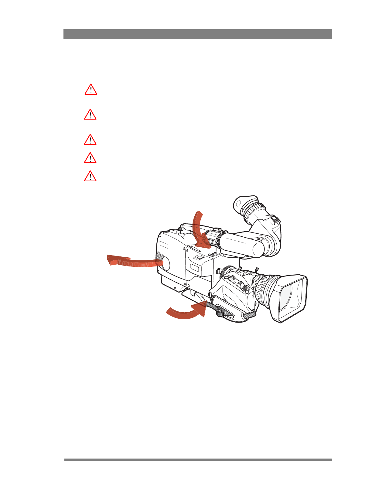
To prevent risk of overheating, ventilate the camera correctly. Do not block the hot airflow
coming from the outlet on the right side of the camera adapter.
Page 10

10 Focus 70 Live Highly Affordable HD System Camera User’s Guide (v1.1)
Precautions
To ensure continual high performance from the camera take the following precautions into
consideration:
• Avoid damp places. If the environment is wet or damp a rain cover must be used to
protect the unit.
• Do not subject the unit to severe shocks or vibration.
• Do not expose the camera to extremes of temperature.
• Do not leave the unit in direct sunlight or close to heating appliances for extended periods.
• Do not allow sunlight to shine into the viewfinder.
• Do not allow laser beams to shine into the lens as this could damage the imagers.
• Avoid extreme highlights as these can cause various kinds of optical reflections.
• Be careful when connecting and disconnecting Triax or Fiber cables.
• Do not connect Grass Valley camera systems with other manufacturer’s camera system
parts.
• Make connections swiftly and firmly to avoid false error messages.
Page 11

Focus 70 Live Highly Affordable HD System Camera User’s Guide (v1.1) 11
Triax cable systems
Do not allow system earth currents to exceed 1.5 A in the outer shield of the Triax cable or 0.2
A in other cable shields.
To avoid excessive earth currents in a Triax system, galvanically separate the power earth
connection of equipment connected to the camera from the camera earth.
It is strictly prohibited to short circuit the inner and outer shields of a Triax cable used to
connect a camera to an XCU.
Galvanic separation
Because of the nature of Triax systems, with long distances between camera and its XCU, the
risk of earth currents flowing is greater. These earth currents can result in damage to the
equipment.
For example, a monitor connected directly to the monitor output of the camera is powered
locally. The earthing point of the monitor’s power supply can be at a different potential with
respect to the earthing point of the XCU. If the power earth of the monitor is also the video
earth, then this earth potential is transferred to the camera via the shield of the BNC connector.
The difference in earth potential between the camera and the XCU results in an earth current in
the Triax system.
To prevent earth currents from flowing in the Triax system, we recommend galvanic separation
of earthed equipment connected to the camera. This separation can be achieved by using an
isolation transformer between the local power outlet and the equipment connected to the
camera. Alternatively, use equipment that has a double insulation and therefore does not
require an earth connection.
Page 12
12 Focus 70 Live Highly Affordable HD System Camera User’s Guide (v1.1)
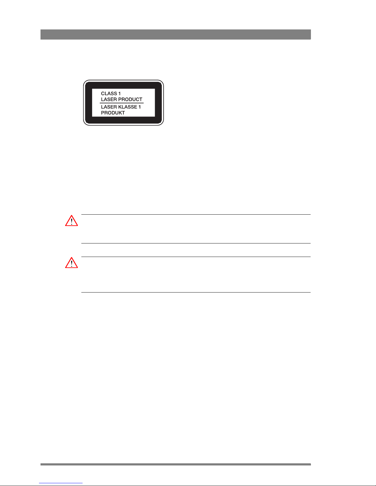
Fiber-optic transmission units
Laser safety statement (for Europe)
Fiber-optic transmission units are classified as a “Class 1 Laser Product” according to
EN
60825-1, Safety of Laser products. CLASS 1 laser products are considered safe and do not
result in biological hazard if used according to the instructions.
Laser safety statement (for US)
Fiber-optic transmission units are ified as a “Class 1 Laser Product” according to
21CFR
1040.10 of the US Food and Drug Administration (FDA) Center for Devices and
Radiological Health.
WARNING
Use of controls, adjustments or performance of procedures other than those specified herein
may result in hazardous radiation exposure.
WARNING
To ensure proper use of this product, please read this instruction manual carefully and retain
for future reference. Should the unit ever require maintenance, contact an authorized service
location.
Fiber-optic cable precautions
Fiber-optic cables and connectors are easily damaged; take the following precautions into
account:
• Do not bend the cable beyond the minimum permissible bend range specified for the
cable.
• Avoid kinks in the cable.
• Avoid subjecting the cable to a high tension force (even momentarily).
• Do not twist the cable when connecting it to equipment.
• Insert connectors straight and fully into their corresponding sockets.
• In fiber-optic cable systems always put the dust caps on cable and panel connectors
immediately after disconnecting a cable. Keep the dust caps clean.
Page 13

Focus 70 Live Highly Affordable HD System Camera User’s Guide (v1.1) 13
Cleaning fiber-optic connectors
WARNING
Always switch off power before cleaning the connectors.
WARNING
Never clean an optical connector attached to a fiber that is carrying light.
Particles of foreign matter on the tip of a ferrule can have a disabling effect on fiber-optic
transmission. Fiber-optic connectors need to be cleaned every time they are mated and
unmated; it is essential that fiber-optic users develop the necessary discipline to always clean
the connectors before they are mated.
Use a commercially available cleaning kit specifically designed for fiber-optic connectors and
follow the manufacturer's instructions carefully.
• The connector sections to be cleaned include the tips and sides of ferrules, the interior
walls of alignment sleeves, and the interior and exterior of connector shells.
• For plugs, the interior surfaces of alignment sleeves and the tips of ferrules are to be
cleaned with a cleaning stick treated with the appropriate fluid. (Cleaning sticks with a
slender design are available that allow alignment sleeves to be cleaned without having to
detach them.)
• For jacks, it is important to clean both the tips and sides of the completely protruding
ferrules.
• Both the male and female connector shells tend to attract dust and metal particles, so it is
important to clean both the insides and outsides.
• The fiber end face and ferrule must be absolutely clean before it is inserted into a
transmitter or receiver.
• Mate the connector immediately! Don't let the connector lie around and collect dust
before mating.
• Air can be used to remove lint or loose dust from the port of a transmitter or receiver to be
mated with the connector. Never insert any liquid into the ports.
Page 14

14 Focus 70 Live Highly Affordable HD System Camera User’s Guide (v1.1)
Page 15

Focus 70 Live Highly Affordable HD System Camera User’s Guide (v1.1) 15
Chapter 1 - Introduction
Chapter 1
Introduction
1.1 Welcome
The Focus 70 Live is a professional and affordable, single-format system camera that uses
Xensium-FT CMOS imagers. A Focus 70 Live camera head contains optics, imagers and digital
image processing electronics, while the transmission system (Fiber or Triax) can be selected
by docking an interchangeable transmission adapter to the camera head.
This makes Focus 70 Live cameras ideal for smaller live studio and field applications, including
regional broadcast stations, SNG vans, small OB vans, university sports productions, staging
and houses of worship.
1.1. 1 About this guide
The purpose of this guide is to present a detailed description of how to operate an Focus 70
Live camera head equipped with a dockable transmission adapter. It provides the information
necessary to use the camera in different configurations and with various attachments. This
guide describes all operating features of the camera so it can be used to its full potential.
This guide is so designed that it can be used as an introduction to those who are new to the
camera, as a simple procedural guide to those who wish to set-up and start shooting
immediately, and as a reference work to be consulted as required during the long life of the
camera.
1.1. 2 Related documents
Before proceeding, check the Grass Valley website at www.grassvalley.com for the latest
version of this user’s guide and additional information:
• User’s guide updates, data sheets, brochures and application notes.
• Camera software updates, release notes and installation instructions.
Page 16

16 Focus 70 Live Highly Affordable HD System Camera User’s Guide (v1.1)
Chapter 1 - Introduction
1.2 Technology
1.2. 1 Xensium-FT imagers
The Focus 70 Live camera head uses Grass Valley’s custom-designed 2/3-inch CMOS
Xensium-FT imagers that offer superior performance and ultimate flexibility. Native highdefinition video formats 1080i or 720p (depending on the camera model) are produced at the
touch of a button.
The Xensium-FT imagers with global shutter— similar to CCD sensors — do not produce any
of the rolling shutter artifacts seen with other CMOS based cameras, such as sensitivity to fast
camera movements with short exposure time or sensitivity to short light flashes.
Xensium-FT imagers have a high dynamic range and high linear sensitivity across all lens
apertures.
1.2. 2 Camera models
The Focus 70 Live camera is available in two different models: the Focus 70 Live 720p and the
Focus 70 Live 1080i.
1.2. 3 Superior digital processing
The advanced video processing of the camera is done with floating point precision while all
major camera functions are processed in the digital domain, including knee, gamma, detail,
matrix and color correction.
Chromatic lens aberration correction (CLASS) offers impressive sharpness improvements on
the outer regions of the image by canceling out shifts in color registration. This algorithm
works in conjunction with lens data, using industry standard lens interface protocols.
The Focus 70 Live provides enhanced colorimetry, color matching, and picture performance.
Color temperature and tint are just two of the parameters that can be simultaneously adjusted
across multiple cameras.
1.2. 4 Designed for the operator
The Focus series offers even more operational excellence. Button layouts as well as control
knobs are ergonomically designed to allow the operator to find the right adjustments easily.
Full control flexibility is possible thanks to well dimensioned control knobs. With the easily
accessible separated info button, operational information can de displayed in the viewfinder
instantaneously.
The user-friendliness of Focus series cameras has been further improved by using a
streamlined camera menu structure that allows operators to access commonly used functions
more quickly. The camera menu is arranged around operational, video setup, creative setup
and system configuration.
Another imaging innovation is ArtTouch™, an intuitive interface between the operator and hard
wired controls, which significantly enhances artistic possibilities during live broadcast.
ArtTouch includes smart coupling of video control functions.
Page 17

Focus 70 Live Highly Affordable HD System Camera User’s Guide (v1.1) 17
Chapter 1 - Introduction
1.3 Key features
• Fully digital Xensium-FT CMOS imagers with global shutter operation offer absolute
smear-free images under all conditions.
• Best possible resolution and image sharpness from oversampling the full HD progressive
image.
• Highest sensitivity in combination with the best noise performance for the best results,
even under difficult lighting conditions.
• Highest quality mechanical construction identical to high-end Grass Valley LDX Series
broadcast camera systems.
1.4 List of accessories
Viewfinders
EyeCatcher EC 270 2.7-inch LCD HD color ocular viewfinder
EyeCatcher EC 744 7.4-inch OLED Viewfinder
LDK 5307 7-inch LCD HD color viewfinder
LDK 5309/10 9-inch LCD HD color viewfinder
Accessories
LDK 5341 ComfortPad shoulderpad
LDK 5031/10 Tripod plate
LDK 8111/37 Dynamic headset (double muff) with XLR-5 connector
LDK 8111/51 Dynamic headset (single muff) with XLR-5 connector
LDK 6985/30 Universal camera script board
LDK 5020/05 Universal transport case
LDK 5020/01 Carrying bag
Page 18

18 Focus 70 Live Highly Affordable HD System Camera User’s Guide (v1.1)
Chapter 1 - Introduction
Page 19
Focus 70 Live Highly Affordable HD System Camera User’s Guide (v1.1) 19
Chapter 2 - Installation
Chapter 2
Installation
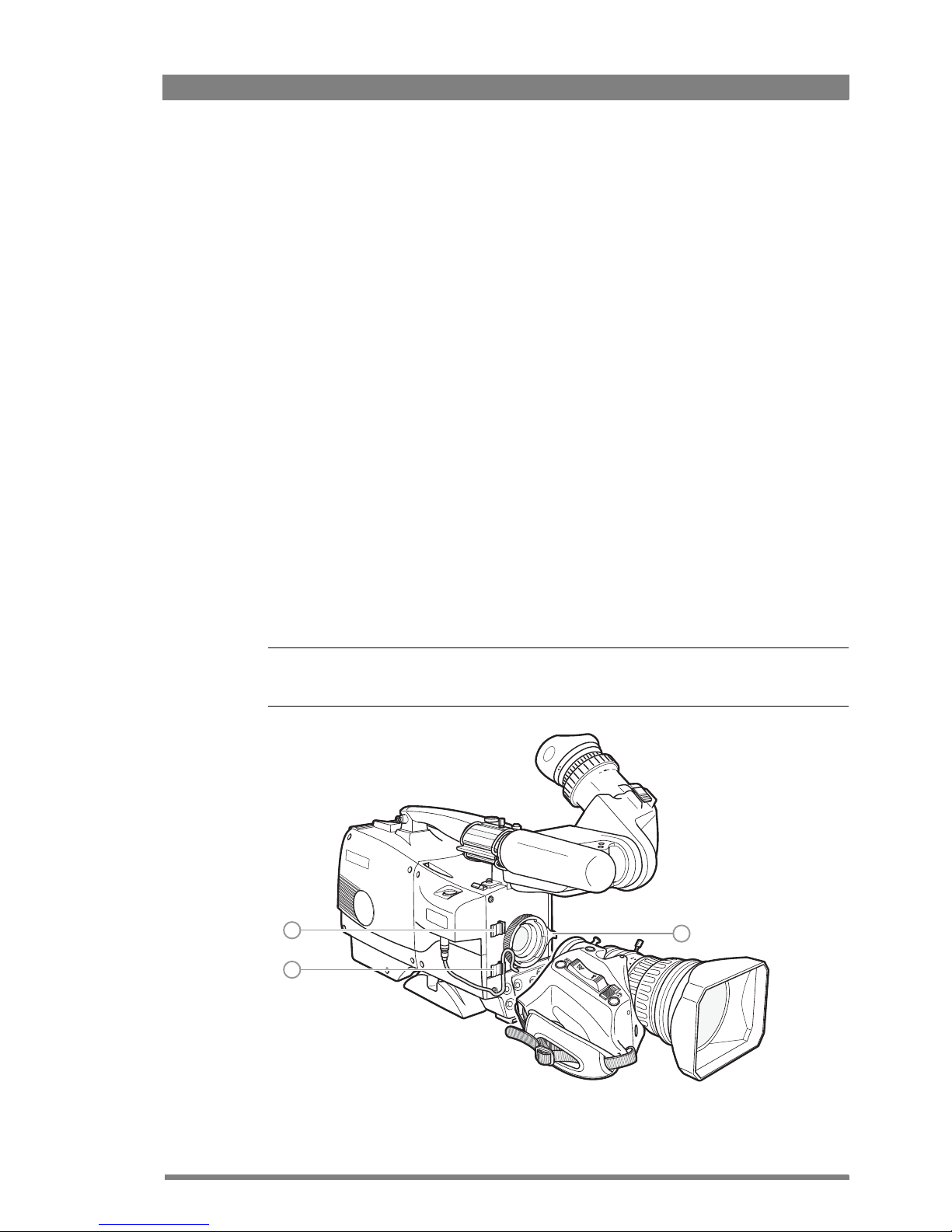
2.1 Mounting a lens
To attach a lens to the camera head proceed as follows:
1. Ensure that the lens locking ring (1) is in the unlocked position (turned counterclockwise).
2. If present, remove the dust protection cap.
3. Slot the lens into the lens mount.
4. Turn the lens locking ring (1) clockwise until the lens locks firmly in place.
5. Connect the lens cable to the lens connector at the right side of the camera.
Tip
✎
Use the clips (2) on the front of the camera to guide the lens cable along the camera body.
1
2
2
Page 20
20 Focus 70 Live Highly Affordable HD System Camera User’s Guide (v1.1)
Chapter 2 - Installation
Caution
Do not attach a lens weighing more than 5 kg (11 lbs) to the camera without a proper lens
support.
When a new lens is fitted to the camera it may be necessary to carry out some adjustments to
optimize its use, for example, back focus or shading. For more information about these
adjustments refer to the lens manufacturer’s documentation.
☞
Note
☞
Note
Always mount the dust protection cap when the lens is not connected to the camera.
2.2 EC 270 EyeCatcher viewfinder
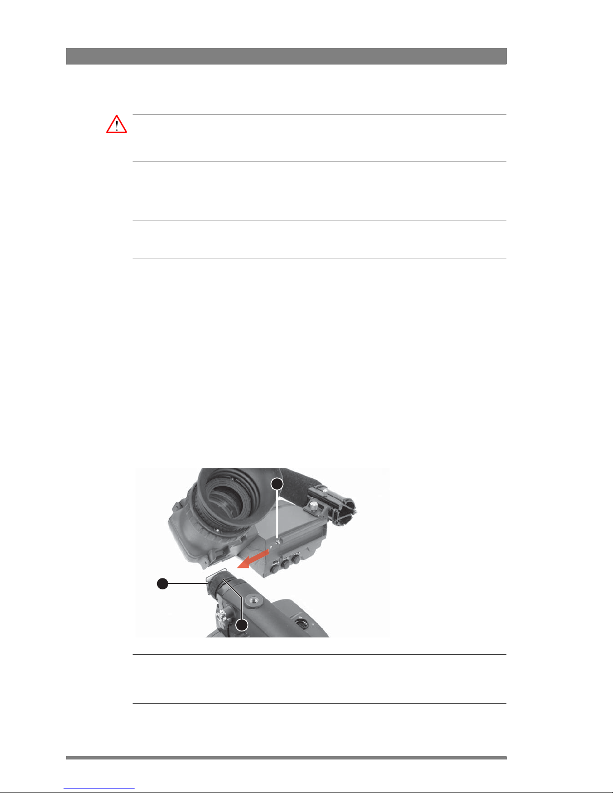
2.2.1 Mounting the viewfinder
To mount the viewfinder proceed as follows:
• Loosen locking ring (2) of viewfinder support bracket (1) at the front of the camera
handgrip. (As seen from the rear of the camera, turning the locking ring counterclockwise
moves it towards the handgrip.)
• Push the locking pin (3) in and slide the viewfinder onto the viewfinder support bracket (1).
• Tighten the locking ring (2) by turning it clockwise (as seen from rear) so that the
viewfinder is mounted securely to the support.
Tip
✎
To improve the comfort of the skin contact when using the viewfinder, fit the eye piece cover
to the rubber eyepiece. Spare covers are available via your Grass Valley representative.
3
1
2
Page 21
Focus 70 Live Highly Affordable HD System Camera User’s Guide (v1.1) 21
Chapter 2 - Installation
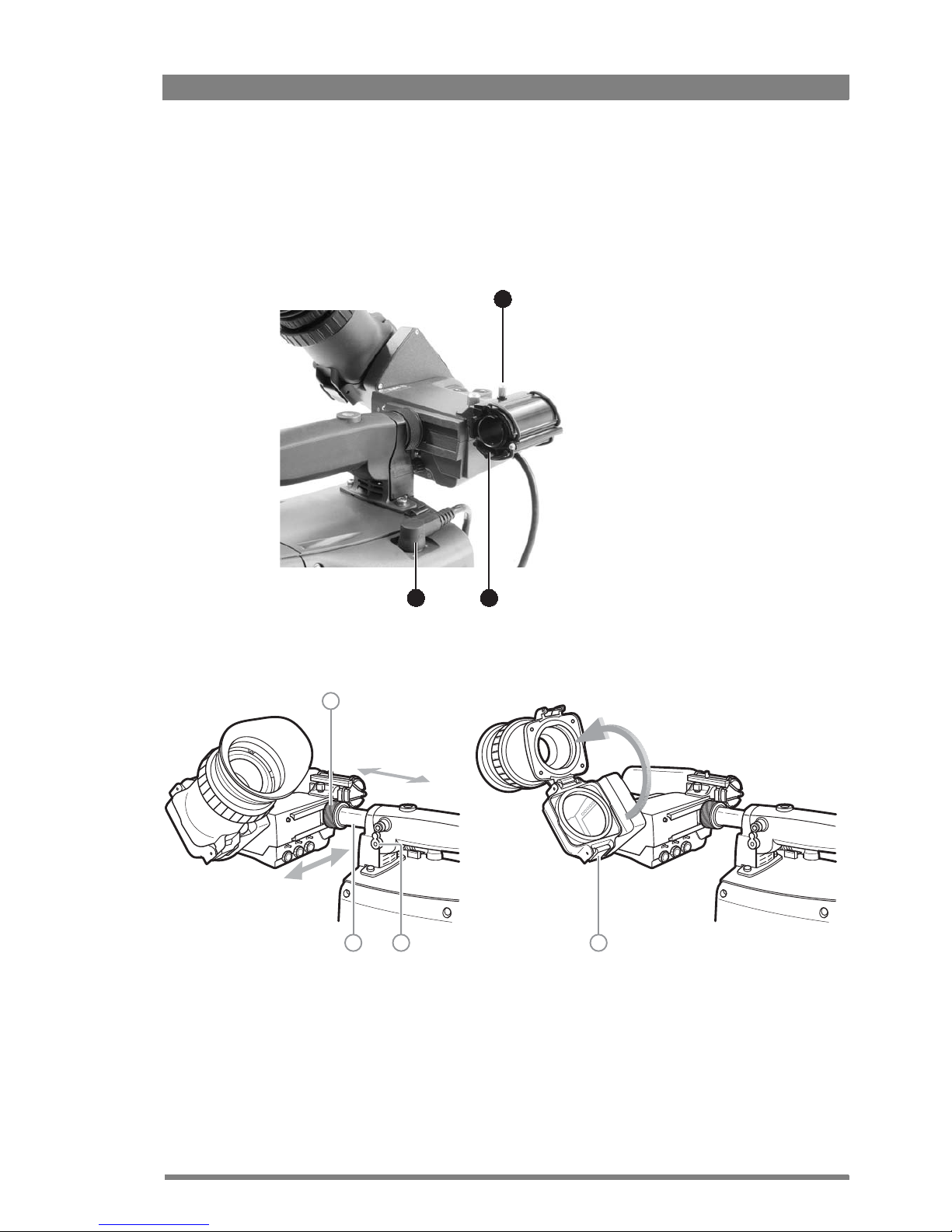
• Connect the viewfinder cable to the viewfinder socket (1) at the top right of the camera.
• Attach the microphone holder (2) onto the viewfinder and secure it with the knurled screw
(3).
• Guide the viewfinder cable along the front of the camera and attach it to one of the cable
clips.
2.2.2 Positioning the viewfinder
The horizontal position of the viewfinder can be adjusted as follows to suit your requirements:
• Loosen the locking ring (1). As seen from the rear of the camera, turning the locking ring
counterclockwise moves it towards the handgrip.
• Slide the viewfinder horizontally along the rail to the desired position.
• Tighten the locking ring (1) by turning clockwise.
1
3
2
1
2 3 4
Page 22
22 Focus 70 Live Highly Affordable HD System Camera User’s Guide (v1.1)
Chapter 2 - Installation
The viewfinder can be positioned backwards and forwards along the camera axis:
• Loosen the support bracket round bar retaining lever (3).
• Slide the round bar (2) forwards or backwards.
• When the desired position is reached tighten the round bar retaining lever (3) again.
The viewfinder can also be viewed from a distance :
• Press the bottom clip (4) below the eyepiece and swing it free of the associated clip.
• The eyepiece can also be swung downwards; press the top clip to release the eyepiece
and swing it downwards.
☞
Note
☞
Note
Handle the eyepiece with care when folded back—its position is not secured.
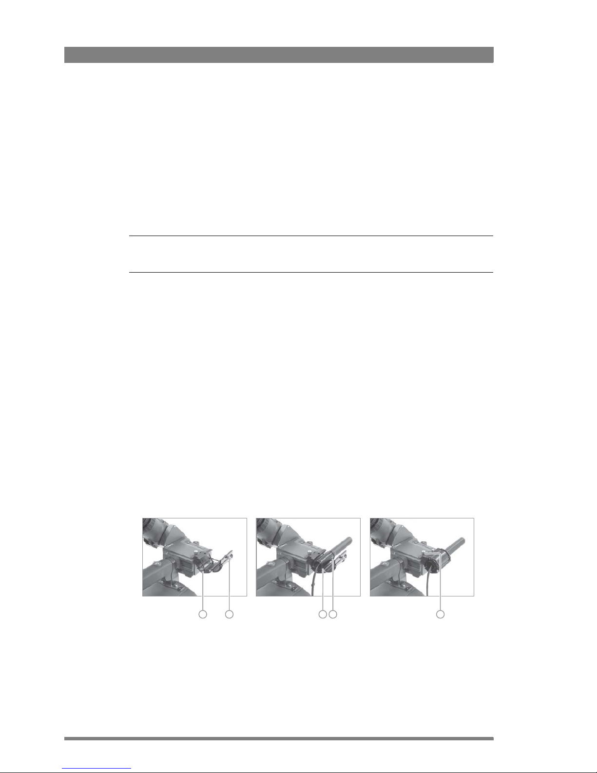
2.3 Attaching a microphone
To attach the optional microphone to the camera proceed as follows:
1. Open the microphone holder by unscrewing the knurled screw (1) of the microphone
support bracket (2) on the viewfinder and open.
2. Slide the microphone into the split tube until the microphone shoulder reaches the mark in
the tube (about half way in).
3. Place the tube with the microphone into the holder with the split facing upwards. Mount
the microphone as straight as possible.
4. Ensure that the rubber supports at the back and front of the holder fit into the rims (3)
around the tube.
5. Close the holder and tighten the knurled screw at the top (4). Don’t allow the wind hood to
touch the holder as this reduces the damping effect.
6. Connect the microphone cable to the MIC audio XLR connector on the right side of the
camera. To avoid mechanical pick-up, do not let the microphone cable touch the holder.
Other microphones with a diameter of 21 mm (0.83 in) can also be used, however, ensure that
the sensitivity of the input that match that type of microphone are correctly selected in the
camera CONFIGURATION menu. When a longer microphone is used, it is not necessary to
place it in the split tube. Phantom power is always present on the front microphone socket.
2 1 33 4
Page 23
Focus 70 Live Highly Affordable HD System Camera User’s Guide (v1.1) 23
Chapter 2 - Installation
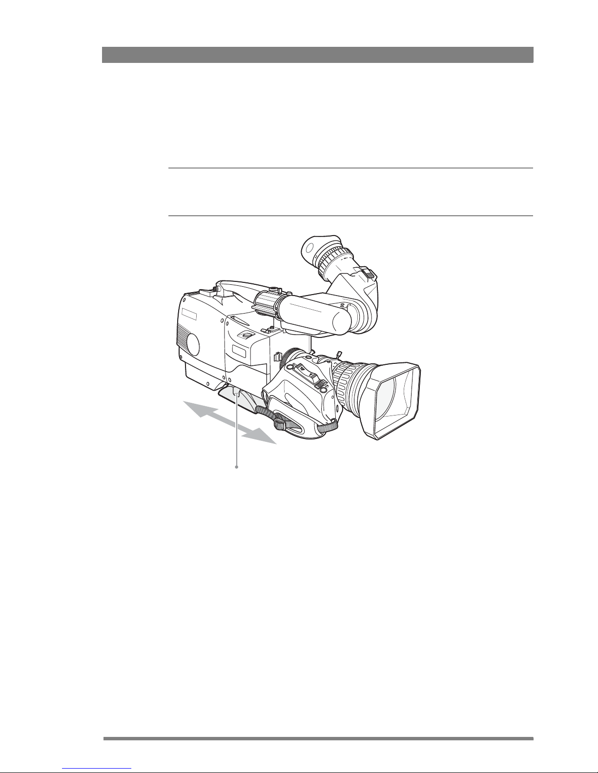
2.4 Adjusting the shoulder pad
To change the position the shoulder pad press and hold the adjustment lever at the bottom left
of the camera body. The shoulder pad can now be moved backwards and forwards along the
axis of the camera.
Tip
✎
Adjust the shoulder pad when all units have been mounted to get the best balanced shoulder
position.
Shoulder pad
adjustment lever
Page 24
24 Focus 70 Live Highly Affordable HD System Camera User’s Guide (v1.1)
Chapter 2 - Installation
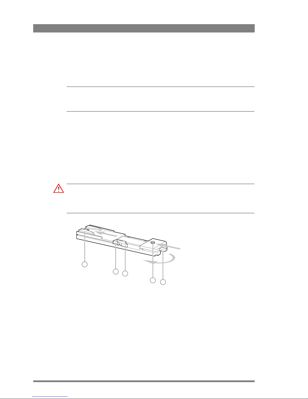
2.5 Mounting the camera onto a tripod plate
To mount the camera on a tripod, the LDK 5301/10 tripod adapter plate must first be attached
to the tripod. Follow the tripod manufacturer’s instructions to mount the wedge plate supplied
with the tripod and the tripod adapter plate firmly onto the tripod.
☞
Note
☞
Note
Before proceeding make sure that the shoulder pad is in the back position. Refer to Section 2.4
on page 23 how to do this.
Attach the camera to the tripod adapter plate as follows:
1. Slide the camera horizontally along the tripod adapter plate from back to front ensuring
that the front of the camera engages the V-slot (1) at the front of the tripod adapter plate,
and that the slot on the bottom of the camera engages the stud (2) at the rear of the tripod
adapter plate.
2. Firmly push the camera forward until it clicks into place.
3. When the camera is mounted firmly, the locking lever (5) swings around fully to the rear of
the plate. If the lever does not travel the full distance, you should manually lock it into
place.
Caution
Failure to attach the camera to the tripod adapter plate in the correct manner could result in an
unsecured camera. Ensure that the rear stud (2) is engaged and that the camera clicks into
place.
Remove the camera from the tripod as follows:
1. Open the locking lever (5) to free the rear stud (2).
2. Press and hold the red locking lever (3) against the release handle (4).
3. Ensure that you have a firm hold of the camera.
4. Pull the release handle (4) forward.
5. Move the camera backwards and up.
2
3
4
1
5
Page 25
Focus 70 Live Highly Affordable HD System Camera User’s Guide (v1.1) 25
Chapter 2 - Installation
2.6 Exchanging the camera adapter
2.6.1 Preparation
• Exchange the adapter in a safe area, preferably indoors. Make sure your working area is
clean and dust free.
• Remove all accessories (microphone, viewfinder, lens and cables) before exchanging the
camera adapter.
• For the exchange procedure a Torx T20 size screwdriver is needed.
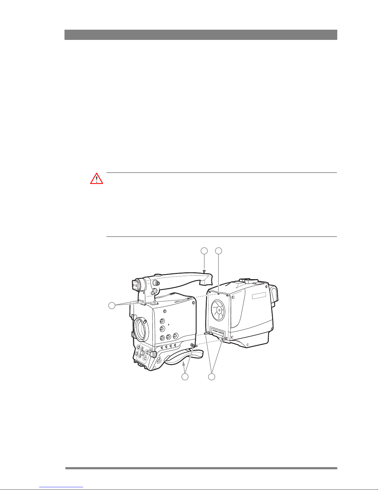
2.6.2 Attaching the adapter
Caution
Be extremely careful with the connectors between the camera head and the adapter. Do not
allow the metal guide pins to damage the pins of the docking connector.
Do not touch the uncovered blades of the cooling fan of the adapter.
Follow the indicated steps in the indicated order. Tightening or loosening the screws in the
wrong order could result in mechanical damage to the camera and/or the adapter.
To attach the adapter to the camera head proceed as follows:
1. Fit the guide pin at the top rear of the camera head into the corresponding slot of the
adapter and at the same time fit the guide pins on either side of the docking connector
into the corresponding slots [1] of the camera.
2. Carefully press camera head and adapter together at the bottom and tighten the two
screws [2] at both sides of the camera head.
14
2 1
3
Page 26

26 Focus 70 Live Highly Affordable HD System Camera User’s Guide (v1.1)
Chapter 2 - Installation
3. Tighten the two screws [3] at the top of the camera head.
4. Tighten the vertical top screw [4] in the handgrip of the camera head.
2.6.3 Detaching the adapter
To detach the adapter from the camera head proceed as follows:
1. Loosen the vertical top screw [4] in the handgrip of the camera head.
2. Loosen the two screws [3] at the top of the camera head.
3. Loosen the two bottom screws [2] at both sides of the camera head.
4. Carefully disconnect the adapter from the camera head.
2.7 LDK 5020/05 Universal Transport Case
Both your camera and its accessories are sensitive equipment, so it is important to protect
these against damage when transporting it. To do this, a universal transport case is optionally
available for the camera, lens, viewfinder and some accessories.
Turn the EC 270 viewfinder ocular downwards so that it does not protrude above the top of the
camera.
Several foam packing inserts are provided to enable different configurations of the camera to
be packed securely. These inserts are used to support the rear of the camera. Make sure you
use the correct foam inserts for your particular configuration.
Caution
To prevent damage always detach the lens from the camera head before transporting.
2.8 Packing for return
If a unit is being returned to Grass Valley for servicing, try to use the containers and materials
of the original packaging. Attach a tag indicating the type of service required, return address,
model number, full serial number and the return number which will be supplied by your Grass
Valley service centre.
If the original packing can no longer be used, the following general instructions should be used
for repacking with commercially available materials:
1. Wrap unit in heavy paper or plastic.
2. Use strong shipping container.
3. Use a layer of shock-absorbing material around all sides of the unit to provide firm
cushioning and prevent movement inside container.
4. Seal shipping container securely.
5. Mark shipping container FRAGILE to ensure careful handling.
Page 27
Focus 70 Live Highly Affordable HD System Camera User’s Guide (v1.1) 27
Chapter 3 - Configurations
Chapter 3
Configurations
3.1 Transmission systems
Grass Valley’s Focus transmission system is based on digital transmission and a new, robust
power system. The system consists of a dockable camera adapter that fits on a Focus 70 Live
camera head and a Focus Base Unit that takes care of power, signal transport and connection
to the studio or OB van.
Two different transmission systems are available for the Focus 70 Live camera head: Triax and
Fiber. Due to the versatile dockable concept, camera adapters can be easily exchanged to
match the existing transmission infrastructure.
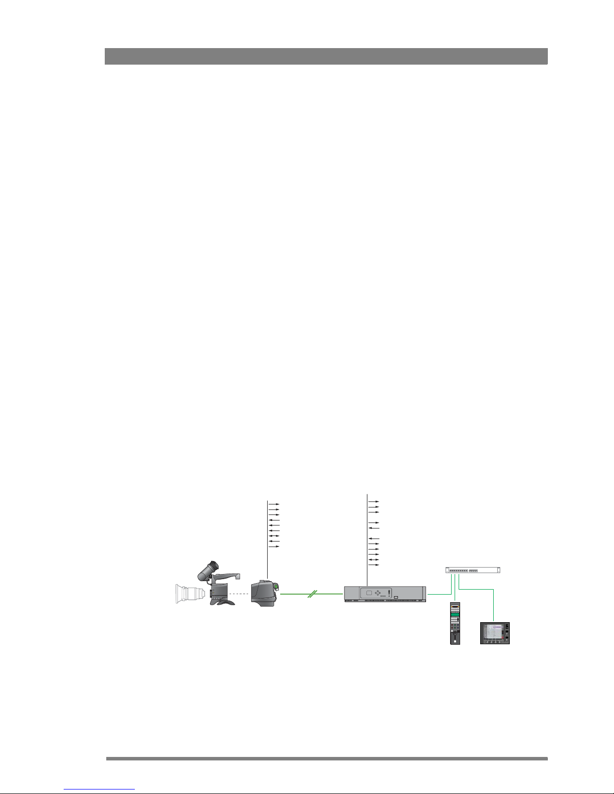
3.2 Triax configuration
The Triax transmission system is the perfect interface between your Focus 70 Live camera and
the rest of your system. It offers video and signal transmission and remote control of cameras
up to a distance of 1,500 m (5,000 ft) using industry standard Triax cables.
Master Black
USB
Iris
34
F4.5
RE
HD-SDI (3 Gb/1.5 Gb) out (Main)
VF Out
EXT video out
EXT video in
Analog audio in (2 ch.)
Front mic in
Intercom headset I/O
Reference in
Teleprompter out
SD-SDI out (2x)
HD-SDI (1.5 Gb) out (2x)
HD-SDI (3 Gb/1.5 Gb) out (6x)
Text out
Tally signal
Intercom I/O
EXT video in (3x)
SD-RGB/YUV/SDI out
Analog audio out (2 ch.)
Digital Audio out (2x 2 ch.)
Monitoring out
Focus Triax
adapter
OCP 400 MCP 450
Focu s Triax
Base Unit
Focus 70 Live
camera head
C2IP Camera Control
Ethernet infrastructure
Page 28
28 Focus 70 Live Highly Affordable HD System Camera User’s Guide (v1.1)
Chapter 3 - Configurations
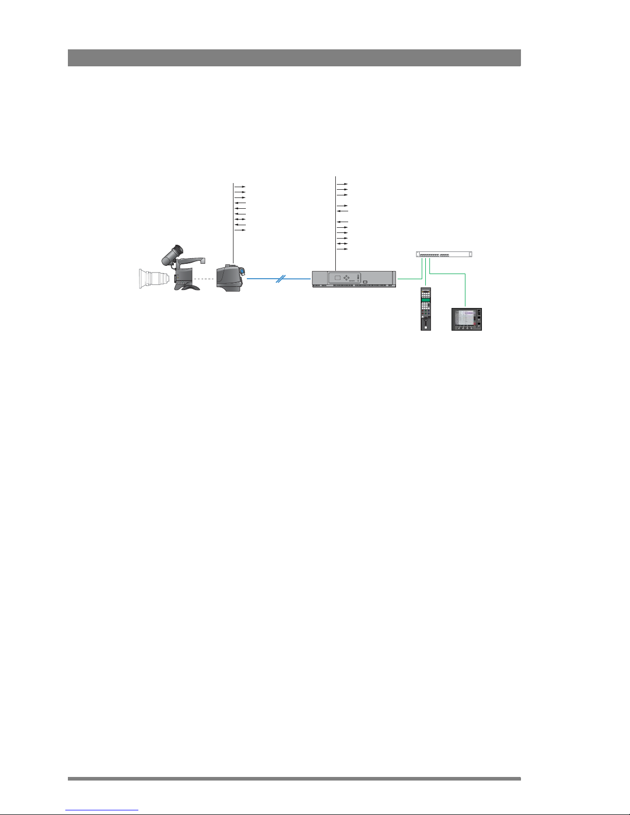
3.3 Fiber configuration
The Fiber transmission system is the perfect interface between your Focus 70 Live camera and
the rest of your system. It offers video and signal transmission and remote control of cameras
up to a distance of 3,000 m (10,000 ft) using hybrid fiber cables.
Master Black
USB
Iris
34
F4.5
RE
HD-SDI (3 Gb/1.5 Gb) out (Main)
VF Out
EXT video out
EXT video in
Analog audio in (2 ch.)
Front mic in
Intercom headset I/O
Reference in
Teleprompter out
SD-SDI out (2x)
HD-SDI (1.5 Gb) out (2x)
HD-SDI (3 Gb/1.5 Gb) out (6x)
Text out
Tally signal
Intercom I/O
EXT video in (3x)
SD-RGB/YUV/SDI out
Analog audio out (2 ch.)
Digital Audio out (2x 2 ch.)
Monitoring out
Focus Fiber
adapter
OCP 400 MCP 450
Focus Fiber
Base Unit
Focus 70 Live
camera head
C2IP Camera Control
Ethernet infrastructure
Page 29

Focus 70 Live Highly Affordable HD System Camera User’s Guide (v1.1) 29
Chapter 4 - Operating instructions
Chapter 4
Operating instructions
4.1 Using the camera
Attach a lens, viewfinder, microphone to the camera. Attach the Fiber or Triax cables.
4.1.1 Powering the camera
The power supply for the camera and its adapter is supplied via the Triax or hybrid fiber cable
from the Base Unit. The Power On indicator lights when power is supplied and the camera
power switch is set to the on position .
If excessive current flows in the camera or adapter, the internal safety circuit shuts off power
to all the units. If this happens shut off power and check the units for faults and if necessary
take corrective actions before switching on power again.
4.1.2 Switching on
1. On the Base Unit set the power switch to the on position (I). The green power indicator on
the Base Unit lights.
2. Set the camera power switch of the camera to the on position .
3. Allow a few moments for the camera to perform a self-test and for the system to
establish communications. The startup process can be monitored on the indicator panel of
the Base Unit.
To switch the camera to stand-by, set the power switch of the camera to the position.
Page 30
30 Focus 70 Live Highly Affordable HD System Camera User’s Guide (v1.1)
Chapter 4 - Operating instructions
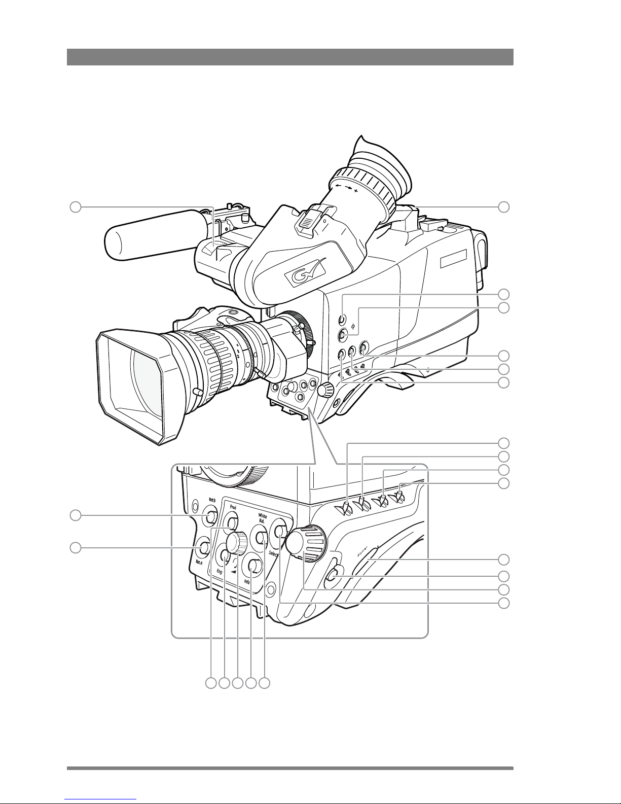
4.2 Location of controls (front)
1
22
21
8
9
10
11
12
13
14
15
2
6
5
3
4
7
20 19 18 17 16
Page 31

Focus 70 Live Highly Affordable HD System Camera User’s Guide (v1.1) 31
Chapter 4 - Operating instructions
[1] Front Tally lamp
Lights when the camera is On Air.
[2] Rear Tally lamp
Lights when the camera is On Air.
[3] Filters button
Press to enter the filter selection menu and
select neutral density (ND) and/or effects (FX)
optical filters.
[4] PickMe button
Press to send an attention signal to the studio
back room.
[5] Standard Recall (Green) button
Press and hold two seconds to recall
standard values for the camera.
[6] User button SW2
Assignable button SW2.
[7] User button SW1
Assignable button SW1.
[8] Gain selection switch
Move up or down to select a Gain preset or
hold to set a variable gain value.
[9] Color bar switch
Switches the color bar on or off.
[10] Color temperature switch
Move up or down to select a color
temperature preset or hold to vary.
[11] Exposure time switch
Move up or down to select an exposure time
or hold to set a variable exposure time.
[12] Power switch
Main camera power switch.
[13] Menu Back button
Used when navigating the camera menu.
[14] Menu Rotary control
Used when navigating the camera menu.
[15] Menu Select button
Used when navigating the camera menu.
[16] White Balance button
Press and hold two seconds to start the Auto
White Balance procedure.
[17] Info button
Press and hold to view information on the
viewfinder screen.
[18] Headset volume control
Adjusts the overall audio volume of the
intercom headset.
[19] Intercom Eng button
This button is used to activate the intercom
Production channel.
[20] Intercom Prod button
This button is used to activate the intercom
Production channel.
[21] Return A button
This button can be assigned to an External
Video channel.
[22] Return B button
This button can be assigned to an External
Video channel.
Page 32
32 Focus 70 Live Highly Affordable HD System Camera User’s Guide (v1.1)
Chapter 4 - Operating instructions
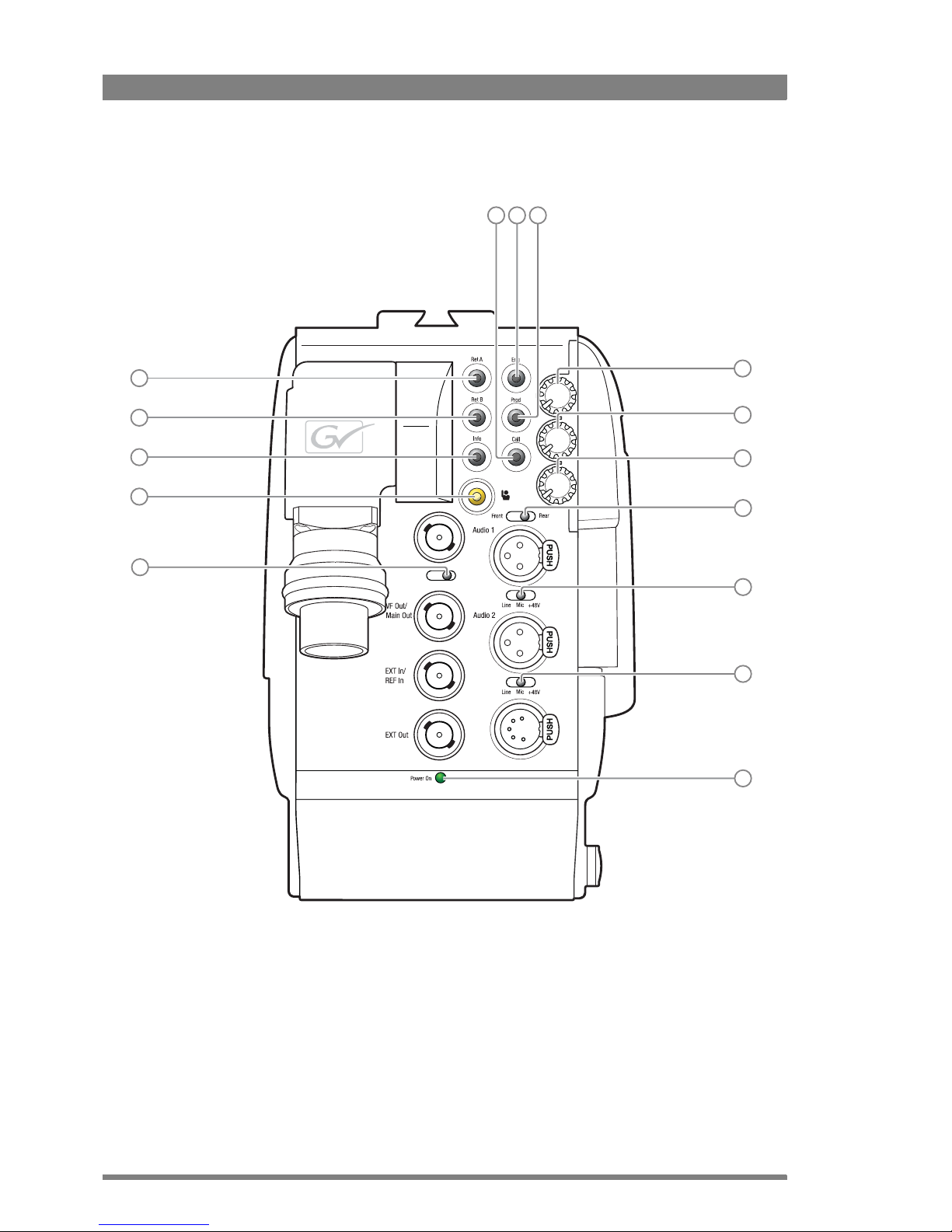
4.3 Location of controls (back panel)
An VF Out
TP
Prod
Prog
Eng
Analog
VF Out/
TP
1
2
3
4
5
6 7 8
9
10
11
12
13
14
15
Page 33

Focus 70 Live Highly Affordable HD System Camera User’s Guide (v1.1) 33
Chapter 4 - Operating instructions
[1] Return A
This button can be assigned to an External
Video channel.
[2] Return B
This button can be assigned to an External
Video channel.
[3] Info button
Press and hold to view information on the
viewfinder screen.
[4] PickMe button
Press to send an attention signal to the studio
back room.
[5] An VF Out/TP switch
Analog VF/Teleprompter connector selection
switch.
[6] Call button
Call button.
[7] Intercom Eng button
This button is used to activate the intercom
Engineering channel.
[8] Intercom Prod button
This button is used to activate the intercom
Production channel.
[9] Intercom Prod volume
Intercom headset volume (Production).
[10] Intercom Prog volume
Intercom headset volume (Program).
[11] Intercom Eng volume
Intercom headset volume (Engineering).
[12] Front/Rear switch
Select Audio 1 routing.
[13] Audio 1 switch
Mode selection switch for Audio 1 connector.
[14] Audio 2 switch
Mode selection switch for Audio 2 connector.
[15] Power on indicator
Power on indicator.
Page 34

34 Focus 70 Live Highly Affordable HD System Camera User’s Guide (v1.1)
Chapter 4 - Operating instructions
4.4 Controlling the camera
There are several ways to control the camera:
• Using the operational switches on the camera;
• Using the camera menu to select functions;
• Using an Operational Control Panel (OCP 400) connected to the C2IP network or Base
Unit;
– Refer to the OCP 400 User’s Guide for detailed operating instructions for the OCP 400.
• Using a Master Control Panel (MCP 450) connected to the C2IP network or Base Unit;
☞
Note
☞
Note
If you cannot access some camera functions or you wish to restrict access, refer to “Access
and security” on page 54.
4.4.1 Navigating the camera menu
The camera menu can be viewed in the viewfinder (or connected monitors) and navigated by
means of the rotary control and the select and back buttons which are located at the front and
left of the camera:
The functions of the camera are grouped into a structure of menus and sub-menus. Each of the
menus gives you access to a particular group of functions. Spend some time using the controls
and menus to discover the various functions. You will quickly learn to operate the camera
intuitively.
☞
Note
☞
Note
Some of the menu items may not appear if the user level is not set to 3.
Menu select
button
Menu rotary
control
Menu back
button
Page 35

Focus 70 Live Highly Affordable HD System Camera User’s Guide (v1.1) 35
Chapter 4 - Operating instructions
4.4.2 Entering the camera menu
Press the select button after the camera is switched on, the message MENU OFF appears in the
viewfinder. Press the select button again while this text is showing, the MAIN menu appears in
the viewfinder.
The MAIN menu screen shows five items. The name of the menu is shown below these. More
items are hidden but become visible when you scroll down using the rotary control. The
cursor shows your position in the menu. The rotary control moves the cursor up and down.
4.4.3 Finding your way
Use the rotary control to move the cursor through the menu items. If a double arrow (>>) is
visible, then pressing the select button brings you one level lower in the menu system. Only
five items are visible in each menu. Scroll up or down to see any additional items. When you
first enter a menu (other than the MAIN menu) the cursor is positioned next to the first item.
Press the back button to go back to the menu that you were in before the current one. The
cursor is positioned next to the last menu.
You can also use the TOP and PREVIOUS items to navigate. These items are not immediately
visible but are located above the first item. Use the rotary control to scroll up to them.
• Select TOP to bring you back to the MAIN menu.
• Select PREVIOUS to go back to the menu that you were in before the current one.
The PRODUCTION SETUP menu, for example, shows the items displayed when you first enter
the menu. The other items are available by scrolling up or down with the rotary control.
Menu Off
Operator Toolbox
Production Setup
Creative Control
Configuration
Main
Exec
>>
>>
>>
>>
Diagnostics >>
Levels
Exposure
Color
Image Control
Files
Production Setup
>>
>>
>>
>>
>>
Video Mode
Sensitivity
720p50
Nom
TOP
PREVIOUS
Page 36

36 Focus 70 Live Highly Affordable HD System Camera User’s Guide (v1.1)
Chapter 4 - Operating instructions
4.4.4 Leaving the camera menu
If you are deep within the menu structure, the recommended way of leaving the menu is to
press the back button a number of times until the menu is abandoned. You can also navigate to
leave the menu:
1. If necessary move the cursor to the left column with the select or back button.
2. Scroll upwards with the rotary control until the cursor points to TOP (the MAIN menu).
3. Press the select button. The cursor now points to the MENU OFF item of the MAIN menu.
4. Press the select button again to leave the camera menu.
If you do not use the menu it disappears after a few seconds. This delay can be programmed in
the OPERATOR TOOLBOX menu. You can also press and hold the or back button for 2 seconds
to make the menu disappear.
When you press the select button again you enter the camera menu at the last position of the
cursor and not at the top of MAIN menu.
Tip
✎
To prevent confusion the next time you enter the camera menu, it is advisable to leave the
menu by using the back button or by returning to the MAIN menu and selecting MENU OFF.
4.4.5 Making value changes
To find out where you have to go to change a function, consult the camera menu reference to
discover under which menu group or sub-group the function you want to change is located. If
the cursor points to an item (and there are no double arrows to indicate a sub-menu) then the
item pointed to has a value. This value can be:
• a toggle value (only two values, like on and off)
• a list value (more than two values)
• an analog value (in most cases variable from 0 to 99)
• unavailable.
If the value is unavailable it cannot be changed. This is indicated by three dashes (- - -). This can
occur, for example, when a function is switched off. The analog values associated with that
function are then unavailable.
If there are only two values associated with the function, then pressing the select button
toggles between these two values. If a value is displayed next to a function that is one of
several possible values, then pressing the select button places the cursor in a list menu
indicating the value currently selected. Use the rotary control to point to a new value. Press
the select button to return the cursor to the function list.
If an analog value is displayed next to a function name, then pressing the select button places
the cursor in front of the value and the rotary control is used to change the analog value. Press
the select button to return the cursor to the function list.
4.4.6 Undoing changes
If you make changes to the video settings in the camera menu and you decide not to keep
them, use the green standard button at the side of the camera to recall a standard set of
values for the video parameters.
Page 37

Focus 70 Live Highly Affordable HD System Camera User’s Guide (v1.1) 37
Chapter 4 - Operating instructions
4.5 Assigning user buttons
The camera head has two assignable buttons on the left side panel (SW1 and SW2). The
operation of the RET and the VTR button on the lens can also be assigned. The assignment and
switching mode (momentary or alternating) of these buttons are set in the
OPERATOR TOOLBOX > USER BUTTONS menu.
4.5.1 Left side and lens buttons
SW1
SW2
STD File
SW1
User button SW1 can be assigned to:
• Intercom Call (Call)
• Switch to Return Video A (Ret A) - default
• Switch to Return Video B (Ret B)
• Production intercom (Prod)
• Engineering intercom (Eng)
• Select (for menu navigation)
User button SW2 can be assigned to:
• Extended Iris (EIris)
• Viewfinder zoom function (Zoom)
• Focus Assist (FocAst)
• Switch to Return Video A (Ret A)
• Switch to Return Video B (Ret B) - default
• Production intercom (Prod)
• Engineering intercom (Eng)
The VTR Lens button can be assigned to:
• Production intercom (Prod) - default
• Engineering intercom (Eng)
• Viewing zoom function (Zoom)
• Switch to Return Video A (Ret A)
• Switch to Return Video B (Ret B)
The RET Lens button can be assigned to:
• Switch to external video (Ext) - default
• Switch to Return Video A (Ret A)
• Switch to Return Video B (Ret B)
• Viewing zoom function (Zoom)
• Focus Assist (FocAst)
SW2 VTR Lens RET Lens
Page 38

38 Focus 70 Live Highly Affordable HD System Camera User’s Guide (v1.1)
Chapter 4 - Operating instructions
4.6 Viewfinder controls (EyeCatcher only)
4.6.1 Front
A
B
1 2
4
3
[1] User button (A)
This user button can be assigned in the
viewfinder menu.
[2] User button (B)
This user button can be assigned in the
viewfinder menu.
[3] Front tally indicator
This indicator (and the one at the rear of the
handgrip of the camera) lights to indicate that
the camera is On Air.
[4] Diopter adjustment ring
The diopter of the viewfinder can be adjusted
to suit your eyesight by turning the diopter
adjustment ring. Turn to the right for negative
diopter values, turn to the left for positive
values.
Page 39

Focus 70 Live Highly Affordable HD System Camera User’s Guide (v1.1) 39
Chapter 4 - Operating instructions
4.6.2 Back
Set up the viewfinder according to your own preferences; adjust viewing parameters, select
markers, message boxes and on-screen display times in the OPERATOR TOOLBOX menu.
Menu-Peak On Off
TallyMode SW C
Off HiLow
321
7
4 5 6
[1] Mode switch
This switch determines the function of the
Menu/Peak rotary control below. Set the
mode switch to the right (Peak) to use the
rotary for peaking control. Set the mode
switch to the left (Menu) to use the rotary for
menu navigation.
[2] Tally switch
This switch is used to control the tally
indicators at the front of the viewfinder and
the rear of the camera handgrip. The toggle
switch has three settings: Off, Low and Hi.
When the tally switch is set to the Off
position, the tally indicators do not light even
when the camera is On Air.
[3] User switch C (underscan)
Set this toggle switch to On to see a scaled
down (to approx. 85% of the area) picture in
the viewfinder. This allows for a greater
viewing distance from the eyepiece. A blue
border around the picture and the message
“underscan” appear. Set the switch to Off to
return to the original picture.
[4] Peaking/Menu control
With the mode switch set to Peak, turn this
rotary control to adjust peaking (sharpness)
of the viewfinder picture.
With the mode switch set to Menu, push this
rotary control to enter the viewfinder menu
and rotate to navigate the menu.
[5] Contrast control
Turn this rotary control clockwise to adjust
the contrast of the viewfinder picture
according to your preferences. The range
runs from 0 (low) to 99 (high contrast).
[6] Brightness control
Turn this rotary control clockwise to adjust
the brightness of the viewfinder picture
according to your preferences. The range
runs from 0 (very dark) to 99 (very bright).
[7] Rear tally indicator
This indicator lights to indicate that the
camera is On Air. This indicator has the same
function as the front tally indicator.
Page 40

40 Focus 70 Live Highly Affordable HD System Camera User’s Guide (v1.1)
Chapter 4 - Operating instructions
4.7 Viewfinder information
4.7.1 Indicators
Navigate to the OPERATOR TOOLBOX > INDICATORS menu and select the on screen indicators
you want to display in the viewfinder screen. The following on screen indicators can be set up:
☞
Note
☞
Note
When the Iris indicator (2a) is switched on, the Focus indicator (2b) is automatically switched
off and vice versa.
55
16 Sf
+
F
5.6
60
1
2a 2b
43
[1] Zoom indicator
Shows the percentage to which the lens has
been zoomed out or in, ranging from 0 (wide
angle) to 99 (telezoom). It shows 50 if the
lens does not support this feature.
[2a] Iris indicator
Shows the iris opening (or F-value) of the
lens. Typical range is from F1.4 to F25. The
indicator shows ‘Closed’ when the lens is
closed or capped.
[2b] Focus indicator
Shows the percentage of the lens focus
distance. Typical range is from 0 (close-up) to
99 (infinity).
[3] Precision Focus indicator
Shows the Precision Focus indicator (if
supported by the lens).
[4] Filter indicator
Shows the selected optical (ND) filter.
Page 41

Focus 70 Live Highly Affordable HD System Camera User’s Guide (v1.1) 41
Chapter 4 - Operating instructions
4.7.2 On screen marker indicators
Navigate to the OPERATOR TOOLBOX > INDICATORS menu and select the marker indicators
you want to display in the viewfinder screen. The following marker indicators can be set up:
1
32
[1] Safe Area
Shows the minimum area that can be seen
on a television screen. Different aspect ratios
for the safe area can be set in the menu.
[2] Center Cross
Marks the center of the picture.
[3] Marker
A dotted white line or a shaded area that
shows the limits of a 4:3, 15:9 or 14:9 picture.
Page 42

42 Focus 70 Live Highly Affordable HD System Camera User’s Guide (v1.1)
Chapter 4 - Operating instructions
4.7.3 Viewfinder LED indicators (EyeCatcher only)
ZoomPickMe
PickMe
Call On AirISO
Call
On AirISO
REND
Foc+
Gain
Bat tRet
[!]
1 82 43 65 7
9 1610 1211 1413 15
[1] Return video indicator
Lights if one of the return video channels is
switched on.
[2] Battery indicator
Lights if the camera supply voltage is less
than 11.5 V (when using an external supply).
[3,11]Call indicators (green)
Lights if Call signal or green tally is active.
[4,12] ISO indicators (yellow)
Lights if ISO signal or Yellow On Air is active.
[5,13]On Air indicators (red)
Lights if On Air is active.
[6,14]PickMe indicators (green)
Lights if PickMe is active.
[7] Zoom indicator
Lights when viewfinder zoom is active.
[8] Focus Assistant indicator
Lights when focus assistant is active.
[9] ND Filter indicator
Lights when a Neutral Density (ND) filter is
used.
[10] Range Extender indicator
Lights when a Range Extender is enabled.
[15] Gain indicator
Lights when gain is lower than 0 dB or if gain
is higher than +3 dB.
[16] Non-standard [!] indicator
The non-standard video settings indicator (!)
lights when one or more of the following
conditions occur:
– Exposure Time is not set to the
nominal value;
– Black Stretch is switched on;
– Extended Iris is switched on;
– AWC (Auto White Continuous or
automatic white balance) or FL color
temperature is switched on.
Page 43

Focus 70 Live Highly Affordable HD System Camera User’s Guide (v1.1) 43
Chapter 4 - Operating instructions
4.7.4 Information screen
Press and hold the info button at the front or at the back panel of the camera to view
information on the viewfinder screen.
The information screen is superimposed on the video signal in the viewfinder (and other text
outputs):
Info
button
Info
button
CAM 17
MidfieldC
1080p59
SI Nom
+2.7dB
ND 1/64
Clear
CTemp 3400K
Gamma Lin
MBlk 45
SW1 Call
SW2 Prod
HGrip Eng
VTR L FocAst
RET L Zoom
RET2 Call
ULvl User 1
OpFl Standard
STDOper Cust
2 3
4 5
1
[1] System Alias
Displays the camera System Alias.
[2] Camera number
Displays the camera number.
[3] User button assignments
Displays the assignments for the user
buttons on the camera.
[4] Video settings
Displays video mode, master gain, ND filter,
FX filter, color temperature, selected Gamma
curve and Master Black level
[5] Basic operator settings
Displays the current user level (“ULvl”), the
last recalled operator file (“OpFl”) and the
standard recall file (“STDOper”).
Page 44

44 Focus 70 Live Highly Affordable HD System Camera User’s Guide (v1.1)
Chapter 4 - Operating instructions
4.7.5 Focus assist
The focus assist function can be switched on or off in the OPERATOR TOOLBOX menu. This
function adds a motion effect in the viewfinder to objects in sharp focus. The FOC+ indicator
in the viewfinder lights when this function is on.
4.7.6 Viewfinder zoom
The viewfinder zoom function is another feature that helps you focus. This function enlarges
the center of the viewfinder image. The VTR button on the lens can be set to operate the
Zoom function in the OPERATOR TOOLBOX menu.
When the viewfinder zoom function is in use, the viewfinder markers are switched off to
improve the clarity of the display. The Zoom indicator in the viewfinder flashes when the
viewfinder zoom function is active.
4.8 Lens operation
4.8.1 Back focus adjustment
When you fit a lens to the camera you may need to adjust the back focus. Refer to the lens
manufacturer's instructions to find out how to do this. The LENS menu allows you to choose
and, if necessary, adjust other parameters to suit your lens type and your personal
preferences.
4.8.2 CLASS
The Chromatic Lens Aberration and Sharpness Solution (CLASS) compensates for chromatic
aberration by using lens data. Most major lens manufacturers support this feature.
☞
Note
☞
Note
Make sure that the lens interface is set to Digital in the
CONFIGURATION > LENS > LENS SETTINGS > LENS IF TYPE menu.
When a lens is attached to the camera for the first time, the camera reads the lens data at
startup. This is done only once and may take some time to finish. Reading the lens data is a
background process and does not influence normal camera operation.
Some lenses also require a manual calibration of the lens ring positions. If this is the case, a
message (“CLASS: Turn lens rings”) is briefly shown in the viewfinder. Turn both zoom and
focus ring all the way from one end to the other.
After startup when CLASS is active, a message (“CLASS: Active”) is shown in the viewfinder.
☞
Note
☞
Note
In the (very rare) occasion that lens aberration data becomes corrupted, a reset of the lens data
can be forced:
Go to the CONFIGURATION > LENS > LENS SETTINGS > CLASS > RESET CLASS DATA menu
and select Start.
Page 45

Focus 70 Live Highly Affordable HD System Camera User’s Guide (v1.1) 45
Chapter 4 - Operating instructions
4.8.3 Auto Iris
If required, switch on the Auto Iris function in the LENS menu. You can also change the settings
associated with Auto and Momentary Iris in this menu.
☞
Note
☞
Note
When your lens has an Auto Iris switch, make sure it is set to the on position.
4.8.4 Extended Iris
The Extended Iris function automatically adjusts the video signal level by adjusting the iris
opening, the gain level and the exposure time to suit the ambient lighting conditions.
☞
Note
☞
Note
Make sure that the SW2 button is assigned to EIris (‘Extended Iris’) in the
OPERATOR TOOLBOX > USER BUTTONS > SW2 menu.
To switch on the Extended Iris function use the assignable button SW2 at the left-front side of
the camera. When this button is pressed once, the current value of the Extended Iris function
is displayed. Press the button twice in quick succession to toggle between on and off.
When Extended Iris is on, the non-standard indicator in the viewfinder lights, and gain and
exposure controls are blocked. Settings for the Extended Iris function can be changed in the
PRODUCTION SETUP > EXPOSURE > EXTENDED IRIS menu.
Tip
✎
You can use Extended Iris to maintain a constant depth of field while shooting.
4.8.5 Precision focus
The camera supports the precision focus feature which is offered by some advanced (digital)
lenses. This system automatically focuses the image within a user defined focus frame on the
screen. When precision focus is enabled on the lens, the focus frame is superimposed on the
viewfinder image. The frame can be moved and resized by the controls on the lens or on the
focus handle.
An indicator in the bottom left corner of the viewfinder screen shows the current focus
information:
++
auto focus
frame
focus indicator
Page 46

46 Focus 70 Live Highly Affordable HD System Camera User’s Guide (v1.1)
Chapter 4 - Operating instructions
Refer to the documentation of the lens manufacturer for more information about the precision
focus feature.
4.8.6 Lens indicators in the viewfinder
The RE indicator in the viewfinder lights when a lens range extender is selected.
The Iris indicator in the viewfinder shows the value of the iris opening (when enabled in the
camera menu).
The zoom indicator in the viewfinder shows the percentage to which the lens has been
zoomed out or in, ranging from 0 (wide angle) to 99 (telezoom). It shows 50 if the lens does not
support this feature.
The focus indicator shows the percentage of the focus distance range from 0 (close-up) to 99
(infinity). This feature is only available when a digital lens is used.
Indication Focus information
- - focus is behind
- focus is behind
0 area is in focus
+ focus is in front
+ + focus is in front
Page 47

Focus 70 Live Highly Affordable HD System Camera User’s Guide (v1.1) 47
Chapter 4 - Operating instructions
4.9 Connecting audio
4.9.1 Analog audio
Set the gain levels (-22 dB to -64 dB for mic input level or +4 dBu to -10 dBu for line level) for
these channels in the AUDIO section of the CONFIGURATION menu. A high-pass filter for each
channel can also be switched on in this menu.
The channel 1 input socket selection switch selects either:
• the Mic connector at the front-right (Front) of the camera, or
• the Audio 1 connector at the rear of the adapter (Rear)
as the input for audio channel 1.
☞
Note
☞
Note
The front microphone input has a fixed input sensitivity of -40 dB while a phantom power of
+48 VDC is always present on the socket.
The audio channel 1 and 2 level switches select either a line level input (Line), a microphone
level input (Mic) or a microphone level input with phantom power (+48 VDC) for channel 1 and
2 rear connectors (Audio 1 and Audio 2). Audio channels 1 and 2 are available on the audio
output 1 and 2 connectors (XLR 3) at the Base Unit.
These (analog) audio channels are also available as converted digital outputs on the digital
audio output (1+2) BNC connector on the Base Unit and as audio channels 1 and 2 embedded
in the HD-SDI video signal.
4.9.2 Digital audio
Two digital audio channels are available with the AES signal. Set the An VF Out/AES in switch
to AES in and connect an AES digital audio source to the An VF Out/AES in connector (top left
BNC connector).
Digital audio channels 3 and 4 are available on the digital audio output (3+4) connector on the
Base Unit and as embedded audio channels 3 and 4 in the HD-SDI video signal.
Audio 1 audio
connector
Audio 1 level
switch
Channel 2 audio
connector
Audio 2 level
switch
Channel 1 input socket
selection switch
Page 48

48 Focus 70 Live Highly Affordable HD System Camera User’s Guide (v1.1)
Chapter 4 - Operating instructions
4.10 Using intercom
Three intercom channels – production (Prod), program (Prog) and engineering (Eng) – are sent
from the Base Unit to the camera headset. The headset microphone signal is sent back to the
Base Unit. Intercom signals are available at the Base Unit’s intercom connector on the back
panel of the Base Unit.
To use the intercom system, connect a headset to the XLR5 connector on the back panel of
the camera. An additional Tracker headset can be connected to the auxiliary connector.
Selection buttons and volume controls for the intercom channels can be found on the front and
the back of the camera.
4.10.1 Selecting intercom channels
Push the engineering (Eng) channel selection button to talk to the engineering intercom
channel. Push again to switch off the engineering channel.
☞
Note
☞
Note
Go to the OPERATOR TOOLBOX > USER BUTTONS menu and select the ENG MODE function to
change the switching mode (momentary or alternating) of the Eng button.
Hold the production (Prod) channel selection button to talk to the production channel. Release
to switch off the production channel.
Production (Prod)
channel volume
Program (Prog)
channel volume
Engineering (Eng)
channel volume
Production (Prod)
channel selection
Engineering (Eng)
channel selection
BACK
Engineering (Eng)
selection button
Production (Prod)
selection button
Main intercom
volume control
FRONT
Page 49

Focus 70 Live Highly Affordable HD System Camera User’s Guide (v1.1) 49
Chapter 4 - Operating instructions
4.10.2 Adjusting intercom volume
Use the rotary controls at the back panel of the camera to adjust the audio volume of the three
intercom channels:
• Prod—adjusts the volume of the production channel intercom signal.
• Prog—adjusts the volume of the program intercom channel signal.
• Eng—adjusts the volume of the engineering intercom channel signal.
4.10.3 Routing signals
By default, all three intercom channels are audible on both muffs (left and right) of the camera
headset. The routing of the intercom channels can be changed to personal preference. Go to
the CONFIGURATION > INTERCOM menu to set up the routing:
• Cam Prod—selects to which ear muff(s) of the camera headset the production intercom
channel is routed.
• Cam Eng—selects to which ear muff(s) of the camera headset the engineering intercom
channel is routed.
• Cam Prog—selects to which ear muff(s) of the camera headset the program intercom
channel is routed.
Intercom microphone gain, 12V bias tee power supply and microphone on/off switches are also
available in this menu.
4.10.4 Adjusting sidetone volume
The sidetone level (this is audio feedback from microphone to ear muffs) for the camera
headset can be adjusted in the OPERATOR TOOLBOX > INTERCOM menu:
• Cam Sidetone—adjusts the sidetone level of the camera operator’s headset from 0
(muted) to 99 (loudest).
☞
Note
☞
Note
Only the sidetone levels for the right side ear muff can be adjusted. The left ear muff always
has a fixed sidetone level.
4.10.5 Assigning buttons
The user buttons at the left side panel of the camera (SW1 and SW2) and the VTR button on
the lens can also be used to send the intercom signal from the headset to Production or
Engineering.
Go to the OPERATOR TOOLBOX > USER BUTTONS > BUTTONS menu to assign user buttons to
intercom functions:
• SW1—assigns a function to user button SW1: Call, Ext1, Ext2, Prod, Eng, Select.
• SW2—assigns a function to user button SW2: EIris, Zoom, FocAst, Ext1, Ext2, Prod, Eng.
• VTR Lens—assigns a function to the VTR Lens button: Prod, Eng, Zoom, Ext1, Ext2.
• Eng Mode—selects switching mode for the engineering channel selection button at the
back panel of the camera: momentary (push) or alternating (toggle).
Page 50

50 Focus 70 Live Highly Affordable HD System Camera User’s Guide (v1.1)
Chapter 4 - Operating instructions
4.11 Communication
4.11.1 Return video channels
Return A and B buttons can be assigned to one of the three available External Video channels
in the camera menu. Press and hold to view the assigned External Video channel in the
viewfinder.
Tip
✎
The Return A and B buttons can be programmed as momentary (default) or alternating
switches in the OPERATOR TOOBOX > BUTTONS menu.
The indicators inside the Return A and B buttons light when the external video channel the
respective button is assigned to, is switched on.
4.11.2 PickMe button
Press the yellow PickMe button on the left side of the camera head or on the back panel of the
adapter to send an attention signal directly to the program director. This function can be used
when the camera operator is shooting critical or high priority footage that needs immediate
action by the director.
Typically, a Connect Gateway server routes this signal to the production control room and an
automated action is executed, for example switching the camera signal directly to the program
channel (On Air).
Return B
button
Return A
button
BACK
Return A
button
Return B
button
FRONT
Page 51

Focus 70 Live Highly Affordable HD System Camera User’s Guide (v1.1) 51
Chapter 4 - Operating instructions
4.11.3 Call button
Press the Call button on the back panel to send a signal to the operational panels in the
production control room calling for attention.
The indicator in the button lights when a Call signal is sent or received. The Call indicator in the
viewfinder also lights.
Page 52

52 Focus 70 Live Highly Affordable HD System Camera User’s Guide (v1.1)
Chapter 4 - Operating instructions
4.12 Managing files
You have access to 15 different files. This number can be extended by using additional scene
files stored on a USB flash drive. The Files menu is used to recall and store these files. There
are three types of file:
• scene files
• operator files
• lens files
A scene file contains values related to the picture performance. The operator file contains
values related to the setup of the camera (viewfinder and configuration parameters). Lens files
contain lens related settings.
The tables in “Camera menu reference” on page 75 and further indicate the functions that are
stored in the scene file, functions that are stored in an operator file and those that are stored in
a lens file.
4.12.1 Scene files
Four scene files are stored in the camera itself (SCAM1,SCAM2, SCAM3 and SCAM4) while
more scene files can be stored on a USB flash drive. A Standard scene file (preselected as
either factory or customer defined) is stored in the camera.
☞
Note
☞
Note
The standard Customer Scene file is stored via the SECURITY menu, not the FILES menu.
The decision to use the factory defined file or the customer defined file as the standard file is
also made in this menu.
The FILES menu enables the scene files to be stored and recalled using the store and recall
entries of the menu system. If the message NOK is displayed, the old values are restored.
☞
Note
☞
Note
If the camera is on air and a scene file is recalled, the recalled values do not become active
until the camera goes off air.
4.12.2 Operator files
Four operator files are stored in the camera itself (OCam1,OCam2, OCam3 and OCam4) while
more operator files can be stored on a USB flash drive. These files contain information for
setting up the non-video configuration of the camera. A STANDARD operator file (factory or
customer defined) is stored in the camera.
☞
Note
☞
Note
The standard Customer operator file is stored via the SECURITY menu, not the FILES menu.
The decision to use the factory defined file or the customer defined file as the standard file is
also made in this menu.
Page 53

Focus 70 Live Highly Affordable HD System Camera User’s Guide (v1.1) 53
Chapter 4 - Operating instructions
4.12.3 Lens files
Lens files contain settings related to the lens configuration (e.g. white shading). Up to four lens
files (LCam1 to LCam4) can be stored in the camera.
4.12.4 Standard files
By default, the green Std File button on the left-front side of the camera recalls the standard
Scene file. This file contains default parameters for picture performance. A standard Operator
file can be recalled via the FILES menu. This file contains parameters for the set-up of the
camera.
Customer standard files
You can define a customer standard file for the standard Scene file and for the standard
Operator file. The contents of the customer files for both these standard files is stored via the
CONFIGURATION > SECURITY > menu.
The selection of a factory defined or a customer defined file for use as a standard file is also
made in this menu. You can only access the functions of the SECURITY menu with the PIN
code of the camera.
Page 54

54 Focus 70 Live Highly Affordable HD System Camera User’s Guide (v1.1)
Chapter 4 - Operating instructions
4.13 Access and security
4.13.1 User level
The user level function in the CONFIGURATION > SECURITY menu restricts access, in varying
degrees, to the operational controls of the camera. You can only access the functions of the
SECURITY menu by entering the PIN code of the camera.
4.13.2 Selecting the user level
There are four user levels: user 0, user 1, user 2 and user 3. The purpose of the user levels is to
restrict the set of functions which can be changed by whoever is using the camera. In this way
a more centralized and uniform control can be achieved and the danger of the camera operator
accidentally changing critical functions while shooting is reduced.
The recommended minimum user level is 1. For full control set the level to 3. When you switch
off the power, the access rights that were obtained by the use of the PIN code are disabled
and the camera starts at the assigned user level when switched on again.
• User 0: Limited operation, no video control, restricted operational control (for example:
crane or robotic camera operation).
• User 1: Standard operation, basic video control, full operational control (for example:
studio or event camera operation).
• User 2: Stand alone operation, full video control (for example: solo operation, motor bike
sports registration).
• User 3: Installation tasks, full video control, full configuration control (for example: camera
engineers, testing or rigging up operation).
User level 0
This is a special protection level which locks most of the operational controls of the camera.
Use this level to ensure that a camera that has been set-up is not tampered with. User level 0
is not normally used for operational purposes as it is too restrictive for normal circumstances.
4.13.3 Disable camera
The disable camera function is a protection function which prevents unauthorised interference
with the camera and provides an additional level of security. Setting disable camera to On is
similar to using User level 0 to protect the settings of the camera.
4.13.4 Access control
A PIN code is used to access special setup and security features of the camera. The PIN code
of the camera can be viewed and changed in the CONFIGURATION > SECURITY menu. The
camera's PIN code when it leaves the factory is set to 0000. It is strongly advised that this
code be changed by the owner on receipt of the camera. This ensures added protection
against unauthorised access to the Security menu.
Page 55

Focus 70 Live Highly Affordable HD System Camera User’s Guide (v1.1) 55
Chapter 5 - Video setup
Chapter 5
Video setup
5.1 Video settings
5.1.1 Standard settings
To make sure that some of the camera functions are not set to unusual values, a standard file
has been defined that contains the default values for most video functions. The “Camera
menu reference” on page 75 lists the values that are set when the standard file is recalled.
To recall the standard values for the various video functions, press the green STD File button
on the left side of the camera and hold it for two seconds. The standard values only take effect
when the camera is not On Air.
The standard file can be selected as either a factory or a customer standard file. Changing the
standard file can only be done in the SECURITY menu if a PIN code is used.
Non-standard indicator (Ocular viewfinders only)
The non-standard indicator in the viewfinder lights when one of the following conditions occur:
– Exposure time is NOT set to the nominal value;
– Black Stretch is switched on;
– Extended Auto Iris is switched on;
– AWC or FL50/FL60 color temperature is selected.
5.1.2 Video mode
Depending on the Focus 70 Live camera model, several video modes can be selected.
Press the SETUP MENU button and enter the CAM menu. Use the VIDEOMODE item to
choose a video mode and use SELECT to switch to the selected video mode.
In the camera menu, go to the PRODUCTION SETUP > VIDEO MODE menu item and select the
video mode you wish to use for your production.
OCP
CAM
Page 56

56 Focus 70 Live Highly Affordable HD System Camera User’s Guide (v1.1)
Chapter 5 - Video setup
5.1.3 Color bar
The color bar is the standard test signal that is used to set up and check the camera before
shooting. When the color bar is selected the following functions are temporarily switched off:
Black Stretch, White Limiter, Zebra and the Safe Area and cadre indicators.The lens iris closes
automatically when the color bar is switched on.
Press the BARS button to switch on the color bar. Initially, the standard color bar is switched on
and the button will light. Press it again to switch on the sawtooth signal. The button lights
orange. Press again to switch off all test signals.
On the camera, use the color bars switch on the left side panel for switch on the standard
color bar:
5.2 Gain
Depending on the available light level it may be necessary to adjust the video gain settings of
the camera.
Press the GAIN button to open the Gain menu. Select GAIN + or GAIN - to select higher or
lower gain presets. Press VAR MGAIN to vary gain in steps of 0.1 dB using the rotary control.
On the camera, gain is selected via the gain switch on the left side panel of the camera:
1. When this switch is pressed initially, the current gain value is displayed in the viewfinder.
2. Holding the switch in the up or down position for a short moment selects one of the five
preset gain settings: -, 0, +, ++ and +++.
The actual value of the gain in dB is assigned to these presets in the PRODUCTION SETUP >
LEVELS > GAIN > GAIN PRESETS menu.
OCP
CAM
Bars
Off
OCP
CAM
+
-
Gain
Page 57

Focus 70 Live Highly Affordable HD System Camera User’s Guide (v1.1) 57
Chapter 5 - Video setup
☞
Note
☞
Note
When Gain is set to negative values, or values higher than 3 dB, the gain indicator in the
viewfinder lights (only for ocular viewfinders).
The gain switch can also be used to vary the gain continuously between its minimum and
maximum value.
1. Hold the switch continuously in the up or down position until you see the value in the
viewfinder change in steps of 0.1 dB.
2. Release the switch when you reached the value you want. This exits the value selection
mode.
3. Using the switch momentarily again sets the gain to the nearest preset value.
☞
Note
☞
Note
Selecting high gain levels may introduce more noise into the image.
Gain Preset Gain (in HiQ and Nom mode) Gain (in HiSens mode)
- can be set to -3 or -6 dB can be set to -3 or -6 dB
0 is always 0 dB is always 0 dB
+ can be set to +3 or +6 dB can be set to +3, +6, +9 or +12 dB
++ can be set to +6 or +9 dB can be set to +6, +9, +12 or +15 dB
+++ can be set to +9 or +12 dB can be set to +9, +12, +15 or +18 dB
Page 58

58 Focus 70 Live Highly Affordable HD System Camera User’s Guide (v1.1)
Chapter 5 - Video setup
5.3 Gamma
5.3.1 Gamma correction
To compensate for the non-linear response of display devices, a gamma correction is applied to
the video signal. The gamma correction adjusts the tonal response of the standard transfer
curve.
5.3.2 Gamma curve
The gamma curve defines the distribution of tonal values. The following standard gamma
curves are available: BBC04, BBC05 and BBC06, ARD, ITU709 (default), RAI, Gamma-J and
Gamma-S.
Press the GAMMA button and select GAMMA CRV to select the gamma curve you want to use.
In the camera menu, navigate to the PRODUCTION SETUP > LEVELS > GAMMA > CURVE item
and select the gamma curve you want to use.
5.3.3 Gamma presets
The gamma preset selection determines how mid-range tonal values are reproduced. Available
gamma presets are:
• Nom (nominal) setting: Master Gamma = 76 (slope = 0.45)
• Lin (linear) setting: Master Gamma = 0 (slope = 1.00)
• Var (variable) setting: Master Gamma is adjustable between 0 (slope = 1.00) and 99 (slope
= 0.35).
Press the GAMMA button and use the GAMMA SEL item to select the Gamma preset.
In the camera menu, navigate to the PRODUCTION SETUP > LEVELS > GAMMA > PRESET
function and select the Gamma preset from the list.
☞
Note
☞
Note
It’s also possible to change Gamma for each channel (R,G,B). Changing the slopes of the
individual color gamma changes the representation of white in the mid-range tonal values.
0 20 40 60 80 100
0
20
40
60
80
100
γ = 1.00 (Master Gamma=0)
γ = 0.35 (Master Gamma=100)
OCP
CAM
OCP
CAM
Page 59

Focus 70 Live Highly Affordable HD System Camera User’s Guide (v1.1) 59
Chapter 5 - Video setup
5.4 Contrast
5.4.1 Black Stretch
The Black Stretch function changes the level of tones in the shadow areas of the picture
without affecting the rest of the picture.
Press the BLACK button and switch on the BLACK STR item. Use the BLACK LVL item to
adjust the Black Stretch level from 0 to 99.
In the camera menu, navigate to the PRODUCTION SETUP > LEVELS > BLACK menu and
switch on the BLACK item. Adjust the Black Stretch level from 0 to 99 using the
BLACK STR LEVEL function.
Values below 50 are Black Press, values higher than 50 are Black Stretch.
☞
Note
☞
Note
Black Stretch is applied independently from Gamma.
When Black Stretch is switched on the non-standard indicator in the viewfinder lights (only for
ocular viewfinders).
0 100
0
20
40
60
80
100
Black Stretch
Black Press
OCP
CAM
Page 60

60 Focus 70 Live Highly Affordable HD System Camera User’s Guide (v1.1)
Chapter 5 - Video setup
5.5 Knee
Knee is a function that compresses the wide dynamic range of the video signal coming from
the imager into the more limited video output range.
Knee can be set up as an automatic or variable function. It can also be switched off, which is
the default setting.
Press the KNEE button. The KNEE SEL item is shown. Use this item to select Auto, Var or Off.
In the camera menu, navigate to the CREATIVE CONTROL > LEVELS > KNEE > KNEE item and
select Auto, Var or Off.
Auto Knee
In Auto Knee, the Knee Point is fixed while slope automatically adjusted achieve the best
possible Knee compression.
Variable Knee
The following parameters in the Knee menu can be used to set up variable Knee in
Compatibility mode:
• Kn Point/Point M (0 to 99): this is the video input level from which Knee starts
compressing.
• Kn Slope/Slope M (0 to 99): determines how much compression is applied above the Knee
point.
• Knee Limit (0 to 99): the maximum allowed video input level.
5.6 Optical ND filters
A Neutral Density filter (ND) can be placed in the path of the optical signal to modify the
incoming light. ND filters can be used, for example, to control depth of field or exposure levels.
100% 200% 300% 400% 500% 600% 700% 800%0%
0.0
100%
150%
50%
Slope (+)
Input
Output
Slope (-)
Point
Knee Curve
Linear Curve
OCP
CAM
Page 61

Focus 70 Live Highly Affordable HD System Camera User’s Guide (v1.1) 61
Chapter 5 - Video setup
Press the FILTERS button and select the ND filter type. Use the navigation buttons to step
through the different ND filters.
On the camera, press the Filter button on the left side panel of the camera. The Filters menu is
shown in the viewfinder. Navigate to the ND filter type and select the filter from the list.
Four Neutral Density (ND) filter positions are available:
• Clear - no filter is placed in the optical path
• ND1/4 - 2 stops light reduction neutral density filter
• ND1/16 - 4 stops light reduction neutral density filter
• ND1/64 - 6 stops light reduction neutral density filters
☞
Note
☞
Note
When a Neutral Density filter is selected, the ND indicator in the viewfinder lights (only for
ocular viewfinders).
☞
Note
☞
Note
The camera does not need color optical filters to be able to white balance correctly. The range
of the auto-white balance is so wide (from 2500 K to 20000 K) that there is never any need to
use color filters to obtain the correct white balance.
5.7 Exposure
5.7.1 Exposure time
The exposure time values of 1/200 s, 1/500 s and 1/1000 s are used to capture fast moving
objects so that these can be played back sharply in slow motion. The value selected depends
on the speed of the moving object.
☞
Note
☞
Note
Decreasing the exposure time lowers the camera’s sensitivity proportionally.
Press the EXP. TIME button and select the EXP SEL function. Select the exposure time you
want to use.
On the left side panel of the camera the momentary up/down exposure time switch gives a
choice of exposure time presets.
OCP
CAM
OCP
CAM
Page 62

62 Focus 70 Live Highly Affordable HD System Camera User’s Guide (v1.1)
Chapter 5 - Video setup
☞
Note
☞
Note
If an exposure time other than nominal (Nom.) is selected, the non-standard indicator in the
viewfinder lights (only for ocular viewfinders).
5.7.2 Lighting correction
The exposure selection also includes lighting control positions which can be used when
shooting with lighting that is operating at a different frequency to the camera. There are two
positions: 50 Hz and 60 Hz. Each of these positions can be varied further in a range from -10 to
+10 Hz. To reduce flicker select the frequency closest to the frequency of the lights and then
vary the lighting control in the PRODUCTION SETUP > EXPOSURE > LIGHTING menu to obtain
the best result.
5.7.3 V-Shift (vertical acquisition shift)
When shooting monitors with (almost) the same display frequency as the camera’s, for
example TV sets, a horizontal black bar can be seen in the viewfinder. This phenomenon occurs
because the camera is blanking while the monitor is not. The V-shift function shifts the camera
blanking to synchronize it with the blanking of the monitor.
In the camera menu, navigate to the PRODUCTION SETUP > EXPOSURE > ACQ TIMING menu
and switch on the V-SHIFT item. Use the V-SHIFT TIME item to change the time shift until
the horizontal bar disappears.
Val ue Function
Nom. nominal setting
Var Variable exposure time
1/200 s for fast moving objects
1/500 s for fast moving objects
1/1000 s for fast moving objects
50 Hz for shooting under 50 Hz lighting (adjustable with Lighting correction)
60 Hz for shooting under 60 Hz lighting (adjustable with Lighting correction)
Exp.
Tim e
CAM
Page 63

Focus 70 Live Highly Affordable HD System Camera User’s Guide (v1.1) 63
Chapter 5 - Video setup
Tip
✎
V-Shift can also be used to remove color shifts that may occur when shooting DLP-type
projectors.
5.7.4 Variable exposure time
When shooting computer monitors with higher frame rates than the camera’s you can use
variable exposure to avoid horizontal bars in the picture.
Press the EXP. TIME button and set EXP SEL to Var. Now change the VAR EXP to remove the
horizontal bar. You can set the EXP UNITS item on the next page to the preferred read-out: Hz
or mSec.
When you are finished shooting the monitor go to the EXP SEL item and switch it back to
Nom. The exposure time returns to its previous non-variable setting.
Use the exposure time switch on the camera to select variable exposure time. Or, in the
camera menu, navigate to the PRODUCTION SETUP > EXPOSURE > EXP TIME menu and set
EXP TIME SEL to Var. Now change the VAR EXP TIME to remove the horizontal bar. You can set
the UNITS item to the preferred read-out: Hz or mSec.
When you are finished shooting the monitor go to the EXP TIME item and switch it back to
Nom or use the exposure time switch. The exposure time returns to its previous non-variable
setting.
☞
Note
☞
Note
When Variable Exposure is switched on, the non-standard indicator in the viewfinder lights
(only for ocular viewfinders).
5.7.5 LED Wall Filter
When shooting against LED Wall backgrounds that contain high frequencies, interference may
occur, resulting in unwanted moiré patterns. A special electronic filter is available that can be
used to reduce these effects:
In the camera menu, navigate to the PRODUCTION SETUP > EXPOSURE item and switch
LED WALL FILTER on.
5.8 Color
5.8.1 Color Temperature
For true color reproduction the ambient lighting conditions must be compensated for by
selecting a value for the color temperature. The standard file setting is 3200 K (normally used
for tungsten and indoor lighting). Two other reference color temperatures are available: 5600 K
(for outdoors, clouded conditions) and 7500 K (for outdoors, clear blue skies).
The memory positions (FL50, FL60, AW1 and AW2) are available to store the results of the
auto-white measurement process. The memory positions store measured values using the
OCP
CAM
CAM
Page 64

64 Focus 70 Live Highly Affordable HD System Camera User’s Guide (v1.1)
Chapter 5 - Video setup
automatic white balance switch at the front. The FL positions are recommended for shooting
with fluorescent light.
A continuous automatic white balance position (AWC) is also available. This function
continuously measures the white balance and adjusts it accordingly. It can be used when a
constant color balance is required under changing lighting temperatures (sunsets, indoors/
outdoors use).
5.8.2 Color Tint
In some cases, color temperature alone is not enough to fully compensate for color cast so an
additional tint adjustment is needed. Similar to how color temperature specifies the relative
warmth or coolness of an image, tint generally specifies the balance between magenta and
green color casts. When combined, color temperature and tint can therefore control and
effectively remove virtually any color cast.
5.8.3 Color Filter
In the auto-white positions (FL50, FL60, AW1 and AW2) a Color Filter can be set up in the
PRODUCTION SETUP > COLOR > COLOR TEMP > COLOR FILTER menu. This varies the color
balance to obtain warmer or colder color effects.
☞
Note
☞
Note
The automatic white balance process is performed independent of the Color Filter. The Color
Filter is not disabled when AWC is on.
5.8.4 Selecting color temperature
The up/down color temperature switch on the left side of the camera allows a choice
between three preset color temperatures:
• 3200 K - for indoor lighting conditions
• 5600 K - for outdoors, clouded conditions
• 7500 K - for outdoors, clear blue skies
and four memory positions:
• FL50 - memory position for 50 Hz fluorescent light (matrix is set to CoolFL and exposure
to 50 Hz)
• FL60 - memory position for 60 Hz fluorescent light (matrix is set to CoolFL and exposure
to 60 Hz)
• AW1 - Auto White memory position 1
• AW2 - Auto White memory position 2
and one automatic continuous white position:
• AWC - Auto White Continuous measurement (from 2500 K to 20000 K)
Page 65

Focus 70 Live Highly Affordable HD System Camera User’s Guide (v1.1) 65
Chapter 5 - Video setup
☞
Note
☞
Note
If AWC is selected, the non-standard indicator in the viewfinder lights (only for ocular
viewfinders).
When the switch is first pressed, the viewfinder displays the current value. Select a new value
by scrolling up or down through the available values.
The viewfinder also displays the actual value of a measured color temperature. The range of
the auto-white balance is from 2500 K to 20000 K.
5.8.5 Variable color temperature
The color temperature switch on the left-front side of the camera can also be used to vary the
color temperature continuously between its minimum and maximum value (2500 K to
20000 K).
1. Hold the switch continuously in the up or down position until you see the value in the
viewfinder change.
2. Release the switch when you reach the value you want. This exits the value selection
mode.
3. Using the switch momentarily again sets the color temperature to the nearest standard
value.
5.8.6 Auto White Balance
If the reference color temperatures do not match your lighting conditions carry out the Auto
White Balance procedure as follows:
1. On the OCP 400, press the COLOR button to open the color menu. Select COL.TEMP and
select one of the memory positions (FL50, FL60, AW1 or AW2) in which to store the
measured color temperature value.
Col.
Temp
+
-
White Balance
button
Color Temperature
switch
Page 66

66 Focus 70 Live Highly Affordable HD System Camera User’s Guide (v1.1)
Chapter 5 - Video setup
On the camera use the color temperature switch to select one of the memory positions
(FL50, FL60, AW1 or AW2) in which to store the measured color temperature value.
2. On the OCP 400, press the WHITE BALANCE button — the button lights.
On the camera, press the White Balance button on the front panel to start the Auto
White Balance procedure.
3. The following appears in the viewfinder:
☞
Note
☞
Note
If you did not select one of the memory positions FL50, FL60, AW1 or AW2, a message (“Set
Color Temp”) appears in the viewfinder.
4. Point the camera so that the reference white surface is between the two small black
boxes.
5. On the OCP 400, press the WHITE BALANCE button again — the button flashes.
On the camera, press the White Balance button on the front panel again to start the
measurement procedure.
6. A message indicating that the process is running appears:
☞
Note
☞
Note
If there is insufficient light, the “light level too low” message appears in the viewfinder.
AWHITE: window
AWHITE: running
Page 67

Focus 70 Live Highly Affordable HD System Camera User’s Guide (v1.1) 67
Chapter 5 - Video setup
7. When the process is completed (within a few seconds) the OK message and the
measured color temperature appears in the viewfinder. On the OCP 400 the button light is
switched off.
The measured color temperature is now stored in the selected memory position and can be
recalled as required.
If the auto-white measurement has been unsuccessful, the light in the WHITE BALANCE
button on the OCP 400 is orange.
☞
Note
☞
Note
During the auto-white measurement process the iris is set to Auto and 90% and knee is
switched off.
Black balance is not necessary because black level is automatically adjusted by the camera’s
internal video circuits.
5.8.7 Saturation
Adjust the saturation level to increase or decrease color of the picture. Saturation values below
100% decrease colors while values higher than 100% increase colors.
Press the COLOR button, select the SATURATION item and adjust the level.
In the camera menu, navigate to the PRODUCTION SETUP > COLOR > SATURATION item and
adjust the level
5.8.8 Color Protect
When very bright and saturated colored lights are used, predominant colors may clip. This
results in fully saturated areas with no detail. This phenomenon occurs especially in blue and
magenta color ranges.
The Color Protect function restores luminance levels without affecting color oversaturation.It
prevents non-dominant colors from decreasing below black level so much of the details in the
picture are still maintained. If a dominant color saturates, Color Protect gradually decreases its
influence in the picture.
Press the COLOR button and press the NEXT button until the item PROTECT is shown. Switch
this item on.
In the camera menu, navigate to the CREATIVE CONTROL > COLOR > COLOR ADJUSTMENT >
COL PROTECT menu and switch on the item COL PROTECT.
AWHITE: OK 3700K
OCP
CAM
OCP
CAM
Page 68

68 Focus 70 Live Highly Affordable HD System Camera User’s Guide (v1.1)
Chapter 5 - Video setup
5.8.9 Secondary color correction
Secondary color correction is used to adjust hue, saturation and luminance of partial areas of
the color spectrum of the image. Typical applications include live sports or news productions.
Depending on your camera model, 2 or 6 color areas can be set up and corrected at the same
time.
Setup using the OCP 400
Follow these steps to set up the color corrector on the OCP 400:
1. With the control panel connected to the camera, press the COLOR button on the control
panel (in the video parameter section). The color menu is displayed.
2. Use the NEXT button to scroll to the next menu.
3. Switch on the color corrector with the CORRECTOR item at the top left of the screen.
4. Push the navigation button to enter COLCORR (color correction) menu. The color corrector
menu is displayed. There are two pages that can be accessed by using the NEXT and
PREV buttons.
The first page contains the setup items. Use the navigation buttons to scroll through the
different setup items.
1. Select a color correction set with the CC SET item at the top left of the screen.
2. Activate the selected set using the top right selection button. When a set is not activated,
all items are blocked.
3. Select a color area by changing the COLOR and WIDTH. Select the parameter with the
navigation button and change its value with the rotary control. A preview of the color
selection is shown on the bottom left of the screen.
MG-
0°
MG
MG+
RR+
YL-
YL
YL+
G-
G
G+
CY CY+
B-
B
B+
22.5°
337.5°
315°
292.5°
270°
247.5°
225°
202.5°
180°
157.5°
45°
67.5°
90°
135°
112.5°
Color hue shift (-180° to +180°)
Color width (22.5° to 360°)
OCP
Page 69

Focus 70 Live Highly Affordable HD System Camera User’s Guide (v1.1) 69
Chapter 5 - Video setup
4. Adjust HUE, SATURATION an LUMINANCE of the selected color range. Select the
parameter with the navigation button and change its value with the rotary control.
Use the NEXT button to go to the second page.
1. Switch the CC VIEW item on the view the color area selection.
2. Select a transition style using the SMOOTHING item.
3. You can reset all color correction sets to their default values with the RESET CC item.
4. Leave this page by pressing the PREV button.
Setup using the camera menu
Carry out the following steps to set up the color corrector in the camera menu:
1. In the CREATIVE CONTROL > COLOR ADJUSTMENT > COL CORR menu, switch the item
COL CORR on.
2. Go to the item SET and select a color correction set.
3. Switch on the item SET ON/OFF to activate the selected set.
4. Select a color area by changing the COLOR and WIDTH items. The color can be selected in
steps of 22.5° on the color wheel. The color area width can be enlarged by setting the
WIDTH item. The color width can be varied between 22.5° and 360°.
5. To view the selected color area, switch the item COL CORR VIEW on. Make sure to switch
it off before going on air.
6. Now make adjustments of the selected color area by changing the HUE (color hue), SAT
(color saturation) and LUM (luminance) items.
The transition between the corrected and uncorrected color area can be set to sharp, medium
or smooth using the SMOOTHING item.
TOGGLE
PREV NEXT
EXIT
CC SET:1 ON
SAT:50
HUE:76
LUM:50
COLOR:280
YL-
WIDTH:225
Color selection
preview
Select color
correction set
Color/ Color
width settings
Hue/Saturation/
Luminance settings
TOGGLE
PREV. NEXT
EXIT
CC View
Sharp
Off
Smoothing Reset CC
Color correction
set view
Smoothing
selection
Reset color
correction settings
CAM
Page 70

70 Focus 70 Live Highly Affordable HD System Camera User’s Guide (v1.1)
Chapter 5 - Video setup
Tip
✎
You can reset the color corrector by activating the RESET CC item. All color correction sets are
reset to their nominal values.
5.9 Sharpness
5.9.1 Detail
Detail is an image enhancement used to improve picture sharpness perception. The detail
function raises the contrast at the dark-to-light and light-to-dark transitions, thus making edges
of objects appear sharper. This process is applied in video post processing within the camera
by overshooting the signal at the edges. Detail is applied to both vertical and horizontal picture
edges. Detail level refers to the amount of image enhancement, or in other words, the amount
of sharpness added to the picture.
Press the DETAIL button and use DTL LEVEL to adjust the amount of detail added to the
picture.
In the camera menu, navigate to the CREATIVE CONTROL > SHARPNESS > DETAIL menu and
use DETAIL LEVEL to adjust the amount of detail added to the picture.
5.9.2 Texture
Texture adds subtle sharpness to very fine textures (e.g. fabrics, leaves and stone surfaces) in
the image.
Press the DETAIL button and use the TEXTURE function to adjust the amount of texture added
to the picture.
In the camera menu, navigate to the CREATIVE CONTROL > SHARPNESS > DETAIL menu and
use TEXTURE to adjust the amount of Texture detail added to the picture.
☞
Note
☞
Note
Texture can be disabled in the advanced submenu of the camera menu, or in the Detail menu
of the OCP.
5.9.3 Advanced options
There are a number of advanced Detail options in the menu that can be used to fine tune the
detail function:
• Vertical Detail Level (0 to 99)
• Coarse/Fine adjustment (0 to 99)
• Level Dependency (0 to 99)
• Noise Slicer (0 to 99)
OCP
CAM
OCP
CAM
Page 71

Focus 70 Live Highly Affordable HD System Camera User’s Guide (v1.1) 71
Chapter 5 - Video setup
5.9.4 Lens related functions
Detail follows Gain
By nature, high video gain levels introduce more noise which have a negative effect on Detail
processing. When switched on, the Detail follows Gain function decreases Detail for higher
gain values.
Detail follows Zoom
Typically, close up shots contain larger and fewer image elements than wide angle shots.
Detail enhancement generally produces better results with larger structures so when this
function is switched on, the camera lowers the influence of Detail depending on the zoom
factor.
Aperture Correction follows Iris
The internal Aperture Correction circuit compensates for optical aberration caused by smaller
lens apertures. When switched on, the Aperture Correction takes the actual Iris opening into
account to achieve better Aperture Correction.
Press the DETAIL button and press the NEXT button until the items FLW GAIN and FLW ZOOM
are shown. The item APTFLWIRIS can be found by pressing the SETUP button.
In the camera menu, go to the CREATIVE CONTROL > SHARPNESS > DETAIL > ADVANCED
menu to find the lens related detail functions.
5.9.5 Detail Equalizer
The detail equalizer allows to set the detail levels for shadows, midtones and highlights
individually. In general, shadow areas need less detail enhancement as it increases noise
levels.
Press the DETAIL button, the NEXT button and select the DETAIL EQ menu. Switch on the
DETAIL EQ item. Now use the SHADOW, MIDTONE or HIGHLIGHT items to adjust the detail
level for each tonal range between 0 and 99.
In the camera menu, navigate to the CREATIVE CONTROL > SHARPNESS > DETAIL EQUALIZER
menu and switch on the DETAIL EQUALIZER item. Use the SHADOWS, MIDTONES or
HIGHLIGHTS items to adjust the detail level for each tonal range between 0 and 99.
Values below 50 decrease detail while values above 50 increase detail.
5.9.6 Skin Detail
Skin Detail is set up to select a particular color range. The Detail level within this color range
can then be set independently of the rest of the picture.
Skin detail is mainly used to reduce the level of Detail in a person’s skin tone to produce a more
attractive picture. Decreasing the Detail level of a person’s skin softens the skin tones only. But
the Skin Detail function is not limited to a particular color and so can also be used to achieve
various effects in selected color areas. For example, decrease the detail level of a soccer field
to accentuate the players or increase the Skin Detail level to accentuate a rough surface.
The color range to which the Skin Detail level is applied can be selected automatically or
manually. Three skin detail ranges (called Skin Gates or Sets) can be independently defined;
they can be used at the same time.
OCP
CAM
OCP
CAM
Page 72

72 Focus 70 Live Highly Affordable HD System Camera User’s Guide (v1.1)
Chapter 5 - Video setup
Auto Skin Detail
Carry out the Auto Skin Detail procedure as follows:
1. In the camera menu, navigate to the CREATIVE CONTROL > SHARPNESS > SKIN DETAIL
and use the SKIN
GATE item to select 1, 2 or 3 (and not any of the combined options).
2. Place the cursor in front of the AUTO SKIN DTL function.
3. Press the select button on the front of the camera. The following appears in the
viewfinder:
4. Now point the two small black boxes at the intended surface (generally a face).
5. Press the select button again to start the measurement procedure (the iris is automatically
set to auto by the camera). The process running message appears:
6. When the process is completed (within a few seconds) the OK message appears in the
viewfinder:
7. Now adjust the Skin Detail level with the SKIN LEVEL item. Decrease the value below 50
to soften the selected area. Increase the value above 50 to add extra detail.
ASKIN: window
ASKIN: running
ASKIN: OK
Page 73

Focus 70 Live Highly Affordable HD System Camera User’s Guide (v1.1) 73
Chapter 5 - Video setup
5.10 Image control
5.10.1 Freeze Frame
When switched on, the freeze frame function freezes the current video frame so that many
video functions can be set up off line. The following functions are NOT available in freeze frame
mode:
• Iris settings
•V-shift
• Variable exposure
☞
Note
☞
Note
Changing the video mode and running Auto White Balace procedure is prohibited in Freeze
Frame mode.
In the camera menu, navigate to the PRODUCTION SETUP > IMAGE CONTROL > FREEZE FRAME
menu to switch Freeze Frame on or off.
CAM
Page 74

74 Focus 70 Live Highly Affordable HD System Camera User’s Guide (v1.1)
Chapter 5 - Video setup
Page 75

Focus 70 Live Highly Affordable HD System Camera User’s Guide (v1.1) 75
Chapter 6 - Camera menu reference
Chapter 6
Camera menu reference
6.1 Reference tables
All camera functions are distributed into 6 main menus:
• Operator Toolbox menu: contains the functions that help the operator while shooting such
as screen indicators, user buttons assignments and various shooting tools.
• Production Setup menu: contains the functions needed to set up the camera for a
production, including scene related video settings.
• Creative Control menu: contains the functions to control the creative aspects of the video
signal such as contrast, sharpness and color correction.
• Configuration menu: contains the functions that are used to set up the general
configuration of the camera such as intercom, lens settings and interfaces.
• Diagnostics menu: provides information on the current status and of the camera.
• Service menu: contains service items for advanced camera configuration.
The columns in the table provide reference information about the functions in the camera
menu:
• Menu item: camera function, menu or submenu.
• Values: possible values or value range for the listed function.
• Default: the factory default value for the listed function.
• Level: the access level from which the function or menu is available. User 0 is the most
restricted level while User 3 is the least restrictive. Service is the access level for
advanced functions.
• File: indicates the file type (Operator, Scene or Lens file) in which the function is stored.
• Description: a short description of the function and its values.
Page 76

76 Focus 70 Live Highly Affordable HD System Camera User’s Guide (v1.1)
Chapter 6 - Camera menu reference
6.2 Operator Toolbox menu
Menu item Val ue s Default Level File Description
Indicators
Zoom Indicator On, Off Off User 0 Oper Switches the Zoom indicator on or off.
Iris Indicator On, Off Off User 0 Oper Switches the Iris indicator on or off.
Focus Indicator On, Off Off User 0 Oper Switches the Focus indicator on or off.
Filter Indicator On, Off Off User 0 Oper Switches Optical Filter indicator on or off.
Center Cross On, Off Off User 0 Oper Switches the center cross on or off.
Safe Area
Safe Area On, Off Off User 0 Oper Switches the Safe Area on or off.
Safe Area Type 16:9, 5:9, 14:9, 4:3 16:9 User 0 Oper Selects the aspect ratio of the Safe Area.
Marker
Marker On, Off Off User 0 Oper Switches the marker on or off.
Marker Type 15:9, 14:9, 4:3 4:3 User 0 Oper Selects the aspect ratio of the marker.
Marker Style Dot, Shad, Both Dot User 0 Oper Selects the style of the marker:
Dot = dotted lines;
Shad = shaded areas;
Both = dotted lines and shaded areas.
Marker Shading Shad, Black Shad User 0 Oper Selects shading for the marker
(when marker style = Shad or Both):
Shad = transparent area, Black = black area.
Zebra
Zebra On, Off Off User 0 Scene Switches Zebra indication on or off. Zebra is
a diagonal line pattern that indicates that the
area affected has risen above a preset level of
the full scale video exposure value.
Zebra Mode Level, Band Level User 3 Oper Selects Zebra mode:
Level = zebra indication appears in
areas are brighter than the set level;
Band = zebra indication appears in a 2.5%
band around the set level.
Zebra Level 0..117% 90% User 3 Oper Sets the exposure level at which zebra pattern
is shown. When level is higher than 100% the
zebra indicates overexposed areas.
Zebra Contrast 0..99 15 User 3 Oper Sets the zebra indication contrast ratio.
Focus Assist On, Off Off User 0 Oper Adds a crawling effect in the focused areas in
the viewfinder to assist focussing.
Ind White Lvl 0..99 70 User 2 Oper Sets the white (brightness) level of the
indicators:0 = very dark; 99 = very bright
AutoIris Area Off, On Off Ser vice Oper Switches the AutoIris Area indication on or off.
VF Monitoring YCrCb, Y, R, G, B, -
G, R-G, B-G
YCrCb User 2 Oper Selects type of signal to view in viewfinder.
VF Detail
VF Detail Off, On, Boost On User 0 Oper Switches detail for viewfinder signal on or off
or adds extra detail to the viewfinder signal
(‘Boost’).
Super Coarse On, Off Off User 0 Oper Switches super coarse detail enhancement on
or off.
Page 77

Focus 70 Live Highly Affordable HD System Camera User’s Guide (v1.1) 77
Chapter 6 - Camera menu reference
Detail Level 0..99 50 User 0 Oper Sets detail level for viewfinder signal.
Slicer 0..99 10 User 0 Oper Sets the noise slicer level for VF detail.
Vert Detail Lvl 0..99 50 User 3 Oper Sets the level of the vertical component in
the detail signal
Coarse/Fine 0..99 90 User 3 Oper Sets detail balance between coarse and fine
structures (0 = coarse, 99 = fine).
Level Dep 0..99 30 User 3 Oper Sets the level where the detail enhancement
starts to work.
Soft Detail On, Off On User 3 Oper Switches Soft Detail on or off. Reduces the
amount of detail added for large transitions.
Soft Detail Lvl 0..99 50 User 3 Oper Sets the upper limit level of detail
enhancement for soft detail.
Menu Settings
Rotary Speed 1..10 5 User 2 Oper Selects the sensitivity of the menu navigation
rotary control.
Menu Display On, Time Time User 2 Oper Selects the camera menu to be permanently
On or to disappear after a set Time.
Menu Time 3..30 10 User 2 Oper Sets the time (in seconds) the menu is
displayed when Menu Display is set to Time.
Menu White Lvl 0..99 70 User 2 Oper Sets the white level (brightness) of the
characters of the menu.
Intercom
Prod Vol Ctrl Prod, Master Prod User 3 Oper Selects if the Prod volume control (upper
rotary at the back panel) controls Prod channel
volume only (Prod) or overall (Master) intercom
volume.
Cam Sidetone 75 0..99 User 3 Oper Sets the sidetone level (audio feedback from
mic to headset) in the camera operator’s
headset.
Tracker Sidetone 75 0..99 User 3 Oper Sets the sidetone level (audio feedback from
mic to headset) in the tracker’s headset.
User Buttons
Ret A/Ext1 Ext1 Ext1 User 0 Oper Ret A and Ext1 buttons are always assigned to
External Video channel Ext1
Ret B/Ext2 Ext2 Ext2 User 0 Oper Assigns an External Video channel to Ret B
and Ext2 buttons.
Front Panel
Eng Mode Mom, Alt Mom User 0 Oper Selects switching mode for the Eng button at
the front panel of the camera: momentary
(push) or alternating (toggle).
Ret A Mode Mom, Alt Mom User 0 Oper Selects switching mode for the Ret A button at
the front panel of the camera: momentary
(push) or alternating (toggle).
Ret B Mode Mom, Alt Mom User 0 Oper Selects switching mode for the Ret B button at
the front panel of the camera: momentary
(push) or alternating (toggle).
Back Panel
Menu item Va lue s Default Level File Description
Page 78

78 Focus 70 Live Highly Affordable HD System Camera User’s Guide (v1.1)
Chapter 6 - Camera menu reference
Eng Mode Mom, Alt Mom User 0 Oper Selects switching mode for the Eng button at
the back panel of the camera: momentary
(push) or alternating (toggle).
Ret A Mode Mom, Alt Mom User 0 Oper Selects switching mode for the Ret A button at
the back panel of the camera: momentary
(push) or alternating (toggle).
Ret B Mode Mom, Alt Mom User 0 Oper Selects switching mode for the Ret B button at
the back panel of the camera: momentary
(push) or alternating (toggle).
LED Brightness High, Low High User 0 Oper Selects brightness level for the LED buttons at
the back panel of the camera.
Side Panel
SW1 Call, RetA, RetB,
Prod, Eng, Select
RetA User 0 Oper Assigns a function to user button SW1.
SW1 Mode Mom, Alt Mom User 0 Oper Selects switching mode for SW2: momentary
(push) or alternating (toggle).
SW2 EIris, Zoom,
FocAst, RetA,
RetB, Prod, Eng
RetB User 0 Oper Assigns a function to user button SW2.
SW2 Mode Mom, Alt Mom User 0 Oper Selects switching mode for SW2: momentary
(push) or alternating (toggle).
PickMe Mode Mom, Alt Mom User 1 Oper Selects switching mode for the PickMe button
at the side panel: momentary (push) or
alternating (toggle).
Lens
VTR Lens Prod, Eng , Zoom,
RetA, RetB
Prod User 1 Oper Assigns a function to the VTR Lens button.
VTR Lens Mode Mom, Alt Mom User 1 Oper Selects switching mode for the VTR Lens
button: momentary (push) or alternating
(toggle).
RET Lens Ext , RetA, RetB,
Zoom, FocAst
Ext User 1 Oper Assigns a function to the RET Lens button.
RET Lens Mode Mom, Alt Mom User 1 Oper Selects switching mode for the RET Lens
button: momentary (push) or alternating
(toggle).
RET1 RetA, RetB RetA User 1 Oper Assigns a function to the RET 1 Lens button.
RET2 Zoom, RetB RetB User 1 Oper Assigns a function to the RET 2 Lens button.
RET2 Mode Mom, Alt Mom User 1 Oper Selects switching mode for the RET 2 Lens
button: momentary (push) or alternating
(toggle).
PickMe Mode Mom, Alt Mom User 1 Oper Selects switching mode for the PickMe
buttons: momentary (push) or alternating
(toggle).
Zoom Settings
Handgrip Zoom Off, On On User 0 Oper Switches zoom control (on top of camera
handgrip) on or off.
Zoom Speed 1..10 5 User 3 Oper Sets the zoom control speed.
Menu item Val ue s Default Level File Description
Page 79

Focus 70 Live Highly Affordable HD System Camera User’s Guide (v1.1) 79
Chapter 6 - Camera menu reference
Zoom Curve 0..3 0 User 3 Oper Selects the zoom control response curve:
0 = linear curve
1 = low curve
2 = medium curve
3 = steep curve
Files
Store Oper File
File Select Standard,
OCam1, OCam2...
OCam1 User 1 — Selects a standard, camera or USB Operator
File for storing.
Store Exec, ... Exec User 1 — Stores the current operator settings in the
selected operator file.
Recll Oper File
File Select Standard,
OCam1, OCam2...
OCam1 User 1 — Selects a standard, camera or USB Operator
File for recall.
Recall Exec, ... Exec User 1 — Recalls the selected operator file to the
camera. This overwrites current operator
settings.
USB
Name <name> — User 2 — Displays USB device name.
Free Space # MB — User 2 — Displays free space left on USB in Mbytes.
No of Files # — User 2 — Displays number of files stored on USB.
USB Files
File Select <list of files> — User 2 — Selects a file on the USB device.
Delete Exec, ... Exec User 2 — Deletes the selected file.
Filename <name> — User 2 — Changes name of the selected file.
Attribute R/W, R R User 2 — Selects the attribute for the selected file:
R/W = Read and Write; R = Read only.
Notch EXT Off, On Off User 0 — Switches external notch filter on or off.
EXT AspectRatio 16:9, 4:3 4:3 User 0 — Selects aspect ratio of external video signal
displayed in the viewfinder.
Menu item Va lue s Default Level File Description
Page 80

80 Focus 70 Live Highly Affordable HD System Camera User’s Guide (v1.1)
Chapter 6 - Camera menu reference
6.3 Production Setup menu
Menu item Val ue s Default Level File Description
Levels
Gain
Master Gain -6.00 .. 18.00 dB 0 dB User 2 — Sets master video gain in 0.10 dB steps.
Gain Presets
Gain - -6 dB, -3 dB -3 dB User 2 Oper Selects gain value for - preset.
Gain + 3 dB, 6 dB, 9 dB,
12 dB
3 dB User 2 Oper Selects gain value for + preset.
Gain ++ 6 dB, 9 dB, 12 dB,
15 dB
6 dB User 2 Oper Selects gain value for ++ preset.
Gain +++ 9 dB, 12 dB, 15 dB,
18 dB
12 dB User 2 Oper Selects gain value for +++ preset.
Black
Black Stretch On, Off Off User 3 Scene Switches Black Stretch on or off.
Black Str Level 0..99 50 User 3 Scene Sets Black Stretch Level: 0 = few shades of
grey; 99 = more shades of grey. Values below
50 are Black Press, values higher than 50 are
Black Stretch.
Black Str Type Press, Stretch Stretch User 3 Scene Selects Black Stretch type. Black Stretch
increases the tonal scale in shadow areas and
Black Press decreases the tonal scale.
Master Black 0..99 50 User 2 Scene Sets Master Black level: this is the video level
that is considered as pure black.
Advanced
Master Black 0..99 50 User 3 Scene Sets Master Black level: this is the video level
that is considered as pure black.
Black R 0..99 50 User 3 Scene Sets Black level for the Red channel.
Black G 0..99 50 User 3 Scene Sets Black level for the Green channel.
Black B 0..99 50 User 3 Scene Sets Black level for the Blue channel.
Gamma
Curve BBC04, BBC05,
BBC06, ARD,
ITU709, RAI,,
Gamma-J,
Gamma-S
ITU709 User 3 Scene Selects a standard curve for Gamma
correction.
Preset Nom, Lin, Var Nom User 2 Scene Selects Gamma curve preset:
Nom = Nominal curve; (0.45)
Lin = Linearised curve;
Var= variable (adjustable with Master Gamma
setting)
Master Gamma 0..99 76 User 3 Scene Sets Master Gamma Level.
Gamma R 0..99 76 User 3 Scene Sets Gamma level for the Red channel.
Gamma G 0..99 76 User 3 Scene Sets Gamma level for the Green channel.
Gamma B 0..99 76 User 3 Scene Sets Gamma level for the Blue channel.
White Limiter
White Limiter On, Off On Service Scene Switches White Limiter on or off. Use to limit
highlight levels in the video signal.
Page 81

Focus 70 Live Highly Affordable HD System Camera User’s Guide (v1.1) 81
Chapter 6 - Camera menu reference
Master 87.7% .. 109.1% 105% Service Scene Sets the White Limiter level. This is the
luminance level at which clipping occurs.
Exposure
Iris
Auto Iris
Auto Iris On, Off Off User 0 — Switches Auto Iris on or off.
Area Top, Spot S, Spot
M, Spot L, Full,
Bottom, Custom
Top Service — Selects AutoIris Area.
Custom Area
Area 1
Top 0..99 57 Service — Select a custom area for Auto Iris Peak
measurement, when Area = Custom.
Bottom 0..99 86 Service —
Left 0..99 24 Service —
Right 0..99 76 Service —
Area 2
Top 0..99 27 Service — Select a custom area for Auto Iris Average
measurement, when Area = Custom.
Bottom 0..99 57 Ser vice —
Left 0..99 5 Service —
Right 0..99 95 Ser vice —
Peak/Average 0..99 64 User 3 Scene Sets the Auto Iris measurement balance
between peak and average video level.
Auto Iris SP 0..99 35 User 3 Scene Sets Auto Iris Setpoint.
Mom Iris SP 0..99 50 User 3 — Sets Momentary Iris Setpoint.
Auto Iris Gain 5..10 5 User 3 — Sets Auto Iris Gain.
Extended Iris
Extended Iris On, Off Off User 0 — Switches Extended Iris on or off.
Gain Speed 1..20 5 Service — Sets Gain Speed for Extended Iris.
ExpTime Speed 1..20 4 Service — Sets Exposure Time Speed for Extended Iris.
Min Iris F5.6, F8.0, F11.0,
F16.0
F16.0 User 3 — Sets Minimum Iris value for Extended Iris.
Max Iris F1.4, F2.0, F2.8,
F4.0, F5.6
F2.0 User 3 — Sets Maximum Iris value for Extended Iris.
Min.ExpTime 1/100, 1/200, 1/500 1/500 User 3 — Sets Minimum Exposure Time for Extended
Iris.
Max Gain 0 dB ..15 dB 15 dB User 3 — Sets Maximum Gain value for Extended Iris.
Lighting
Lighting Off, On Off User 1 Scene Switches Lighting function on or off.
Correction -10 .. +10 0 User 1 Scene Sets the exposure correction to fine-adjust for
ambient lighting frequency when exposure
time is set to 50 Hz or 60 Hz.
Acq Timing
V-Shift Off, On Off User 1 Scene Switches V-Shift (acquisition timing shift) on or
off.
Menu item Va lue s Default Level File Description
Page 82

82 Focus 70 Live Highly Affordable HD System Camera User’s Guide (v1.1)
Chapter 6 - Camera menu reference
V-Shift Time 0..99 0 User 1 Scene Selects V-Shift (acquisition timing shift) time.
Exp Time
Exp Time Select 50 Hz, 60 Hz,1/200,
1/500, 1/1000, Var
Off User 1 Scene Selects exposure time.
Var Exp Time 50 ... 1000 — User 1 Scene Selects variable exposure time (when Exp
Time Select = Var)
Units ms, Hz Hz User 1 Scene Selects display units for variable exposure
time.
LED Wall Filter Off, On Off User 2 Scene Switches LED Wall Filter on or off.
Color
Color Temp
Color Filter -100..100 0 User 2 Scene Varies the color balance to obtain warmer or
cooler effects. Negative values give cooler
effects while positive values give warmer
effects.
Color Temp 2000 K ...20000 K 3200 K User 2 Scene Sets the color temperature.
Tint -150..150 0 User 2 Scene Adjusts the color balance along the magenta/
green axis. Negative values add more
magenta while positive values add more
green.
Advanced
Gain R 0..99 50 User 2 Scene Sets Gain Red level.
Gain G 0..99 50 User 2 Scene Sets Gain Green level.
Gain B 0..99 50 User 2 Scene Sets Gain Blue level.
Range 3dB, 6dB 3dB User 2 Scene Selects Gain control (‘Painting’) range.
x 0.2 .. 0.55 0.423 User 3 — Displays the chromacity x-value. Note: this is
only an approximation.
y 0.2 .. 0.55 0.399 User 3 — Displays the chromacity y-value. Note: this is
only an approximation.
Saturation 0..200% 10 0% User 0 Scene Sets color saturation level. 0% = fully
desaturated (black/white), 100% = normal
saturation, 200% = maximum saturation.
Matrix
Matrix EBU, Skin, B/W,
RAI, BBC, 1:1,
CoolFL, XGL, Var1,
Var2
XGL User 2 Scene Selects a preset for the color matrix:
EBU = color matrix according to EBU;
Skin = EBU optimised for skin tones;
B/W: monochrome picture;
RAI: RAI TV optimisation;
BBC = BBC optimisation;
1:1 = matrix is switched off;
CoolFL= optimised for mixed fluorescent
and incandescent lighting;
XGL = for vivid color reproduction (advised to
combine with M/G setting);
Var1 = variable setting 1;
Var2 = variable setting 2.
Advanced
G->R 0..99 50 Ser vice Scene Sets Green into Red coefficient (when Matrix
is set to variable).
Menu item Val ue s Default Level File Description
Page 83

Focus 70 Live Highly Affordable HD System Camera User’s Guide (v1.1) 83
Chapter 6 - Camera menu reference
B->R 0..99 50 Service Scene Sets Blue into Red coefficient (when Matrix is
set to variable).
R->G 0..99 50 Service Scene Sets Red into Green coefficient (when Matrix
is set to variable).
B->G 0..99 50 Ser vice Scene Sets Blue into Green coefficient (when Matrix
is set to variable).
R->B 0..99 50 Service Scene Sets Red into Blue coefficient (when Matrix is
set to variable).
G->B 0..99 50 Ser vice Scene Sets Green into Blue coefficient (when Matrix
is set to variable).
Image Control
Freeze On, Off Off User 2 — Switches image freeze on or off. Use to assist
off line setup and configuration.
Reverse Scan (Reverse Scan is not available in Flex)
Reverse Scan On, Off Off User 0 Scene Switches Reverse Scan on or off.
Mode Horiz, Vert, Both Horiz User 0 Scene Selects Reverse Scan mode:
Horiz = the image is flipped horizontally;
Vert = the image is flipped vertically;
Both = the image is flipped both horizontally
and vertically.
Image Shift (Image Shift is not available in Flex)
Horizontal -20..20 0 User 0 — Shifts the image in horizontal direction (in
pixels)
Vertical -4..4 0 User 0 — Shifts the image in vertical direction (in lines)
Files
Store Scene File
File Select Standard,
SCam1 .. SCam4
SCam1 User 2 — Selects a standard, camera or USB Scene File
for storing.
Store Exec, ... Exec User 2 — Stores the current operator settings in the
selected operator file.
Recll Scene File
File Select Standard,
SCam1 .. SCam4
SCam1 User 1 — Selects a standard, camera or USB Operator
File for recall.
Recall Exec, ... Exec User 1 — Recalls the selected operator file to the
camera. This overwrites current operator
settings.
Attributes
File Select <available files> SCam1 User 2 — Selects a file to change its attributes.
Filename <filename> — User 2 — Displays the selected file name.
Attribute R/W, R R/W User 2 — Selects the attribute for the selected file:
R/W = Read and Write; R = Read only.
Video Mode 1080i59, 720p59,
1080i50 ...
1080i59 User 3 — Selects video mode. Available video modes
depending on camera model.
Menu item Va lue s Default Level File Description
Page 84

84 Focus 70 Live Highly Affordable HD System Camera User’s Guide (v1.1)
Chapter 6 - Camera menu reference
6.4 Creative Control menu
Menu item Val ue s Default Level File Description
Levels
Filters
ND Filter Clear, ND 1/4 ,
ND 1/16, ND 1/64
Clear User 2 Scene Selects optical Neutral Density (ND) filter:
Clear = No filter; ND 1/4 = 2 stops; ND 1/16 =
4 stops; ND 1/64 = 6 stops neutral.
Contrast
Contrast On, Off Off User 3 Scene Switches Contrast adjustment on or off.
Shadows 0..99 50 User 3 Scene Adjusts contrast level in the shadows area.
Midtones 0..99 50 User 3 Scene Adjusts contrast level in the midtones area.
Highlights 0..99 50 User 3 Scene Adjusts contrast level in the highlights area.
Knee (in PowerCurves mode) (Not available in Flex)
Knee Off, Var, Auto Off User 2 Scene Selects Knee:
Auto = automatic ; Var = variable; Off = Knee
is switched off.
Knee Type Y, NAM Y User 3 Scene Selects source signal on which Knee acts:
Y = luminance; NAM = Non Additive Mix: level
of the highest RGB component.
Point 0%..90% 35% User 3 Scene Knee point: this is the video output level
where compression begins.
Fade Level 0..99 0 User 3 Scene Fades between a linear (99) and a Knee (0)
compression curve (when Knee = Var).
Limit Out 100%..109% 100% User 3 Scene Sets maximum output video level after
compression.
Max In 150%..800% 200% User 3 Scene Sets maximum input video level.
Saturation Off, On Off User 3 Scene Switches color saturation above Knee on or off.
Saturation Lvl 0..99 50 User 3 Scene Sets color saturation level above Knee.
Advanced
Knee Mode Compat,PwrCurves
PwrCrves
Service Scene Selects Knee Mode: Compatibility or
Powe rC ur ves.
Auto Ref 0..99 30 Service Scene Sets the reference level for Knee (when Knee
= Auto)
Knee (in Compatibility mode)
Knee Off, Var, Auto Off User 2 Scene Selects Knee:
Auto = Automatic Knee; Var = Variable Knee;
Off = Knee is switched off.
Knee Type Y, NAM Y User 3 Scene Selects source signal on which Knee acts:
Y = luminance; NAM = Non Additive Mix (level
of the highest RGB component, use this
setting for highly saturated pictures).
Slope M 0..99 50 User 3 Scene Sets the Knee slope (when Knee = Var).
Point M 0..99 60 User 3 Scene Sets the Knee point (when Knee = Var).
Advanced
Knee Mode Compat,
PwrCurves
PwrCrves
Service Scene Sets Knee Mode: Compatibility or
PowerCurves. (Not available in Flex)
Page 85

Focus 70 Live Highly Affordable HD System Camera User’s Guide (v1.1) 85
Chapter 6 - Camera menu reference
Knee Limit 0..99 99 Service Scene Selects the level above which the Knee Limiter
is active (when Knee = Var).
Desat Off, On Off User 3 Scene Switches Desaturation on or off. This
desaturates color above Knee to cancel out
unwanted color casts.
Desat Level 0..99 50 User 3 Scene Sets Desaturation level (0=no desaturation, 99
= maximum desaturation)
Auto Point 0..99 30 Service Scene Sets the point where compression starts
(when Knee = Auto)
Auto Ref 0..99 30 Service Scene Sets the reference level for Knee (when Knee
= Auto)
Flare
Flare Off, On On User 3 Scene Switches flare correction on or off.
Red 0..99 10 User 3 Scene Sets flare correction for Red.
Green 0..99 15 User 3 Scene Sets flare correction for Green.
Blue 0..99 25 User 3 Scene Sets flare correction for Blue.
Color
Color Adjustment
Col Corr
Col Corr Off, On Off User 3 Scene Switches color corrector on or off. All active
sets are used when color corrector is on.
Col Corr View Off, On Off User 3 — Switch on to view the selected color area in
the main signal.
VF View Off, On Off User 3 Oper Switch on to view the selected color area in
the viewfinder.
Set 1,2,31),41),51),6
1)
1 User 3 — Selects a color correction set.
1)
Not available in Flex and Première.
Set On/Off Off, On Off User 3 — Switches the selected color corrector set on or
off. Note: when off, settings can not be
changed.
Color 0..359.99 0 User 3 — Sets the color area by hue (in steps of 22.5
degrees)
Width 22.50..360 101 User 3 — Sets the color area hue width (in degrees).
Hue -180..180 11 2 User 3 — Sets the hue (in degrees) for the selected
area.
Sat 0..99 0 User 3 — Sets the saturation level for the selected area.
Luminance 0..99 0 User 3 — Sets the luminance level for the selected area.
Color Name B+, MG-, MG,
MG+, R, R+, YL-,
YL, YL+, G-, G, G+,
CY, CY+, B-, B
MG- User 3 — Displays color area name:
B: Blue; MG: Magenta; R: Red; YL: Yellow;
G: Green; CY: Cyan
Smoothing Sharp, Medium,
Smooth
Medium User 3 — Selects method for smoothing transitions
between affected and non-affected areas.
Reset Exec, .. Exec User 3 — Resets the color corrector to its default values.
All sets are reset.
Col Protect (Not available in Flex and Première)
Col Protect Off, On Off User 3 Scene Switches Color Protect on or off.
Menu item Va lue s Default Level File Description
Page 86

86 Focus 70 Live Highly Affordable HD System Camera User’s Guide (v1.1)
Chapter 6 - Camera menu reference
Col Protect Lvl 0%..150% 75% User 3 Scene Sets Colors Protect level.
Sharpness
Detail
Detail Off, On On User 3 Scene Switches Detail function on or off.
Detail Level 0..99 50 User 2 Scene Sets Detail level: the amount of Detail added
to the video signal.
Detail Source R+G, R, G, Y Y User 3 Scene Selects the video component that is used to
generate Detail signal.
Te xt ur e 0..99 50 User 3 Scene Sets Texture Level: adds sharpness to texture
surfaces in the image.
Advanced
Vert Detail Lvl 0..99 25 User 3 Scene Sets the level of the vertical component in the
Detail signal.
Coarse/Fine 0..99 90 User 3 Scene Sets Detail balance between coarse and fine
structures in the image(0 = coarse structures
are sharpened, 99 = fine structures are
sharpened).
Detail Level 0..99 50 User 3 Scene Sets (overall) Detail level: the amount of Detail
added to the video signal. Note: this is the
same function as <Detail Level> above.
Level Dep 0..99 30 User 3 Scene Level Dependency: sets the Detail reduction
level for shadow areas.
Noise Slicer 0..99 10 User 3 Scene Sets the level of the noise slicer for Detail.
Texture Enabled, Disabled Enabled User 3 Scene Enables or disables Texture function.
Dtl Flw Gain Off, On Off User 3 Scene When switched on, Detail level follows Gain
level.
Dtl Flw Zoom Off, On Off User 3 Scene When switched on, Detail level follows Zoom
factor.
Apt Flw Iris Off, On Off User 3 Scene When switched on, Lens Aperture Correction
follows Iris value.
Detail Equalizer
Detail Equalizer On, Off Off User 3 Scene Switches the Detail Equalizer on or off.
Shadows 0..99 50 User 3 Scene Sets level of Detail for the shadows area of the
image.
Midtones 0..99 50 User 3 Scene Sets level of Detail for the Midtones area of
the image.
Highlights 0..99 50 User 3 Scene Sets level of Detail for the Highlights area of
the image.
Soft Detail (available when Texture is disabled)
Soft Detail Off, On On User 2 Scene Switches Soft Detail on or off. This function
reduces the amount of Detail added for
large transitions. Note: this function is only
available when Texture is disabled.
Soft Detail Lvl 0..99 50 User 2 Scene Sets the maximum limit level of Detail for Soft
Detail. Note: this function is only available
when Texture is disabled.
Knee Detail Off, 1, 2, 3, 4 1 User 3 Scene Selects a level of Detail for the compressed
signal above the knee point (or switches it off).
Menu item Val ue s Default Level File Description
Page 87

Focus 70 Live Highly Affordable HD System Camera User’s Guide (v1.1) 87
Chapter 6 - Camera menu reference
Skin Detail
Skin Gate Off, 1, 2, 3, 1+2,
1+3, 2+3, 1+2+3
Off User 2 Scene Switches Skin Detail off or on and selects a
Skin Gate. Use Skin Detail to change the detail
level within a selected color range.
Auto Skin Dtl Off, On Off User 2 — Switches Auto Skin Detail mode on or off.
VF View Off, On Off User 2 Oper Switch on to view the selected Skin Detail
area in the viewfinder.
Skin1 Level 0..99 50 User 2 Scene Sets detail level for Skin Gate 1.
Skin2 Level 0..99 50 User 2 Scene Sets detail level for Skin Gate 2.
Skin3 Level 0..99 50 User 2 Scene Sets detail level for Skin Gate 3.
Follow Zoom On. Off On User 3 — Enables Skin Detail follows zoom level.
Color Selection
Width1 Red 0..99 29 User 3 Scene Sets width level (Red) for Skin Gate 1.
Width1 Blue 0..99 40 User 3 Scene Sets width level (Blue) for Skin Gate 1.
Color1 Red 0..99 37 User 3 Scene Sets color level (Red) for Skin Gate 1.
Color1 Blue 0..99 6 User 3 Scene Sets color level (Blue) for Skin Gate 1.
Width2 Red 0..99 29 User 3 Scene Sets width level (Red) for Skin Gate 2.
Width2 Blue 0..99 40 User 3 Scene Sets width level (Blue) for Skin Gate 2.
Color2 Red 0..99 37 User 3 Scene Sets color level (Red) for Skin Gate 2.
Color2 Blue 0..99 6 User 3 Scene Sets color level (Blue) for Skin Gate 2.
Width3 Red 0..99 29 User 3 Scene Sets width level (Red) for Skin Gate 3.
Width3 Blue 0..99 40 User 3 Scene Sets width level (Blue) for Skin Gate 3.
Color3 Red 0..99 37 User 3 Scene Sets color level (Red) for Skin Gate 3.
Color3 Blue 0..99 6 User 3 Scene Sets color level (Blue) for Skin Gate 3.
Menu item Va lue s Default Level File Description
Page 88

88 Focus 70 Live Highly Affordable HD System Camera User’s Guide (v1.1)
Chapter 6 - Camera menu reference
6.5 Configuration menu
Menu item Val ue s Default Level File Description
Security
Installed Level No Oper, User 0,
User 1, User 2,
User 3, Service
User 0 Service — Selects camera user level. Note: switch the
camera off and on to take the changes into
effec t.
PIN Code **** 0000 Ser vice — Enter a PIN code to access Ser vice level
Customer Files
Store Cust Scene Exec, ... Exec Service — Stores the current Scene (video related)
settings to the customer Scene file.
Cust Scene Attr R/W, R R Service — Selects the read/write attribute for the
selected Customer Scene file: R/W = Read
and Write; R = Read only.
Store Cust Oper Exec, ... Exec Service — Stores the current Operator settings to the
Customer Operator file.
Green Button
Standard Scene File Fact, Cust Fact Ser vice — Selects the Scene file to be recalled when the
STD File/Green button is pressed:
Fact = Factory (default) Scene file;
Cust = Customer Scene file;
Standard Oper File Fact, Cust Fact Service — Selects the Operator file to be recalled when
the STD File/Green button is pressed:
Fact = Factory (default) Operator file;
Cust = Customer Operator file;
Scene File Yes, No Yes Ser vice — Determines if the Scene file should be
recalled when the STD File/Green button is
pressed.
Oper File Ye s , N o No Service — Determines if the Operator file should be
recalled when the STD File/Green button is
pressed.
Factory Reset Exec, ... Exec Service — Resets ALL camera settings to their factory
defaults.
Disable camera On, Off Off User 0 — Locks ALL camera buttons.
Lens
Lens Settings
Lens IF Type Analog, Digital Digital User 0 — Selects a digital or analog lens interface.
Lens IF Status OK, NotOK OK User 0 — Shows the status of the lens interface (when a
digital lens interface is used).
RE Iris Comp On, Off Off User 0 — Switches Iris compensation on or off. Use
this setting to compensate for Iris level
when a range extender (RE) is used.
Lens Corrections
CLASS
CLASS Auto, Off Auto User 0 — Selects CLASS mode:
Auto = Automatic correction; Off = no
correction.
Reset Exec > Busy Exec User 0 — Select to reset lens aberration data
Page 89

Focus 70 Live Highly Affordable HD System Camera User’s Guide (v1.1) 89
Chapter 6 - Camera menu reference
Status Active,Init, Waiting,
Reading, No Info,
Unsup, I/F NOK,
Off, InitNOK
I/F NOK User 0 — Active: CLASS is active;
Init: initilization process is started;
Waiting: camera waits for manual turning of
lens rings;
Reading: camera is reading lens abberation
data from lens;
No Info: lens does not support ;
Unsup: CLASS cannot be activated;
I/F NOK: Lens interface not OK - no lens
connected or analog lens interface in use;
Off: CLASS is switched off.
Progress 0%..100% — User 0 — Shows progress of the lens CLASS data
reading process.
Shading
Shading On, Off On Service Lens Switches lens shading compensation on or off.
R Saw H 0..99 50 Service Lens Sawtooth (Horizontal) for Red channel.
R Par H 0..99 50 Service Lens Parabola (Horizontal) for Red channel.
R Saw V 0..99 50 Service Lens Sawtooth (Vertical) for Red channel.
R Par V 0..99 50 Service Lens Parabola (Vertical) for Red channel.
G Saw H 0..99 50 Service Lens Sawtooth (Horizontal) for Green channel.
G Par H 0..99 50 Service Lens Parabola (Horizontal) for Green channel.
G Saw V 0..99 50 Service Lens Sawtooth (Vertical) for Green channel.
G Par V 0..99 50 Service Lens Parabola (Vertical) for Green channel.
B Saw H 0..99 50 Service Lens Sawtooth (Horizontal) for Blue channel.
B Par H 0..99 50 Service Lens Parabola (Horizontal) for Blue channel.
B Saw V 0..99 50 Service Lens Sawtooth (Vertical) for Blue channel.
B Par V 0..99 50 Service Lens Parabola (Vertical) for Blue channel.
Files
Store Lens File
File Select LCam1, LCam2,
LCam3, LCam4
LCam1 User 1 — Selects a Lens File for storing lens settings.
Store Exec, ... Exec User 1 — Stores the current lens settings in the
selected Lens file.
Recall Lens File
File Select LCam1, LCam2,
LCam3, LCam4
LCam1 User 1 — Selects a Lens File for recall.
Recall Exec, ... Exec User 1 — Recalls the Lens file to the camera. This
overwrites current lens settings.
Intercom
Cam Mic Off, Switch, Track,
Prod
Switch User 1 Oper Selects the camera operator’s microphone
routing:
Off = no routing;
Switch = intercom route depends on switch
at the rear of the adapter;
Track = route signal to Tracker channel;
Prod = route signal to Production channel.
Cam Mic Gain 0dB, 40dB 40dB User 1 Oper Selects Gain of camera Operator’s intercom
microphone.
Menu item Va lue s Default Level File Description
Page 90

90 Focus 70 Live Highly Affordable HD System Camera User’s Guide (v1.1)
Chapter 6 - Camera menu reference
Cam Mic Power Off, On Off User 1 Oper Switches bias tee power (12 VDC) to camera
operator’s intercom microphone on or off.
Cam Prod Off, Left, Right,
Both
Both User 1 Oper Selects to which ear muff(s) of the camera
headset the production intercom channel is
routed.
Cam Eng Off, Left, Right,
Both
Both User 1 Oper Selects to which ear muff(s) of the camera
headset the engineering intercom channel is
routed.
Cam Prog Off, Left, Right,
Both
Both User 1 Oper Selects to which ear muff(s) of the camera
headset the program intercom channel is
routed.
Cam Tracker Off, Left, Right,
Both
Both User 1 Oper Selects to which ear muff(s) of the camera
headset the Tracker’s microphone signal is
routed.
Cam Tracker lvl 0..99 50 User 1 Oper Sets Tracker signal level in the camera
operator’s headset.
Tr ack e r
Track e r M i c To Of f, C a m , E n g ,
Prod, All
Off User 1 Oper Selects the Tracker’s headset microphone
routing.
Track e r M i c Gain 0dB, 40dB 40dB User 1 Oper Selects gain of Tracker’s headset microphone.
Tracker Mic Pwr Off, On Off User 1 Oper Switches bias tee power (12 VDC) to Tracker’s
microphone on or off.
Track e r M i c Src Eng, Side Side User 1 Oper Selects engineering intercom or Tracker’s
sidetone signal for Tracker’s headphones.
Tracker Prod Off, Left, Right,
Both
Both User 1 Oper Selects to which ear muff(s) of the Tracker
headset the production intercom is routed.
Track e r E n g Off, Left, Right,
Both
Both User 1 Oper Selects to which ear muff(s) of the Tracker
headset the engineering intercom is routed.
Tracker Prog Off, Left, Right,
Both
Both User 1 Oper Selects to which ear muff(s) of the Tracker
headset the progam intercom is routed.
Track e r C a m Off, Left, Right,
Both
Both User 1 Oper Selects to which ear muff(s) of the Tracker
headset the camera headset microphone
signal is routed.
Tracker Lvl 0..99 50 User 1 Oper Sets Tracker headset level.
Audio
Audio Gain Mode Loc, Ext Ext User 1 — Loc (= local): audio gain level is controlled by
the camera settings.
Ext (= external): audio gain level is (for both
channels) controlled by the Base Unit.
Audio 1 Level -22dB,-28dB,-34dB,
-40dB,-46dB,-52dB,
-58dB,-64dB or
-10 dBu ... +4 dBu
-64dB User 1 — Selects input gain level for Audio channel 1
(when Audio Gain Mode is set to Local).
Note: when Audio Gain Mode is set to
External, Audio 1 Level is set by the Base Unit.
Audio 1 HPF Off, On Off User 1 — Switches High Pass Filter for Audio channel 1
on or off. Use to reduce 50 Hz and 60 Hz hum
or low frequency noise.
Audio 2 Level -22dB,-28dB,-34dB,
-40dB,-46dB,-52dB,
-58dB,-64dB or
-10 dBu ... +4 dBu
-64dB User 1 — Selects input gain level for Audio channel 2
(when Audio Gain Mode is set to Local).
Note: when Audio Gain Mode is set to
External, Audio 2 Level is set by the Base Unit.
Menu item Val ue s Default Level File Description
Page 91

Focus 70 Live Highly Affordable HD System Camera User’s Guide (v1.1) 91
Chapter 6 - Camera menu reference
Audio 2 HPF Off, On Off User 1 — Switches High Pass Filter for Audio channel 2
on or off. Use to reduce 50 Hz and 60 Hz hum
or low frequency noise.
Tally
On Air Lamp Enable, Disable Enable User 0 Oper Select Enable when the On Air Lamp/Tally light
at the front of a large viewfinder should follow
the tally signal or select Disable if you never
want it to light.
On Air Lamp Lvl 0..99 99 User 0 Oper Sets brightness level of the On Air Lamp/Tally
light at the front of a large viewfinder.
On Air Lamp Handgrip Switch, Input, Off Switch User 0 — Selects behavior of the On Air lamp at the rear
of the handgrip:
Switch = Lamp lights depending on the Tally
Switch on the EC270 viewfinder.
Input = Lamp follows On Air input.
Off = Always off.
Tally Lock Off, On On User 0 — Switches the Tally Lock function on or off.
When Tally Lock is on, some camera controls
are locked when the camera is On Air.
CAWB Settings
CAWB Speed 1..40 4 Service — Sets the speed for the Auto White Balance
procedure.
CAWB Gain 1..40 10 Service — Sets the gain value for the Auto White Balance
procedure.
IP Settings
IP Mode Auto, Manual Auto User 0 — Sets (new) camera IP Configuration Mode to
Auto or Manual.
Subnet Mask 0..31 0 User 0 — Sets (new) camera IP Subnet Mask.
IP Address
IP Address 1 1..250 16 9 User 0 —
Sets (new) camera IP Address
IP Address 2 0..255 254 User 0 —
IP Address 3 0..255 1 User 0 —
IP Address 4 1..254 220 User 0 —
Apply Settings Exec, ... Exec User 0 — Applies new IP settings.
PCI ID 0..8 1 User 0 — Selects ID for external PC operation.
Signals
VF/Main Output Main, VF-HD, VF-
SD, VF-Ext
VF-HD User 3 — Selects the output signal for the combined VF/
Main Output connector on the adapter back
panel.
Extern Output Ext1, Ext2 Ext1 User 3 Oper Selects the External video signal for the EXT
Out connector on the adapter back panel.
H-Phase 0..99 50 User 0 — Sets main video signals horizontal phase.
Menu item Va lue s Default Level File Description
Page 92

92 Focus 70 Live Highly Affordable HD System Camera User’s Guide (v1.1)
Chapter 6 - Camera menu reference
6.6 Diagnostics menu
Menu item Val ue s Default Level File Description
Communication
Connections
BS Connected Yes, No — User 2 — Indicates if an Base Unit (BS) is connected to
the camera.
C2IP Panels 0..99 — User 2 — Shows number of C2IP control panels
connected to the camera.
LDK Connect GW Yes, No — User 2 — Indicates the presence of a Connect Gateway
in the camera network.
Ser Stats (DTCP) (Advanced settings)
....
Ser Stats (PCI) (Advanced settings)
....
SPI Stats (Advanced settings)
....
Transmission
Cable Length 0%..200% 0% User 0 — Shows % of cable length used with respect to
maximum cable length. Values > 100 indicate
that transmission is below specification.
Cable Status OK, Critic, Error,
NoSig
OK User 0 — Shows status of the transmission cable:
OK = transmission is OK
Critic = cable status is critical but transmission
will continu.
Error = cable quality is too low and
transmission is not guaranteed.
NoSig = no signal detected
Signal Status OK, Critic, Error,
NoSig
OK User 0 — Shows status of the transmission signal:
OK = transmission is OK
Critic = signal status is critical but transmission
will continu.
Error = signal quality is too low and
transmission is not guaranteed.
NoSig = no signal detected
BS->CAM
Cable Status OK, Critic, Error,
NoSig
NoSig Service — Shows status of the transmission cable.
Signal Status OK, Critic, Error,
NoSig
NoSig Service — Shows status of the transmission signal.
RX Margin -100 dB .. 100 dB 0 dB Service — Shows received optical margin.
CAM -> BS
Cable Status OK, Critic, Error,
NoSig
NoSig User 0 — Shows status of the transmission cable.
Signal Status OK, Critic, Error,
NoSig
NoSig User 0 — Shows status of the transmission signal
RX Margin -100 dB .. 100 dB 0 dB User 0 — Shows received optical margin.
Transm Details
Opt Module Unknown,
FTLF1424P2
Unknown
Service — (Advanced settings)
Page 93

Focus 70 Live Highly Affordable HD System Camera User’s Guide (v1.1) 93
Chapter 6 - Camera menu reference
RX Power (uW) 0...6553.5 0 Service — (Advanced settings)
RX Power (dBm) -100 .. 100 0 Service — (Advanced settings)
TX Power (uW) 0...6553.5 0 Service — (Advanced settings)
TX Power (dBm) -100 .. 100 0 Service — (Advanced settings)
Module Temp (C) -40C .. 125C 0 C Service — (Advanced settings)
Module Temp (F) -40F .. 125F 0 F Service — (Advanced settings)
Optical Signal Ok, Loss Loss Service — (Advanced settings)
RX Locked No, Yes No Service — (Advanced settings)
Fra me Locked No, Yes No Service — (Advanced settings)
System Locked No, Yes No User 0 — (Advanced settings)
Profile 3G Optimal, HD
Optimal, 3G Robot,
HD Robot,
Unknown
Unknown
Service — Selects optimal transmission profile for
different applications.
BS->CAM (Advanced settings)
...
Data Error Stats (Advanced settings)
...
Ethernet
MAC-Address User 2 — Shows Ethernet MAC address of the camera.
Link state Connected,Disconn Disconn User 2 — Shows Ethernet Link (connection) status.
Link type Unknown, 10Mb/
Half, 10Mb/Full,
100Mb/Half,
100Mb/Full,
Negotiate
Unknown
User 2 — Shows the Ethernet Link type.
Loopback test
Loopback test Off, On Off Service — (Advanced settings)
Data count Service — (Advanced settings)
Data errors 0..65535 0 Service — (Advanced settings)
Data loss 0..65535 0 Ser vice — (Advanced settings)
Configuration
Camera
Ty pe INVALID, FOCUS 70INVALID User 2 — Shows camera head type.
PID User 2 — Shows PID code of the camera head
Alias User 2 — Shows Alias of the camera head
Device ID User 2 — Shows Device ID of the camera head
Number 0..99 0 User 2 — Shows the logical camera number
Number 0..99 1 User 2 — Enter a new logical camera number
RP VF FW Image Unknown, FW 1,
FW 2, FW 3
Unknown
Service — (Advanced settings)
Adapter
Menu item Va lue s Default Level File Description
Page 94

94 Focus 70 Live Highly Affordable HD System Camera User’s Guide (v1.1)
Chapter 6 - Camera menu reference
Ty pe None, 3GTriax,
3GFiber
None User 2 — Shows camera adapter type.
Type Number Unknown, FOCUS
Unknown
User 2 — Shows camera adapter type number.
Viewfinder
Type None, 2”HD, 5”HD,
7”HD, 8”LCD,
7”LCD, 9”LCD,
2”LCD, 7”OLED
None User 2 — Shows type of the attached viewfinder.
Base Station
Type <list of types > User 2 — Shows type of the connected Base Station/
XCU/Base Unit
Lens User 2 (Advanced settings)
Package Info
Camera Package
Package Ok, Not Ok Ok User 2 Shows Package status
Package 12NC 0..65535 0 User 2 Shows Package 12NC
Package Version 0..65535 0 User 2 Shows Package Version
Component RP IC FW, RP IC
SW, RP VP FW, RP
VP SW, RP DI
FWSW, RP BOOT
SW, RP CONF SW,
RP APP SW, RC
FW, SBB FW, SBG
FW, SBR FW
RPICFW User 2 Shows SW/FW Component
SW/FW Valid Ok, Not Ok Ok User 2 Shows SW/FW Valid
SW/FW 12NC 0..65535 0 User 2 Shows SW/FW 12NC
SW/FW Version 0..65535 0 User 2 Shows SW/FW Version
Adapter Package
Package Ok, Not Ok Ok User 2 Shows Package status
Package 12NC 0..65535 0 User 2 Shows Package 12NC
SW/FW Name RPICFW User 2 Shows SW/FW Name
SW/FW 12NC 0..65535 0 User 2 Shows SW/FW 12NC
SW/FW Version 0..65535 0 User 2 Shows SW/FW Version
Temperature
Warning None, Front, Head,
Tr a n s m , Fa n ,
Fan+T, !STOP!
None User 2 —
Fan Mode Off, Max, Var Var User 2 —
Fan Voltage 0 V..5 V 5 V User 2 —
Fan Speed 0 rpm..5000 rpm 0 rpm User 2 —
Fan Timer 30 sec..240 sec 90 sec User 2 —
Temp (C)
Head -128 C..127 C 0 C User 2 — Shows camera head temperature.
Head RP Brd -128 C..127 C 0 C Service — Shows temperature of the RP (Right
Processor) Board.
Menu item Val ue s Default Level File Description
Page 95

Focus 70 Live Highly Affordable HD System Camera User’s Guide (v1.1) 95
Chapter 6 - Camera menu reference
Head RP FPGA -128 C..127 C 0 C Ser vice — Shows temperature of the FPGA on the RP
(Right Processor) Board.
Front -128 C..127 C 0 C User 2 — Shows camera head Front temperature.
Sensor Red -128 C..127 C 0 C Service — Shows camera head Front Red sensor temp.
Sensor Green -128 C..127 C 0 C Service — Shows camera head Front Green sensor temp.
Sensor Blue -128 C..127 C 0 C Service — Shows camera head Front Blue sensor temp.
RF Adapter ----, Ok, Critic, Error --- User 0 — Shows RF Adapter temperature status.
Adapter -128 C..127 C 0 C User 2 — Shows Adapter temperature
Powe r -128 C..127 C 0 C User 2 — Shows camera Power temperature
Backpanel -128 C..127 C 0 C User 2 — Shows back panel temperature
Tr an s m -128 C..127 C 0 C User 2 — Shows transmission temperature
Te mp (F)
shows all termperatures as above in degrees Fahrenheit (F)
Front
... (Advanced settings)
Status
... (Advanced settings)
Metrics
... (Advanced settings)
Menu item Va lue s Default Level File Description
Page 96

96 Focus 70 Live Highly Affordable HD System Camera User’s Guide (v1.1)
Chapter 6 - Camera menu reference
6.7 Service menu
Menu item Val ue s Default Level File Description
Pref Network Serial, Ethernet
Ethernet
User 3 — Selects preferred control network.
Test Signals
Colour Bar Off, On Off User 3 — Switches Colour Bar on or off.
Test Signal Off, On Off User 3 — Switches Test signal on or off.
Test Select SawT, Step,
SawT400, Step400
SawT User 3 — Selects which Test signal to use: Sawtooth,
Stepped, Sawtooth 400 or Stepped 400.
Diag Files
Storage None, SDcard,
USB, SD+USB
None Service — (advanced settings)
Write All Exec > Busy Exec Service — (advanced settings)
Progress None, Config,
Usage, Settings,
ApplLog, DiagLog,
AdapLog
None Service — (advanced settings)
Info Files
Write Config Exec > Busy Exec Service — (advanced settings)
Write Settings Exec > Busy Exec Service — (advanced settings)
Write Usage Exec > Busy Exec Service — (advanced settings)
Log Files
Camera Applog
Copy to File Exec > Busy Exec Service — (advanced settings)
Camera DiagLog
Copy to File Exec > Busy Exec Service — (advanced settings)
Num of Days 0..99 0 Service — (advanced settings)
Progress 0%..100% 0% Service — (advanced settings)
Log Storage
Status Unknown, Ok,
ErrFlash, Full,
ErrPtr, Erasing
Unknown Service — (advanced settings)
Space used 0%..100% 0% Service — (advanced settings)
Days available 0..65535 0 Service — (advanced settings)
Erase Log Data Exec > Busy Exec Service — (advanced settings)
Adapter DiagLog
Copy to File Exec > Busy Exec Service — (advanced settings)
Num of Days 0..99 0 Service — (advanced settings)
Progress 0%..100% 0% Service — (advanced settings)
Log Storage
Status Unknown, Ok,
ErrFlash, Full,
ErrPtr, Erasing
Unknown Service — (advanced settings)
Space used 0%..100% 0% Service — (advanced settings)
Days available 0..65535 0 Service — (advanced settings)
Page 97

Focus 70 Live Highly Affordable HD System Camera User’s Guide (v1.1) 97
Chapter 6 - Camera menu reference
Erase Log Data Exec > Busy Exec Service — (advanced settings)
Message Logging
External Logging
Mode Off, Manual Off Service — (advanced settings)
Logging Server
IP Address 1 1..250 169 Service — (advanced settings)
IP Address 2 0..255 254 Service — (advanced settings)
IP Address 3 0..255 1 Service — (advanced settings)
IP Address 4 0..255 0 Service — (advanced settings)
Apply Settings Exec > Busy Exec Service — (advanced settings)
Local Logging
Logging Off, On Off Service — (advanced settings)
Logging Level
RP DI FWSW
Logging Enabled, Disabled Disabled Service — (advanced settings)
Severity Emergency, Alert,
Critical, Error,
Warning, Notice,
Info, Debug
Info Service — (advanced settings)
SD Card
Present No Yes, No Service — Shows Yes if an SD Card is present.
Status Unknown, Running,
OK, Error, No Card
Unknown
Service — Shows current status of the SD Card
Formatting process.
Format Off, Running Off Service — Format the internal camera SD Card.
Note: this takes about one minute.
Copy to USB Exec > Busy Exec Service — Copies the files on the SD Card to the USB
device (if present).
Data Partition
Status Unknown, Busy...,
OK, Error, NonGV,
Init...
Unknown
Service — Shows status of the Data Partition of the
internal camera SD Card.
Space left 0..65535MB 0MB Ser vice — Shows space left in MBs on the Data Partition
of the internal camera SD Card.
Format Off, Running Off Service — Select to format the Data partition of the
internal camera SD Card.
USB Available No, Yes No Service — Shows Yes if an external USB flash drive is
inserted.
Calibrations
3200K Calibr
3200K Calibr Off, On Off Service — Select to run the 3200K Calibration.
3200K Reset Fact, Cust Fact Service — Selects 3200K Calibration to use the
Cust(omer) = measured value, or the Fact(ory)
value.
Black Calibr
Black Cal Off, Running Service — Select to run Black Calibration.
Note: this takes about a minute to complete.
Menu item Va lue s Default Level File Description
Page 98

98 Focus 70 Live Highly Affordable HD System Camera User’s Guide (v1.1)
Chapter 6 - Camera menu reference
Status Unknown, OK, Error, Fatal
Error, Needed, Temp Low,
Temp Unst, TimeOut, Filter
Cap, Warming Up, Stabilizing,
Running, Ready, Failed,
Aborted
Service — Shows current status of the BlackCalibration
process.
Calibr Temp 37 C, Act 37 C Service — Selects camera temperature at which Black
Calibration is carried out. 37 C = 37 degrees
Celsius, Act = actual (current) temperature.
Act Temp -128 C .. 127 C 0 C Service — Shows actual (current) camera temperature.
Menu item Val ue s Default Level File Description
Page 99

Focus 70 Live Highly Affordable HD System Camera User’s Guide (v1.1) 99
Chapter 7 - Maintenance
Chapter 7
Maintenance
7. 1 Black Calibration
Black Calibration is an automated procedure that improves the image quality by re-mapping the
level of black for each pixel to keep a consistent sensitivity throughout the entire image.
In general, the Black Calibration procedure should be performed after a package update when it
is indicated by a message (“Black Calibration needed”) in the viewfinder.
– In some cases, it may take about a minute before this message appears.
1. Switch on the camera.
☞
Note
☞
Note
The user level must be set to Service to access the Service menu.
2. In the camera menu, go to the SERVICE > CALIBRATIONS > BLACK CALIBR menu and
select the calibration temperature using the CALIBR
TEMP item. There are two options:
37 C (default) or Act (actual) temperature.
3. Go to the BLACK CAL item and select it. The camera starts to warm up or cool down,
depending on the ambient temperature and the selected calibration temperature. The lens
is capped automatically and lens iris is closed during the calibration process.
– Actual (current) temperature can be monitored using the ACT TEMP item.
4. When the camera reaches the selected calibration temperature, the Black Calibration
process starts. It takes about one minute to complete.
– During the process, you can monitor Black Calibration using the STATUS item.
5. When the process is finished, the camera can be used normally.
Tip
✎
It is recommended to carry out Black Calibration when the camera is used under extreme
ambient temperature conditions. Make sure to set the CALIBR TEMP item to Act before
performing the calibration.
Page 100

100 Focus 70 Live Highly Affordable HD System Camera User’s Guide (v1.1)
Chapter 7 - Maintenance
7. 2 Formatting the SD Card
In some situations it may be necessary to format the camera’s internal storage (SD) Card. To
format the SD Card, proceed as follows:
1. Switch on the camera.
☞
Note
☞
Note
The user level must be set to Service to access the Service menu.
2. In the camera menu, go to the SERVICE > SD CARD > FORMAT item and select it. The
formatting process starts. It takes about one minute to complete.
3. During the process, you can monitor the process using the STATUS item.
4. When the SD Card formatting has finished, the camera can be used normally.
 Loading...