

Page 1

picoLink series
FIO-991p
Standalone 3Gbps/HD/SD/MADI SDI
optical-to-electrical
/ electrical-to-optical converter
Guide to Installation and Operation
M947-9900-101
31 Jan 2013
Miranda Technologies
St-Laurent, Québec, Canada H4S 1Y6
3499 Douglas-B.-Floreani
Tel. 514-333-1772
Fax. 514-333-9828
www.miranda.com
© 2013 Miranda Technologies.
Page 2

GUIDE TO INSTALLATION AND OPERATION
Americas
Asia
Europe, Middle East, Africa, UK
China
France (only)
eurotech@miranda.com
Contact Miranda
For technical assistance, please contact the Miranda Technical
Support centre nearest you:
Telephone:
+1-800-224-7882
e-mail:
support@miranda.com
Telephone:
+44 1189 523444
e-mail:
eurotech@miranda.com
Telephone:
+33 (0) 1 55 86 87 88
e-mail:
Visit our web site at www.miranda.com
FIO-991p
Telephone:
+852-2539-6987
e-mail:
asiatech@miranda.com
Telephone:
+86-10-5873-1814
e-mail:
asiatech@miranda.com
Page 3
GUIDE TO INSTALLATION AND OPERATION
Radio Frequency Interference and Immunity
his equipment has been tested for verification of compliance with
T
FCC Part 15, Subpart B requirements for Class A digital devices.
NOTE: This equipment has been tested and found to comply
with the limits for a Class A digital device, pursuant to part 15 of
the FCC Rules. These limits are designed to provide reasonable
protection against harmful interference when the equipment is
operated in a commercial environment. This equipment
generates, uses, and can radiate radio frequency energy and, if
not installed and used in accordance with the instruction manual,
may cause harmful interference to radio communications.
Operation of this equipment in a residential area is likely to cause
harmful interference in which case the user will be required to
correct the interference at his own expense.
This equipment has been tested and found to comply with the
requirements of the EMC directive 2004/108/CE:
• EN 55022 Conducted emissions, Class A
• EN 55022 Radiated emissions, Class A
• EN 61000-4-2 Electrostatic discharge immunity
• EN 61000-4-3 Radiated electromagnetic field immunity - RF
• EN 61000-4-8 Power frequency magnetic field immunity
• EN 61000-4-11 Voltage dips, short-interruption and voltage
variation immunity
• ENV50204 Radiated EMF immunity – RF 900MHz pulsed
Power supplies:
pL-tray frame power supply
5VDC, 3.0A, I.T.E. external power supply
• CSA/UL 60950-1 for Information Technology Equipment
FIO-991p
Page 4

GUIDE TO INSTALLATION AND OPERATION
Table of Contents
1 FIO-991p Standalone 3G/HD/SD/MADI electrical/optical
converter ..................................................................................... 1
1.1 Introduction ................................................................................. 1
1.2 Features ...................................................................................... 1
1.3 Product Overview ........................................................................ 2
1.4 Product Variants ......................................................................... 2
FIO-991p-R-LC ............................................................................... 3
FIO-991p-RR-LC ............................................................................ 3
FIO-991p-T-LC ............................................................................... 4
FIO-991p-TT-LC ............................................................................. 5
FIO-991p-RT-LC ............................................................................ 7
FIO-991p-RD-LC ............................................................................ 8
FIO-991p-MADI-RT-M13-LC .......................................................... 9
2 Installation .......................................................................... 11
2.1 Power Supply ............................................................................ 11
2.2 Power Adapter .......................................................................... 11
2.3 Installation in the pL Tray .......................................................... 11
2.4 Fiber Optic Interface ................................................................. 12
2.5 3G/HD/SD Digital Video and MADI Digital Audio Connections . 14
3 Operation ............................................................................ 15
3.1 Status LED assignments ........................................................... 15
3.2 Status LED behavior ................................................................. 15
4 Specifications .................................................................... 16
FIO-991p
Page 5

GUIDE TO INSTALLATION AND OPERATION
1 FIO-991p Standalone 3G/HD/SD/MADI electrical/optical
converter
1.1 Introduction
The FIO-991p series are flexible serial digital video to/from fiber converters.
They are designed for SD, HD and 3G serial video as well as compressed
bit-streams (DVB-ASI) and MADI digital audio. The series supports any data
rate within the range of 19.4 Mbps to 2.97 Gbps and provides a reclocked
serial digital video from 270Mbps to 2.97 Gbps. The FIO-991p series offers
eight different main configurations: Single or dual channels Tx, single or dual
channels Rx, bi-directional Rx/Tx and an Rx/Tx repeater with electrical drop.
The series is based on hot-swappable SFP modules that provide easy
product maintenance and flexibility when multiple wavelengths are needed
(as for CWDM).
1.2 Features
• Convenient 3gbps/HD/SD and MADI standalone fiber interf a ces
• Supports any serial data rate from 19.4 Mbps (ATSC) to 2.97Gbps
(3G SDI)
• Re-clocked serial digital video from 270Mbps to 2.97Gbps
• Provides unidirectional or bi-directional interface between serial
digital and fiber optics
• Single or Dual Tx, Single or Dual Rx or combined Rx/Tx
configurations
• Supports Multiple wavelength from the standard 1310 nm, 1550 nm
to multiple CWDM wavelengths
• Well integrated WDM (1310/1550) solution for dual Tx, Dual Rx and
Rx/T x cards
• Ideal for long video run with “Hum” immunity
• Presence/loss of signal alarm
• Optical Power level out-of-range warning (receiver only)
• The SFP modules are fully hot swappable.
• Operation from 5 Volts DC.
FIO-991p | 1
Page 6
GUIDE TO INSTALLATION AND OPERATION
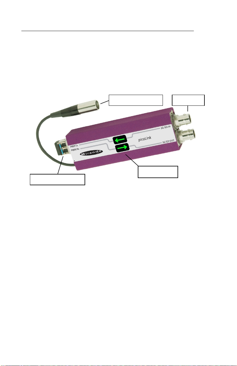
Fiber SFP module
Power connector
I/O BNCs
Status LEDs
1.3 Product Overview
Figure 1 illustrates the FIO-991p's major parts and their locations. The SFP
module is inserted into the socket on the end of the FIO-991p chassis, and
the fiber is plugged into the SFP module. The 3G/HD/SD digital video inputs
and outputs appear on BNC conne ctors at the opposite end of the chassis.
Input status and SFP module status are provided by the stat us LEDs.
Finally, the power source is connected to the lockable power connector.
Figure 1: Overall view of the FIO-991p
1.4 Product Variants
The FIO-991p is available in eight different versions, based on the I/O
configuration. They are distinguished by the model designation on the label.
Within each version, some variations in functionality may be available by
selecting the SFP module.
2 | FIO-991p
Page 7
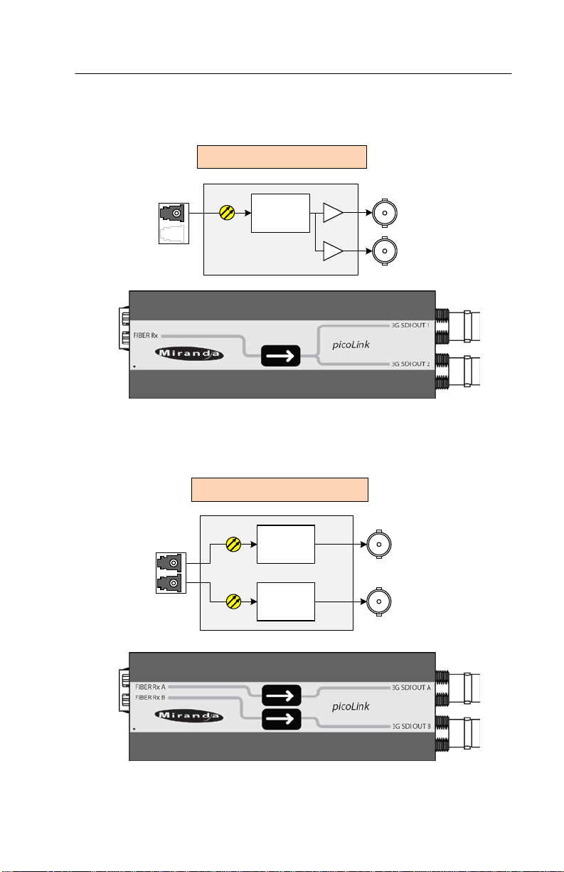
FIO-991p-RR-LC (Dual Rx)
FIO-991p-R-LC (Single Rx)
Optical
Rx
Optical
Rx
FIBER Rx A
FIBER Rx B
3G/HD/SD
SDI OUT A
3G/HD/SD
SDI OUT B
Optical
Rx
FIBER Rx
3G/HD/SD
SDI OUT 1
3G/HD/SD
SDI OUT 2
FIO-991p-R-LC
Single optical receiver, double 3G/HD/SD SDI output
FIO-991p-RR-LC
Dual optical receivers, dual 3G/HD/SD SDI outputs
GUIDE TO INSTALLATION AND OPERATION
FIO-991p | 3
Page 8

GUIDE TO INSTALLATION AND OPERATION
FIO-991p-T-S13-LC (Single Tx)
FIO-991p-RR-W-LC Dual Rx with WDM
Optical
Tx
3G/HD/SD
SDI IN
FIBER Tx
LOOP
Optical
Rx
Optical
Rx
FIBER Rx A,B
WDM
3G/HD/SD
SDI OUT A
3G/HD/SD
SDI OUT B
The WDM version receives two signals which are wave division multiplexed
onto a single fiber (one at 1310 nm and one at 1550 nm), and optically splits
them into the two receivers, each of which has an electrical output.
FIO-991p-T-LC
Single 3G/HD/SD SDI input with loop, single optical transmitter.
4 | FIO-991p
Page 9

FIO-991p-TT-S13S13-LC (Dual Tx)
FIO-991p-TT-W13W15-LC (Dual Tx with WDM)
FIBER Tx A,B
W
DM
3G/HD/SD
SDI
IN A
3G/HD/SD
SDI IN B
Optical
Tx
(1310 nm)
Optical
Tx
(1550 nm)
FIBER Tx A
FIBER Tx B
3G/HD/SD
SDI IN A
3G/HD/SD
SDI IN B
Optical
Tx
Optical
Tx
FIO-991p-TT-LC
Dual 3G/HD/SD SDI inputs, dual optical transmitters.
The WDM version has optical transmitters at 1310 nm and 1550 nm, to allow
the two signals to be wave-division multiplexed onto a single fiber.
GUIDE TO INSTALLATION AND OPERATION
FIO-991p | 5
Page 10

GUIDE TO INSTALLATION AND OPERATION
FIO-991p-TT-CXXCYY-LC (Dual Tx with CWDM)
FIO-991p-THTH-CXXCYY-LC (Dual High Power Tx with CWDM)
FIBER Tx A
FIBER Tx B
3G/HD/SD
SDI IN A
3G/HD/SD
SDI IN B
Optical
Tx
(1XX1 nm)
Optical
Tx
(1YY1 nm)
The CWDM version is designed to be used with an external optical
multiplexer, and is available with pairs of transmitters at the industrystandard frequencies for this application.
The XX and YY values in the product designation identify the wavelengths.
Note that the clasp handle on the SFP transmitter module is color-coded to
identify its operating wavelengths.
XX YY
27 29 1271 / 1291 nm Light Purple
31 33 1311 / 1331 nm Yellow Green
35 37 1351 / 1371 nm Pink
39 41 1391 / 1411 nm White
43 45 1431 / 1451 nm Black
47 49 1471 / 1491 nm Gray
51 53 1511 / 1531 nm Blue
55 57 1551 / 1571 nm
59 61 1591 / 1611 nm Red
Optical Signal
Wavelengths
Clasp Color Code
Yellow
6 | FIO-991p
Page 11

FIO-991p-RT-S13-LC (Rx & Tx)
FIO-991p-RT-W13-LC (Rx & Tx with WDM)
Optical
Tx
(1310 nm)
Optical
Rx
FIBER RxTx
W
DM
3G/HD/SD
SDI IN
3G/HD/SD
SDI OUT
Optical
Tx
Optical
Rx
FIBER Tx
FIBER Rx
3G/HD/SD
SDI OUT
3G/HD/SD
SDI IN
FIO-991p-RT-LC
Single 3G/HD/SD SDI input, single optical transmitter, plus
single optical receiver, single 3G/HD/SD SDI output.
WDM versions use a single fiber for input and output. The optical transmitter
can be selected to work at 1310 nm or 1550nm, w hile the optical receiver
functions at the other wavelength. The Tx wavelength is used to specify the
version (W13 for 1310 nm and W15 for 1550 nm).
GUIDE TO INSTALLATION AND OPERATION
FIO-991p | 7
Page 12

GUIDE TO INSTALLATION AND OPERATION
FIO-991p-RT-W15-LC (Rx & Tx with WDM)
FIO-991p-RD-S13-LC (O Repeater / E drop)
Optical
Tx
3G/HD/SD
SDI OUT 1
3G/HD/SD
SDI OUT 2
Optical
Rx
Optical
Tx
(1550 nm)
Optical
Rx
FIBER RxTx
WDM
3G/HD/SD
SDI IN
3G/HD/SD
SDI OUT
FIO-991p-RD-LC
Single optical receiver with double 3G/HD/SD SDI outputs, with the optical
input linked to a single optical transmitter. Functionally, an optical repeater
with electrical drop.
8 | FIO-991p
Page 13

GUIDE TO INSTALLATION AND OPERATION
FIO-991p-MADI-RT-M13-LC (multi-mo d e Rx & Tx)
FIO-991p-MADI-RT-S13-LC (single-mode Rx & Tx)
FIO-991p-MADI-RT-M13-LC
Single MADI input, single optical transmitter on multi-mode fiber, plus
single optical receiver, single MADI output.
FIO-991p-MADI-RT-S13-LC
Single MADI input, single optical transmitte r on single-mode fiber, plus
single optical receiver, single MADI output.
FIO-991p | 9
Page 14

GUIDE TO INSTALLATION AND OPERATION
Rear View
The back side of the unit shows the model type, serial number and other
details.
10 | FIO-991p
Page 15

GUIDE TO INSTALLATION AND OPERATION
2 Installation
2.1 Power Supply
The LKS-WSU power supply provides power to the FIO-991p for 110 V and
220 V operation. The power supply is a regulated +5 VDC@2.4 A power
source. The FIO-991p employs a mini XLR-3 connector for its power needs.
Figure 2 shows a detailed pinout of the male connector.
Figure 2: Power connector pinout
2.2 Power Adapter
The Pico-PA is a 12V-to-5V power adapter that can be used to
power the FIO-991p from a 12V battery supply in production
applications.
2.3 Installation in the pL Tray
The FIO-991p can be installed in Miranda’s pL Tray, a 1 RU frame with builtin power supply that can hold up to 10 picoLink devices.
The FIO-991p is installed with the BNC video connectors facing the front of
the tray, and the fiber optic and power supply connections on the back. See
the pL Tray manual for more details.
FIO-991p | 11
Page 16

GUIDE TO INSTALLATION AND OPERATION
2.4 Fiber Optic Interface
Installing and removing the Fiber I/O interface cartridge requires special
care.
The optical interface of the FIO-991p consists of two parts:
• A socket on one end of the chassis into which an SFP interface
module is plugged
• An SFP (Small Form-factor Pluggable) module into which the optical
fibers are plugged, and which incorporates the optical/electrical
interface
Cautions and Warnings
SFP Transmitter modules contain a class 1 laser, which emits
invisible radiation whenever the module is powered up. Because
the SFP is hot-swappable, the module may be powered up as soon
as it is installed.
DO NOT LOOK INTO AN OPERATING SFP MODULE’S
CONNECTORS, AS EYE DAMAGE MAY RESULT.
The SFP module is sensitive to electrostatic discharge (ESD). It is
recommended that you use a grounded ESD-preventive wrist strap
while handling the SFP module.
SFP modules are subject to wear, and their useful lifetime is
reduced each time they are inserted or removed. Do not remove
them more often than is absolutely necessary.
Never remove or install an SFP module with the fiber optic cables
connected. Damage to the cables could result.
The presence of dust and debris can seriously degrade the
performance of an optical interface. It is recommended that you
insert a dust plug into the SFP module whenever a fiber optic cable
is not connected.
12 | FIO-991p
Page 17

GUIDE TO INSTALLATION AND OPERATION
Installing an SFP module
1. Make sure that the bale clasp lever is in the
closed position
2. Position the SFP module so that the recessed slot is lined up with
the tab side of the socket.
3. Slide the module straight into the socket, and push gently until it
clicks into position.
Connecting the fiber optic cables
1. Remove the dust plug from the SFP module if present
2. Verify that the exposed end of the optical fiber in the LC connector
is clean
• Carefully remove any debris if necessary .
3. Plug the LC-terminated fiber optic cable into the SFP module
Removing the fiber optic cables
1. Grasp the LC fiber optic connector that is plugged into the SFP
module, and pull it straight out to disengage the optical fiber from
the SFP.
• Never pull the fiber optic cable itself, as catastrophi c dama ge
may occur.
2. Insert a dust plug into the SFP module.
Removing the SFP module
1. Move the bale clasp lever to the open
position.
2. Grasp the SFP module between your thumb and forefinger, and
pull it straight out of the slot.
FIO-991p | 13
Page 18

GUIDE TO INSTALLATION AND OPERATION
• Do NOT pull on the bale clasp lever to remove the module, as
it is easily damaged
• You may find that you need to wiggle the module, or perhaps
push it into the slot a bit, before it will release and slide out.
3. Insert a dust plug into the SFP module.
2.5 3G/HD/SD Digital Video and MADI Digital Audio Connections
The input and output electrical signals are connected via BNC connectors on
the end of the FIO-991p chassis. The connectors are labeled to identify
inputs and outputs.
The FIO-991p supports 3G, HD-SDI, SD-SDI, and DVB-ASI digital video
signals, and MADI digital audio signals. See the Specifications on page 16
for more details.
14 | FIO-991p
Page 19

GUIDE TO INSTALLATION AND OPERATION
3 Operation
There are no operating contr ols on the FIO-991p.
Configuration is automatic, depending on the model and the installed SFP
module.
3.1 Status LED assignments
The FIO-991p includes two arrow-shaped status LEDs, integrated into the
case’s graphics and labeled a ppropriately, which monitor the status of the
inputs. The arrow shows the direction of signal flow, and the color shows the
status of the associated input. The functionality of the LEDs varies with the
model type, as shown in this chart:
FIO-991p model LED 1 LED 2
TT Electrical In A Electrical In B
T Electrical In A
RR Optical In A Optical In B
R Optical In A
RT Electrical In A Optical In A
RD Optical In A
MADI-RT Electrical In A Optical In A
3.2 Status LED behavior
LEDs assigned to monitor Electrical Inputs dis play this beha v ior:
o Green = SDI signal OK
o Yellow = No lock
o Red = No signal
LEDs assigned to monitor Optical Inputs dis play this behavio r:
o Green = Optical signal OK
o Yellow = No lock
o Flashing Yellow = Input level too high or too low
o Red = No signal
In addition, LEDs in all models monitor the status of the installed SFP
module. The LEDs on any FIO-991p will flash red in the following cases:
o No SFP module
o SFP mismatch – wrong SFP type for the FIO-991p model
o Tx laser fault (SFP transmitter modules only – faulty channel LED will
flash)
FIO-991p | 15
Page 20

GUIDE TO INSTALLATION AND OPERATION
4 Specifications
ELECTRICAL
Signal: 3G/HD/SD SDI SMPTE 424M, 292M, and 259M-C
compliant
Supports data rates of 270, 1483.5, 1485, 2967,
2970 Mbps
EN50 83-9 DVB-ASI 270 Mbps
MADI-compliant, AES10-2008
Connectors: 75 ohm BNC (IEC 60169-8, Annex A)
Return Loss: Video >15 dB up to 1.5 GHz
>10 dB from 1.5 GHz to 3 GHz
MADI
COAXIAL INPUT
Cable length 3G: 100 m (325') @ 3Gbps
(Belden 1694A): HD: 150 m (500') @ 1.5 Gbps
SD: 350 m (1150') @ 270 Mbps
MADI: 100 m (325’)
Signal amplitude: MADI : 150 to 1200 mV p-p ; 4 V p-p tolerant
COAXIAL OUTPUT
Jitter (wideband): HD/SD: <0.2 UI
3Gbps: <0.3 UI
Rise / Fall time: 135 ps max., 20% to 80%, for HD
400-800 ps, 20% to 80%, for SD or non-reclocked
1-3 ns, 20% to 80%, for MADI
Signal amplitude: MADI: 550 ± 50 mV p-p
OPTICAL I/O
Video: SMPTE-297M-2006 compliant
MADI: ISO/IEC 9314-3 compliant (FDDI)
Connectors: LC
(note – these are not the connectors prescribd by
the FDDI and MADI standards)
16 | FIO-991p
Page 21

GUIDE TO INSTALLATION AND OPERATION
Rx CHANNEL (pathological bitstream)
Video
Sensitivity: 270 Mbps and 1.5 Gbps: -20 d B m
3Gbps: -18 dBm
MADI (single-mode) (multi-mode)
Sensitivity @ 1310 nm: -31 dBm -31 dBm
Maximum level: -8 dBm -14 dBm
Fiber length: 10 km (6.25 miles). 2 km (1.25 miles)
Tx CHANNEL (single-mode)
FIO-991-T-S13-LC: 1310 nm -5 dBm 0 dBm
FIO-991-TT-S13S13-LC: 1310 nm -5 dBm 0 dBm
FIO-991-RT-S13-LC: 1310 nm -7 dBm 0 dBm
FIO-991-TT-W13W15-LC: 1310 nm -5 dBm 0 dBm
1550 nm -8 dBm -3 dBm
FIO-991-TT-CXXCYY-LC: -6 dBm -3 dBm
FIO-991-THTH-CXXCYY-LC: 0 dBm 4 dBm
FIO-991p-MADI-RT-S13-LC 1310 nm -15 dBm -8 dBm
Tx CHANNEL (multi-mode)
FIO-991p-MADI-RT-M13-LC 1310 nm -20 dBm -14 dBm
PROCESSING PERFORMANCE
Signal path: 10 bits
Latency: <6 ns
ELECTRICAL
Voltage: 5 VDC
Power:
Wavelength Min Max
Wavelength Min Max
<
3 W
FIO-991p | 17
 Loading...