

Grandview GPCM-B User Manual
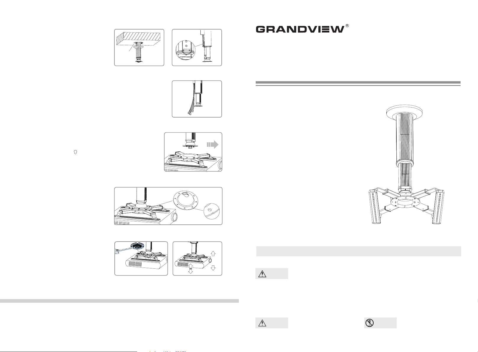
A. Please install GPC support bar
assembly on the ceiling
Fix the bas e o n the cei ling or con crete
1.
(pl ease e nsu re that th e lo ad is 40kg at l east).
Fig ure 7
2.
Ope n the b ack orna men t boa rd b, an d
lo osen the s crews of s ubsidia ry arm④
Ple ase adjust the subs idi ary arm④ t o y our
des ired positio n (t his fun ction is on ly f or
B20 0、 B30 0), and then faste n t he screws
again. Please hide the po wer line in to t he g ap
and clos e the b ack o rna ment boa rd ③ b .
Fig ure 9 and Figure 10.
B.
Please connect the GPC support bar
③
assembly and GPM projector fixation
Acc ordin g to fig ure 10 and figu re 11, plea se
1.
adj ust the g roove of ha lf- cycle junction to be
con siste nt with the dir ect ion of t he project or.
Th e pos iti oni ng ba r of G PC ha lf -cy cle
jun ction mus t be ali gn to the g roo ve o f GPC
pro jecto r fix ati on, and the n cir cum rot ate for
fas tenin g. Finally, conn ect GPC half -cycle
jun ction⑤
wit h two M4x 5 pre ssing scre ws.
Ple ase e nsure whe ther the GPC proje cto r
2.
fix ation i s fas tened.
Connecti on of p ower cord to p roj ector.
3.
4.
Install th e bac k ornament b oar d.
and GPC pr ojector f ixa tion u sin g
.
M6-M8 Expanding
Screw or Tapping
Screw
Figur e 7 Figur e 8
Figur e 9
Figur e 10
GRANDVIEW REPRODUCING GENUINE COLORS
Projector Lift GPCM-B
Appli cable Model:GPCM-B Se ries
Please read before using
Thank y ou for pur chasing our products.
Pl e ase re a d t h e i n st r uc t ion ma n ual
carefully i n orde r to ens ure this projector lift
is suitable f or your projection e quipment.
This projec tor lift must be installed for the
bottom of proj ector (bottom area: length is
280mm; widt h is 255mm).
(Figure: sui table area for pr ojector lift)
Instruction Manual
C. Adjust your desired angle.
Loose n t he screw s of GPC su pport ba r
1.
as sem bl y⑥
pro jecto r to your desired posi tio n and fasten
it. F igure 1 2
2. T he dir ect ion of pr ojector can be ad jus ted by
for ward 30° an d backward 3 °. Left a nd right
adj ustme nt is 3 °. Figure 13 .
vi a th e sp ann ed ; ad jus t t he
Grandview Crystal Screen Canada Ltd.
#11- 3751 N orth Fra ser Way,
Marin e Way Business Cen tre,
Burna by, BC, Cana da V5J 5G 4
Tel: 1-604-412-9 777 Fax: 1-604- 412-9796
Websi te: www.gr andvi ewscre en.ca
Figur e 11
3°
3°
Figur e 12 Figur e 13
30°
Guangzhou Grandview Crystal Screen Co., Ltd.
P.O. 511400 Fede ral Ind. Zone No. 3 63, Yushan We st Road ,
Shiqiao, Pan yu District, Gu angzhou, Guan gdong, China
Tel: +8620-8489- 9499 Fax: +8620 -8480-3343
Websi te: www.gr andvi ewscre en.co m
Cautious
Warnings
Caution
This in struction man ual is written fo r dealers and technicians.
The customer must employ the technicians for installation. Please process the
const ruction follo wing this instr uction manual to avoid injury caused by accidents.
For safety, the minimum load of ceiling must be 40KG
Pleas e do not incline the
proje ctor the extremely.
Do not
take apart
Pleas e do not take apart the
accessories of projector lift.

Diagram for applicable projector area
GPC
This projector lift must be installed on the bottom of projector (length 240mm;
width 255mm). Figure 1. Note: there is a spot of insatllation , figure 2.
5
5
2
280
Figure 1
10x30mm
spot of insa tllation
Figure 2
Components and Accessories
GPCM-B is combined by GPC and GPM .
Spe cific ati ons
Model
Adjust distance
for each grid
Specifications for
Multifunctional Arm
The length of
main arm ⑧
The length of
subsidiary arm ⑧a
Loa d
Optional Accessories( )Support Bar、Multifunctional Arm
Pro duct Na me
The le ngth of s uppor t bar
Spec ifica tion fo r Multi funct ional A rm
GPM
⑦
⑧ ⑧a
⑨
⑨a
①
②
③
③a
③b
④
④a
⑤
⑤a
⑤b
⑥
GPC
30mm
GPC M-B
/
Min 280mm
Max 360mm
H
30x 295
70
50
25k g
Max 360mm
Min 280mm
8mm
19
n
2
x
Mi
a
M
Top V iew
255mm
295mm
Bot tom Vie w
130mm
Fro nt View
Unit (mm)
16
Unit (mm)
Spe cific ation s
400 /600/ 800
30x 355
55mm
60mm
1. Assembly
The main bar and the subsidiary bar are fixed together from factory. And
the posit ioning bar is installed on half-cycle junction⑤ b. Before installation,
pleas e put the half-cycle junction⑤ on subsidiary bar④. Please put the glider ⑤
b on the half-cycle junction⑤, and then fasten the screw.
2. Adjustment
Loosen the screens of main bar③ and subsidiary bar④ . The distance between
proje ctor and ceiling can be adjusted according to the distance of install holes
betwe en main bar③ and subsidiary bar④ . Please refer to H in specification
table .
(Note: GPCM-B100 is no subsidiary bar and no stretch function).
③ ④
GPM
Usage
1. If need, please loosen the screws on the main arm⑧ and
subsi diary arm⑧a to exte nd the arms.
2. Please follow figure 4 or figure 5 to install the multifunctional
ar m, b ec au se of d iffe rent p roje ctor s. In ad diti on, th e
multi functional ar m can be invisibl e from the projector.
3. Put the main fixation⑦ on projector at the central gravity. Make
sure th e two holes on the main fixation⑦ locate at the both side.
4. Before connecting GPC main bar③, plea se fasten the screws
of main arm⑧ and subsidiary arm⑧a.
Figure 4 Figure 5 Figure 6
Figure 3
Parts :
① Base (1pc)
② Ornament Cover (1pc)
③ Main Bar (1pc)
③a Front Ornament Board
③b Back Or nament Board
④ Subsi diary Bar(1pc )
Acces sories
M4x10 P ressin g Screw (4 pcs)
M4x5 Pr essing S crew (2p cs)
M3x10 C ross Mac hine Scr ew(4pc s)
M4x10 C ross Mac hine Scr ew(4pc s)
M5x10 C ross Mac hine Scr ew(8pc s)
M5x30 C ross Mac hine Scr ew(4pc s)
④a Ornament board for
subsidiary bar
⑤ Half-Cycle Junction (1pc)
⑤a Posit ioning Screw (2pcs)
⑤b Glide r (1pc)
⑥ Main Screw (1pc)
M3x20 C ross Mac hine Scr ew(4pc s)
M4x20 C ross Mac hine Scr ew(4pc s)
M5x20 C ross Mac hine Scr ew(4pc s)
M3x30 C ross Mac hine Scr ew(4pc s)
M4x30 C ross Mac hine Scr ew(4pc s)
M6 Drop I n Anchor s(3 sets )
⑦ Main Fixation (1pc)
⑧ Main Arm (4pcs)
⑧a Subsi diary Arm (4pcs )
⑨ Multi functional Arm (2pcs)
⑨a Ornament board for
Multifunctional Arm(4pcs)
16x10 R ubber In sert(4 pcs)
16x20 R ubber In sert(2 pcs)
Washe r(4pcs )
Sprin g Washer
Spann er (1pc)
(4pcs )
Three steps for installation
A
A. Pl ease install GPC suppo rt
bar assembly on the ceiling
B. Pl ease connect the GPC
support bar assembly and
GPM projector fixation
B C
3°
C. Ad just your d esired angle.
3°
30°
 Loading...