

Page 1

Grandstream Networks, Inc.
GXP – 2000
SIP Enterprise Phone
GXP– 2000 User’s Manual www.grandstream.com
Firmware Version 1.1.1.14 support@grandstream.com
Page 2

TABLE OF CONTENTS
GXW- 2000 USER’S MANUAL
WELCOME....................................................................................................................................................4
INSTALLATION............................................................................................................................................5
EQUIPMENT PACKAGING ...............................................................................................................................5
CONNECTING YOUR PHONE ..........................................................................................................................5
WALL MOUNT ............................................................................................................................................... 6
GXP EXTENSION SIDE CAR ..........................................................................................................................6
SAFETY COMPLIANCES .................................................................................................................................7
WARRANTY ..................................................................................................................................................7
PRODUCT OVERVIEW ................................................................................................................................ 8
USING GXP-2000 SIP ENTERPRISE PHONE .......................................................................................... 10
GETTING FAMILIAR WITH LCD ..................................................................................................................... 10
COMPLETING AND ANSWERING PHONE CALLS.............................................................................................. 12
Handset, Speakerphone and Headset Mode........................................................................................12
Multiple SIP Accounts and Lines...........................................................................................................12
Completing Calls...................................................................................................................................12
Making Calls using IP Addresses..........................................................................................................13
Quick IP Call Mode................................................................................................................................13
Receiving Calls......................................................................................................................................13
Call Waiting/ Call Hold...........................................................................................................................13
Call Transfer..........................................................................................................................................13
3-Way Conferencing..............................................................................................................................14
Check Messages (Message Waiting Indicator).....................................................................................14
Mute/Delete...........................................................................................................................................14
Do Not Disturb.......................................................................................................................................14
Speed Dial.............................................................................................................................................14
Asterisk Busy Line Field........................................................................................................................14
Extension Board....................................................................................................................................15
CALL FEATURES ......................................................................................................................................... 15
CUSTOMIZED LCD SCREEN & XML ............................................................................................................. 15
CONFIGURATION GUIDE ..............................................................................................................................16
CONFIGURATION WITH KEYPAD.................................................................................................................16
CONFIGURATION WITH WEB BROWSER .....................................................................................................18
ACCESS THE WEB CONFIGURATION MENU................................................................................................18
END USER CONFIGURATION.....................................................................................................................18
ADVANCED USER CONFIGURATION ...........................................................................................................20
INDIVIDUAL ACCOUNT SETTINGS...............................................................................................................23
Saving the Configuration Changes .......................................................................................................26
Rebooting the Phone from Remote.......................................................................................................26
CONFIGURATION THROUGH SECURE CENTRAL PROVISIONING SERVER ......................................................... 26
SOFTWARE UPGRADE & CUSTOMIZATION..........................................................................................27
Firmware Upgrade through TFTP/HTTP.................................................................................................. 27
Key Pad Menu.......................................................................................................................................27
Web Configuration Interface .................................................................................................................27
No Local TFTP Server...........................................................................................................................27
CONFIGURATION FILE DOWNLOAD ...............................................................................................................28
Managing Firmware and Configuration File Download.........................................................................28
RESTORE FACTORY DEFAULT SETTING.............................................................................................. 29
GLOSSARY OF TERMS ............................................................................................................................ 30
Grandstream Networks, Inc. GXP-2000 Users Manual Page 2 of 33
Firmware 1.1.1.14 Last Updated: 12/2006
Page 3

TABLE OF FIGURES
GXW- 2000 USER’S MANUAL
FIGURE 1: CONNECTING THE GXP-2000 .........................................................................................................5
FIGURE 2: CONNECTING THE GXP-2000 AND THE GXP-EXTENSION ................................................................. 7
FIGURE 3: GXP-2000 INTERNAL HEADSET WIRING SCHEMA ............................................................................ 7
FIGURE 4: GETTING FAMILIAR WITH KEYPAD .................................................................................................. 11
TABLE OF TABLES
GXW- 2000 USER’S MANUAL
TABLE 1: DEFINITIONS OF THE GXP- 2000 CONNECTORS................................................................................. 5
TABLE 2: GXP KEY FEATURES IN A GLANCE .................................................................................................... 8
TABLE 3: HARDWARE SPECIFICATIONS ............................................................................................................ 8
TABLE 4: GXP-2000 TECHNICAL SPECIFICATIONS ........................................................................................... 9
TABLE 5: LCD ICON DEFINITIONS .................................................................................................................. 10
TABLE 7: GXP-2000 CALL FEATURES ...........................................................................................................15
TABLE 8: KEY PAD CONFIGURATION MENU .................................................................................................... 16
TABLE 9: DEVICE CONFIGURATION – BASIC SETTINGS DEFINITIONS ................................................................ 18
TABLE 10: DEVICE CONFIGURATION - STATUS DEFINITIONS ............................................................................ 19
TABLE 11: ADVANCED USER CONFIGURATION PAGE DEFINITIONS................................................................... 20
TABLE 12: SIP ACCOUNT CONFIGURATION PAGE DEFINITIONS ....................................................................... 23
GUI INTERFACE EXAMPLES
GXW- 2000 USER’S MANUAL
(download GUI Interfaces @
www.grandstream.com/downloads.html)
1. SCREENSHOT OF CONFIGURATION LOGIN PAGE
2. S
CREENSHOT OF BASIC SETTINGS CONFIGURATION PAGE
CREENSHOT OF STATUS CONFIGURATION PAGE
3. S
4. S
TATUS CONFIGURATION PAGE DEFINITIONS
5. S
CREENSHOT OF ADVANCED USER CONFIGURATION PAGE
6. SCREENSHOT OF SIP ACCOUNT CONFIGURATION
7. SCREENSHOT OF SAVED CONFIGURATION CHANGES
8. S
CREENSHOT OF REBOOT PAGE
Grandstream Networks, Inc. GXP-2000 Users Manual Page 3 of 33
Firmware 1.1.1.14 Last Updated: 12/2006
Page 4

Welcome
Thank you for purchasing the Grandstream GXP – 2000 SIP Enterprise Phone, an affordable, high-quality
IP phone designed for the small to large business enterprise.
Grandstream GXP-2000 is a next-generation enterprise SIP telephone that is feature rich, easy to use,
supports Power-over-Ethernet. The GXP-2000 is ideal for the small and medium size business seriously
looking to leverage their broadband network. Leading industry experts consistently recognize the GXP-
2000 as best in class. It recently received the prestigious 2006 “Excellence Award” from Internet
Telephony Magazine.
The GXP-2000 features intuitive user interfaces, four(4) individual lines, dual 10/100mbps Ethernet ports,
graphical LCD display and a secure central configuration. This SIP phone combines feature functionality
with the latest technology to offer excellent audio quality, ease of use, expandability, and broad
interoperability with 3
Caution: Changes or modifications to this product not expressly approved by Grandstream, or operation
of this product in any way other than as detailed by this User Manual, could void your manufacturer
warranty.
• This document is contains links to Grandstream GUI Interfaces. Please download these examples
http://www.grandstream.com/GUI Interfaces/GXP-2000 for your reference.
• This document is subject to change without notice. The latest electronic version of this user manual
is available for download @:
• Reproduction or transmittal of the entire or any part, in any form or by any m eans, electronic or print,
for any purpose without the express written permission of Grandstream Networks, Inc. is not
permitted.
rd
party SIP platforms. It is ideal for any business communication environment.
http://www.grandstream.com/user_manuals/GXP-2000.pdf
Grandstream Networks, Inc. GXP-2000 Users Manual Page 4 of 33
Firmware 1.1.1.14 Last Updated: 12/2006
Page 5

Installation
.
EQUIPMENT PACKAGING
The GXP-2000 phone package contains:
1) One GXP-2000 Main Case
2)
One Handset
3) One Phone Co
4) One Universal Pow
5)
One Ethernet Cable
he GX tains:
T P-Extension package con
One GXP-Extension unit
6)
7) One PS2 cable
8) One connection plate
9) One Universal Power Ada
CONNE TING YOUR PHONE
C
Figure 1: Connecting the GXP-2000
rd
er Adaptor
ptor
GXP Ext
Connection
Table 1: Definitions of th
GXP
Ext Connection
WAN/LAN
Connect the GXP Ext directly to the GXP using connection e. Draws power cabl
from PoE.
10/100Mbps RJ-45 ports for WAN (PC) and LAN connections (switched or routed)
Support PoE (802.3af). Draws power from both spare line and signal line
WAN/LAN RJ-45
10/100Mbps ports
e GXP- 2000 Connectors
Power
Jack
Headset Jet
Power Jack
Headset Jack
Grandstream Networks, Inc. GXP-2000 Users Manual Page 5 of 33
Firmware 1.1.1.14 Last Updated: 12/2006
5V DC power port; UL Certified
2.5mm Headset port
Page 6

WA
LL MOUNT
P-2000 can be w
GX all m one on the wall, place two fixed hangers on the wall,
h
ang the back of the phone on the fixed hangers.
ounted. To position the ph
Top Wall
Mount hole
Bottom Wall
Mount hole
To use the handset, pull out the tab (extension downward) fr
om the handset cradle, rotate the tab and plug it
back into the slot with the extension up to hold the handset.
Tab with
Handset
Rest
extension
Tab with
extension up
EXTENSION SIDE CAR
GXP
GXP-2000 supports two (2) extension side cars, providing up to 112
Each GXP Extensio
mp fie e
ld) and BLA (bridg d line appearance). Connect the first GXP -EXT to the GXP-2000 using the
la
PS2 cable found in the GXP Ext packag
n has 56 multi-purpose keys, dual color LEDs (red/green) and support BLF (busy
e. The first GXP-Ext draws power directly from the phone.
additional programmable extensions.
Connect the second GXP Ext using the connection plate and the PS2 cable. The GXP2000 will
automatically reboot and power up the GXP Extensions. Grandstream recommends, though not requi
to use a separate power supply with the second GXP Ext. NOTE: should your system loose power,
please unplug your devices and power up the GXP-2000 first.
Powering up the system:
red,
1. The GXP-2000 will boot up first;
2. The GXP LEDs will be solid red;
3. The status light in t
4. All of the LED indic
he top right corner of the GXP-Ext will blink red;
ators on the GXP-Ext will flash three times;
5. The status light at the top right cor
Grandstream Networks, Inc. GXP-2000 Users Manual Page 6 of 33
Firmware 1.1.1.14 Last Updated: 12/2006
ner of the GXP-Ext will turn to solid green.
Page 7
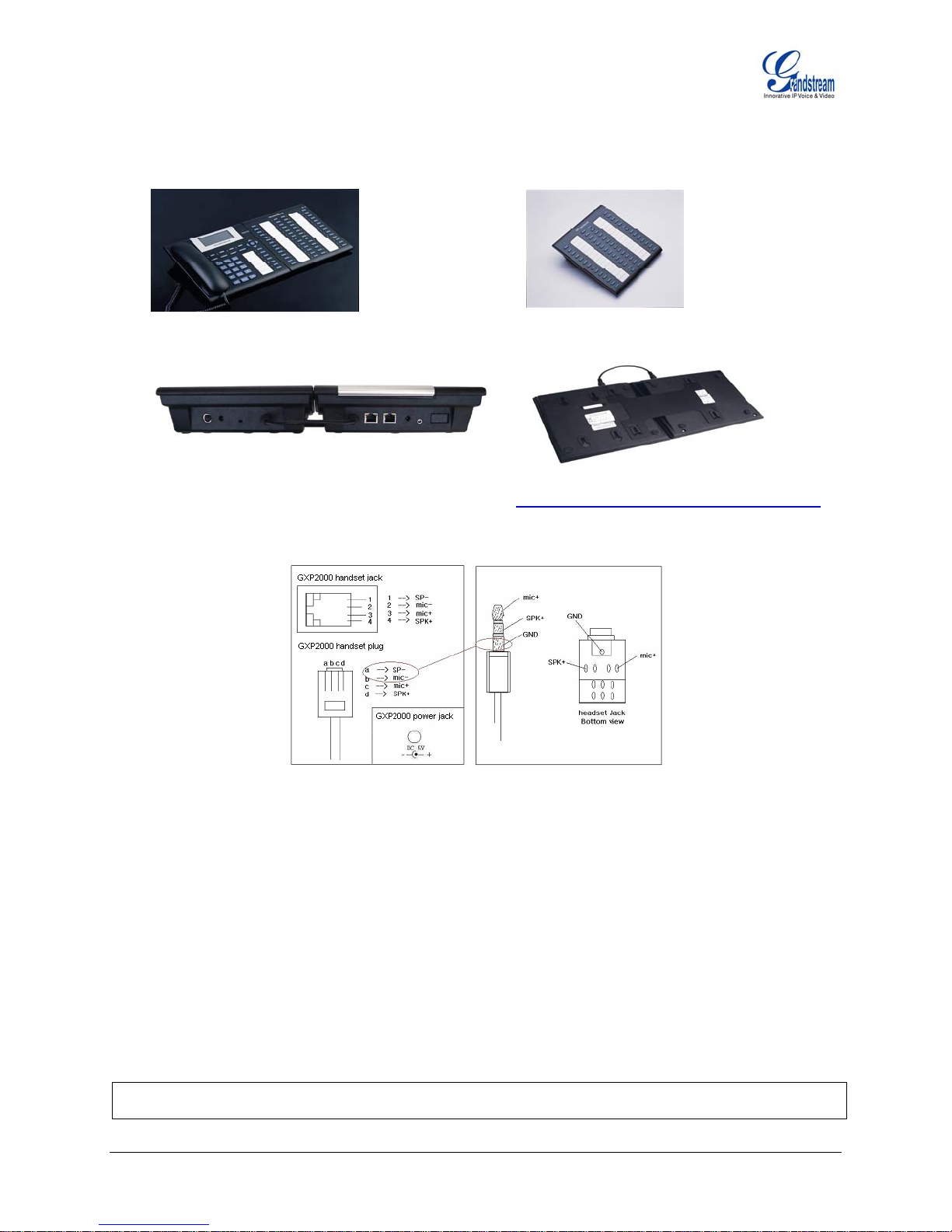
Figure 2: Connecting the GXP-2000 and the GXP-Extension
GXP-2000 w/GXP-Extension GXP
Extension
e
Connecting the GXP-2000
w/GXP-Extension
Reverse side of conn ction
w/connection plate
N
OTE: Ensure your GXP-2000 has the latest firmware at http://www.grandstream.com/y-firmware.htm
IGURE 3: GXP-2000 INTERNAL HEADSET WIRING SCHEMA F
.
N
OTE: A 3.5mm to 2.5mm plug converter is required to use a 2.5mm headset. Purchase a converter at
any electronics store.
AFETY COMPLIANCES S
The GXP-2000 phone
adaptor is compliant with UL standard. Only use the universal power adapter provided with the GXP
package. The manufacturer’s warranty does not cover damages to the phone caused by unsupported
complies with FCC/CE and various safety standards. The GXP-2000 power
power adaptors.
ARRANTY W
If you purcha
phone for replacement, repair or refund. If you purchased the product directly from Grandstream, co
sed your GXP from a reseller, please contact the company where you purchased your
ntact
your Grandstream Sales and Service Representative for a RMA (Return Materials Authorization) number
before you return the product. Grandstream reserves the right to remedy warranty policy without prior
notification.
Warning:
Please do not use a different power adaptor with the GXP-2000 or the GXP-Extension as
they may cause damage to the products and void the manufacturer warranty.
Grandstream Networks, Inc. GXP-2000 Users Manual Page 7 of 33
Firmware 1.1.1.14 Last Updated: 12/2006
Page 8

P
roduct Overview
Back View Desk View Side View
Table 2: GXP Key Features in a Glance
Feature Benefit
Open Standards Compatible
SIP 2.0, TCP/IP/UDP, RTP/RTCP, HTTP/HTTPS, ARP/RARP, ICMP,
DNS (A record and SRV), DHCP (both client and server), PPPoE,
TFTP, NTP, Telnet, and TLS.
Network Interfaces
Dual 10/100mbps Ethernet ports; 2 USB (2.0) host ports, headset
jack.
Superb Audio Quality
Advanced Digital Signal Processing (DSP), Silence suppression,
VAD, CNG, AGC.
Feature Rich
Standard voice features including caller ID, call waiting, hold, transfer,
forward, block, mute, autodial, off-hook dial, and click to dial.
Advanced Functionality
Multi-line support, multi-party conferencing, up to 112 additional
extensions, headset enabled, intercom, AES encryption.
Advanced Features
Custom down-loadable ring-tones, Multi-language support (MLS),
XML enabled, SRTP & TLS (pending)
Table 3: Hardware Specifications
Feature / Model GXP- 2000
LAN Interface (Ethernet ports)
Graphic LCD Display
Expansion Module Support
Headset Jack
LED
Power over Ethernet
Two (2) 10/100 Full/Half Duplex Ethernet Switch with LAN and PC port
with auto detection
8 line x 22 character; 64 rows x 131 columns in pixels
Yes
2.5mm Headset port
11 LED with different light pattern in dual color (g/r)
Built-in, autosensing: Cisco and IEEE 802.3af standard: can
draw power from both spare lines or signal lines from Ethernet
Universal Switching
Power Adaptor
Dimension
Weight
Temperature
Humidity
Compliance
Input: 100-240VAC 50-60 Hz
Output: +5VDC, 1200mA, UL certified
220mm(l) x 215mm(w) x 57mm(h)
0.82kg (1.8lbs)
32–104
10% - 90% (non-condensing)
FCC / CE / C-Tick
o
F/ 0–40oC
Grandstream Networks, Inc. GXP-2000 Users Manual Page 8 of 33
Firmware 1.1.1.14 Last Updated: 12/2006
Page 9

Table 4: GXP-2000 Techni
Lines
4 direct lines
with 2 -2000 Ext)
Protocol
Support
Support SIP 2.0, TCP/UDP/IP, PPPoE, RTP/RTCP, SRTP by SDES, HTTP,
ARP/RARP, ICMP, DNS, DHCP, NTP/SNTP, TFTP, SIMPLE/PRESENCE protocols
Support multiple SIP accounts and up to 11 media channels concurrently
Support SIP PUBLISH method (RFC 3903), SIP Presence package (RFC 3856,
3863) for use of 7 MFKs and GXP-2000EXT, SIP Dialog package (RFC 4235)
Support for SIP MESSAGE method (RFC 3428)S
Stores up to 100 incoming IM messages (drops IM message 101 plus)
Display
Feature Keys
8 line x 22c rows x 130 column in pixels
8 dedicated keys: Me
Send, Mute/Del, 5 disp
Device
Management
NAT-friend
including b
Address Book
Audio Features
Suppo
Suppo
200 n console
0 Extensio
Full-duplex ha one, headset enabled
Advanced Dig
Dynamic nego
Suppo
G.728, G.722
-band and o
In
Silence Suppr NG (comfort noise
generation), ANG (automatic gain control)
Acoustic Echo C
speakerphone m
Support side
loss conceal
itive graphic u ML, LDAP), MLS
Te
lephony
Fe
atures
Intu
(mu
lti lan
Voice ma
Call hold, call tra
ot-Disturb (D
Do-N
l, call log, an
redia
Transfer, hold, fo to
er, early dia onymous call using privacy header
answ l and speed dial. Support for an
Ne
twork and
Pr
ovisioning
Fi
rmware
Up
grades
anced
Adv
er Features
Serv
Security
Via kepad/LCD, W ) central configuration file,
manual or dynam ) network setup
Support NAT trav STUN and Symmetric RTP
Support for IEEE LAN), Layer 3 TOS
Support firmware upport for Authenticating
configuration file ges
User specific URL for configuration file and firmware files
Message waiting indication, support DNS SRV Look up and SIP Server Fail Over,
Support customizable idle screen via downloading XML by HTTP/TFTP
DIGEST authentication and encryption using MD5 and MD5-sess, SRTP over TLS
cal Specifications
with 7 speed dial keys; up to 11 line calls (with an additional 112 lines
daisy-chained GXP
haracter, 64
ssage Button, Hold, Transfer, Conference, Speakerphone,
lay/menu navigation keys, dual color LEDs
emote software upgrade (via TFTP/HTTP) for deployed devices
ly r
d firewall/NAT, Auto/manual provisioning system, GUI Interface,
ehin
rt Layer
2 (802.1Q, VLAN, 802.1p) and Layer 3 QoS (ToS, DiffServ, MPLS)
rt for GXP-2000 Extension console and diagnostic mode for keys on GXP-
nds-free speakerph
ital Signal Processing (DSP)
tiation of codec and voice payload length
rt for G.
723,1 (6.3K), G.729A/B, G.711 µ/A, G.726 (40K/32K/24K/16K),
(wide-band), GSM and iLBC codecs
ut-of-band DTMF (in audio, RFC2833, SIP INFO)
ession, VAD (voice activity detection), C
ancellation (AEC) with Acoustic Gain Control (AGC) for
o
de
tone
, Adaptive jitter buffer control (patent-pending) and packet delay &
men
t
ser interface (GUI), downloadable phone book (X
guage s
il indica loadable custom ring-tones
upport)
tor with indicator, down
nsfer (attended/blind)
ND), call forwarding, call waiting, call waiting caller ID, mute,
d volume control, caller ID display or block
rward, multi-party conferencing, dial plans, off-hook auto dial, au
eb browser, or secure (AES encrypted
ic host configuration protocol (DHCP
ersal using IETF
802.1p/Q tagging (V
upgrade via TFTP or HTTP, S
before accepting chan
Grandstream Networks, Inc. GXP-2000 Users Manual Page 9 of 33
Firmware 1.1.1.14 Last Updated: 12/2006
Page 10
Using GXP-2000 SIP Enterprise Phone
GETTING WITH LCD
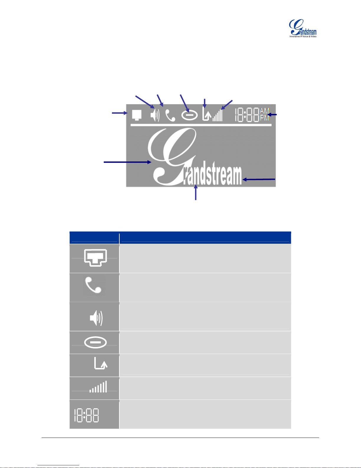
Table 5: LCD Icon
FAMILIAR
Connectiv
and/
SIP Proxy/Se
er ID:
UsDawill show
te
Name
Extension
Speaker -phone
enabled
ity Status
or
rver status
Definitions
Icon LCD Icon Definitions
Handset
enabled
Do Not
Disturb
(blinks)
(located here after boot-up)
Calls
Forwarded
Phone IP Address
Volume
Time
Use any
picture or logo
AM
PM
Connectivity Status / SIP Proxy/Server Icon:
Solid – connected to SIP Server/IP address received
Blinking – physical connection failed
Blank – SIP Proxy/Server not registered
Phone Status Icon:
OFF when the handset is on-hook
ON when the handset is off-hook
Speaker Phone Status Icon:
FLASH when phone rings or a call is pending
OFF when the speakerphone is off
ON when the speakerphone is on
DND Icon:
ON when the “do not disturb” is activated
Activate by pressing MUTE/DEL button twice
Calls Forwarded Icon:
INDICATES calls are forwarded
Follow ‘call forwarding’ procedures
Handset, Speakerphone and Ring Volume Icon:
Each icon appears next to the volume icon
To adjust volume, use the up/down button
Real-time Clock:
Synchronized to Internet time server
Time zone configurable via web browser
AM/PM indicator
Grandstream Networks, Inc. GXP-2000 Users Manual Page 10 of 33
Firmware 1.1.1.14 Last Updated: 12/2006
Page 11

Figure 4: Getting Familiar with Keypad
Adjustable LCD screen
Message Waiting Indicator
Line 1-4 Keys
Menu Keys
Mute/Delete
Message
Conference
Transfer
Speed Dial / Configurable
line indicators
Hold Speaker Send/Re-Dial Stand ard Keypad RJ11
Table 6: GXP Button Definitions
Key Button Key Button Definitions
LINE1-LINE4
UP ↑
DOWN ↓
LEFT Å
RIGHT Æ
OK
TRNF
CONF
4 Line keys with LED, can be configured to different SIP profiles
Use button to select next “Menu Item” when phone is in keypad configuration
mode; Or increase handset/speakerphone volume when phone is ACTIVE; Or
increase ring volume when phone is in IDLE mode
U is in keypad configure se button to select previous “Menu Item” when phone
m e when phone is ACTIVE; ode; Or decrease handset/speakerphone volum
O ode r decrease ring volume when is in IDLE m
Shift cursor to left
Shift cursor to right
Enter Keypad Configuration “MENU” mode when phone is in IDLE mode. Use
as ENTER key when in Keypad Configuration.
TRA l to another number NSFER key: Transfer an ACTIVE cal
Press CONF button to connect Calling/Called party into conference
MSG
SPEAKER
HOLD
SEND
0 - 9, *, #
Grandstream Networks, Inc. GXP-2000 Users Manual Page 11 of 33
Firmware 1.1.1.14 Last Updated: 12/2006
Ente es r to retrieve (video) voice mails or other messag
Enable/Disable hands-free speaker mode
Place ACTIVE call on hold
Press SEND to dial a new number or redial the last number dialed. Press
send ey entry timeout” value button to send a call immediately before “no k
expires
Standard phone keypad; press # key to send call; press * key to for IVR
functions
Page 12

COMPLETING AND ANSWERING PHONE CALLS
Handset, Speakerphone and Headset Mode
Handset can be toggled between Speaker or Headset. To switch between Handset and
Speaker/Headset, press the Hook Flash in the handset cradle or press the SPEAKER button.
Multiple SIP Accounts and Lines
The GXP-2000 can support up to 4 independent SIP accounts. Each account is capable of independent
SIP server, user and NAT settings. Each of the 4 line buttons (LINE1-LINE4) is “virtually” mapped to an
individual SIP account. In off-hook state, select an idle line and the name of the account (as configured in
the web interface) is displayed on the LCD and a dial tone is heard.
For example: Configure the 4 SIP accounts as “FreeWorldDialup”, “BroadVoice” , “FreeWorldDialup” and
“Asterisk PBX” respectively and ensure each is active and registered. When LINE1 is pressed, you will
hear a dial tone and see “FreeWorldDialup” on the LCD display; when LINE2 is pressed, you will hear a
dial tone and see “BroadVoice” on the LCD display; when LINE3 is pressed, you will hear a dial tone and
see “Asterisk PBX” on the LCD display.
To make a call, select the line you wish to use. The LED will light up solid red. Switch lines before dialing
b
y pressing the same LINE button one or more times. If you continue to press one LINE, the selected
a
ccount will circulate among the registered accounts.
For example: when LINE1 is pressed, the LCD displays “FreeWorldDialup”; If LINE1 is pressed twice, the
LCD displays “BroadVoice” and th made through SIP account 2 - BroadVoice.
oming calls to nt will attempt to use its corresponding LINE if it is not in us
Inc a specific accou e. When
the “virtually” mapped line is in use, the GXP-2000 will flash the next available LINE (from left to right) in
red.
A line is ACTIVE when it is in use
Completing Calls
There are four ways to complete
1. DIAL
Take Handset/SPEAKER/Headset off-hook or press an available LINE key (activates
:
speakerp
wish, sele
hone). The line e and the primary line (LINE1) LED is red. If you
ct another LINE key (altern nt). Enter the phone number and press the
SEND key.
EDIAL: Take Handset/SPEAKER/Headset off-hook or press an available LINE key (activates
2. R
sp sponding LED will be red. Press the SEND button to
eakerphone), the corre the last
numbe
r called.
3. U
SE THE MENU: Press the History and then
R
eceived Calls/Missed Cal ct and
press he call will dial out in speaker-mode
OK again to dial. T urrently applies only to primary
SIP account (LINE 1)).
AGING/INTERCOM: This is only valid if the SERVER/PBX supports this feature and both the
4. P
phon
e and PBX (e.g. As et
off
-hook, select the LINE
PAGE USING. Dial the p mber you want to Page/Intercom and press SEND key.
TE: Dial-
NO tone and dialed num
selected. The phone waits 4 seco y entry timeout) before sending and initiating the
call. Press the “SEND” button to override the 4 second delay.
e subsequent call will be
and the corresponding LED is solid red.
a call:
will have a dial ton
ative SIP accou
redial
OK button to bring up the Main Menu. Select Call
ls/Dialed Calls and select phone number. Press OK to sele
. (C
terisk) are correctly configured. Take the Handset/SPEAKER/Heads
key associated with account, press OK key to display LCD: LINEx:
hone nu
ber display occurs after the handset is off-hook and the line key is
nds (by default; no ke
Grandstream Networks, Inc. GXP-2000 Users Manual Page 12 of 33
Firmware 1.1.1.14 Last Updated: 12/2006
Page 13

Making Calls using IP Addresses
Direct IP calling allows two phones to talk to each other in an ad hoc fashion without a SIP proxy. VoIP
calls can be made between two phones if:
both phones have public IP addresses, or
•
• both phones are on a same LAN/VPN u
both phones can be connected through a router using public or private IP addresses (with
•
sing private or public IP addresses, or
necessary port forwarding or DMZ)
To make a direct IP call, press OK button to bring up MAIN MENU. Select “Direct IP Call”. Press OK to
select. Input the 12-digit target IP address. Press OK key to initiate ca
ll.
For example: If the target IP address is 192.168.1.60 and the port is 5062 (e.g. 192.168.1.60:5062), input
the following:
192*168*1*60#5062 - “ * ” key represent “.” and “#” key represent “:”. Press OK to dial ou
t.
Quick IP Call Mode
Dial an IP address under the same LAN/V
PN by keying in the last octet in the IP address. This simulates
a PBX function using the CMSA/CD without a SIP server. Controlled static IP usage is recommended.
In the “Advanced Settings” page, set the "Use Quick IP-call mode to YES. When #xxx is dialed, where
is 0-9 and xxx <=255, a direct IP call to aaa.bbb.ccc.XX
a
ddress regardless of subnet mask. The numbers #xx or #x are also valid. The leading 0 is not required
X is completed. “aaa.bbb.ccc” is from the local IP
(but OK).
For example:
192.168.0.2 calling 192.168.0.3 -- dial #3 follow by SEND or #
192.168.0.2 calling 192.168.0.23 -- dial #23 follow by SEND or #
192.168.0.2 calling 192.168.0.123 -- dial #123 follow by SEND or #
192.168.0.2: dial #3 and #03 and #003 results in the same call -- call 192.168.0.3
NIPOTE: If you have a SIP Server configured, a Direct IP-IP still works. If you
-IP call will also u
se STUN. Configure the “Use Random Port” to “NO” when completing Direct IP calls.
are using STUN, the Direct
eceiving Calls
R
1. Incoming single call
: Phone rings with selected ring-tone. The corresponding account LINE
flashes red. Answer call by taking Handset/SPEAKER/Headset off hook or pressing SPEAKER.
2.
Incoming multiple calls
red (as descri
bed in section 4.3.2).
3. Paging/Intercom Enabled
: Call Waiting tone (stutter tone) audible. Next available lines will flash
: Phone beeps once and automatically establishes the call via
SPEAKER. (PBX (or Server) must also supports this feature)
Call Waiting/ Call Hold
1. Hold: Place a call on ‘hold’ by pressing the “HOLD” button.
2.
3.
Call Tra
GXP-20
Resume:
Multiple Calls
to place or receive another call. Call Wa
nsfer
00 supports both
Resume call by pressing the corresponding blinking LINE.
: Automatically place ACTIVE call on ‘HOLD’ by selecting another available LINE
iting tone (stutter tone) audible when line is in use.
blind and attended (or supervised) transfer:
1. Blind Transfer: Press “TRNF” button, then dial the number and press the “SEND” button to
complete transfer of active call.
x
Grandstream Networks, Inc. GXP-2000 Users Manual Page 13 of 33
Firmware 1.1.1.14 Last Updated: 12/2006
Page 14

2. Attended (or Supervised) Transfer: Press “Linex” button to make a call and automatically
place the ACTIVE LINE on HOLD. Once the call is established, press “TRNF” key to transfer the
call and hang up.
N
OTE: To transfer calls across SIP domains, SIP service providers must support transfer across SIP
domains account SIP profile.
. Blind transfer will usually use the
primary
3-Way C
onferencing
GXP-2000 supports 3-way conferencing.
1. Initiate a Conference Call
: Place first call(er) on HOLD, call second party. Press the CONF
button then the LINE that is on HOLD (blinking). Repeat for third party.
2. Cancel Conference: If after pressing the “CONF” button, a user decides not to conference
anyone, press CONF again or the original LINE button. This will resume two-way conversation.
3. End Confere
nce: To end a conference, press HOLD. This breaks the conference and places
both parties on hold. To speak with an individual party, select the corresponding blinking LINE.
Check Messages (Message Waiting Indicator)
The blinking red MWI (Message Waiting Indicator) indicates a message is waiting. Press the MSG button
to retrieve the message. An IVR will prompt the user through the process of message retrieval. Press a
specific LINE to retrieve messages for a specific line account.
NOTE:
• Each lin cemail portal number to
be confi
• To chec ecks
the prim menu.
e has a separate voicemail account. Each account requires a voi
gured in the “voicemail user id” field.
k which line account has a message – 1) press the message button (this always ch
ary account), 2) check each line for stutter tone or 3) check missed calls using the
Mute/Delete
1. To enable/disable mute during a call, press “MUTE/DEL” button. The red Mute/Delete icon
(muted microphone) will flash on the LCD. Press the “MUTE/DEL” button to resume audio.
2. To delete
entries while using the “MAIN MENU” place cursor (use the arrows to move cursor)
before the entry. Press “MUTE/DEL” to delete the digit.
Not Disturb
Do
Press the “Mute/Delete” button if you
1. do not want to take a call. This will send the caller directly
to voicemail.
Press the “Mute/Delete” button to set phone to ‘do not disturb’ (icon will be o
2. n the screen). The
phone will not ring and send caller directly to voicemail. (see note above)
ed Dial
Spe
seven multi-functional buttons can be configured for speed dial. Press the
The speed dial button to
matically call the assigned extension.
auto
Not
LED will flash i d
functions keys s
first multi-functional button is in use, you cannot use it for speed dial/B
A
The
account on one of the multi-functional buttons, the Speed Dial function
he multi-functional buttons will function as LINE keys when all four primary lines are busy. Th
e: T e
n icating the incoming call. Press the button to pick up the call. If any one of the 7
i associated with a call, the speed dial/BLF function will not work. For example: when
LF.
sterisk Busy Line Field
seven multi-functional buttons can be configured for Asterisk Busy Line Field function with a specified
. When Asterisk BLF is configured
will work when it that line is not in use.
Grandstream Networks, Inc. GXP-2000 Users Manual Page 14 of 33
Firmware 1.1.1.14 Last Updated: 12/2006
Page 15

Extensi
The fifty n GXP-Extension board function the same as multi-functional
on Board
-six multi-functional buttons o
buttons on the phone base station. These extensions are fully programmable but can not be used as li
keys.
CALL FEATURES
The GXP-2000 supports traditional and ad
Tab
le 7: GXP-2000 Call Features
Key Call Features
*30
*31
*67
*82
*70
*71
Block Caller ID (for all subsequent calls)
Send Caller ID (for all subsequent calls)
Block Caller ID (per call)
Send Caller ID (per call)
Disable Call Waiting (per Call)
Enable Call Waiting (per Call)
*72 Unconditional Call Forward
Dial “*72” for a dial tone. Dial the forwarding number followed by “#”. Wait
for dial tone. LCD will display “Call FWD Activated”.
*73
Cancel Unconditional Call Forward: dial “*73” and get the dial tone, then
hang up. LCD will display “Call FWD Activated”.
*90 Busy Call Forward
Dial “*90” for a dial tone. Dial the forwarding number followed by “#”. Wait
for a dial tone. Hang up.
*91
Cancel Busy Call Forward: dial “*91”. Wait for dial tone. Hang up.
*92 Delayed Call Forward
Dial “*92” for a dial tone. Dial the forwarding number followed by “#”. Wait
for a dial tone. Hang up. LCD will display “Call FWD Activated”.
*93 Cancel Delayed Call Forward
Dial “*93” for a dial tone, then hang up.
USTOMIZED LCD SCREEN & XML
C
The GXP-2000 su
rmation and configuration guides are located on the website @
info
pports both a customized LCD idle-screen and a downloadable XML phonebook. Detailed
downloads.htm.
vanced telephony features.
http://www.grandstream.com/y-
ne
Grandstream Networks, Inc. GXP-2000 Users Manual Page 15 of 33
Firmware 1.1.1.14 Last Updated: 12/2006
Page 16

CONFIGURATION
CONFIGURATION WIT
GUIDE
H KEYPAD
To enter the MENU, press the round button. Navigate the menu by using the arrow keys: up/down and
left/right. Press the OK button to confirm a menu selection, delete an entry by pressing the MUTE/DEL button.
T
he phon
ft idle for 20 seconds.
le
Table 8: Key Pad C
isplay “Call History” Press Menu button to enter this menu inD
e automatically exits MENU mode with an incoming call, the phone is off-hook or the MENU mode if
onfiguration Menu
cluding
“Received Calls” or
“Dialed Calls” or
“Missed Calls” or
“Back”
lection Press ‘↓’ or ’↑’ to toggle the se
Press ‘←’ to return to the main menu
s” Display “Statu
o enter this menu to see the status of the phone Press Menu button t
gle the selection Press ‘↓’ or ’↑’ to tog
utton to exit Press Menu or ‘←’b
Display “Phone Book” Press Menu button to display the phone book including
“Download Phonebook”
Press ‘↓’ or ’↑’ to toggle the selection
nu item Press Menu button to choose the me
Press ‘←’ button to return to the main menu
Display ant Mes ed. “Inst sages” Press Menu button to display the Instant Messages receiv
Press ‘↓’ or ’↑’ to toggle the selection
Press Menu button to choose the menu item
Press ‘←’ button to return to the main menu
Note: GXP-2000 on
ly supports the function of receiving of Instant
Messages.
isplay “Direct IP Call” Press Menu button to display the direct IP call interface D
Enter the 12 digit IP address. For example, enter the IP address:
10.10.1.2 like
010010001002.
Press ‘←’ or ‘→’ to move the cursor or toggle the selection
Press Menu button to confirm.
Display “Preference” Press Menu button to enter this sub menu including
“Do NOT Disturb” or
“Ring Tone” or
“Ring Volume” or
“Download SCR XML” or
“Erase Custom SCR” or
“Back”
DND (Do NOT Disturb) function could be turned on or off in the “DO NOT
Disturb” menu.
Choose different ring tones in the “Ring Tone” menu.
Press ‘←’ or ‘→’ to adjust ring volume in the “Ring Volume” menu.
Press ‘↓’ or ’↑’ to toggle the selection.
Press Menu button to choose the menu item.
Press ‘←’ to return to the main menu.
Grandstream Networks, Inc. GXP-2000 Users Manual Page 16 of 33
Firmware 1.1.1.14 Last Updated: 12/2006
Page 17

Display “Configure” Press Menu button to display the configuration selections:
“Network” or
“SIP” or
“Audio” or
“Upgrade” or
“Factory Reset”
More detailed information on these selections are in the web
configuration page.
Press ‘↓’ or ’↑’ to toggle the selection.
Press ‘←’ to return the main menu.
Display “Factory Functions” display the factory function items including Press Menu to
“Ethernet Loopback” or
“Audio Loopback” or
“Diagnostic Mode” or
“Enable Diag Port” or
“Back”
Press ‘↓’ or ’↑’ to toggle between selections.
Press ‘←’ to return to the main menu.
Display “Reboot” device Press Menu button to reboot the
Display “Exit”
Press Menu button to exit the menu
Display “Ring Volume” Pres press ‘←’ or ’ →’ to s Menu button to hear the selected ring volume,
hear and adjust the ring tone volume.
Press Menu button to select and exit, take effect immediately.
Display “Ethernet Loopback” Press Menu button to enter this mode
Connect a cross Ethernet cable from your “PC” port, and the “LAN” port.
The test result is displayed on the screen. Use this feature to diagn
the state of h
ealth of the RJ45 jacks.
ose
Press Menu button to exit the diagnostic mode.
Display “Audio Loopback” Press Menu button to enter this mode
Speak into the handset. If you hear your voice in the handset, your audio
Press Menu button to exit the mode.
Display “Diagnostic Mode” nter this mode, all LEDs will light up Press Menu button to e
Press any key on the keypad, to display the button name in the LCD. Lift
Display “Factory Reset”.
Grandstream Networks, Inc. GXP-2000 Users Manual Page 17 of 33
Firmware 1.1.1.14 Last Updated: 12/2006
Note: Running the Ethernet Loopback mode with a normal connec
will cause IP loss.
works fine.
and put back the handset or press
Menu button to exit the diagnostic
mode.
Key in the physical/MAC address on back of the phone.
Press Menu but
Factory Reset unless you want to restore factory settin
ton to reset FACTORY DEFAULT setting. Do not us
gs
tion
e
Page 18

CONFIGURATION WITH WEB BROWSER
The GXP-2000 embe
H igure the IP phone th
TML pages allow a u
M
ozilla Firefox.
dded Web s edded
ser to conf t’s IE or
erver responds to HTTP/HTTPS GET/POST requests. Emb
rough a Web browser such as Microsof
A
CCESS THE WEB CONFIGURATION
he GXP IP Phone Web Configur hone-IP-Address
T ation Menu URL:
is ich is displayed on the LCD screen.
the IP address of the phone, wh
MENU
http://P where the Phone-IP-Address
ND USER CONFIGURATION
E
A e a login screen. The password is c
fter requesting HTTP, you will se ase sensitive with maximum length
o
f 25 characters. The factory default password for the End User is “123”, for Administrator is “admin”.
Only the administrator has priv es to access the Advanced Setting and Account informatio
a message.
dministrator will receive an error
ileg n. A non-
T – Basic Settings Definitions
able 9: Device Configuration
E
nd User
Password
IP Address
Time Zone
Daylight Savings Time
Time Display Format
D
ate Display Format
This c n Menu. This field is ontains the password to access the Web Configuratio
case sensitive with a maximum length of 25 characters.
There GXP-2000 operates in two modes:
1 the Static IP mode are not used (even . DHCP mode: all the field values for
though they are still saved in the Flash memory.) The GXP-2000 acquires
its IP address from the first DHCP server it discovers on its LAN. The
DHCP option is reserved for NAT router mode. To use the PPPoE feature,
set the PPPoE account settings. The GXP-2000 establishes a PPPoE
session if any of the PPPoE fields are set.
2 following fields: IP address, Subnet . Static IP mode: configure all of the
Mask, Default Router IP address, DNS Server 1 (primary), DNS Server 2
(secondary). These fields are set to zero by default.
This p cified time zone. arameter controls the date/time display according to the spe
This p arameter controls time displayed in daylight savings time or not. If set to
“Yes”, then the displayed time will be 1 hour ahead of normal time.
LCD t time display in 12 hour or 24 hour forma
Choose one of the following formats:
Year-Month-Day •
Month-Day-Year •
• Day-Month-Year
D
isplay Clock instead of
Date
Default is No. Display the clock instead of Date. If set to “Yes”, it will show the
clock.
Grandstream Networks, Inc. GXP-2000 Users Manual Page 18 of 33
Firmware 1.1.1.14 Last Updated: 12/2006
Page 19

Table 10: Device Configuration - Status Definitions
Hardware Revision
MAC Address
IP Address
Product Model
Software Version
System Up Time
Registered
PPPoE Link Up
Hardware version number: Main Board, Interface Board
The device ID, in HEX format. This is a very important ID for ISP troubleshooting.
This field shows IP address of GXP-2000
This field contains the product model information.
• Program: This is the main software (firmware) release number, always used to
identify the software (firmware) system of the phone.
• Loader: Driver loader code version number.
• Boot: Booting code version number
This field shows system up time since the last reboot.
Iindicates whether accounts are registered to the related SIP server(s). GXP-2000
can support four unique SIP profiles.
Inidicates whether the PPPoE connection is enabled (connected to a modem).
Grandstream Networks, Inc. GXP-2000 Users Manual Page 19 of 33
Firmware 1.1.1.14 Last Updated: 12/2006
Page 20

ADVANCED USER CONFIGURATION
To login to the Advan
password is case sen
Advanced User
ced U section 5.2.1. The
ser Configuration page, please follow the instructions in
sitive default password for
with a maximum length of 25 characters and the factory
is “admin”.
Advanced Us
configuration
er configurati tion, but also advanced
such as SIP rsal Setting and other miscellaneous
on includes not only the end user configura
configuration, Codec selection, NAT Trave
configuration.
Table 11: Advance r Configuration Page Definitions
Admin
Password
d Use
Administr figure the “Advanced Settings” ator password. Only the administrator can con
page. P s ity reasons after clicking update and as word field is purposely blank for secur
saved. The maximum password length is 25 characters.
Silence
Suppression
This controls the silence suppression/VAD feature of the audio codec G.723 and G.729.
If set to “Yes”, when silence is detected, a small quantity of VAD packets (instead of
audio p f no talking. If set to “No”, this feature is ackets) will be sent during the period o
disabled.
Voice Frames
per TX
This field contains the number of voice frames to be transmitted in a single Ethernet
packet (be advised the IS limit is based on the maximum size of Ethernet packet is 1500
byte (or 120kbps)).
When setting this value, be aware of the requested packet time (ptime, used in SDP
message) is a result of configuring this parameter. This parameter is associated with the
first codec in the above codec Preference List or the actual used payload type
negotiated between the 2 conversation parties at run time. e.g., if the first codec is
configured as G.723 and the “Voice Frames per TX” is set to 2, then the “ptime” value in
the SDP message of an INVITE request will be 60ms because each G.723 voice frame
contains 30ms of audio. Similarly, if this field is set to 2 and the first codec is G.729 or
G.711 or G.726, then the “ptime” value in the SDP message of an INVITE request will be
20ms.
If the configured voice frames per TX exceeds the maximum allowed value, the IP phone
will use and save the maximum allowed value for the corresponding first codec choice.
The maximum value for PCM is 10 (x10ms) frames; for G.726, it is 20 (x10ms) frames;
for G.723, it is 32 (x30ms) frames; for G.729/G.728, 64 (x10ms) and 64 (x2.5ms) frames
respectively.
Please be careful when editing these parameters. Adjusting these parameters will also
change the dynamic jitter buffer. The GXP-2000 has a patent dynamic jitter buffer
handling algorithm. The jitter buffer range is 20 ~ 200 ms.
Grandstream recommends using the default settings provided. Grandstream does not
recommend adjusting these parameters if you are an average user. Incorrect settings
will affect the voice quality. Please refer to the Codec FAQ at
http://www.grandstream.com/FAQ/FAQ-Codec.pdf for more technical detail.
Layer 3 QoS
This field defines the layer 3 QoS parameter. It is the value used for IP Precedence or
Diff-Serv or MPLS. Default value is 48.
Layer 2 QoS
Grandstream Networks, Inc. GXP-2000 Users Manual Page 20 of 33
Firmware 1.1.1.14 Last Updated: 12/2006
This contains the value used for layer 2 VLAN tag. Default setting is blank.
Page 21

No Key Entry
Timeout
Use # as
Dial Key
Local RTP port
Use Rando
m
Port
Keep-alive
interval
Use NAT IP
STUN Server
Firmware
Upgrade
Default is 4 se
conds.
This parameter allows users to configure the “#” key as the “Send” (or “Dial”) key. If set
to “Yes”, the “#” key will immediately send the call. In this case, this key is essentially
equivalent to the “(Re)Dial” key. If set to “No”, the “#” key is included as part of the dial
string.
This parameter defines the local RTP-RTCP port pair used to listen and transmit. It is the
base RTP port for channel 0. When configured, channel 0 will use this port _value for
RTP and the port_value+1 for its RTCP; channel 1 will use port_value+2 for RTP and
port_value+3 for its RTCP. The default value is 5004.
This parameter, when set to “Yes”, will force random generation of both the local SIP
and RTP ports. This is usually necessary when multiple G
XP-2000s are behind the
same NAT. Default is No.
This parameter specifies how often the GXP-2000 sends a blank UDP packet to the SIP
server in order to keep the “hole” on the NAT open. Default is 20 seconds.
NAT IP address used in SIP/SDP message. Default is blank.
IP address or Domain name of the STUN server. STUN resolution result will display in
the STATUS page of the Web UI.
This radio button will enable GXP-2000 to download firmware or configuration file
through either HTTP or local TFTP server. Choices are mutually exclusive.
Via TFTP Server
Via HTTP
Server
Automatic
Upgrade
This is the IP address of the configured TFTP server. If selected and it is non-zero or not
blank, the GXP-2000 will attempt to retrieve a new configuration file or new code image
from the specified TFTP server at boot time. It will make up to 3 attempts before timeout
and then it will start the boot process using the existing code image in the Flash memory.
If a TFTP server is configured and a new code image is retrieved, the new downloaded
image will be verified and then saved into the Flash memory.
Note: Grandstream strongly recommends that the user upgrade firmware locally in a
LAN environment if using TFTP to upgrade. Please do NOT interrupt the TFTP upgrade
process (especially the power supply) as this will damage the device.
The HTTP server URL used for firmware upgrade and configuration via HTTP. For
e
xample: http://provisioning.mycompany.com:6688/Grandstream/1.1.1.14
.
Here “:6688” is the specific TCP port that the HTTP server is using; omit if using default
port 80.
Note: If Auto Upgrade is set to No, GXP-2000 will only perform HTTP download once at
boot up.
This function is used by ITSP. End user should NOT touch these parameters.
Default is No. Choose “Yes” to enable automatic HTTP upgrade and provisioning.
In “Check for upgrade every” field, enter the number of minutes to check the HTTP
server for firmware upgrade or configuration changes. When set to “No”, the phone will
only perform HTTP upgrade and configuration check once at boot up.
Phonebook
XML
Grandstream Networks, Inc. GXP-2000 Users Manual Page 21 of 33
Firmware 1.1.1.14 Last Updated: 12/2006
Enable the XML phonebook via TFTP or HTTP. Define XML server path and download
speed.
Page 22

Idle Screen XM
Enable XML Idle Screen via TFTP or HTTP. Define XML server path.
L
DTMF Payload
Type
Syslog Server
Syslog Level
NTP server
This parameter sets the payload type for DTMF using RFC2833. Default is 101.
The IP address or URL of System log server. This feature is especially useful for ITSPs.
Select the ATA to report the log level. Default is NONE. The level is one of DEBUG,
INFO, WARNING or ERROR. Syslog messages are sent based on the following events:
• product model/version on boot up (INFO level)
• NAT related info (INFO level)
• sent or received SIP message (DEBUG level)
• SIP message summary (INFO level)
• inbound and outbound calls (INFO level)
• registration status change (INFO level)
• negotiated codec (INFO level)
• Ethernet link up (INFO level)
• SLIC chip exception (WARNING and ERROR levels)
• memory exception (ERROR level)
The Syslog uses USER facility. In addition to standard Syslog payload, it contains the
following components: GS_LOG: [device MAC address][error code] error message
For example: May 19 02:40:38 192.168.1.14 GS_LOG: [00:0b:82:00:a1:be][000].
Ethernet link is up.
This parameter defines the URI or IP address of the NTP (Network Time Protocol) serve.
It is used to display the current date/time.
Distinctive Ring
Tone
Disable Call
Waiting
Use Quick IP
Call Mode
Lock keypad
update
Caller ID must be configured. Select a Distinctive Ring Tone 1 through 3 for a particular
Caller ID. The GXP will ONLY use selected ring tones for particular Caller IDs. For all
other calls, the GXP will use System Ring Tone. When selected and no Caller ID is
configured, the selected ring tone will be used for all incoming calls.
Default is No. If set to Yes, the call waiting will be disabled.
Dial an IP address under the same LAN/VPN segment by entering the last octet in the IP
address.
In the Advanced Settings page there is an option "Use Quick IP-call mode". Default
setting is No. When set to YES, and #XXX is dialed, where X is 0-9 and XXX <=255,
phone will make direct IP call to aaa.bbb.ccc.XXX where aaa.bbb.ccc comes from the
local IP address REGARDLESS of subnet mask.
#XX or #X are also valid so leading 0 is not required (but OK). See Quick IP Call Mode
for details.
If
set to “Yes”, the configuration changes via keypad are disabled.
Grandstream Networks, Inc. GXP-2000 Users Manual Page 22 of 33
Firmware 1.1.1.14 Last Updated: 12/2006
Page 23

INDIVIDUAL ACCOUN
The GXP-2000 has 4 lin
requires its own c nfiguration page. Their configurations are identical.
Table 12: SIP A ount Configuration Page Definitions
Account Active
T SETTINGS
e appearances, each with an independent SIP account. Each SIP accou
o
cc
This field indicates whether the account is active. The default value for the
primary account (Account 1) is Yes. The default value for the other two accounts
is No.
Account Name
SIP Server
Outbound Proxy
The name associated with each account - displayed on LCD.
SIP Server’s IP address or Domain name provided by VoIP service provider.
IP address or Domain name of Outbound Proxy, Media Gateway, or Session
Border Controller. Used for firewall or N
AT penetration in different network
environment. If the system detects symmetric NAT, STUN will not work. ONLY
outbound proxy can provide solution for symmetric NAT.
SIP User ID
User account information provided by VoIP service provider (ITSP); either an
actual phone number or formatted like one.
Authenticate ID
SIP service subscriber’s Authenticate ID used for authentication. It can be
identical to or different from SIP User ID.
Authenticate Password
SIP service subscriber’s account password for GXP-2000 to register to (SIP)
servers of ITSP.
nt
Name
Use DNS SRV:
User ID is Phone
Number
SIP Registration
Un-register on Reboot
Register Expirati
on
Local SIP Port
SIP service subscriber’s name that is used for Caller ID display.
Default is No. If set to “Yes”, the client will use DNS SRV to look up server.
If the phone has an assigned PSTN telephone number, this field should be set to
“Yes”. Otherwise, set it to “No”. If “Yes” is set, a “user=phone” parameter will be
attached to the “From” header in SIP request
This parameter controls sending REGISTER messages to the proxy server. The
default setting is “Yes”.
Default is No. If set to “Yes”, the SIP user’s registration information will be
cleared on reboot.
This parameter allows user to specify the time frequency (in minutes) that GXP2000 refreshes its registration with the specified registrar. The default interval is
60 minutes. The maximum interval is 65,
535 minutes (about 45 days).
This parameter defines the local SIP port used to listen and transmit. The default
valu
e for Account 1 is 5060. It is 5062, 5064, 5066 for Account 2, Account 3 and
Account 4 respectively.
Grandstream Networks, Inc. GXP-2000 Users Manual Page 23 of 33
Firmware 1.1.1.14 Last Updated: 12/2006
Page 24

NAT Traversal
Subscribe for MWI:
Proxy-Require
Voice Mail User ID
Send DTMF
Early Dial
Dial Plan Prefix
Enable Call Features
This parameter activates the NAT traversal mechanism. If activated (by choosing
“Yes”) and a STUN server is also specified, the phone performs according to the
STUN client specification. Using this mode, the embedded STUN client detects if
and what type of NAT/Firewall configuration is used. If the detected NAT is a Full
Cone, Restricted Cone, or a Port-Restricted Cone, the phone will use its mapped
public IP address and port in all of its SIP and SDP messages. If the NAT
Traversal field is set to “Yes” with no specified STUN server, the GXP-2000 will
periodically (every 20 seconds or so) send a blank UDP packet (with no payload
data) to the SIP server to keep the “hole” on the NAT open.
Default is No. When set to “Yes” a SUBSCRIBE for Message Waiting Indication
will be sent periodically.
SIP Extension to notify SIP server that the unit is behind the NAT/Firewall.
When configured, user can access messages by pressing “MSG” button. This ID
is usually the VM portal access number.
This parameter specifies the mechanism to transmit DTMF digit. There are 3
supported modes: in audio which means DTMF is combined in audio signal (no
t
very reliable with low-bit-rate codec), via RTP (RFC2833), or via SIP INFO.
Default is No. Use only if proxy supports 484 response.
Sets the prefix added to each dialed numb
er.
Default is No. If set to “Yes”, Call transfer, Call Forwarding & Do-Not-Disturb are
supported locally provided ITSP support those features.
Session Expiration
Min-SE
Caller Request Timer
Callee Request Timer
Force Timer
UAC Specify Refresher
UAS Specify Refresher
The SIP Session Timer extension enables SIP sessions to be periodically
“refreshed” via a SIP request (UPDATE, or re-INVITE. Once the session interval
expires, if there is no refresh via a UPDATE or re-INVITE message, the session is
terminated.
Session Expiration is the time (in seconds) at which the session is considered
timed out, provided no successful session refresh transaction occurs beforehand.
The default value is 180 seconds.
Defines the minimum session expiration (in seconds). Default is 90 seconds.
If set to “Yes”, the phone will use session timer when it makes outbound calls if
remote party supports session timer.
If selecting “Yes”, the phone will use session timer when it receives inbound calls
with session timer request.
If set to “Yes”, the phone will use session timer even if the remote party does not
support this feature. If set to “No”, the session timer is enabled only when the
remote party supports this feature. To turn off Session Timer, select “No” for
Caller Request Timer, Callee Request Timer, and Force Timer.
As a Caller, select UAC to use the phone as the refresher, or UAS to use the
Callee or proxy server as the refresher.
As a Callee, select UAC to use caller or proxy server as the refresher, or UAS to
use the phone as the refresher.
Grandstream Networks, Inc. GXP-2000 Users Manual Page 24 of 33
Firmware 1.1.1.14 Last Updated: 12/2006
Page 25

Force INVITE
Enable 100rel
Account Ring Tone
Send Anonymo
us
Auto Answer
Preferred Vocoder
Session Timer can be refreshed using INVITE method or UPDATE method.
Select “Yes” to use INVITE method to refresh the session timer.
PRACK (Provisional Acknowledgment) method enables reliability to SIP
provisional responses (1xx series). This is required to support PSTN internetworking..
There are 4 uniquely defined ring tones:
• One (1) System Ring Tone: when selected, all calls
will ring with system
ring tone.
• Three (3) Customer Ring Tones: when selected, incoming calls from
designated account will play selected ring tone.
If this parameter is set to “Yes”, the “From” header in outgoing INVITE message
will be set to anonymous, essentially blocking the Caller ID from displaying.
Default is No. If set to “Yes”, GXP-2000 will automatically switch on speaker to
answer the incoming call. Set to Intercom/Paging mode, it will answer the call
based on the SIP info header from the server.
The GXP-2000 supports up to 5 different Vocoder types including G.711(a/µ)
(also known as PCMU/PCMA), GSM, G.723.1, G.729A/B.
Configure Vocoders in a preference list that is included with the same preference
order in SDP message. Enter the first Vocoder in this list by choosing the
appropriate option in “Choice 1”. Similarly, enter the last Vocoder in this list by
choosing the appropriate option in “Choice 8”.
Jitter Delay
Special Feature
Select desired Jitter Buffer Delay. Default is Medium. Grandstream recommends
“High” for a poor network environment.
Default is Standard. Choose the selection to meet special requirements from Soft
Switch vendo
rs.
Grandstream Networks, Inc. GXP-2000 Users Manual Page 25 of 33
Firmware 1.1.1.14 Last Updated: 12/2006
Page 26

Saving the Con
After the use s a chan
The LCD will then display the followi
figuration
r make
Changes
ge to the configuration, press the “Update” button in the Configuration Menu.
ng screen to confirm saved changes.
Grandstream recommends
to power cycle the IP phone after saving changes.
Rebooting the Phone from Remote
Press the “Reboot” but t the bottom of the configuration menu to reboot the phone remotely. The LCD
will then display the following sc n
ton a
ree to confirm reboot is underway.
Wait 30 seconds to log-in again
.
C
ONFIGURATION THRO
he end-user can au
T
system by do
wnloading the
is as follows: “cfg0 xxx”, where “000b82xxxxxx” is the MAC address of the GXP-2000.
UGH SE
tomatic
00b82xxx
CURE CENTRAL PROVISIONING SERVER
ally configure one or more GXP-2000 from a secure central provisioning
configuration file from the central server. The format of the configuration file
GAPSLITE - Grandstream A
GXP-2000. It is licensed-based software. GAPSLIT
other communication proto
remote he GA nerate device
reboot, etc. T
utomated Provisioning System – supports the automated configuration of the
E uses enhanced (NAT friendly) TFTP or HTTP and
ols to communicate with each individual GXP-2000 for firmware upgrade,
c
PSLITE software package also has a configuration tool to ge
configuration files.
GAPSLITE is the default for
provisions the devices with
provisioning. This could be ettings.
all Grandstream devices. Based on the unique MAC address, GAPSLITE
re-direction settings to point to a customer’s TFTP or HTTP server for further
simple re-direction or with special provisioning s
The GAPSLITE configurat n tool is free with purchases over 512 units. Under 512 units, the license fee
is $99.95. The tool and conf ww.grandstream.com/y-
io
iguration templates is available on
http://w
configurationtool.htm
Please refer to GAPSLITE p ation or contact Grandstream Sales Department for more roduct document
information.
Grandstream Networks, Inc. GXP-2000 Users Manual Page 26 of 33
Firmware 1.1.1.14 Last Updated: 12/2006
Page 27

Software Upgrade & Customization
Software (or firmware) upgrades are completed via either TFTP or HTTP.
c
onfiguration settings are in the ADVANCED SETTINGS configuration page.
The corresponding
irmware Upgrade through TFTP/HTTP
F
To upgrade via TFTP or HTTP, select TFTP or HTTP upgrade method. “Upgrade Server” needs to be set
to a valid URL of a HTTP server. Server name can be in either FQDN or IP address format. Here are
examples of some valid URLs.
• firmware.mycompany.com
:6688/Grandstream/1.0.0.18
• 168.75.215.189
There are two ways to set up the Upgrade Server to upgrade firmware: Key Pad Menu and Web
Configuration Interface.
ey Pad Menu
K
To configure the Upgrade Server via Key Pad Menu options, select “Config” from the Main Menu, then
select “Upgrade”. Under this sub Menu, user can edit Upgrade Server in either an IP address format or
FQDN format. Choose “Save and use TFTP” or “Save and use HTTP” to select upgrade method. Sele
ct
“Reboot” from the Main Menu to reboot the phone.
Web Configuration Interface
To configure the Upgrade Server via the Web configuration interface, open the web browser. Enter the
GXP-2000 IP address. Enter the admin password to access the web configuration interface. In the
DVANCED SETTINGS page, enter the Upgrade Server’s IP address or FQDN in the “Upgrade Server”
A
field. Select TFTP or HTTP upgrade method. Update the change by clicking the “Update” button.
“Reboot” or power cycle the phone to update the new firmware.
uring this stage, the LCD will display the firmware file downloading process. If a firmware upgrade fails
D
for any reason (e.g., TFTP/HTTP server is not responding, there are no code image files available for
upgrade, or c
existing firmware/software.
hecksum test fails, etc), the phone will stop the upgrading process and re-boot using the
Firmware upgrades take around 20 seconds in a controlled LAN or 2-3 minutes over the Internet.
Grandstream recommends completing firmware upgrades in a controlled LAN environment whenever
possible.
No Local TFTP Server
For users who do not have local TFTP server, Grandstream provides a NAT-friendly TFTP server on the
public Internet for users to download the latest firmware upgrade automatically. Please check the
Support/Download section of our website to obtain this TFTP server IP address:
http://www.grandstream.com/y-firmware.htm
. Each product has a unique TFTP server address.
Alternatively, download and install a free TFTP or HTTP server to the LAN to perform firmware upgrades.
A free Windows version TFTP server is available: http://support.solarwinds.net/updates/New-
customerFree.cfm.
Grandstream Networks, Inc. GXP-2000 Users Manual Page 27 of 33
Firmware 1.1.1.14 Last Updated: 12/2006
Page 28

Directions to configure local TFTP:
1. Unzip the file and put all of them under the root directory of the TFTP server.
2. The PC running the TFTP server and the GXP-2000 should be in the same LAN
segment.
3. Go to File -> Configure -> Security to chang
"Receive Only" to "Transmit Only" for the fir
e the TFTP server's default setting from
mware upgrade.
4. Start the TFTP server, in the phone’s web configuration page
5. Configure the Firmware Server Path with the IP address of the PC
6. Update the change and
reboot the unit
Use //httpd.apache.org/
r can also choose to download the free HTTP server from
server.
web
http: or use Microsoft IIS
NOTE:
• When GXP-2000
phone boots up, it will send TFTP or HTTP request to download configuration
file “cfg000b82xxxxxx”, where “000b82xxxxxx” is the MAC address of the GXP-2000 phone. This
file is for
initial provisioning purpose only.
• For normal TFTP or HTTP firmware upgrades, the following error messages in a TFTP or HTTP
server log can be ignored: “TFTP Error from [IP ADRESS] requesting cfg000b82023dd4 : File
does not exist. Configuration File Download”
NOTE: For earlier firmware versio
ns (prior to 1.1) when the LCD becomes pale or white a power cycle is
required. For hardware version 1.1 or later, the phone automatically reboots after the firmware upgrade is
complete.
CONFIGURATION FILE DOWNLOAD
T
he GXP-2000 can be configured via Web Interface as well as via Configuration File through TFTP or
HTTP. “Upgrade Server” is the TFTP or HTTP server path for the configuration file. It needs to be set to a
valid URL, either in FQDN or IP address format.
A configuration parameter is
p
arameter consists of a Capital letter P and 2 to 3 (Could be extended to 4 in the future) digit numeric
numbers. i.e., P2 is associated with “Admin Password” in the ADVANCED SETTINGS page. For a
detailed parameter list, please refer to the corresponding configuration template of the firmware.
O
nce the GXP-2000 boots up (or re-booted), it will request a configuration file named “cfgxxxxxxxxxxxx”,
where “xxxxxxxxxxxx” is
name should be in lower cases.
Managing Firmware and Configuration File Download
When “Automatic Upgrade” is set to “Yes”, a Service Provider can use P193 (Auto Check Interval,
minutes, default and minimum is 60 minutes) to have the devices periodically check for upgrades at prescheduled time intervals. By defining different intervals in P193 for different devices, a Server Provider
can manage and reduce the Firmware or Provisioning Server load at any given time.
associated with each particular field in the web configuration page. A
the MAC address of the device, i.e., “cfg000b820102ab”. The configuration file
in
Grandstream Networks, Inc. GXP-2000 Users Manual Page 28 of 33
Firmware 1.1.1.14 Last Updated: 12/2006
Page 29

Restore Factory Default Setting
WA I of the phone.
RN NG: Restoring the Factory Default Setting will delete all configuration information
Please dstream is not
resp
Dire
Disc efault settings.
backup or print all the settings before you restoring factory default settings. Gran
onsible for restoring lost parameters and cannot connect to your VoIP service provider.
ctions for Restoration:
onnect network cable and power cycle the unit before resetting factory d
1. Step 1: Press “OK” key to bring up the k
“OK” to enter submenu, select “Factory Re
ey pad configuration UI me
set” (Please refer to Table 5-1 of keypad flow chart)
nu, select “Config”, press
2. Step 2: Key in the MAC address printed on the bottom of the sticker. Please use the following
mappin
g:
0-9: 0-9
a. A: 22 (press the “2” key twice, “A” will show on the LCD)
b. B: 222
c. C: 2222
d. D: 33 (press the “3” key twice, “D” will
show on the LCD)
e. E: 333
f. F: 3333
For example: if the MAC address is 000b
8200e395, it should be key in as “0002228200333395”.
NOTE: If there are digits like “22” in the MAC, you need to type “2” then press “->” right arrow key to
move the cursor or wait for 4 seconds to continue to key in another “2”.
3. Step 3: Press the “OK” key again to move the cursor to “OK” button. Press “OK” key again to
confirm. If the MAC address is c
orrect, the phone will reboot. Otherwise, it will exit to previous
keypad menu interface.
Grandstream Networks, Inc. GXP-2000 Users Manual Page 29 of 33
Firmware 1.1.1.14 Last Updated: 12/2006
Page 30

Glossary of Terms
ADSL Asymmetric Digital Subscriber Line: Modems attached to twisted pair copper wiring that transmit
from 1.5 Mbps to 9 Mbps downstream (to the subscriber) and from 16 kbps to 800 kbps upstream,
depending on line distance.
AGC Automatic Gain Control is an electronic system found in many types of devices. Its purpose is to
control the gain of a system in order to maintain some measure of performance over a chang
l world conditions.
rea
A
RP Address Re
4, to map IP network addresses to the hardware addresses used by a data link protocol. The protocol
I
Pv
rates below the network layer as a part of the interface between the OSI network and OSI link layer. It
ope
is used when Ethernet
solution Protocol is a protocol used by the Internet Protocol (IP) [RFC826], specifically
v4 is used over
IP
ATA Analo se a VoIP data
g Telephone Adapter. Used to convert analog telephone signal in order to u
network.
CODEC Ab gital-to-analog (D/A)
converter fo signals from the outside world to digital, and back again.
breviation for Coder-Decoder. It's an analog-to-digital (A/D) and di
r translating the
G Comfort Noise Generator, generate artificial background noise used in radio and wireless
CN
ni
u cations to fill the silent time in a transmission resulting from voice activity detection.
comm
AGRAM A data packet carrying its own address information so it can be independently routed from
DAT
it
ource to the destination computer
s s
DECIM or
compre
ATE To discard portions of a signal in order to reduce the amount of information to be encoded
ssed. Lossy compression algorithms ordinarily decimate while sub-sampling.
DECT
Digital Enhanced Cordless Telecommunications: A standard developed by the European
Telecommunication Standard Institute from 1988, governing pan-European digital mobile telephony.
DECT covers wireless PBXs, telepoint, residential cordless telephones, wireless access to the public
switched telephone network, Closed User Groups (CUGs), Local Area Networks, and wireless local loop.
The DECT Common Interface radio standard is a multi-carrier time division multiple access, time division
duplex (MC-TDMA-TDD) radio transmission technique using ten radio frequency channels from 1880 to
1930 MHz, each divided into 24 time slots of 10ms, and twelve full-duplex accesses per carrier, for a total
of 120 possible combinations. A DECT base station (an RFP, Radio Fixed Part) can transmit all 12
possible accesses (time slots) simultaneously by using different frequencies or using only one frequency.
All signaling information is transmitted from the RFP within a multi-frame (16 frames). Voice signals are
digitally encoded into a 32 Kbit/s signal using Adaptive Differential Pulse Code Modulation.
DNS Short for Domain Name System (or Service or Server), an Internet service that translates domain
names into IP addresses
DID Direct Inward Dialing. The ability for an outside caller to dial to a PBX extension without going
through an attendant or auto-attendant.
DSP Digital Signal Processor. A specialized CPU used for digital signal processing. Grandstream
products all have DSP chips built inside.
DTMF Dual Tone Multi Frequency. The standard tone-pairs used on telephone terminals for dialing
using in-band signaling. The standards define 16 tone-pairs (0-9, #, * and A-F) although most terminals
support only 12 of them (0-9, * and #).
ing range of
Grandstream Networks, Inc. GXP-2000 Users Manual Page 30 of 33
Firmware 1.1.1.14 Last Updated: 12/2006
Page 31

FQDN Fully Qualified Domai
domain. For example, www.g
n Name. A FQDN consists of a host and domain name, including top-level
randstream.com is a fully qualified domain name. www is the host,
Grandstream is the second-level domain, and and.com is the top level domain.
FXO Foreign eXchange Office. An FXO device can be an analog phone, answering machine, fax,
a
nything that handles a call f
rom the telephone company like AT&T. They should also operate the same
or
way when connected to an FXS interface.
An FXO interface will accept calls from FXS or PSTN interfaces. All countries and regions have their own
standards. FXO is complimentary to FXS (and the PSTN).
FXS Foreign eXchange Station. An FXS device has hardware to generate the ring signal to the FXO
extension (usually an analog phone).
An FXS device will allow any FXO device to operate as if it were connected to the phone company. This
makes your PBX the POTS+PSTN for the phone.
T
he FXS Interface connects to FXO devic
es (by an FXO interface, of course).
DHCP The Dynamic Host Configuration Protocol (DHCP) is an Internet protocol for automating the
c
onfigurat
deliver TCP/IP stack configuration parameters such as the subnet mask and default router, and to p
ion of computers that use TCP/IP. DHCP can be used to automatically assign IP addresses, to
rovide
other configuration information such as the addresses for printer, time and news servers.
ECHO CANCELLATION Echo Cancellation is used in
echo from a voice communication in order to improve voice quality on a telephone call. In addition
i bandwidth savings achieved through silence suppres
mproving quality, this process improves
telephony to describe the process of remo
sion by
ving
to
preventing echo from traveling across a network. There are two types of echo of relevance in telephony:
acoustic echo and hybrid echo. Speech compression techniques and digital processing delay often
c
ontribute to echo generation in teleph
one networks.
H.323 A suite of standards for multimedia conferences on traditional packet-switched networks.
HTTP Hyper Text Transfer Protocol; the World Wide Web protocol that performs the request and
retrieve
functions of a server
IP Internet Protocol. A packet-based protocol for delivering data across networks.
IP-PBX IP-based Private Branch Exchange
IP Telephony (Internet Protocol telephony, also known as Voice over IP Telephony) A general term for
the technologies that use the Internet Protocol's packet-switched connections to exchange voice, fax, and
other forms of information that have traditionally been carried over the dedicated circuit-switched
connections of the public switched telephone network (PSTN). The basic steps involved in originating an
I
P Telephony call are conversion of the analog voice signal to digital format and compression
/translation
of the signal into Internet protocol (IP) packets for transmission over the Internet or other packet-switched
networks; the process is reversed at the receiving end. The terms IP Telephony and Internet Telephony
a
re often used to mean the
only a subcase of packet-switched networks. For users who have free or fixed-price Internet access,
same; however, they are not 100 per cent interchangeable, since Internet is
IP
Telephony software essentially provides free telephone calls anywhere in the world. However, the
c
hallenge of IP Telephony is maintaining the quality
controllers resolve this issue by providing quality assurance comparable to legacy telephone system
of service expected by subscribers. Session border
s.
I
VR IVR is a software application that accepts a
combination of voice telephone input and touch-tone
keypad selection and provides appropriate responses in the form of voice, fax, callback, e-mail and
perhaps other media.
Grandstream Networks, Inc. GXP-2000 Users Manual Page 31 of 33
Firmware 1.1.1.14 Last Updated: 12/2006
Page 32

MTU A Maximum Transmission Unit (MTU) is the largest size packet or frame, specified in octets (eightbit bytes), that can be sent in a packet- or frame-based network such as the Internet. The maximu
m for
Ethernet is 1500 byte.
NAT Network Address Translation
NTP Network Time Protocol, a protocol to e
xchange and synchronize time over networks The port used
is UDP 123 Grandstream products using NTP to get time from Internet
O
BP/SBC Outbound Proxy or another name Session Border Controller. A device used in VoIP networks.
OBP/SBCs are put into the signaling and media path between calling and called party. The OBP/SBC
acts as if it was the called VoIP phone
and places a second call to the called party. The effect of this
behavior is that not only the signaling traffic, but also the media traffic (voice, video etc) crosses the
OBP/SBC. Without an OBP/SBC, the media traffic t
OBP/SBCs are used along with firewalls to enable VoIP calls to and from a prot
P
ublic VoIP service providers use OBP/SBCs to allow the use of VoIP protocols from private networks
ravels directly between the VoIP phones. Private
ected enterprise network.
with internet connections using NAT.
PPPoE Point-to-Point Protocol over Ethernet is a network protocol for encapsulating PPP frames in
Ethernet frames. It is used mainly with cable modem and DSL services.
PSTN Public Switched Telephone Network. The phone service we use for every ordinary phone call, o
r
called POT (Plain Old Telephone), or circuit switched network.
RTCP Real-time Transport Control Protocol, defined in
Transport Protocol
(RTP), It partners RTP in the delivery and packaging of multimedia data, but does
transport any data itself. It is used periodically to trans
m
ultimedia session. The primary function of RTCP is to provide feedback on the quality of service being
RFC 3550, a sister protocol of the Real-time
not
mit control packets to participants in a streaming
provided by RTP.
RTP Real-time Transport Protocol defines a standardized packet format for delivering audio and video
over the Internet. It wa
p
ublished in 1996 as RFC 1889
s developed by the Audio-Video Transport Working Group of the IETF and first
S
DP Session Description Protocol is a format for describing streaming media initialization parameters. It
has been published by the IETF as RFC 2327
.
SIP Session Initiation Protocol, An IP telephony signaling protocol developed by the IETF (RFC3261).
SIP is a text-based protocol suitable for integrated voice-data applications. SIP is designed for voice
transmission and uses fewer resources and is considerably less complex than H.323. All Grandst
ream
products are SIP based
STUN Simple Traversal of UDP over NATs is a network protocol allowing clients behind NAT (or multiple
NATs) to find out its public address, the type of NAT it is behind and the internet side port associated by
the NAT with a particular local port. This information is used to set up UDP communication between two
hosts that are both behind NAT routers. The protocol is defined in RFC 3489. STUN will usually work we
with non-symmetric NAT routers.
TCP Transmission Control Protocol is one of the core protocols of the Internet protocol suite. Using TCP
a
pplications on networked hosts can create connections to one another, over which they can exchange
data or packets. The protocol guarantees reliable and in-order delivery of sender to receiver data.
TFTP Trivial File Trans
b
asic form of FTP; It uses UDP (port 69) as its transport protocol.
fer Protocol, is a very simple file transfer protocol, with the functionality of a very
ll
,
Grandstream Networks, Inc. GXP-2000 Users Manual Page 32 of 33
Firmware 1.1.1.14 Last Updated: 12/2006
Page 33

UDP User Datagram Protocol (UDP) is one of the core protocols of the Internet protocol suite. Using
UDP, programs on networked computers can send short messages known as
UDP does not provide t
o
rder or go missing without notice. However, as a result, UDP is faster and more efficient for many
lightweight or time-sensitive purpose
he reliability and ordering guarantees that TCP does; datagrams may arrive out of
s.
datagrams to one another.
VAD Voice Activity Detection or Voice Activity Detector is an algorithm used in speech processing
wherein, the presence or absence of human speech is detected from th
e audio samples.
VLAN A virtual
on a single physical
LAN, known as a VLAN, is a logically-independent network. Several VLANs can co-exist
switch. It is usually refer to the IEEE 802.1Q tagging protocol.
VoIP Voice over the Internet. VoIP encompasses many protocols. All the protocols do some form of
signaling of call capabilities and transport of voice data from one point to another. e.g.: SIP, H.323, etc
.
Grandstream Networks, Inc. GXP-2000 Users Manual Page 33 of 33
Firmware 1.1.1.14 Last Updated: 12/2006
 Loading...