

Page 1

User Manual
Version: 1.1
Date: October 2010
About This Document:
This document introduces the operations of the access control device. For
the product installation, see related installation guide. For the software
operation, see the software user manual.
Page 2

User Manual V1.1
Notational Conventions:
This document includes such notational conventions as tips, important
notices and precautions. The notations contained in this manual include:
: Indicates important information, including precautions, which must be
read carefully to achieve the optimal equipment performance.
: Indicates the voice prompt generated by the device. In the event of
discrepancy between the voice prompts in this document and those
generated by the actual products, the latter shall prevail.
2
Page 3

Table of Contents
Table of Contents
1. Instruction for Use....................................................................1
1.1 Finger Placement................................................................1
1.2 Instruction for Card Swipe...................................................2
1.3 Precautions.........................................................................2
2. Introduction of Device...............................................................3
2.1 Overview of Device Functions ............................................3
2.2 Product Appearance...........................................................4
2.3 Use of an External USB Keyboard......................................6
2.4 Verification State.................................................................7
2.5 Management Card..............................................................7
2.6 System Password...............................................................8
2.7 Operation Timeout..............................................................9
3. Device Operations..................................................................10
3.1 Management Card............................................................10
3.1.1 Enroll a Management Card..............................................10
3.1.2 Enroll an Ordinary User....................................................11
3.1.3 Delete a Single User.........................................................17
3.2 USB Keyboard Operations................................................20
3.2.1 Set Keyboard Password ..................................................20
3.2.2 Enroll a User Through Keyboard....................................21
3.2.3 Delete a Specified User....................................................25
3.2.4 Delete All Users.................................................................27
3.2.5 Restore Factory Defaults.................................................27
3.3 Access Control Function ...................................................28
3.4 User Verification................................................................30
I
Page 4

User Manual V1.1
3.5 U-disk................................................................................33
3.6 Tamper Switch ..................................................................35
4. Appendix.................................................................................36
4.1 List of Parameters.............................................................36
4.2 Anti-Pass Back ★ ............................................................37
4.3 Statement on Human Rights and Privacy .........................40
4.4 Environment-Friendly Use Description..............................42
II
Page 5
1. Instruction for Use
g
1. Instruction for Use
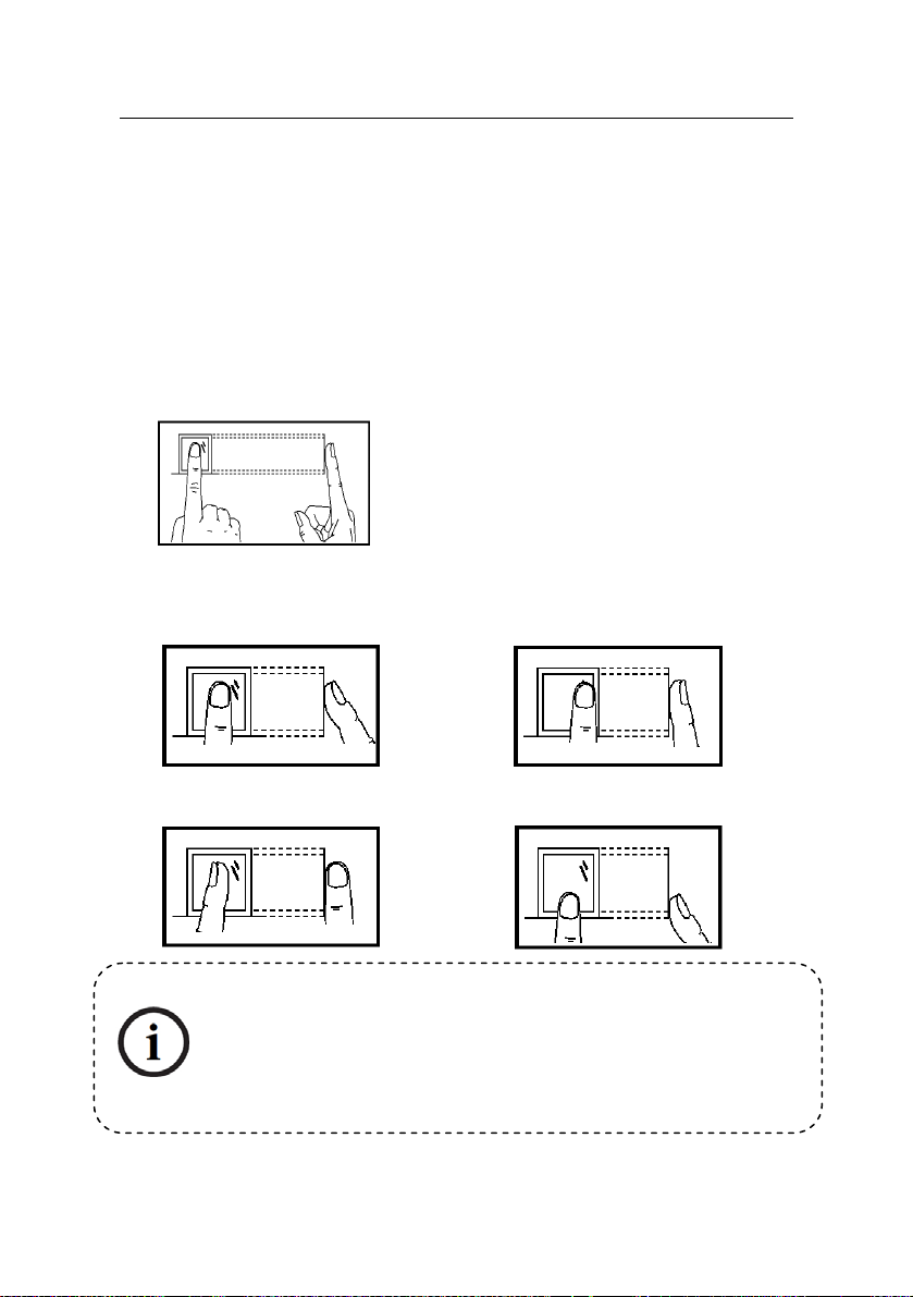
1.1 Finger Placement
Recommended fingers: The index finger, middle finger or the ring finger; the
thumb and little finger are not recommended (because they are usually
clumsy on the fingerprint collection screen).
1. Proper finger placement:
2. Imp
roper finger placement:
The finger is flat to the surface
and centered in fingered guide.
Not flat to the
surface
Slantin
Please enroll and verify your fingerprint by using the proper finger
placement mode. We shall not be held accountable for any
consequences arising out of the degradation in verification
performance due to improper user operations. We shall reserve the
right of final interpretation and revision of this document.
Off-center
Off-center
1
Page 6

User Manual V1.1
1.2 Instruction for Card Swipe
Integrated with a non-contact RF card reader module, this device supports
the ID cards and MIFARE cards (optional and only used as ID cards). By
offering multiple verification modes such as fingerprint, RF card and
fingerprint + RF card verification, this device can accommodate to diversified
user needs.
Swipe your card across the sensor area after the voice prompt and rem ove
your card after the device has sensed it. For the swipe area, see 2.2 Product
Appearance.
1.3 Precautions
Protect the device from exposure to direct sunlight or strong beam as strong
beam greatly affects the fingerprint collection and leads to fingerprint
verification failure.
It is recommended to use the device under a temperature of 0–50°C so as to
achieve the optimal performance. In the event of exposure of the device to
the outdoors for long periods of time, it is recommended to adopt sunshade
and heat dissipation facilities because excessively high or low temperature
may slow down the device operation and r esult in high false rejection rate
(FRR) and false acceptance rate (FAR).
When installing the device, please connect the power cable after connecting
other cables. If the device does not operate properly, be sure to shut down
the power supply before performing necessary inspection. Note that any
live-line working may cause damage to the device and the device damage
arising out of live-line working falls beyond the scope of our normal warranty.
For matters that are not covered in this document, please refer to related
materials including the installation guide, access control software user
manual.
2
Page 7
2. Introduction of Device
2. Introduction of Device
2.1 Overview of Device Functions
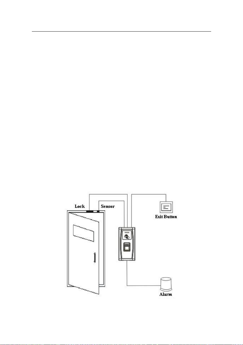
As an integrated fingerprint & access control device, our product can be
connected with either an electronic lock or an access controller. This device
features simple and flexible operations and supports the use of management
cards. With a management card, you can perform such functions as offline
enrollment, deletion and U-disk management. The voice prompts will guide
you through all the operations without screen displa y. This device allows you
to connect an external keyboard and offers multiple operation modes. It
supports access control function for a security management. It is supports
multiple communication modes. The U-disk features simple and convenient
operations. The waterproof design and metal case of the device allow it to
withstand a heavy impact without damage.
Featuring a compact and simple design, this device allows users to connect
several devices through a PC and perform real-time monitoring.
3
Page 8
User Manual V1.1
2.2 Product Appearance
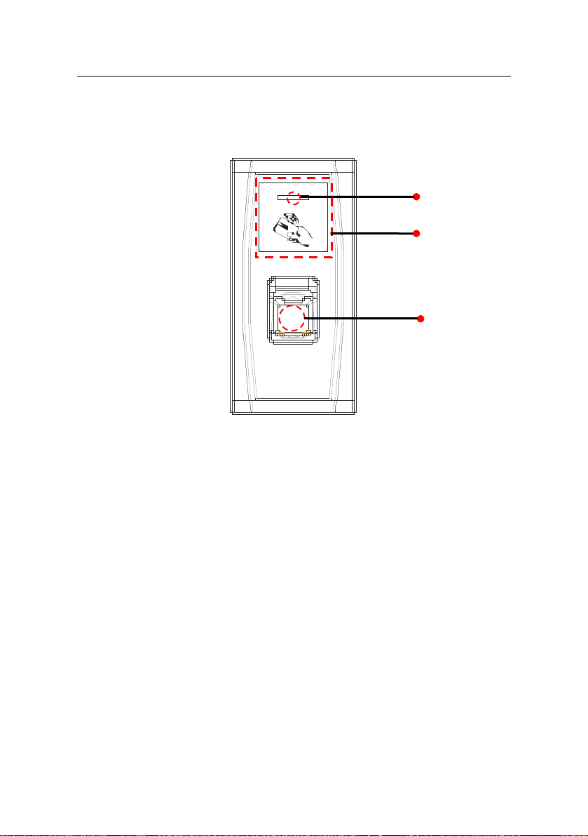
Front view:
LED Indicator
Swipe Card Area
FP Sensor
LED indicator: The LED indicator is used to display device operation
results and exceptional statuses which are defined as follows:
Common rules: If an operation succeeds, the green indicator
one second; otherwise, the red indicator is solid on for one second.
Enrollment state: The green LED blinks three times every oth
second.
Single u
second.
Verificati
Card Swipe area: Refers to the area in the red dashed-line bo
shown in the figure above.
Fingerprint sensor: U
users.
ser deletion: The red LED blinks three times every other three
on state: The green LED blinks once every other two second.
sed to collect and match fingerprints and delete
is solid on for
er three
x as
4
Page 9
2. Introduction of Device
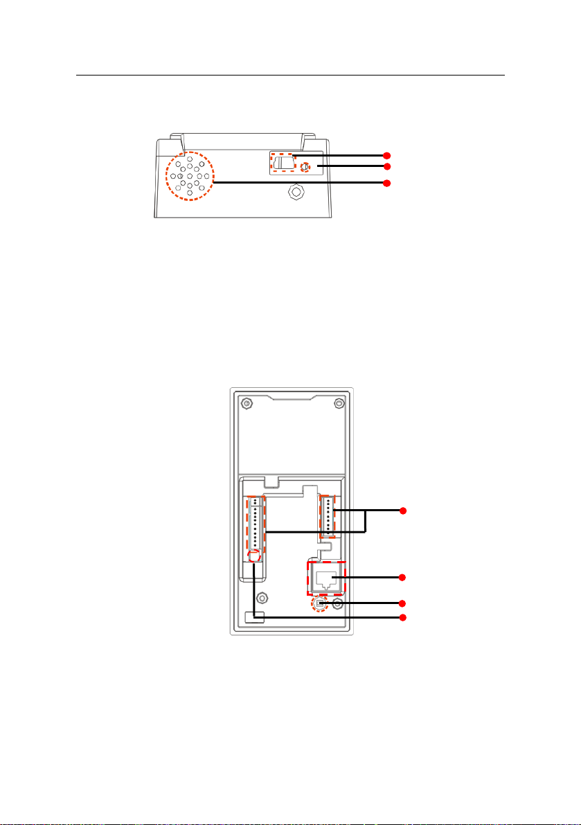
ottom view: B
USB Interface
Res
et Button
Speaker
USB interface: Used to connect with a U-disk or a keyboard.
Reset button: Used to restart the device.
Speaker: Used to play the BEEP sound and voice
passes the verification, the speaker beeps once; if the user fails to pass the
verification, the speaker beeps twice. The default prompts during operation:
beep + voice prompts.
Rear view:
prompts. If a user
iring terminals
W
T
CP/IP Interface
Tamper Switch
Wiring T
cables.
TC
network cable (for detailed connection, see the installation guide).
erminal: Connects with locks a d power sup h
P/IP Interface: The TCP/IP interface connects with a PC through a
n ply throug
DIP Switch
5
Page 10
User Manual V1.1
Tampe r S wit ch : Used to generate a tamper alarm. For details, see 3.6 Tampe r S wit ch : Used to generate a tamper alarm. For details, see 3.6
Tamper Switch.
DIP Switch: The DIP switch has four pins numbered 1, 2, 3 and 4. In
the RS485 communication mode, the first 1, 2 and 3 pins are used to set
hard
ware device number and the fourth pin is used to select the status of
terminal resistance. For detailed settings, see the installation guide.
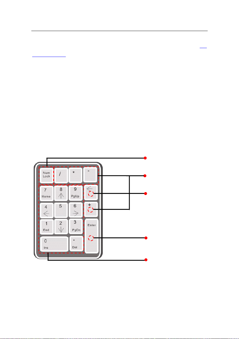
2.3 Use of an External USB Keyboard
To facilitate device operations, you can connect the devic
USB keyboard (purchased by users) and
oper
ations as user enrollment, deletion and restoring factory defaults,
especially when specifying user IDs during user enrollment and deletion
.
An external USB keyboard is shown abov actual
roduct):
p
NumLock is a numeric keypad toggle key. It is activated by default. If it is
conveniently perform such
e with an external
Shift Key
Operatio
Backspace
Enter key
Number keys 0-9 er keys 0-9
ase refer to the e (ple
nal Notation
6
Page 11

2. Introduction of Device
activated, the LED ind
external keyboard, you can only use the numerical keys, backspace key and
Enter key in the NumLock activated state.
icator is on. When the device is connected with an
2.4 Verification State
Verification state: After t
verification state if you hav
card or in the event of timeout of any operation.
In the verification state, all users are allowed to verify their identity and unlock
(the administrator bearing a management card c
fingerprint(s) previously enrolled); the administrator can perform such
operations as user enrollment/deletion, U-disk management and keyboard
operation.
he device is powered on, the device enters the
e enrolled or successfully enrolls a management
an only unlock using his/her
2.5 Management Card
The device users are classifi
Administrators: An admin
including user enrollment/deletion (deleting all the other users except him/h
and U-disk management. The privileges of the device administrators are
implemented through the management cards.
Ordinary users: Ordinary users are only allowed to verify their identity and
unlock.
A management card is a card specially allocated for a super administrator.
Each de
card is enrolled, you cannot perform any operation and the system will
generate a voice prompt “
You can implement different functions by swiping a management card
for different times in a row:
1. No U-disk or external keyboard are connected:
vice must at least enroll one management card. If no management
ed into administrators a
istrator is allowed to perform all operations
: Please register the management card”.
nd ordinary users.
er)
7
Page 12

User Manual V1.1
By swiping the management card once, you can go into the single user
llment state.
enro
By swiping the management card five times in a row, you can enter the
single user deletio
2. U-disk is connected:
By swiping the manage
management state.
3. An external keyboard is connected:
By swiping the m
keyboard.
Consecutive swipes: Consecutive swipes mean the interval between t wo
swipes in a
The management cards can be deleted through the “Clear All” function of the
keyboard, or have their administration priv
before they are deleted as ordinary ID cards. For details, see the access
control software user manual.
The fingerprints of the user who bears a management card can be enrol led
through software or keyboard enro
A device without management card, if it have the keyboard password, you
can activate the external keyboard and enro
n state.
ment card once, you can go into the U-disk
anagement card once, you can activate the external
row is less than 5 seconds.
ileges cleared through software
llment.
ll or delete users.
Note: Users who bear management cards can only verif
nlock using their fingerprints previously enrolled.
and u
2.6 System Password
A system password is a pa
data in TCP/IP or RS485 com
ssword used to enhance the security of device
munications.
y their identity
8
Page 13

2. Introduction of Device
Note: The system password can be modified through the access control
software. For details, see the access control software user manual.
2.7 Operation Timeout
The default operation timeout time is 30 seconds. When you enroll a
management card or delete/enroll a user (including in the external keyboard
enrollment and user deletion states), the system automatically prompts you
once every other 10 second if there is no operation and returns to the
verification state after prompting you three times. The voice prompt is “
Operation timeout. The system returns to verification state”.
:
Note: You can set the timeout time through the access control
software.
9
Page 14

3. Device Operations
3. Device Operations
3.1 Management Card
3.1.1 Enroll a Management Card
To enroll a management card, proceed as follows:
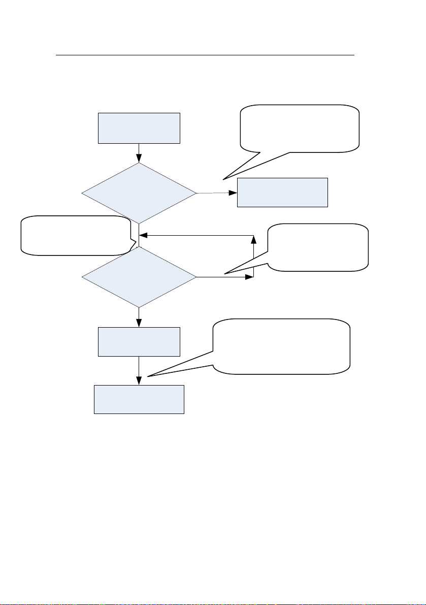
1. The device automatically detects whether there exists a management
card.
2. If the device fails to detect the presence of a management card, it
enters the management card enrollment state. Then proceed with step 3;
otherwise the system generates the voice prompt “
Please press your finger or punch your card”..
3. After the system generates the voice prompt “
management card”, you can swipe your card across the sensor area.
4. If enrollment fails, the system generates the voice prompt “
card number is repeated” and returns to step 3; if enrollment succeeds,
the system generates the voice prompt “
The system returns to verification state”.
: Registration is successful.
: Verify users.
: Please register the
: The
Note: The system returns to the verification state if any operation
in step 3 times out and only prompts you to enroll the management card
again after you restart the device again.
10
Page 15
3. Device Operations
The management card enrollment flow is shown below:
: Verify users. Please
System power-on
press your finger or
punch your card.
Does there
exist a management
card
: Please register the
management card.
3.1.2 Enroll an Ordinary User
No
Whether swipe a
new card
Yes
Enroll a
management card
Return to the
verification state
Yes
Verification State
: The card number
is repeated.
No
: Registration is successful.
The system returns to the
verification state.
The mode for you to enter the enrollment state using the management
card is known as the management card enrollment mode. In this mode,
you can only enroll one user. When you enroll a new user, the system
automatically assigns a minimum idle ID to the user. Furthermore, you
11
Page 16
User Manual V1.1
can also use the external keyboard enrollment mode (For details, see
3.2.2 Enroll a User Through Keyboard
specified ID.
In both these two enrollment modes, you can enroll new users. Each user
is allowed to enroll 10 fingerprints and one ID card at most.
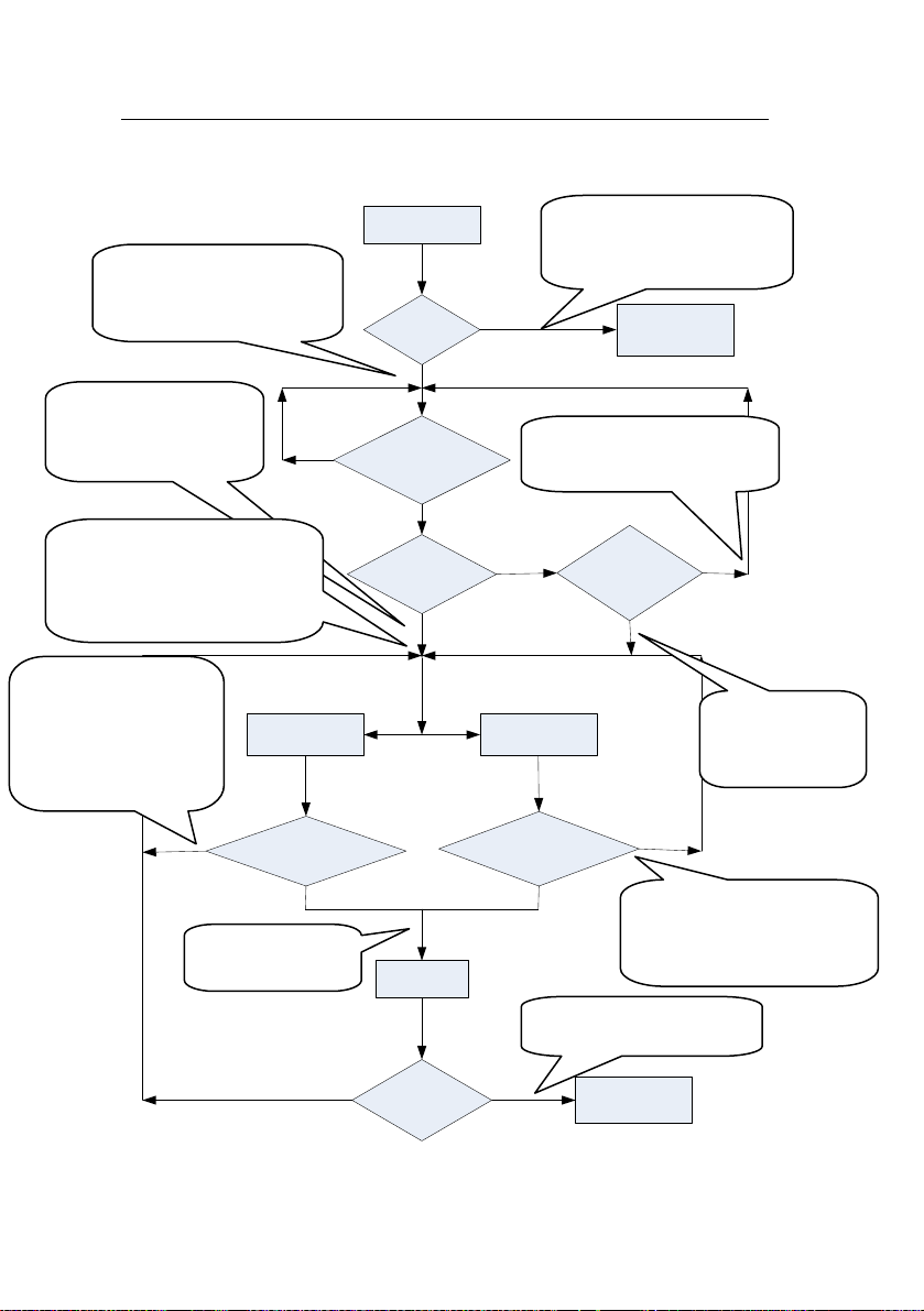
To enroll a user, proceed as follows:
1. In the verification state, the system goes into the ordinary user
enrollment state after you swipe a management card once (In the
enrollment state, swiping a management card once will return you to the
verification state).
2. After the system generates the voice prompt “
Please press your finger or punch your card”, you can start user
enrollment. There are the following two cases:
) to implement user enrollment of
: Register users.
:
“Register users. Please
press your finger or
swipe your card.
wipe ID card first
(1) S
a. When you swipe your new ID card and succeed in e nrolling a user, the
device will generate a voice prompt “
successful!” (** refers to the ID automatically assigned to the user by the
system; same below) and you can proceed to step b; if you swipe an
: User number **. Registration is
12
Page 17

3. Device Operations
lled ID card, , the system generates the voice prompt “
enro
number **, Register. Please press your finger!” and enter the specified
user enrollment state.
b. After the device generates the voice prompt “: Register. Please
press your finger”, the system enters the specified fingerprint enrollment
state. Press the same finger over the sensor three times following the
voice prompts.
c. If fingerprint enrollment succeeds, the system generates the voice
prompt “
finger” and directly enters the next fingerprint enrollment state; if
fingerprint enrollment fails, the system generates the voice prompt “
The fingerprint is repeated” and repeats step b.
d. The system automatically returns to the verification state when both 10
fingers and ID card are enrolled, or the management card is s wiped once
or operation times out.
(2) Press finger first
a. Press the same finger over the sensor three times following the voice
prompts by adopting the proper fingerprint placement. If fingerprint
enrollment succeeds, the system generates the voice prompt “
number **. Registration is successful” and you can proceed to step b; if
the fingerprint enrolled before, the system generates the voice prompt
“: User number **, Register, Please press your finger or punch your
card” and enter the specified user enrollment state.
b. After generating the voice prompt “
finger or punch your card”, the system enters the specified user
information enrollment state, waiting for you to swipe your new ID card or
press your finger.
c. If the ID card enrollment succeeds, the system generates the voice
prompt “
: Registration is successful. Register. Please press your
: Register. Please press your
: Registration is successful. Please press your finger” and
: User
:
: User
13
Page 18

User Manual V1.1
enters the fi
not enrolled before and succeeds in enrollment of this fing er, the system
generates the voice prompt: “
your finger or punch your card” and you can continue enrolling new
fingerprints and card. After you enroll 10 fingerprints, the system will
generate the voice prompt “: Please punch your card” to enroll your ID
card if your ID card is not enrolled.
d. The system automatically returns to the verification state when both 10
fingers and ID card are enrolled, or the management card is s wiped once
or operation times out.
3. If you are already assigned with a user number, then there are the
following two cases:
(1) Enroll fingerprint(s) when you have already enrolled card
a. After you swipe the enrolled card, the system will generate the voice
prompt “
to the ID assigned to you; same below) and enter the fingerprint
enrollment state..
b. Press the same finger over the sensor three times following the voice
prompts by adopting the proper fingerprint placement. If fingerprint
enrollment succeeds, the system generates the voice prompt “
number **. Registration is successful” and gets ready for enrollment of
next fingerprint.
c. The system automatically returns to the verification state when both 10
fingers and ID card are enrolled, or the management card is s wiped once
or operation times out.
ngerprint enrollment state directly; if you press a finger that is
: Registration is successful. Please press
: User number **. Register. Please press your finger” (** refers
: User
Note:
1) If the user enroll a fingerprint that is repeat with his own enrolled
fingerprint, the new one will overwrite the previously enrolled fingerprint.
14
Page 19

3. Device Operations
2) In this mod
card cannot be enrolled because swiping the management card will
return the system to the verification state automatically.
(2) Enroll card and fingerprint(s) when you have already enrolled
fingerprint(s)
a. Press the finger with fingerprint already enrolled three times following
the voice prompts. If you are identified as the same person in eac h of
verification attempt, the system enters the fingerprint enrollment state.
b. After generating the voice prompt “
Please press your finger or punch your card”, the system starts to enroll
your fingerprint.
c. If the ID card enrollment succeeds, the system generates the voice
prompt “
finger” and enters the fingerprint enrollment state directly; if you pr ess a
finger that is not enrolled before and succeeds in enrollment of this finger,
the system generates the voice prompt: “
Please press your finger or punch your card” and you can continue
enrolling new fingerprints and card. After you enroll 10 fingerprints, the
system will generate the voice prompt “: Please punch your card” to
enroll your ID card if your ID card is not enrolled.
d. The system automatically returns to the verification state when both 10
fingers and ID card are enrolled, or the management card is s wiped once
or operation times out.
e, the fingerprint of the user who bears the management
: User number **. Register.
: Registration is successful. Register. Please press your
: Registration is successful.
15
Page 20
User Manual V1.1
The flow chart is shown below:
: Register users. Please
press your finger or punch
your card.
: User number **.
Register. Please press
your finger.
Register. Please press your
finger or punch your card/
Please press your finger/
Please punch your card
: The number of
enrolled cards is full/
The card has been
registered/ The card
number is repeated
No No
: Registration is
successful
Enrollment state
The number
of users is full
No
No
Swipe card Press finger
Is the card enrollment
successful?
Press finger or
swipe card?
Yes
New fingerprint
or card?
No
Yes
Enrollment is
successful
Is the fingerprint
enrollment successful?
: The number of users is
full. The system returns to
verification state.
Yes
Return to the
verification state
: Please punch your card
again/ Please try again
Yes
Is new user
enrollment
successful?
Yes
: The number of enrolled
fingerprints is full/ The
fingerprint is repeated
: The system returns to
the verification state
No
: User number
**. Registration is
successful
Are both 10
No
fingers and card
enrolled?
Yes
Return to the
verification state
16
Page 21
3. Device Operations
p
3.1.3 Delete a Single User
Deleting a user by using a management card is called the simple
single-user deletion mode. Deleting a user by using an external
keyboard is called the specified user deletion mode. (See 3.2.3 Delete
a Specified User).
The operation steps for simple single-user deletion:
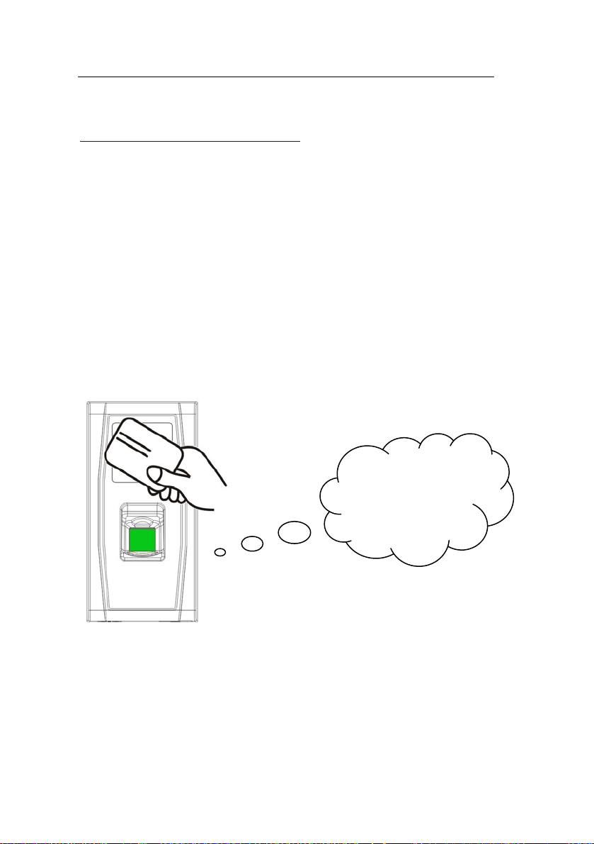
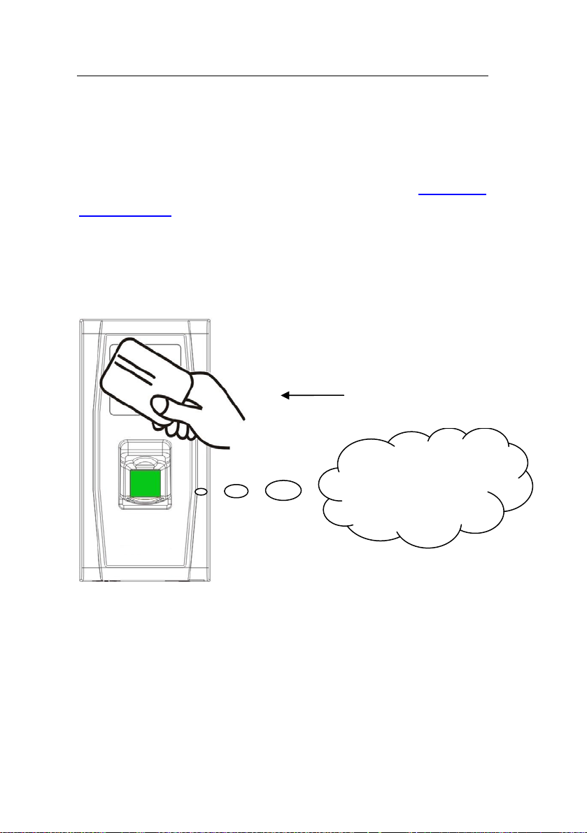
1. In verification state, swipe your management card for five consecutive
times to enter the simple single-user deletion state (swipe your card one
more time to return to the verification state).
Swipe your management card for
five consecutive times
“Delete users. Please
press your finger or
unchyour card.”
2. T
he system will generate the voice prompt “
press your finger or punch your card.”
3. Press your finger onto the fingerprint sensor or swipe your card over
the card reader.
(1) Press your finger onto the sensor to delete a user.
Press one of your enrolled fingers properly onto the sensor. If the
: Delete users. Please
17
Page 22

User Manual V1.1
verificati
User number **. Deletion is successful. Delete users. Please press your
finger or punch your card.” (** indicates the ID number of the user) and
automatically return to the deletion state. If the verification fails, the
system will generate the voice prompt “
(2) Swipe your card over the reader to delete a user.
Swipe a registered card over the reader. If the verification succeeds, the
system will generate the voice prompt “
successful. Delete users. Please press your finger or swipe your card.”
and automatically return to the deletion state. If the verification fails, the
system will generate the voice prompt “
again.”
4. If you swipe your management card one more time or your operation
times out, the system will return to the verification state.
on succeeds, the system will generate the voice prompt “
: Please try again.”
: User number **. Deletion is
: Please punch your card
:
Note: In simple single-user deletion mode, management card
users cannot be deleted because swiping the management card will
return the system to the verification state.
18
Page 23
3. Device Operations
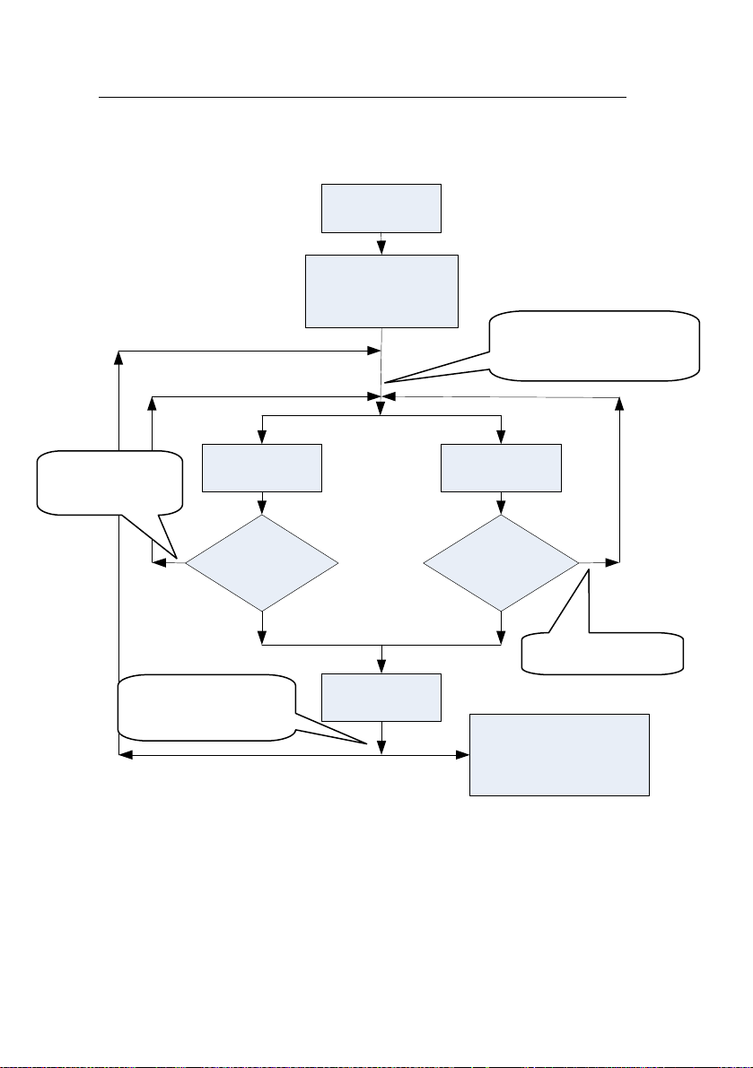
Simple Single-User Deletion Procedure:
Verification state
Enter the deletion state
after swiping the
management card 5
times in a row
: Delete users. Press your
finger or punch your card.
: Please punch
your card again.
: User number **.
Deletion is successful.
Card verification
No
Is card verification
successful?
Yes
Delete user
Fingerprint
verification
Is fingerprint
verification
successful?
Yes
No
:Please try again.
Return to the verification
state after the management
card is swiped once or
operation times out
19
Page 24
User Manual V1.1
3.2 USB Keyboard Operations
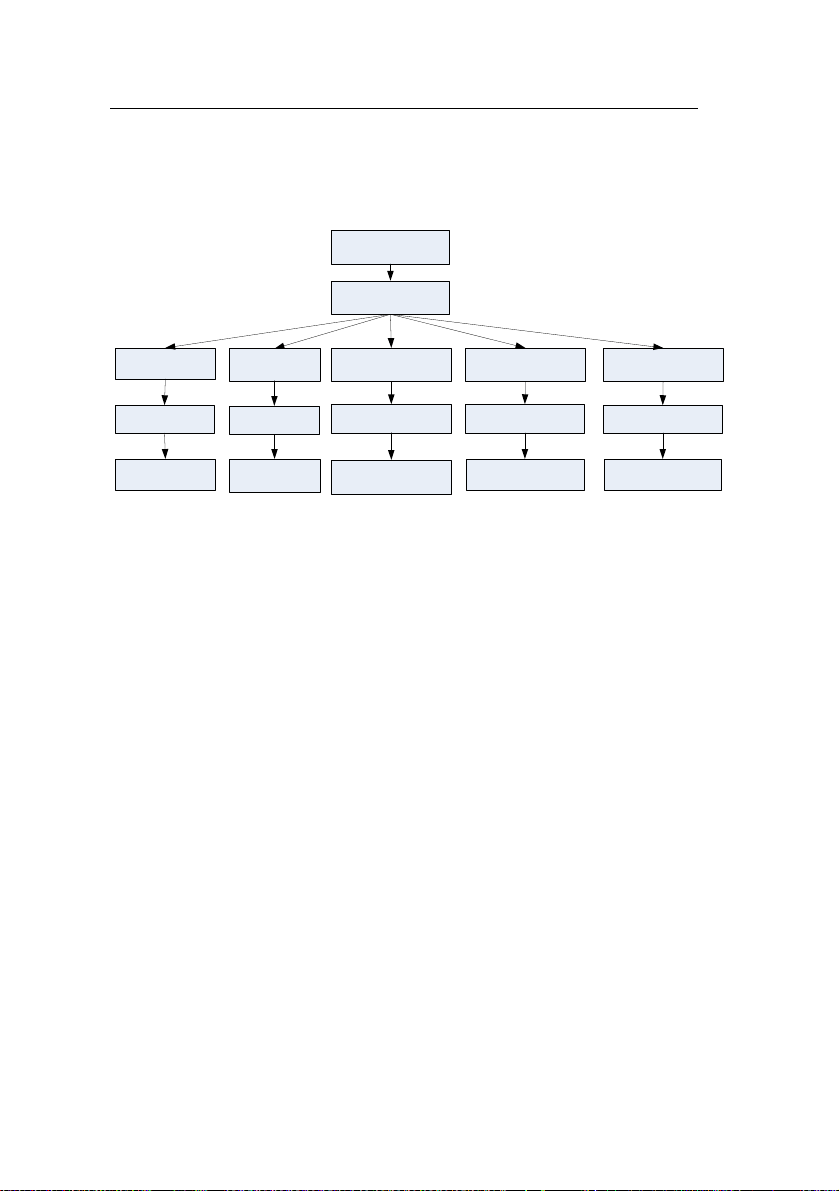
The keyboard operations flow chart is shown below:
Verification state
Password + Enter
1 + Enter
Enrollment state
Return to verification
state
2 + Enter
Single user deletion
state
Return to
verification state
3 + Enter + 3 + Enter 9 + Enter + 9 Enter
Restore factory defaults
Return to verification state
Delete all
Return to verification
state
8+ Enter + 8 + Enter
Enter password
Return to verification
state
3.2.1 Set Keyboard Password
If the user needs an external keyboard, he/she can connect the keyboard
to the device and then swipe the management card to activate the
external keyboard.
The system enables the user to set a dedicated password for the external
keyboard.
Operation steps:
1. In verification state, connect an external keyboard with the device
through the USB interface.
2. Swipe your management card once to activate the keyboard. The
system generates the voice prompt “
3. Type in “8” and press Enter. Then type in “8” and press Enter again.
The system generates the voice prompt “
in your desired password and press Enter. The system generates the
voice prompt “
: The operation is successful. The system returns to
: Please press the keyboard.”
: Please set password.” Type
20
Page 25

3. Device Operations
verificati
system will generate the voice prompt “
system returns to verification state.” (The password must be between 4
and 6 digits long.)
The user can enter this password to activate the functions of the external
keyboard at the next use, or swipe a management card once (which is
mandatory for the first use of the external keyboard).
1. If you enter a wrong password for six consecutive times, the keyboard will
be locked and you will have to power on the keyboard again to unlock it.
2. If there are no keystrokes within 3 seconds after the keyboard is activated,
the keyboard functions will be automatically deactivated and you will have to
reactivate it.
3. T
seconds, otherwise the system cannot identify its state.
on state.” If there are no keystrokes within 30 seconds, the
: Operation timeout. The
he keyboard must to be inserted or removed at an interval of over 15
3.2.2 Enroll a User Through Keyboard
Enrolling a user by using a USB keyboard is called keyboard based
enrollment mode. In this mode, the user can enroll a user with the
specified user ID.
Operation steps:
1. As shown in 3.2 USB Keyboard Operations flow chart, type in “1” and
press Enter to enter the enrollment state.
2. When the system generates the voice prompt “
Please input the user number.”, enter a user ID.
3. The system generates the voice prompt “
users. Please press your finger or punch your card.” (** indicates the ID
: User number **. Register
: Register users.
21
Page 26

User Manual V1.1
numb
er of the user; same below) The system enters the specified ID
enrollment state.
Note:
(1) If a user has enrolled in the system with a management card, the
system will generate the voice prompt “
your finger.”
(2) If a user has enrolled in the system with a user ID and 10 fingerprints,
the system will generate the voice prompt “: User number **. Please
punch your card.”
4. The user enroll operation in the specified ID enrollment state is similar
to the specified ID enroll operation in the management card enrollment
mode. For details, see 3.1.2 Enroll an Ordinary User
5. In the enrolled user ID standby state, press ESC to return to the
verification state. In the specified user ID enrollment state, press ESC
twice to return to the verification state.
: User number **. Please press
.
Note: In keyboard based enrollment mode, you can enroll users
consecutively. Upon successful enroll, the system automatically returns
to the enrollment state.
22
Page 27
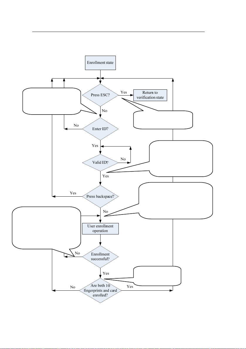
The keyboard based enrollment flow chart is shown below:
: Register user.
Please input the user
number.
: The number of records
is full/ The card number is
repeated/ The card has been
registered/ The fingerprint is
repeated.
3. Device Operations
: The system returns
to verification state.
: User number **.
Register. Please press your
finger or punch your card.
(Please press your finger.)
: Register. Please press your
finger or punch your card/
Please press your finger/
Please punch your card.
: Registration is
successful.
23
Page 28
User Manual V1.1
Important Statement:
1. In keyboard based enrollment mode, if any operation times out, the
system automatically prompts you of this operation once every other 10
second and returns to the verification state after prompting you three
times.
2. Newly enrolled fingerprints will overwrite the original ones in
management card based enrollment mode, and keyboard based
enrollment mode likewise.
3. A user can only enroll one card. When the user with an enrolled card
enrolls in the system, the system generates the voice prompt “
Register. Please press your finger.” When the user swipes the card, the
system generates the voice prompt “
4. One card cannot be enrolled repetitively, otherwise the system will
generate the voice prompt “
card swiping. Different users cannot enroll the same fingerprint, otherwise
the system will generate the voice prompt “
repeated.” during fingerprint enrollment. A user’s new fingerprints will
overwrite the existing ones.
The difference between two user enrollment modes with respect to the enrollment
exit state:
1. In management card based enrollment mode with a specified user ID, the
system returns to the verification state after you swipe your card once.
2. In keyboard based enrollment mode with a specified user ID, when you press
ESC, the system returns to the enrollment state and generates the voice prompt
“
: Register users. Please input the user number.” You can enroll a user ID and
press ESC. Then the sy stem generates the voice prompt “
to verification state.”
: The card has been registered.”
: The card number is repeated.” during
: The fingerprint is
: The syste m ret urns
:
24
Page 29

3. Device Operations
3.2.3 Delete a Specified User
Deleting a user by using an external keyboard is called the specified
user deletion mode.
Operation steps:
1. Connect a USB keyboard to the device, and swipe your management
card once or enter your password to activate the keyboard.
2. Press “2” and Enter to enter the specified user deletion mode. the
system will generate the voice prompt “
user number.” and you may proceed to the step3.
: Delete users. Please input the
Notice: Special case: If there are no user (include management
card user) enrolled, and you have the keyboard password, you can use
the password to activate the keyboard and press 2 and Enter to enter the
user deletion state, the system will generate the voice prompt “
registered user. The system returns to verification state.”
3. Enter a user ID and the system checks whether the user ID is valid.
4. If the user ID is valid, the system will generate the voice prompt “
User number **. Deletion is successful. Delete users. Please input the
user number.” and automatically return to the deletion state. If the user ID
is invalid, the system will generate the voice prompt “
6. If you press ESC or your operation times out, the system will return to
the verification state.
: Wrong user ID.”
: No
:
Note:
1) In specified user deletion mode, user IDs and management card user
IDs that are enrolled in the system are all deemed invalid.
2) In keyboard based deletion mode, the system disable the fingerprint
sensor and card reader and therefore any operation on them is invalid.
25
Page 30
User Manual V1.1
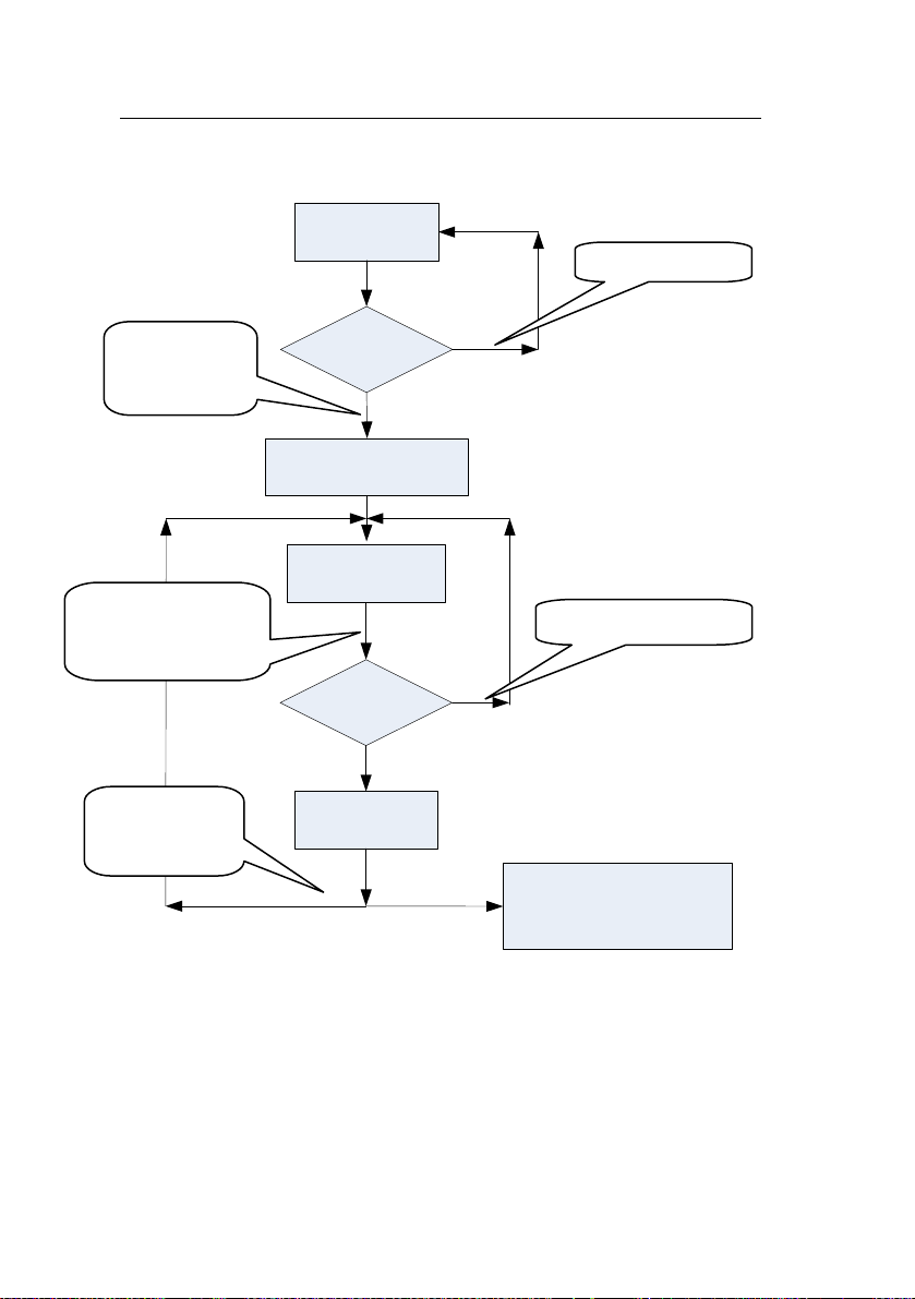
The specified user deletion flow chart is shown below:
Verification
state
: Password error
: Password
confirmation is
successful.
:Delete users.
Please input the user
number.
: User number
**. Deletion is
successful.
Activate
keyboard
Yes
Press 2 + Enter to enter
the deletion state
Enter ID?
Valid ID?
Yes
Delete user
No
: User number error.
No
Return to the verification
state if Backspace is press
or operation times out
26
Page 31

3. Device Operations
3.2.4 Delete All Users
Operation steps:
1. Connect a USB keyboard to the device, and swipe your management
card once or enter your password to activate the keyboard.
2. Press “9” and Enter. Then press “9” and Enter again. The system
deletes all the users.
3. If the operation succeeds, the system will generate the voice prompt
“
: Delete all users. The operation is successful. The system returns to
verification state. Please register the management card.”
Note:
1) You can delete a management card using the Delete All function.
2) You can use the Delete All function to delete all enrolled users,
fingerprints and records.
3). Extreme caution should be exercised while performing this operation,
as once deleted, the data cannot be recovered.
3.2.5 Restore Factory Defaults
Operation steps:
1. Connect a USB keyboard to the device, and swipe your management
card once or enter your password to activate the keyboard.
2. Press “3” and Enter. Then press “3” and Enter again. The system
restores the factory defaults.
3. After the operation succeeds, the system generates the voice prompt
“
: Restore to default settings. The operation is successful. The system
returns to verification state.”
You can also restore the factory defaults by resetting the tamper switch.
See 3.6 Tamper Switch
.
27
Page 32

User Manual V1.1
Af
ter the device is restored to factory defaults, the device information is
restored to factory defaults, including the device number, system
password, IP address, 485 address, and keyboard password.
Note: The user information stored on device will not be cleared after
the device is restored to factory defaults.
3.3 Access Control Function
Access control setting is to set user’s open door time zone, control lock
and related device’s parameters.
To unlock, the enrolled user must accord with the following conditions:
1. The current unlock time should be in the effective time of user time
zone or group zone.
2. The group where user is must be in access control (or in the same
access control with other group, to open the door together).
The system default the new enrolled user as the first group, default group
time zone as 1, access control as the first group, and the new enrolled
user is in unlock (User can modify the related setting of access control,
through access control software).
Notice: The device access control function n eed to set and modif y
through the access control software, for detail, please refer to the
software user manual.
Access Control Function:
1. Access Control Time Zone:
Time zone is the minimum unit of access control option. The whole
system can define 50 time zones. Every time zone defines seven time
sections (namely, a week). Every time section is the effective time zone
within 24 hours everyday. Every user can set 3 time zones. “or” exists
28
Page 33

3. Device Operations
amon
g the three zones. It is effective if only one is satisfied.
2. Access Holiday Setting:
Special access control time may need during holiday. It is different to
modify everybody’s access control time. So a holiday access control time
can be set, which is applicable for all employees.
3. Access Group Time Zone:
Grouping is to manage employees in groups. Employee in groups use
group time zone by default. Group members can also set user time zone.
Every group can hold there time zones. The new enrolled user belongs to
Group 1 by default and can also be allocated to other groups.
4. Unlock Combination Setting:
Make various groups into different access controls to achieve
multi-verification and improve security. An access control can be made up
of 5 groups at most.
5. Access Control Parameters:
Lock Control Delay: Apply to determine unlock hour, the min measured
unit is20ms, in the normal condition is 100-200ms.
Anti-Pass Mode: Can be set to "None", "Out ", “In”, “InOut”.
Master’s record state: Can be set to “None”, “Out”, “In”.
Sensor Mode: Set Door Sensor Mode. It can be set to “None”, “NOpen”,
“NClose” state.
Sensor Delay: Set the sensor delay time when the door is opened. After
this defined time the sensor detect the door state. If the door state is not
consistent the alarm will be triggered. Black and white screen device
range is 0-254. Color screen device range is 0-99.
Sensor Alarm: Set the alarm time delay after the alarm is triggered.
Range is 0-999 seconds.
Error times to alarm: Define the max error times to trigger alarm. When
the verify is not through, and exceed this defined times, the alarm signal
29
Page 34

User Manual V1.1
w
ill be triggered automatically.
6. Anti-Pass back setting:
Anti-Pass back function please refer to 4.2 Anti-Pass back
.
7. Disable alarm:
When the device is in alarm state, user’s verification can disable the
alarm, and the device will recover normal state. If not, it will alarm all the
time.
Alarm types: door sensor alarm and tamper alarm.
3.4 User Verification
The default verification of device is FP/RF verification, user can use the
access control software to modify the verify mode to RF, FP or RF&FP
verification. For detail please refer to the software user manual.
Operation steps:
1. When the device is in verification state, the system generates the voice
prompt “
2. Start user verification. The device supports four verifications modes:
FP/RF, FP, RF and FP&RF verification.
(1) Fingerprint verification
Press your finger on the fingerprint sensor in a proper way. If the
verification succeeds, the system generates the voice prompt “
number **. Thank you.” and concurrently triggers an unlocking signal. If
the verification fails, the system generates the voice prompt “
try again.”
(2) Card verification
Swipe your card over the card reader. If the verification succeeds, the
system generates the voice prompt “
and concurrently triggers an unlocking signal. If the verification fails, the
system generates the voice prompt “
: Verify users. Please press your finger or punch your card.”
: User
: Please
: User number **. Thank you.”
: Please punch your card again.”
30
Page 35

3. Device Operations
(3) F
ingerprint + Card verification
Set the user verification mode to FP & RF through access control
software, the verify operation as follows:
Press finger first:
Press your finger on the fingerprint sensor in a proper way. If the
verification succeeds, the system generates the voice prompt “
number **, Please punch your card.” after card verification succeed,
and concurrently triggers an unlocking signal. If the verification fails, the
system generates the voice prompt “: Please punch your card again.”
Swipe card first:
Swipe your card over the card reader. If the verification succeeds, the
system generates the voice prompt “
your finger.” After fingerprint verification succeed, and concurrently
triggers an unlocking signal. If the verification fails, the system generates
the voice prompt “
(4) Fingerprint or Card verification
That is, the verification operation of (1) or (2) both effective.
: Please try again.”
: User number **, Please press
: User
31
Page 36
User Manual V1.1
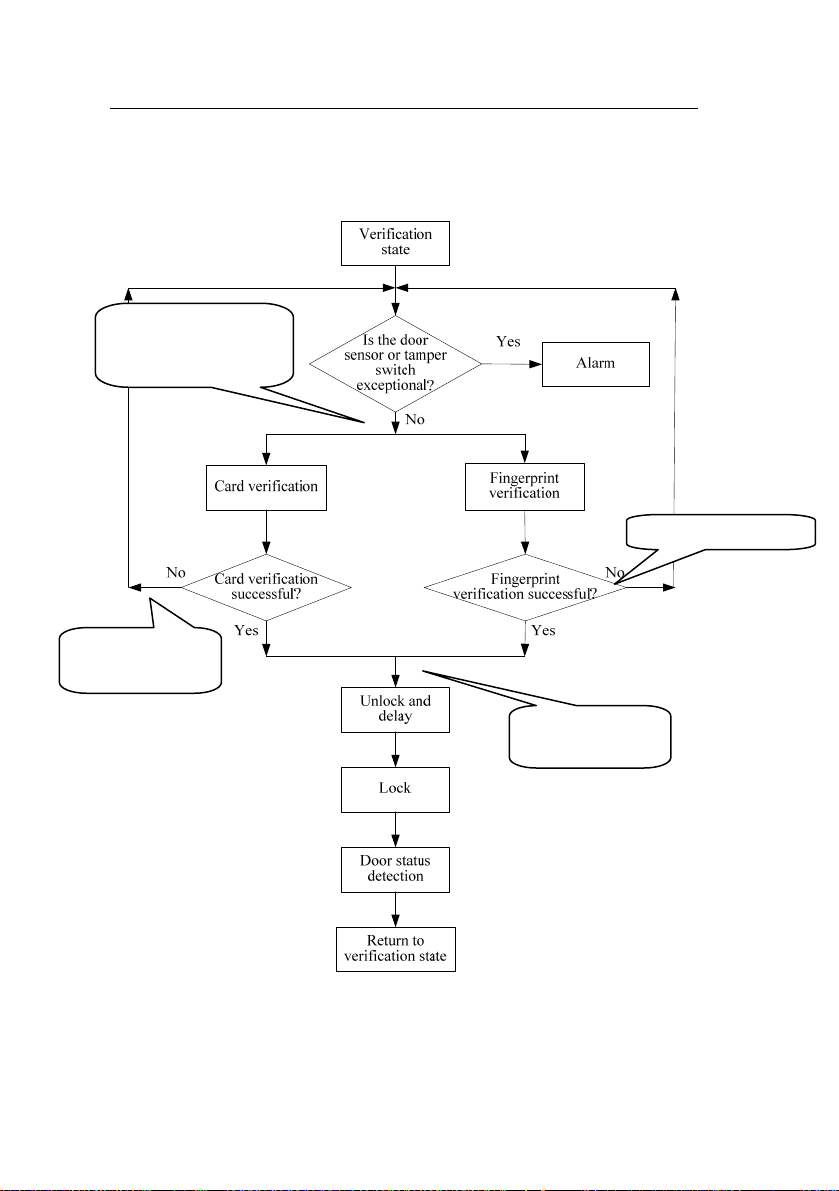
The user verification flow chart is show as below:
: Verify users. Please
press your finger or
punch your card.
: Please punch
your card again.
: Please try again.
: User number
**,Thank you.
32
Page 37

3. Device Operations
Tip:
(1) If the user is not in the effective access control time zone, he can not
verify and unlock the door, the system generates the voice prompt “
Invalid Time Zone.”
(2) If the user is not use the set verification mode to verify, he can not
verify and unlock the door, the system generates the voice prompt “:
Invalid Verification Mode.”
3.5 U-disk
The user can perform record download, user download, user upload,
and firmware upgrade through a U-disk.
a. Record download: Download the attendance records of all users from
the device to a U-disk.
b. User download: Download all user information such as fingerprints
and card numbers from the device to a U-disk.
c. User upload: Upload the user information from a U-disk to the device.
d. Firmware upgrade: Upgrade the device firmware through a U-disk.
The configuration files in the U-disk can be created and modified by using
the access control software. The operation please refer to the software
user manual.
Notice: Please do not upgrad e the firmware at your discretion because
it may bring problems and affect the normal use of the device. Contact
our distributors for technical support or upgrade notification.
:
33
Page 38

User Manual V1.1
U-disk operations include the following two cases:
1. If you connect a U-disk without configuration file to the device, the
system will automatically prompt you of the operations in sequence.
(1) After connecting a U-disk to the device, you can swipe your card once
to enter the U-disk management state.
(2) The system generates the voice prompt “
management card for confirmation.” (**** indicates the four operation
items from a to d in sequence; same below)
(3) If you want to perform U-disk management, swipe your card for
confirmation. If your operation succeeds, the system will generate the
voice prompt “
proceed to the next step. After you finish the four items, the system
generates the voice prompt “
If your operation fails, the system will generate the voice prompt “
operation fails. The system returns to verification state.”
(4) If you do not swipe your management card, the system will
automatically skip over this step upon 5 seconds and prompt you of the
next step. After you finish the four items, the system returns to the
verification state automatically.
2. If you connect a U-disk with configuration file to the device, the system
will carry out operations based on the settings of the configuration file.
(1) After connecting a U-disk to the device, you can swipe your card once
to enter the U-disk management state.
(2) The system obtains operation commands by reading the configuration
file on the U-disk and generates the voice prompt “
files in the U-disk. Please swipe your management card for confirmation.”
(3) After you swipe your card and perform all operations successfully, the
system will generate the voice prompt “
successful.” in sequence for every operation step. If any of the operations
: The operation is successful.” and prompt you to
: The system returns to verification state.”
: ****. Please punch your
: The
: Run configuration
: ****. The operation is
34
Page 39

3. Device Operations
fails, the system will generate the voice prompt “
fails.”
(4) After you finishing all the operations, the system generates the voice
prompt “: The system returns to verification state.”
: ****. The operation
Notice: Please wait 8 seconds after you insert the U-disk into the
device, otherwise, the system can’t detect the U-disk probably.
3.6 Tamper Switch
T
he tamper switch is pressed and held down with a rear cover. When the
device is dismantled, the tamper switch will be lifted up and then it will
send an alarm signal to trigger an alarm.
Clear alarm: The user can clear the alarm by unlocking the door upon
successful matching.
Restore factory defaults: The factory defaults can be restored through
the tamper switch.
When the system generates an alarm for 30–60 seconds, the user can
press the tamper switch three times (till the speaker sounds) to restore
default settings, including the device number, system password, IP
address, 485 address, and keyboard password.
Note:
1. The user information stored on device will not be cleared after the
device is restored to factory defaults.
2. The factory defaults can be restored through the USB keyboard. For
details, see 3.2.5 Restore Factory Defaults.
35
Page 40

4. Appendix
4. Appendix
4.1 List of Parameters
The following table lists the basic functional parameters of the device.
Item Note
Power Supply 12V 3A
Access control device, door sensor/ alarm/ lock/ exit
Function
User quantity 10000 (fingerprint and ID card)
Record capacity 100000 pieces of records
Enrollment
capacity
(fingerprint/card)
Verification mode. ID (Mifare) card, fingerprint, fingerprint + card
Communications TCP/IP, RS485, U-disk
Speaker Voice, BEEP
LED Bi-color indication (red/green)
Keyboard Valid keys: 0-9, Enter, ESC
button
One Wiegand input and one Wiegand output
1500 fingerprints/10000 cards
36
Page 41
4. Appendix
4.2 Anti-Pass Back ★
[Overview]
Sometimes, some illegal person follows the other one into the gate, which
will bring security problem. To prevent such risk, this function is enabled.
In record must match out record, or the gate won’t be open.
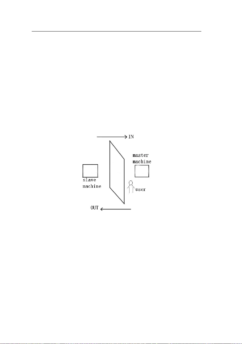
This function needs two machines to work together. One is installed
inside the door (master machine hereinafter), the other is installed outside
the door (slave machine hereinafter). Wigand signal communication is
adopted between the two machines.
[Working principle]
The master machine has Wigand In and slave machine has Wigand Out.
Connect Wigand Out of slave machine to Wigand In of master machine.
Wigand output from slave machine must not own machine ID. The
number sent to master machine from slave machine must be found in the
master mach
[Function]
Judge whether it is anti-pass back according to user’s recent in-out
record. In record and out record m
ine.
ust be matched. This machine supports
37
Page 42

User Manual V1.1
out, in, or out-i
When master machine is set as “out anti-pass back”, if user wants to
come in and go out normally, his recent record must be “in”, or he cannot
go out. Any “out” record will be “anti-pass back refused”. For example, a
user’s recent record is “in”, his second record can be “out” or “in”. His
third record is based on his second record. Out record and in record must
match (Notice: If customer has no any record before, then he can come
in but cannot go out).
When the master machine is set as “in anti-pass back”, if the user wants
to come in and go out normally, his recent record must be “out”, or he
cannot go out. Any out record will be “anti-pass back refused” by the
system (Notice: If the
but cannot come in).
When the master machine is set as “out-in anti-pass back”, if the user
wants to come in and go out normally , if his rec
then his next rec
【operation】
1. Select model
Master
reader.
Slave machine: Machine with Wiegand Out function.
2. Set anti-pass back direction and device st
3. Modify device’s Wiegand output format
When the two devices a
device ID are rec
4. Enroll user
The user must be on master machine and slave machine at the same
time, and user PIN must be the same. Therefore, it is necessary
user on master machine and
n anti-pass back.
customer has no former record, then he can go out,
ent record is “out” and “in”,
ord must be “ in” and “out”.
machine: Machine with Wiegand in function, except for F10
atus.
re communicating, only Wiegand signals without
eived.
to enroll
slave machine at the same time.
38
Page 43

4. Appendix
5. Co
nnection instruction
Wiegand communication is adopted for mas
machine. Refer to the fo
llowing for connection:
Master Slave
IND0 <-----> WD0
IND1 <-----> WD1
GND <-----> GND
ter machine and slave
Notice: You can only set the anti-pass back parameters through the
ontrol
access c
anual.
m
software, for detail please refer to the software user
39
Page 44

4. Appendix
4.3 Statement on Human Rights and Privacy
Dear Customers:
Thank you for choosing the hybrid biometric products designed and
manufactured by us. As a world-renowned provider of biometric technologies
and services, we pay much attention to the compliance with the laws related
to human rights and privacy in every country while constantly performing
research and development.
We hereby make the following statements:
1. All of our fingerprint recognition devices for civil use only collect the
characteristic points of fingerprints instead of the fingerprint images, and
therefore no privacy issues are involved.
2. The characteristic points of fingerprints collected by our products cannot be
used to restore the original fingerprint images, and therefore no privacy
issues are involved.
3. We, as the equipment provider, shall not be held legally accountable,
directly or indirectly, for any consequences arising due to the use of our
products.
4. For any dispute involving the human rights or privacy when using our
products, please contact your employer directly.
Our fingerprint products or development tools for police use support the
collection of the original fingerprint images. As for whether such a type of
fingerprint collection constitutes an infringement of your privacy, please
contact the government or the final equipment provider. We, as the original
equipment manufacturer, shall not be held legally accountable for any
infringement arising thereof.
Note: The law of the People’s Republic of China has the following
regulations regarding the personal freedom:
40
Page 45

4. Appendix
1. Unlawful arrest, detention or search of citizens of the People's Republic of
China is prohibited; infringement of individual privacy is prohibited.
2. The personal dignity of citizens of the People's Republic of China is
inviolable.
3. The home of citizens of the People's Republic of China is inviolable.
4. The freedom and privacy of correspondence of citizens of the People's
Republic of China are protected by law.
At last we stress once again that biometrics, as an advanced recognition
technology, will be applied in a lot of sectors including e-commerce, banking,
insurance and legal affairs. Every year people around the globe suffer from
great loss due to the insecurity of passwords. The fingerprint recognition
actually provides adequate protection for your identity under a high securit y
environment.
41
Page 46

4. Appendix
4.4 Environment-Friendly Use Description
Names and Concentration of Toxic and Hazardous Substances or Elements
Parts Name
Chip resistor
Chip capacitor ×
Chip inductor ×
Chip diode ×
ESD components ×
Buzzer ×
Adapter ×
Screws
: Indicates that this toxic or haz ardous substance co ntained in all of th e homogeneous
materials for this part is below the limit requirement in SJ/T11363-2006.
×: Indicates that this toxic or hazardous substance contained in at least one of the
homogeneous materials for this part is above the limit requirement in SJ/T11363-2006.
The Environment Friendly Use Period (EFUP) marked on this product refers
to the safety period of time in which the product is used under the conditions
specified in the product instructions without leakage of noxious and harmful
substances.
The EFUP of this product does not cover the consumable parts that need to
be replaced on a regular basis such as batteries and so on. The EFUP of
batteries is 5 years.
Toxic and Hazardous Substances or Elements
Pb Hg Cd Cr6+ PBB PBDE
×
Note: 80% of the parts in this product are manufactured with non-hazardous
environment-friendly materials. The hazardous substances or elements contained cannot
be replaced with environment-friendly materials at present due to technical or economical
constraints.
42
 Loading...