

Grandhall IT2612ALP Operator's Manual
Failure to comply with these instructions could result
in a fire or explosion that could cause serious bodily
injury, death or property damage.
Whether this grill was assembled by you or someone
else, you must read this entire manual before using
your grill to ensure the grill is properly assembled,
installed and maintained.
Use your grill at least 3 feet away from any wall
or surface. Use your grill at least 3 feet away from
combustible objects that can melt or catch fire such
as vinyl or wood siding, fences and overhangs or
sources of ignition including pilot lights on water
heaters and live electrical appliances.
THIS GAS APPLIANCE IS DESIGNED FOR OUTDOOR USE ONLY.
Never use your gas grill in a garage, porch, shed,
breezeway or any other enclosed area.
Never obstruct the flow of ventilation air
around your gas grill housing.
Never disconnect the gas regulator or any gas fitting
while your grill is lit. A lit grill can ignite leaking gas
and cause a fire or explosion which could result in
property damage, personal injury or death.
Ÿ
Ÿ
Ÿ
Ÿ
Ÿ
Ÿ
WARNING
! !
Ÿ
Manual # P80151130A - Date:2012/02/22
Operator's Manual
Liquid Propane Gas (LPG) Grill
Models IT2612ALP
FREE HELP
FROM THE GRILL EXPERTS
Grand Hall is the expert on this product and
trained to help you with:
visit www.grandhall.com or call:
1-877-934-7455
Monday - Friday 8:00am-4:30pm CST
Assembly Questions
Grill Operation
Replacement of Damaged or Missing parts
Ÿ
Ÿ
Ÿ
NOTE TO ASSEMBLER / INSTALLER:
Leave this manual with the consumer.
NOTE TO CONSUMER:
Keep this manual for future reference.
RECORD YOUR SERIAL #
__________________
(see silver CSA label on the cart bottom panel)
Ÿ
Ÿ
IMPORTANT:
Ÿ
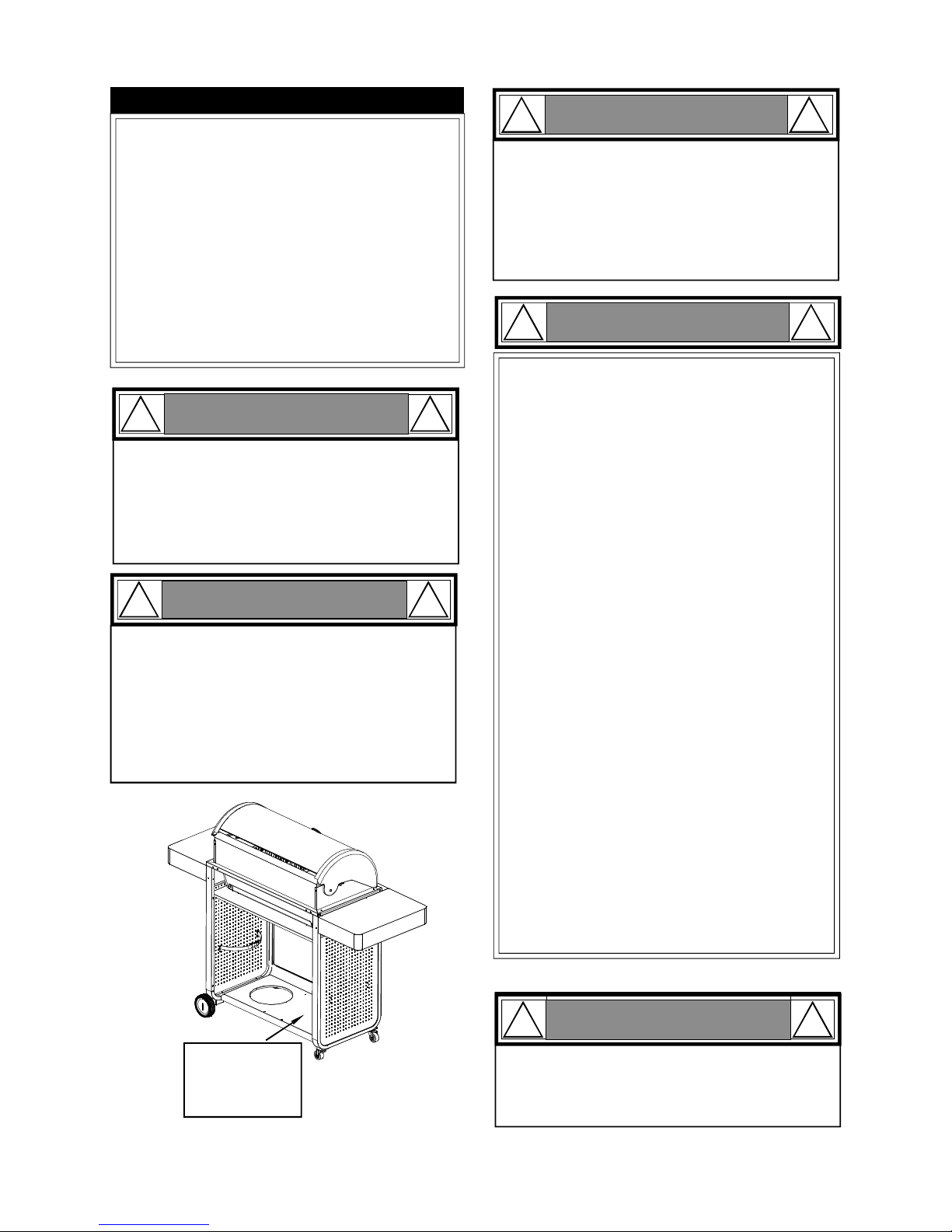
Table of Contents
Primary Safety Warnings..............................1-3
Pre-Assembly Instructions................................3
Parts Diagram and Lists.............................4-6
Assembly Instructions..................................7-10
Use & Care Instructions:
• Gas Safety and Leak Tests................11-13
• Lighting Instructions..................................14
• Troubleshooting............................................15
Cleaning and Maintenance.......................16-17
Cooking Guide..........................................A1-A4
Frequently Asked Questions..................A5-A6
Warranty Terms.................................Back Cover
2
Do not store or use gasoline or other
flammable liquids or vapors in the
vicinity of this or any other appliances.
An LP cylinder not connected for
use shall not be stored in the vicinity
of this or any other appliance.
1.
2.
•
LPG models must be used with Liquid Propane
Gas and the regulator assembly supplied. Natural
Gas models must be used with Natural Gas only.
Any attempt to convert the grill from one fuel type
to another is extremely hazardous and will void the
warranty.
Keep gas regulator hose away from hot grill surfaces
and dripping grease. Avoid unnecessary twisting of
hose. Visually inspect hose prior to each use for cuts,
cracks, excessive wear or other damage. If the hose
appears damaged do not use the gas grill. Call 1877-934-7455 for a certified replacement hose.
California Proposition 65
Combustion byproducts produced when using this
product contain chemicals known to the State of California to cause cancer, birth defects, or other reproductive
harm.
Brass components on the grill, such as hose fittings,
propane cylinder valves (sold separately) and burner
valve stems, contain lead which is known to the State of
California to cause cancer, birth defects, or other reproductive harm.
Never use charcoal or lighter fluid in this gas grill.
Failure to comply with these instructions could result in
a grease fire or explosion that could cause serious
bodily injury, death or property damage.
Before each use of your grill: Inspect the Grease
Receptacle and inside of the Grill Bowl to be sure there
is no excessive grease and debris buildup. Clean the
Grease Receptacle and inside of the Grill Bowl frequently to eliminate grease/debris build-up and to
prevent grease fires. Failure to comply with these
instructions could result in a grease fire and even a
subsequent that could cause serious bodily injury,
death or property damage.
•
•
•
•
!
This appliance, when installed, must be electrically grounded in accordance with local codes
or, in the absence of local codes, with the
National Electrical Code, ANSI/NFPA 70, or the
Canadian Electrical Code, CSA C22.1.
Keep any electrical supply cord and the fuel
supply hose away from any heated surfaces.
•
•
WARNING
!
DANGER
!
!
1.
2.
3.
4.
If you smell gas:
Shut off gas to the appliance.
Extinguish any open flame.
Open lid.
If odor continues, keep away from
the appliance and immediately call
your gas supplier or your fire
department.
WARNING
! !
WARNING
! !
Never cover or wrap the Cooking Grids, bottom of
the Grill Bowl, or Grease Receptacle with aluminum foil or any other material that will absorb
grease.
! !
WARNING
CSA Label
located on left
side of bottom
panel
Pre-Assembly Instructions For Your Safety
CAUTION
! !
Failure to comply with these instructions may result
in a hazardous situation which, if not avoided, may
result in injury.
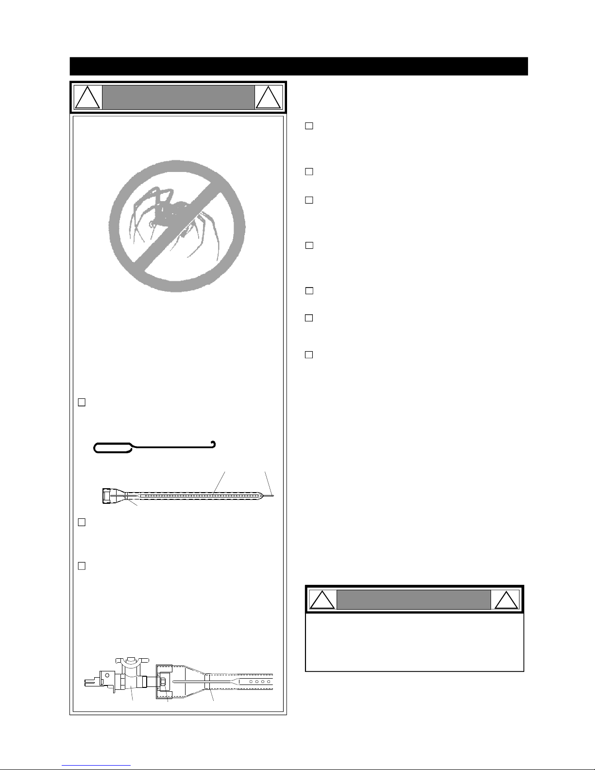
For safe operation ensure the Gas Valve Assembly Orifice is inside the Burner Tube before using
your grill. See figure. If the Orifice is not inside
the Burner Tube, lighting the Burner may cause
explosion and/or fire resulting in serious bodily
injury and/or property damage.
METHOD 1: Bend a stiff wire or wire coat hanger
into a small hook as shown and run the hook
through the Burner Tube and inside the Burner
several times to remove debris.
METHOD 2: Use a bottle brush with a flexible
handle and run the brush through the Burner
Tube and inside the Burner several times to
remove any debris.
METHOD 3: Use an air hose to force air through
each Burner Tube. The forced air should pass
debris or obstructions through the Burner and out
the Ports.
3
1.
2.
3.
4.
Refer to the figure below and perform one of these
3 cleaning methods:
Carefully lift each Burner up and away from the Gas
Valve Orifice.
Check and clean Burner/Venturi Tubes for insects
and insect nests. A clogged tube can lead to a fire
beneath the grill.
Spiders and small insects can spin webs and nest
in the grill Burner Tubes during transit and warehousing which can lead to a gas flow obstruction
resulting in a fire in and around the Burner Tubes.
This type of "FLASHBACK FIRE" can cause serious
grill damage and create an unsafe operating condition for the user.
To reduce the chance of FLASHBACK FIRE
you must clean the Burner Tubes as follows
before initial use. Also do this at least once a
month in summer and fall or whenever spiders are
active in your area, and if your grill has not been
used for an extended period of time.
Remove the screws from the rear of each Main Burner
using a Phillips Head Screwdriver or wrench.
WARNING: Grease can get very hot. Always handle the Grease
Receptacle with a flame retardant BBQ mitt. Before removing
the Receptacle, always be sure that the grill has properly
cooled. Be aware that the Receptacle does contain grease
and be extremely careful when removing the Receptacle to
prevent spillage. Failure to follow these instructions could
cause serious bodily injury or property damage.
Grill Installation Codes
The installation must conform with local codes or, in the
absence of local codes, with either the National Fuel Gas
Code, ANSI Z223.1/NFPA 54, Natural Gas and Propane
Installation Code, CSA B149.1, or Propane Storage and
Handling Code, B149.2.
•
•
•
PRE-ASSEMBLY
Read and perform the following pre-assembly instructions:
Tools Required for Assembly:
protective work gloves
protective eyewear
You will need assistance from another person to handle
the grill head and other large, heavy parts.
Open lid of shipping carton. Remove top sheet of
cardboard and packing materials. Lay cardboard sheet
on floor and use as a work surface to protect floor and
grill parts from scratches.
You may slice the carton front corners with a utility knife
to lay open the carton front panel. This allows you to
raise the Lid and remove the components packed inside, making it easier to lift.
Use the Hardware and Part Diagrams to ensure all items
are included and free of damage.
Do not throw away the bags of hardware that are included with boxed parts. These are required for assembly.
Do not assemble or operate the grill if it appears damaged. If there are damaged or missing parts when you
unpack the shipping box or you have questions during
the assembly process call
1-877-934-7455 M-F 8AM-4:30PM CST for assistance.
Phillips head screwdriver
TO CLEAN BURNER TUBE,
INSERT HOOK
HERE
Burner Tube
9
Burner Port
Foot
Orifice
Burner TubeGas Valve Assembly
CAUTION
!
To reduce the chance of FLASHBACK FIRE you must clean
the Burner Tubes at least once a month in summer and
fall or whenever spiders are active in your area, and if your
grill has not been used for an extended period of time.
!
Hardware Parts List for Models IT2612ALP
4
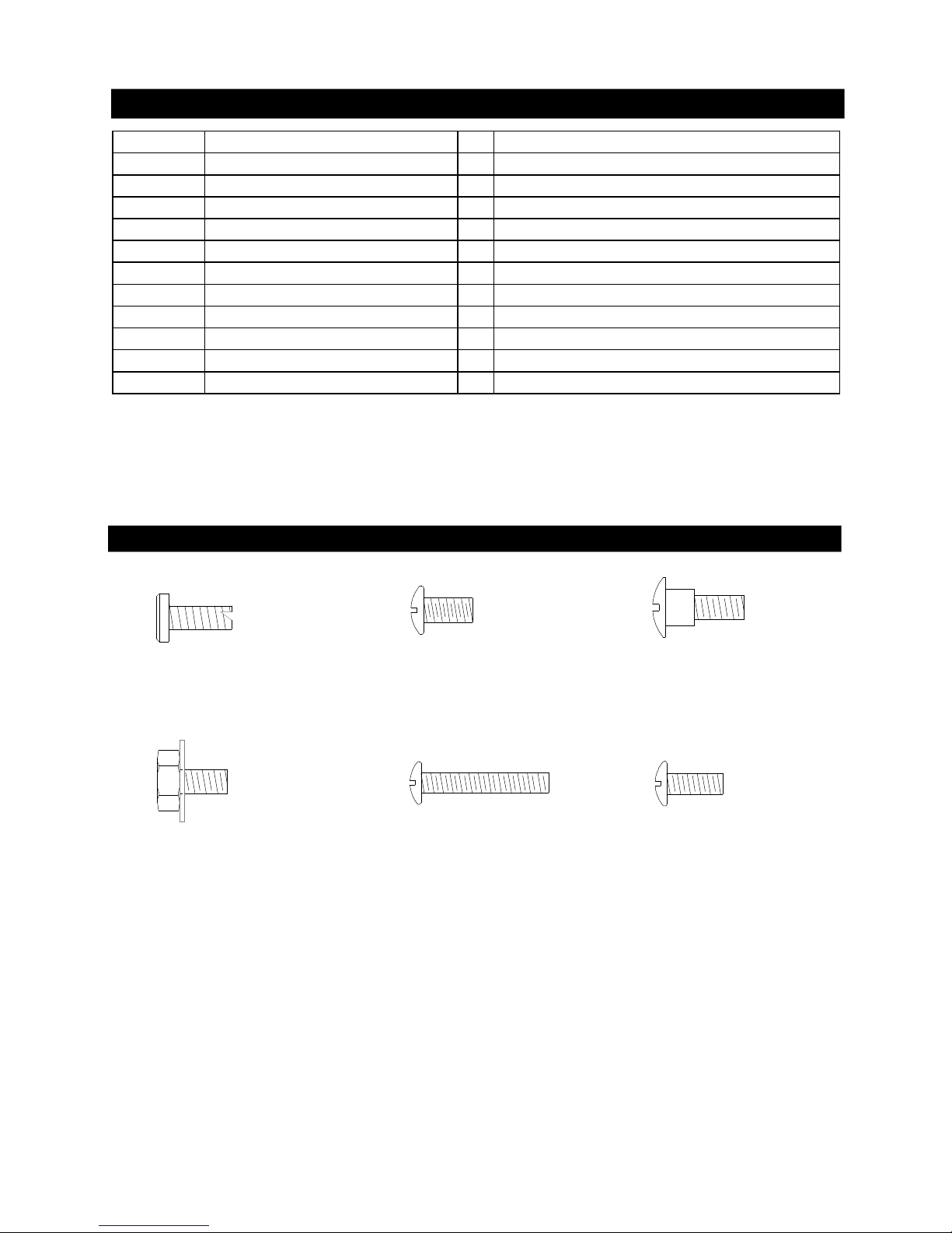
Hardware Diagram for Models IT2612ALP
Hex Head Screw 3/16"X3/8"
Qty. 8
Part # S162G03064
Phillips Head Screw 3/16"X3/8"
Qty. 13
Part # S112G03066
Phillips Head Screw 3/16"X1-3/16"
Qty. 4
Part # S112G0319A
Flat Head Self-tapping Screw
3/16"x3/8"
Qty. 4
Part # S152G0306D
Phillips Head Screw 3/16"X1/2"
Qty. 4
Part # S112G0308A
Phillips Head Bolt 3/16"x3/8"
Qty. 1
Part # S03110019A
PART # PART DESCRIPTION QTY PURPOSE OF PART
S152G0306DFlat Hand Self-tapping Screw 3/16" x 3/8"
4
Install Grill Head to Cart
S162G03064 Hex Head Screw 3/16" x 3/8"
6
Install Side Shelf to Cart
S162G03064 Hex Head Screw 3/16" x 3/8"
2
Install Side Shelf to Control Panel
S112G03066 Phillips Head Screw 3/16" x 3/8"
4
Install the Cart Bottom Shelf to Cart Side Panel Left/Right
S112G03066 Phillips Head Screw 3/16" x 3/8"
4
Install the Cart Front Panel to Cart Side Panel Left/Right
S112G0308A Phillips Head Screw 3/16" x 1/2" 4 Install Casters to Cart Left Frame
S112G03066 Phillips Head Screw 3/16" x 3/8"
3
Install the Cart Top Panel to Cart Side Panels
S03110019A Phillips Head Bolt 3/16" x 3/8" 1 Install Lighting Stick to Cart Left Side panel
S112G0319A Phillips Head Screw 3/16" x 1-3/16"
4
Install wheels to Cart Right Frame
S112G03066 Phillips Head Screw 3/16" x 3/8"
2
Install Tank Stop Plate to Cart Right Side Panel
Battery/AA 1
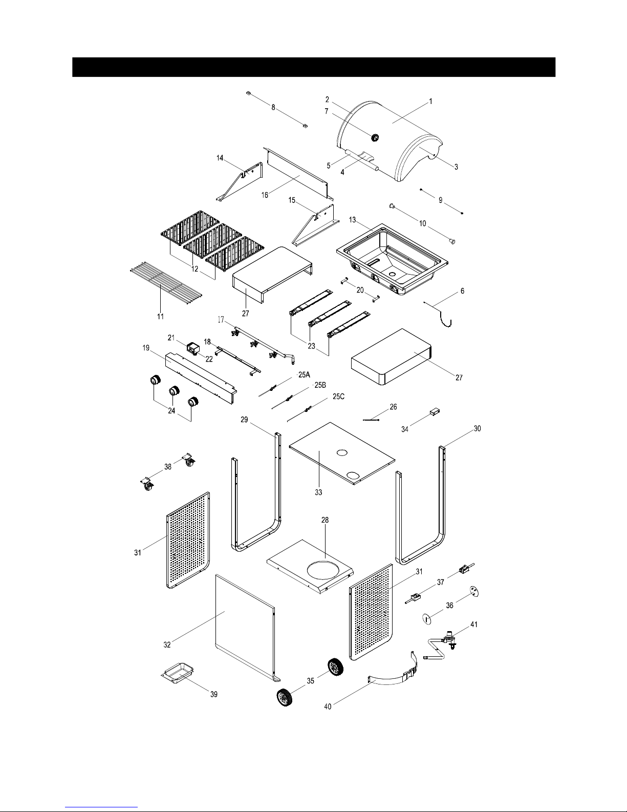
Parts Diagram for Models IT2612ALP
5

Parts List for Model IT2612ALP
6
KEY DESCRIPTION PART# QTY
1 Lid P00118519B 1
2 Lid Side Panel, Left P00105367K 1
3 Lid Side Panel, Right P00106367K 1
4 Lid Handle Bracket P00303191A 1
5 Lid Handle P00205111M 1
6 Lighting Stick P05507140M 1
7 Temperature Gauge P00601541A 1
8 Protective Pad, Rear P05518110S 2
9 Protective Pad, Front P05518111S 2
10 Lid Hinge P05501156B 2
11 Cooking Rack/Secondary P01504021E 1
12 Cooking Grid P01615057F 3
13 Bowl P007350192 1
14 Bowl Side Panel, Left P00761239A 1
15 Bowl Side Panel, Right P00762239A 1
16 Bowl Wind Shield P00716439A 1
17 Gas Valve/Manifold Assembly Y0060778 1
18 Gas Collector Tube - Cross Lighting Channel P022034384 1
19 Control Panel P02906597A 1
20 Control Panel Support Bracket P03303177K 2
21 Electric Ignitor, 4-Port P02502164C 1
22 Electric Ignitor Protector P03306164D 1
23 Main Burner P020030554 3
24 Main Control Knob P03443015W 3
25A Electric Wire Set, A P02618062C 1
25B Electric Wire Set, B P02618063C 1
25C Electric Wire Set, C P02618064C 1
26 Ground Wire P02628003H 1
27 Side Shelf, Left/Right P011050434 2
28 Cart Bottom Shelf P01001117D 1
29 Cart Frame, Left P033031652 1
30 Cart Frame, Right P033031662 1
31 Cart Panel, Left/Right P07510037B 2
32 Cart Panel, Front P077021292 1
33 Cart Panel, Top P01001116D 1
34 Tank Holding Plate P03303168D 1
35 Wheel P05123003A 2
36 Wheel Hup Cap P05124001C 2
37 Wheel Seat P03303169D 2
38 Caster 2" With Brake P05104010A 2
39 Grease Receptacle P02701305G 1
40 Tank Fastening Strap P05314016V 1
41 Regulator With Hose P03608001A 1
Operation Manual P80151130A 1
Assembly Instructions IT2612ALP
1
CAUTION : While it is possible for one person to assemble this grill, obtain assistance from another person
when handling some of the large, heavy pieces.
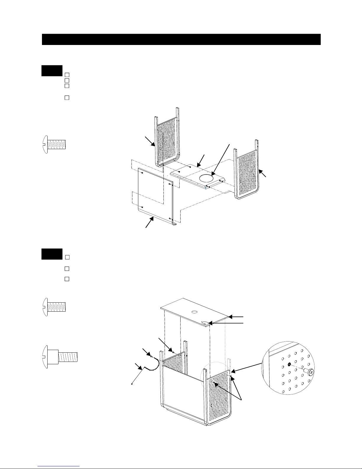
2
Place Cart Top Panel on top of the assembled Cart. Position the panel so that the hose hole is positioned to the
right front of Cart as shown.
Align the 4 holes on the edge of Cart Top Panel with the 4 holes on the 2nd hole(from both side) of the 2nd row
of Side Panels. See FIG. 1. Tighten 3 holes with 3 Phillips Head Screws 3/16"x3/8", except for the left front one.
Use a Phillips Head Bolt 3/16"x3/8" to attach the Lighting Stick and secure the hole as shown.
Install Cart Top Panel and Lighting Stick
Install Cart Side Panels, Bottom Shelf and Cart Front Panel
Remove all packaging materials.
Lay a piece of cardboard on the ground (refer to Pre-Assembly Instructions).
Attach Cart Side Panels onto the Cart Bottom Shelf, making sure that the hole in the panels are
aligned. Insert 4 Phillips Head Screws 3/16"x3/8" and tighten securely.
Attach the Cart Front Panel between the Cart Side Panels as shown; Align the 4 holes on the edge
of Cart Front Panel with the 4 holes in the front of Cart Side Panels. Insert 4 Phillips Head Screws
3/16"x3/8" and tighten securely.
Phillips Head Screw 3/16"x3/8"
Qty. 8
Part # S112G03066
Phillips Head Screw 3/16"x3/8"
Qty. 3
Part # S112G03066
Cart Front Panel
The tank hole located on
the right side.
(with fastening strap)
Left Side Panel
Right Side Panel
Bottom Shelf
Hose Hole
Cart Top Panel
Lighting Stick
2nd hole,
2nd row
Phillips Head Bolt 3/16"x3/8"
Qty. 1
Part # S03110019A
Bolt 3/16"x3/8"
Phillips Head
Screw 3/16"x3/8"
Phillips Head
Screw 3/16"x3/8"
7
FIG. 1
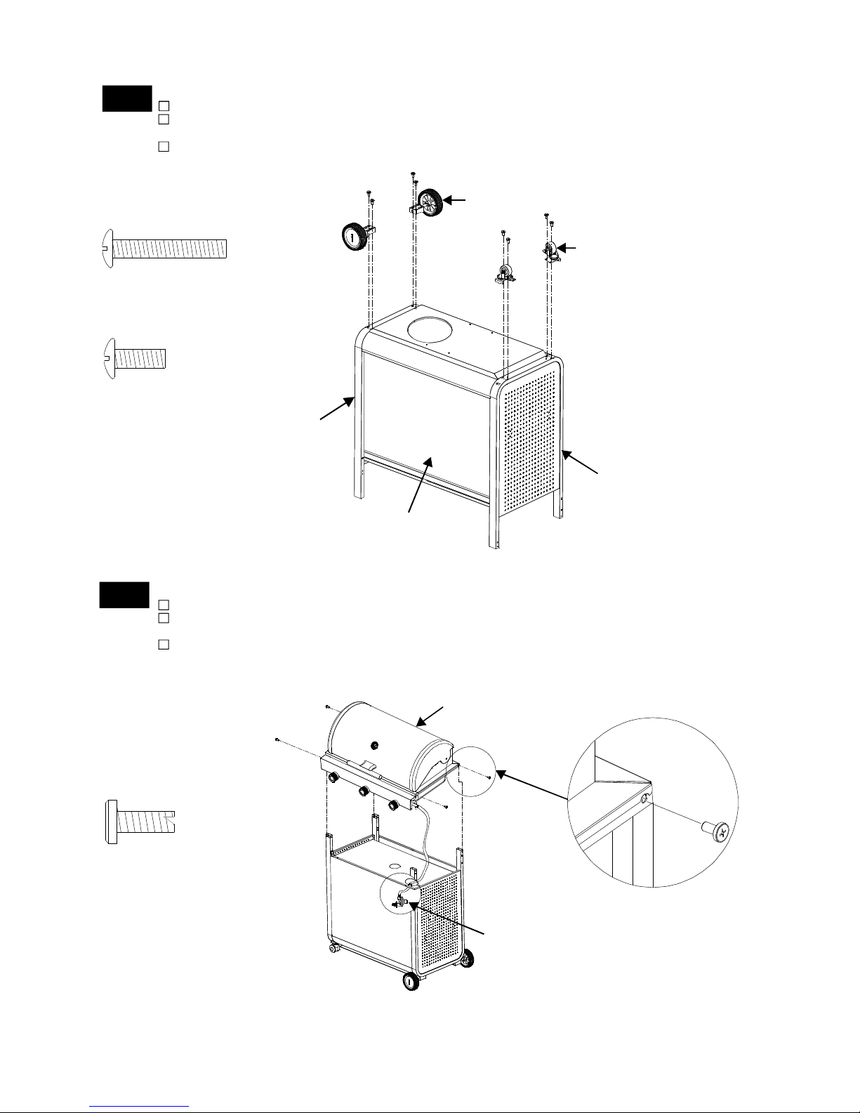
4
Install Grill Head
Remove all cooking components.
With the help of your assistant. Lift Grill Head and position it over the top of the Cart Frames.
Make sure that the LP regulator goes through the "O" shape in the right front of the Cart.
Align the 4 holes on the Bowl Frame Left/Right with the 4 holes on the top of Cart Frames.
Insert 4 Flat Head Self-tapping Screw 3/16" x 3/8", and tighten securely. See FIG.2.
Flat Head Self-tapping Screw
3/16" x 3/8"
Qty. 4
Part # S152G0306D
3
Position the Cart upside down as shown.
Attach two Casters to the Cart Left Frame; Align the four(4) holes on the Left Frame with the four(4) holes
on the Casters. Insert 4 Phillips Head Screws 3/16"X1-3/16" and tighten securely.
Attach two Wheels onto the Cart Right Frame; Align the 4 holes on the Wheel seats with the 4 holes on the
Right Frame. Insert 4 Phillips Head Screws 3/16"X1/2" and tighten securely as shown.
Install Casters and Wheels
Phillips Head Screw 3/16"X1-3/16"
Qty. 4
Part # S112G0319A
Phillips Head Screw 3/16"X1/2"
Qty. 4
Part # S112G0308A
Caster
Wheel
Left Frame
Cart Front Panel
Right Frame
FIG. 2
Regulator
Bowl Frame
Grill Head
8
 Loading...