

Page 1
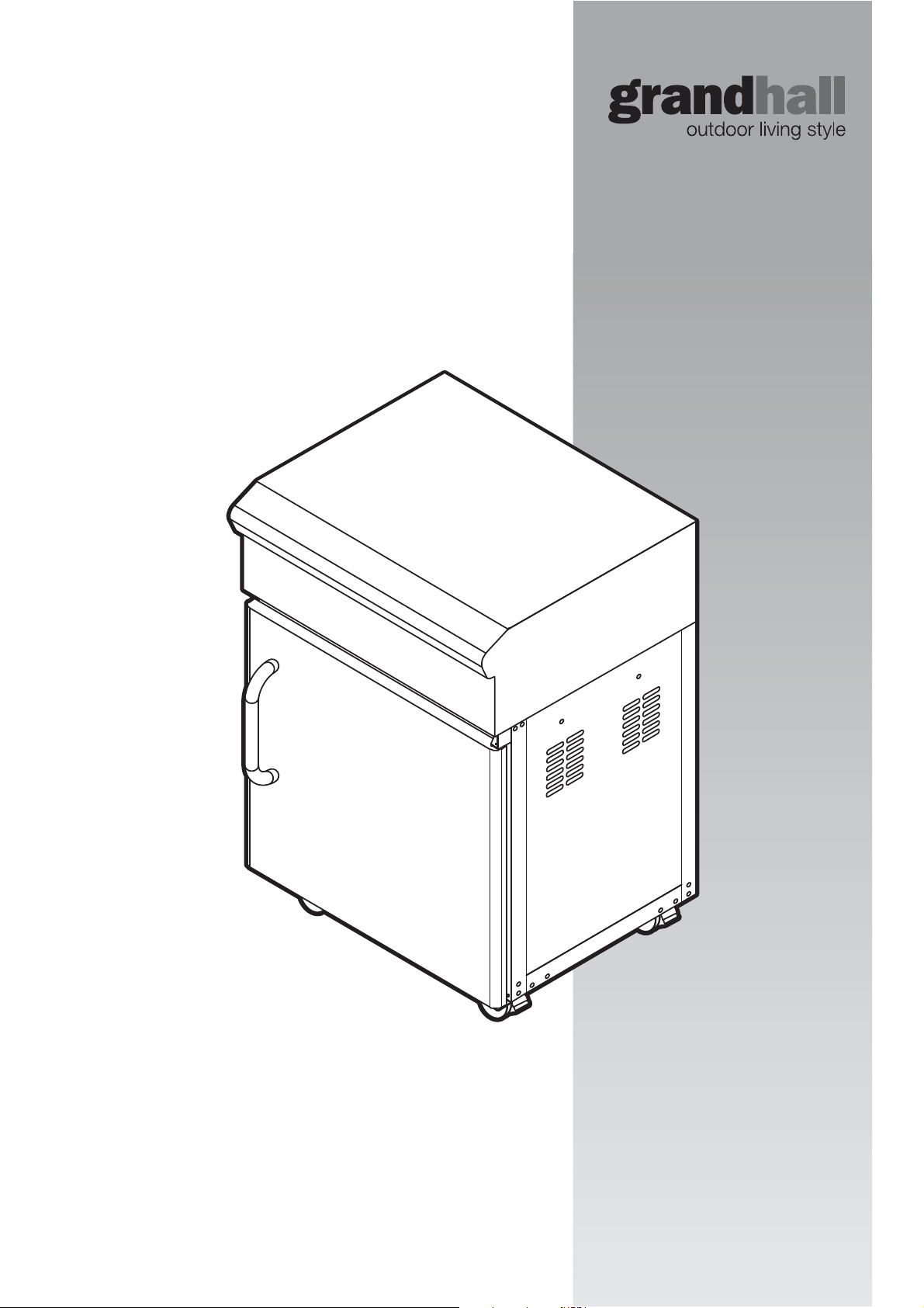
Assembly instructions
These instructions are a guide to assembling
the Premium Storage Module.
Please read carefully, and
retain for future reference
Illustration may vary from unit
contained in carton.
.
Page 2

2
GENERAL INFORMATION
2
TABLE OF CONTENTS
General Information 2
Pre-Assembly 2
Assembly 3-6
Maintenance 7
Parts Diagram/List 10-11
PRE-ASSEMBLY
GENERAL
FOR CUSTOMER REFERENCE
(Record and file in a safe place)
Purchased from
Date purchased
Serial No.
Sales docket must be kept as proof of purchase date.
NOTE:
TOOLS YOU WILL NEED
While it is possible for one person to assemble the
Module, we recommend asking for the assistance
of another person
Storage
when manoeuvring some of the larger and heavier pieces.
ASSEMBLY TIPS
1. Flatten cardboard packaging and use this as a protective
work surface to assemble upon.
2. Some protective coating may need to be removed from
components prior to assembly.
3. Unless specified otherwise, do not tighten screws and nuts
until trolley is fully assembled.
4. Pre-screwing of connection points for securing the side
shelves will assist in securing shelves smoothly.
CHECK FOR ANY DAMAGE
Before attempting to assemble this appliance, check that all the
necessary parts have been included using the parts list opposite.
Inspect parts as you proceed.
Contact your place of purchase for assistance regarding
replacement of any damaged or missing parts. Supplier contact
details are on the back cover of the instruction manual.
Do not assemble or operate an appliance that appears
damaged.
Standard Phillips-head screwdriver.
Adjustable spanner
(open end shifter).
CARTON CONTENTS
Description Qty
Trolley side panel – right 1
Trolley side panel – left 1
Trolley rear panel 1
Castors 4
Bottom shelf 1
Trolley bracket – front 1
Doors 1
Body assembly – head 1
Hardware pack 1
Page 3
3
LEFT
SIDE
RIGHT
SIDE
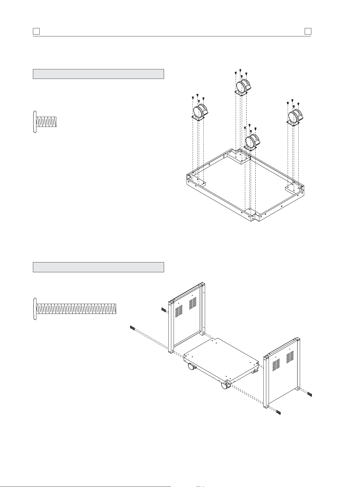
INSTALL CASTORS
• Place the trolley bottom shelf on the cardboard work surface
with the bottom side of shelf facing up. Install the four (4)
castors onto the castor seats as shown.
Phillips flat-head screw 1/4" x 1/2"
Qty. 16
ASSEMBLY
3
INSTALL TROLLEY LEGS WITH SIDE PANELS
• Install the left and right trolley legs with side panel (parts
are labelled ‘L’ or ‘R’)
Phillips flat-head screw
Qty. 8
to trolley bottom shelf.
1
/4" x 2"
Page 4
4
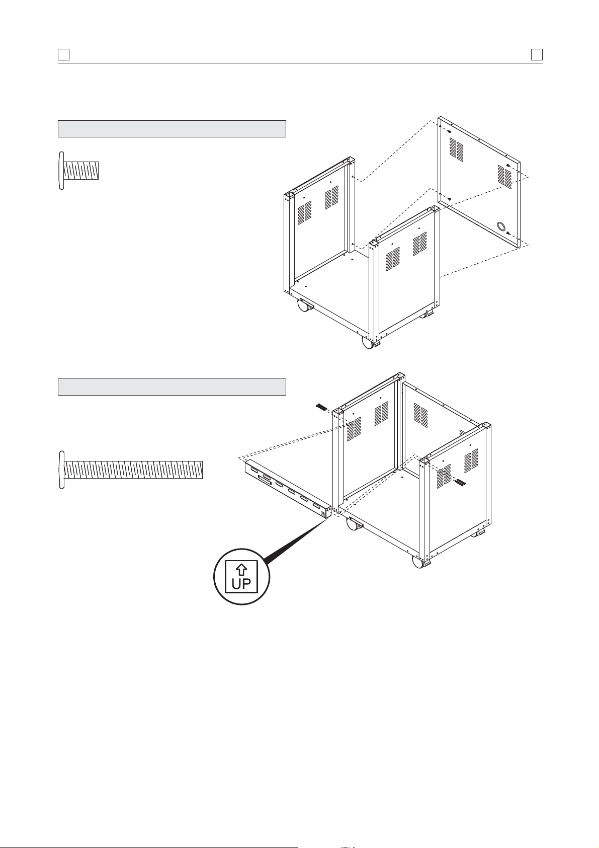
INSTALL TROLLEY REAR PANEL
Phillips flat-head screw 1/4" x 1/2"
Qty. 4
ASSEMBLY
4
INSTALL TROLLEY BRACKET
• Install the trolley bracket in the up position (part is labelled
‘UP’ to ensure proper assembly)
between front trolley legs
as shown.
Phillips flat-head screw
Qty. 4
1
/4" x 2"
Page 5
5
ASSEMBLY
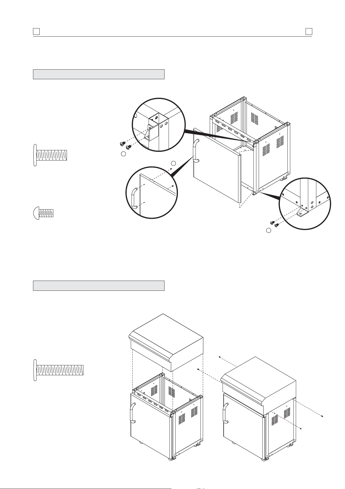
INSTALL DOOR
• Install the door handle to door.
• Install the bottom door hinge bracket to right
trolley leg.
• Insert door bottom post into bottom door
hinge bracket.
• Hold the door and install the top door
hinge bracket to right trolley leg.
B
Door handles
Phillips flat-head screw 1/4" x 3/4"
(Stainless steel) Qty. 2
5
A
Door hinges
Phillips-head screw
Qty. 4
3
/16" x 3/8"
INSTALL HEAD ASSEMBLY
• Tighten securely using screws.
Barbecue body to trolley
Phillips flat-head screw
Qty. 4
1
/4" x 13/16"
B
Page 6
6
ASSEMBLY
6
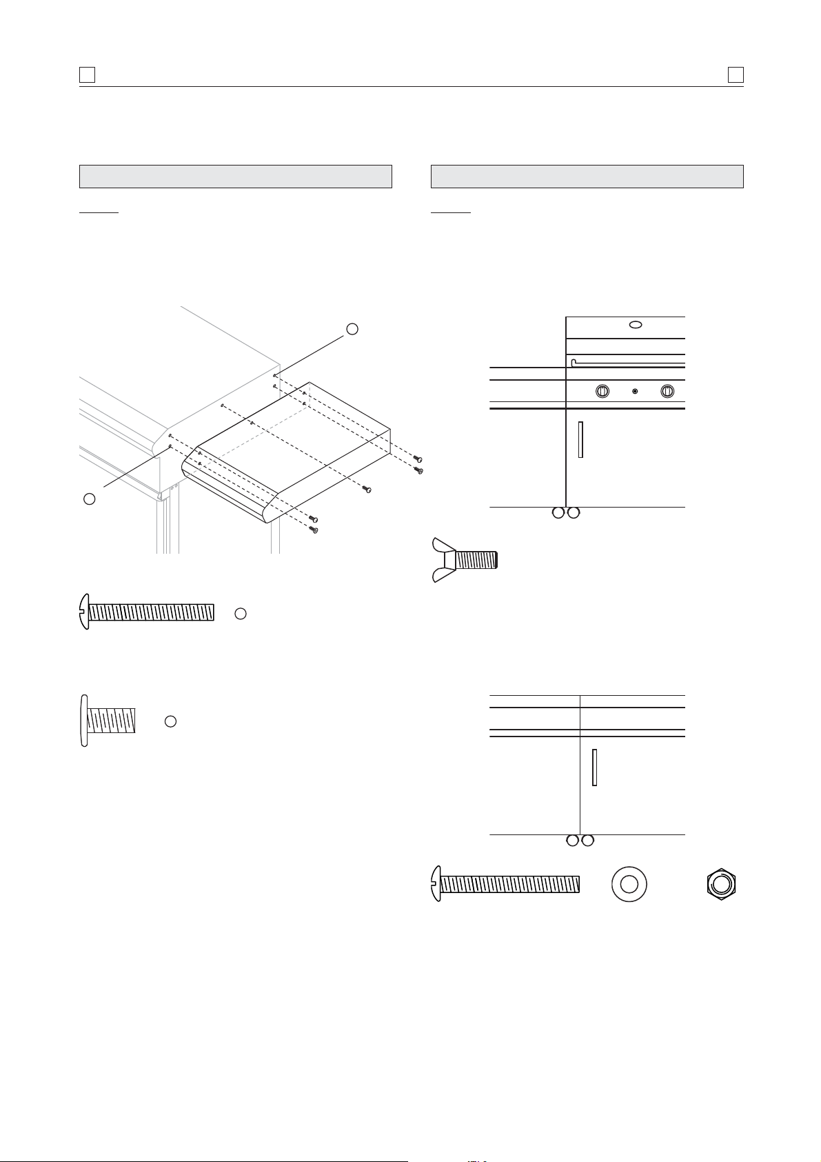
INSTALL SIDE SHELVES
NOTE: Shelves are not included, but are included
with the barbecue modules, and can be purchased
separately.
For information contact the place of purchase
or the manufacturer. Refer back page.
x 3
A
x 2
B
ATTACHING TO OTHER PREMIUM MODULES
NOTE: modules may be attached to both right and
left sides of the Barbecue, Range, and Sink /
Workstation modules.
1. To Barbecue Module
3
/16" x 11/4" Phillips-head screw
Qty. 3
B
1
/4" x 3/4" Phillips flat-head screw
Qty. 2 (supplied with barbecue)
1
/4" x 1/2" Wing-head screw
A
Qty. 3
2. To Range or Sink / Workstation Module
3
/16" x 11/2" Phillips-head screw
Qty. 2
3
/16" Flat washer
Qty. 4
3
/16" Nut
Qty. 2
Page 7
7
MAINTENANCE
7
DO NOT USE OVEN CLEANER TO CLEAN
THE OUTDOOR RANGE.
SOME PROPRIETORY BARBECUE
CLEANERS MAY AFFECT / DAMAGE
SOME OF THE SURFACE COATINGS
USED ON THIS APPLIANCE.
READ THE CLEANER INSTRUCTIONS
CAREFULLY.
IT IS RECOMMENDED TO TEST FIRST IN
AN INCONSPICUOUS PLACE.
GENERALLY WE RECOMMEND ONLY
WARM SOAPY WATER FOR CLEANING
THIS APPLIANCE.
IN COASTAL AREAS, FREQUENT
CLEANING AND THE USE OF A COVER
IS RECOMMENDED TO PROLONG THE
LIFE OF THE APPLIANCE.
SALTY AIR WILL ADVERSELY AFFECT
EXPOSED PARTS.
CLEANING AND MAINTENANCE
Proper care and maintenance will keep your Outdoor Range in top
operating condition and prolong its life. Follow these cleaning
procedures on a timely basis and your Outdoor Range will stay
clean and operate with minimum effort.
CLEANING EXTERIOR SURFACES
Before initial use and periodically thereafter we suggest you wash
your Outdoor Range using a mild soap and warm water solution.
You can use a wash cloth or sponge for this process. Do not use
a stiff wire or brass brush. These will scratch stainless steel and
chip painted surfaces
(varies by model) during the cleaning
process.
CARE FOR STAINLESS STEEL
Stainless steel over time will be affected by ‘tea staining’ (the
brown discolouration of some stainless steel)
.
Tea staining can be reduced by washing the surface with
mild detergent and warm water and then rinsing with clean cold
water. We recommend the surface be wiped dry with a clean
cloth.
STORAGE
We recommend that you minimise the exposure of the Outdoor
Range to the elements.
High moisture content in the air (rain, mist, salt spray etc.)
can affect metal components and lead to material breakdown. If
left in an area subjected to high moisture content, we strongly
recommend that you observe the cleaning procedure on a regular basis and cover the appliance whilst not in use.
Material breakdown from high moisture conditions can be
avoided if the appliance is well protected from the weather and
regular cleaning is performed.
Page 8
8
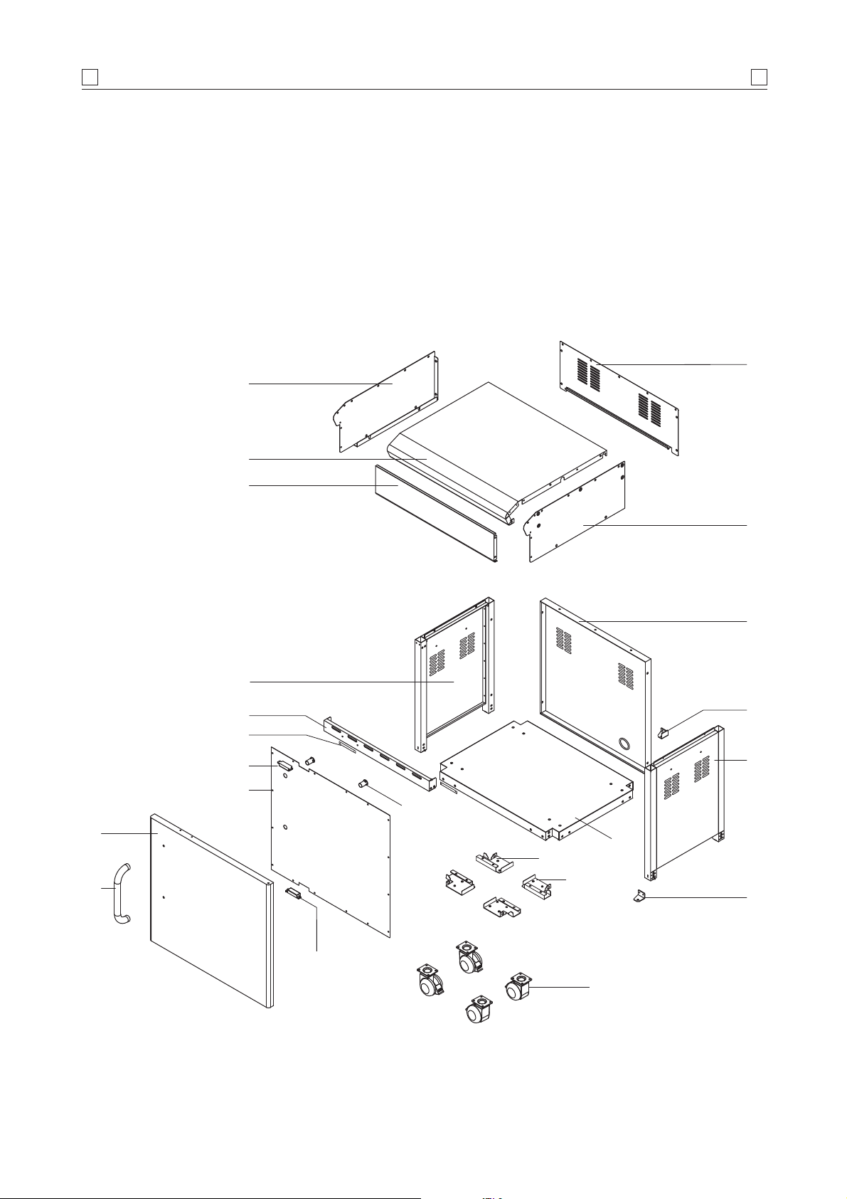
PARTS DIAGRAM
This diagram is provided to assist you identify
parts if replacement is necessary.
Contact the place of purchase or manufacture
to enquire about parts, availability and/or service.
Items included in Outdoor Range barbecue
specification may differ from parts list, depending
on region or specific dealer specification.
4
1
2
8
3
5
8
6
9
17
16
14
15
12
19
13
20
11
10
7
21
16
18
Page 9

9
PARTS LIST
9
Ref Description Part No. Qty
1 Head panel – top P01007006C 1
2 Front panel P02907781A 1
3 Bowl panel – rear P0072571IB 1
4 Bowl panel – left P00720715B 1
5 Bowl panel – right P00721715B 1
6 Trolley panel – left P07605013B 1
7 Trolley panel – right P07618013B 1
8 Trolley panel – rear P07702057A 1
9 Trolley bracket – front P03305015D 1
10 Door hinge – top right P03313002D 1
11 Trolley bottom shelf P01002052D 1
12 Door P04301019A 1
13 Door handle P00205029B 1
14 Door trim plate P07510002E 1
15 Door spacer P06801010G 2
16 Door magnet P05523002K 2
17 Door stop plate P05510002B 2
18 3" castor P05119001A 4
19 Castor seat – left rear, right front P05327008G 2
20 Castor seat – left front, right rear P05327007G 2
21 Door hinge – bottom right P03313003D 1
Hardware pack P06003076A 1
Page 10

101011
Page 11

11
Page 12

PRIVACY POLICY
Focus Lifestyle Products Pty Ltd may collect personal information
about a consumer of its products in the course of receiving or
responding to a warranty claim. Such information is only collected
to enable the resolution of the warranty claim to the consumer's
satisfaction, and is not disclosed to other organisations except
service agents or sometimes the applicable retailer.
Focus Lifestyle Products has a Privacy Policy
(which is
available on request), which encompasses compliance with the
Privacy Act 1988 (Cth). Importantly, individual consumers generally
have a right to access information held about them.
Manufactured by
Grand Hall Enterprises Ltd China
for
Focus Lifestyle Products Pty Ltd
ABN 93 160 136 977
223 - 225 Governor Road, Braeside,
Victoria, Australia 3195
P.O. Box 532 Mordialloc,
Victoria, Australia 3195
Tel: 1800 680 405
All specifications are subject to change
without notice.
PART NO . P80140161A Printed 10/2006
 Loading...