

Grand Hall Hgi08alp Owner's Manual
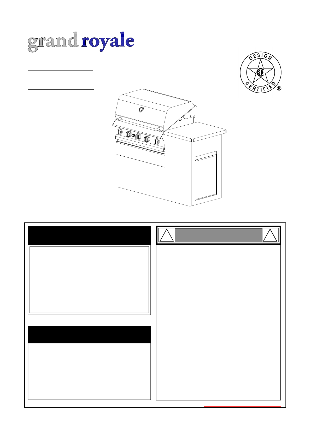
Liquid Propane Gas (LPG) Grill Island
Model HGI08ALP-1
Natural Gas (NG ) Grill Island
Model HGI08ANG-1
OPERATOR'S MANUAL
FREE HELP
FROM THE GRILL EXPERTS
Do not return to the store. At Grand Hall we're
the experts on this product and trained to help
you with:
Assembly questions
Ÿ
Grill operation
Ÿ
Replacement of damaged or missing parts
Ÿ
visit www.grandhall.com or call:
1-877-934-7455
Monday - Friday 8:00am-4:30pm CST
IMPORTANT:
NOTE TO ASSEMBLER / INSTALLER:
Ÿ
Leave this manual with the consumer.
NOTE TO CONSUMER:
Ÿ
Keep this manual for future reference.
RECORD YOUR SERIAL # __________________
Ÿ
(see silver CSA label on main body of grill)
! !
Ÿ
Ÿ
Ÿ
Ÿ
Ÿ
Ÿ
Ÿ
WARNING
Failure to comply with these instructions could
result in a fire or explosion that could cause
serious bodily injury, death or property damage.
Whether this grill was assembled by you or
someone else, you must read this entire manual
before using your grill to ensure the grill is
properly assembled, installed and maintained.
Use your grill at least 3 feet away from any
wall or surface. Use your grill at least 3 feet
away from combustible objects that can melt or
catch fire such as vinyl or wood siding, fences
and overhangs or sources of ignition including
pilot lights on water heaters and live electrical
appliances.
THIS GAS APPLIANCE IS DESIGNED FOR OUTDOOR USE ONLY.
Never use your gas grill in a garage, porch,
shed, breezeway or any other enclosed area.
Never obstruct the flow of ventilation air
around your gas grill housing.
Never disconnect the gas regulator or any gas
fitting while your grill is lit. A lit grill can ignite
leaking gas and cause a fire or explosion which
could result in property damage, personal injury
or death.
Manual # P80180001D - Date:2013/02/27
Table of Contents
Primary Safety Warnings...........................1-3
Pre-Assembly Instructions..............................3
Part Diagrams and Lists..........................4-8
Assembly Instructions...............................9-10
Use & Care Instructions:
• Gas Safety and Leak Tests............11-13
• Natural Gas Connection..........................14
• Lighting Instructions............................15-16
• Troubleshooting.........................................16
• Rotisserie Instruction...........................17-19
• Cleaning and Maintenance................20-21
• Cooking Guide...................................A1-A5
• Frequently Asked Questions............A6-A7
Warranty Terms............................Back Cover
!
DANGER
!
! !
•
•
•
WARNING
LPG models must be used with Liquid Propane
Gas and the regulator assembly supplied.
Natural Gas models must be used with Natural
Gas only. Any attempt to convert the grill from
one fuel type to another is extremely hazardous
and will void the warranty.
Keep gas regulator hose away from hot grill
surfaces and dripping grease. Avoid unnecessary twisting of hose. Visually inspect hose prior
to each use for cuts, cracks, excessive wear or
other damage. If the hose appears damaged do
not use the gas grill. Call Grand Hall at 1-877934-7455 for a certified replacement hose.
California Proposition 65
Combustion byproducts produced when using
this product contain chemicals known to the State
of California to cause cancer, birth defects, or other
reproductive harm.
If you smell gas:
1.
Shut off gas to the appliance.
Extinguish any open flame.
2.
3.
Open lid.
If odor continues, keep away from
4.
the appliance and immediately call
your gas supplier or your fire
department.
! !
1.
Do not store or use gasoline or other
WARNING
flammable liquids or vapors in the vicinity of this or any other appliances.
2.
An LP cylinder not connected for use
shall not be stored in the vicinity of
this or any other appliance.
Brass components on the grill, such as hose
fittings, propane cylinder valves (sold separately)
and burner valve stems, contain lead which is
known to the State of California to cause cancer,
birth defects, or other reproductive harm.
Never use charcoal or lighter fluid in this gas grill.
•
Failure to comply with these instructions could
result in a grease fire or explosion that could cause
serious bodily injury, death or property damage.
The Grease Tray must be visually inspected be-
•
fore each grill use. Remove any grease and wash
Grease Tray with a mild soap and warm water
solution. Failure to comply with these instruc-
tions could result in a grease fire or explosion
that could cause serious bodily injury, death or
property damage.
! !
This appliance, when installed, must be electri-
•
cally grounded in accordance with local codes
or, in the absence of local codes, with the
National Electrical Code, ANSI/NFPA 70, or the
Canadian Electrical Code, CSA C22.1.
Keep any electrical supply cord and the fuel
•
supply hose away from any heated surfaces.
WARNING
2
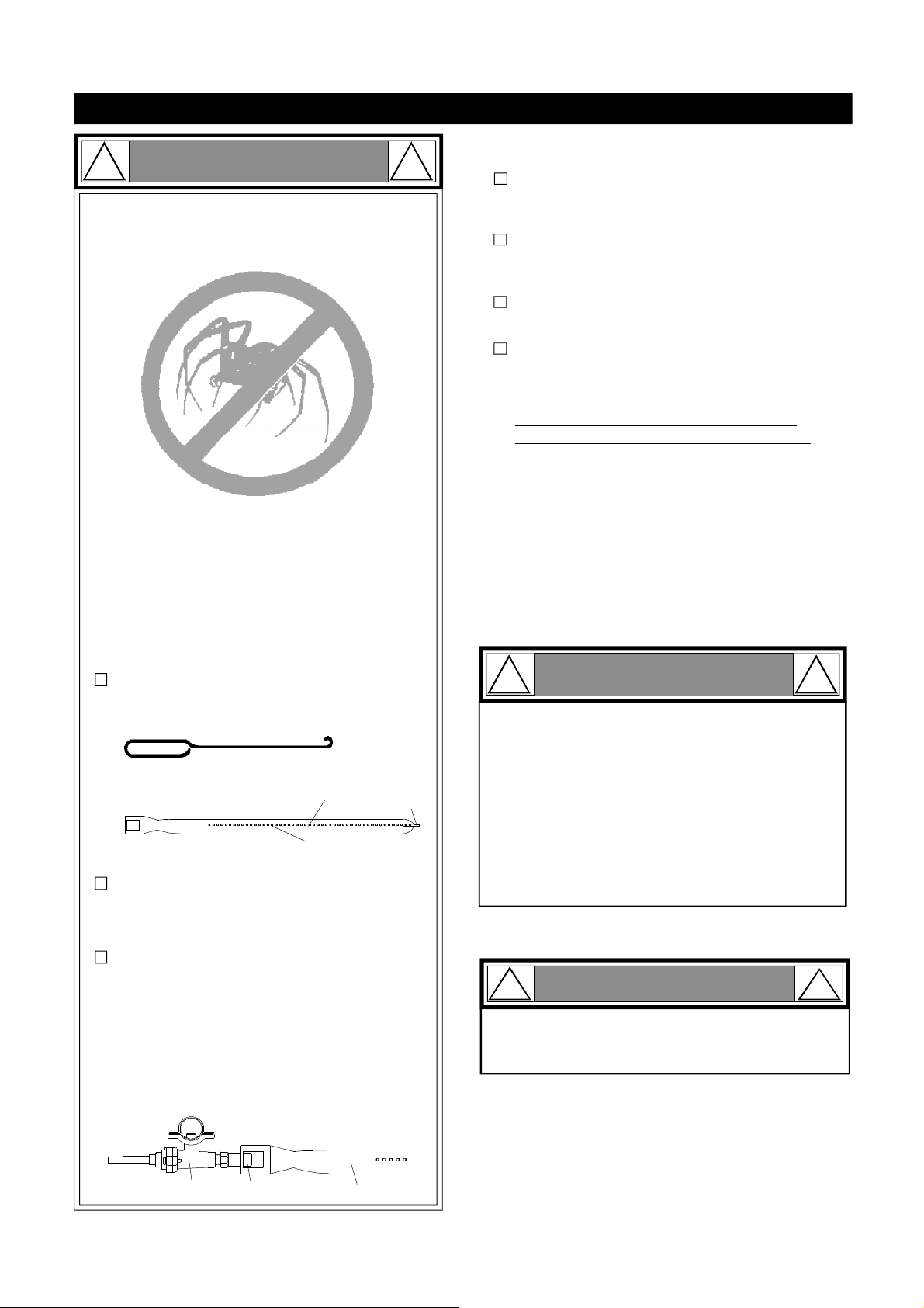
Pre-Assembly Instructions For Your Safety
! !
Failure to comply with these instructions may
result in a hazardous situation which, if not
avoided, may result in injury.
Spiders and small insects can spin webs and nest
in the grill Burner Tubes during transit and warehousing which can lead to a gas flow obstruction
resulting in a fire in and around the Burner Tubes.
This type of "FLASHBACK FIRE" can cause serious
grill damage and create an unsafe operating condition for the user.
To reduce the chance of FLASHBACK FIRE
you must clean the Burner Tubes as follows
before initial use. Also do this at least once a
month in summer and fall or whenever spiders are
active in your area, and if your grill has not been
used for an extended period of time.
Remove the screws from the rear of each Main
1.
Burner using a Phillips Head Screwdriver.
Carefully lift each Burner up and away from the Gas
2.
Valve Orifice.
Check and clean Burner/Venturi Tubes for insects
3.
and insect nests. A clogged tube can lead to a fire
beneath the grill.
Refer to the figure below and perform one of
4.
these 3 cleaning methods:
TO CLEAN BURNER TUBE,
INSERT HOOK
HERE
9
For safe operation ensure the Gas Valve Assembly
Orifice is inside the Burner Tube before using your
grill. See figure. If the Orifice is not inside the
Burner Tube, lighting the Burner may cause explosion and/or fire resulting in serious bodily injury
and/or property damage.
WARNING
METHOD 1: Bend a stiff wire or wire coat
hanger into a small hook as shown and run
the hook through the Burner Tube and inside
the Burner several times to remove debris.
Burner Port
Burner Tube
METHOD 2: Use a bottle brush with a flexible
handle and run the brush through the Burner
Tube and inside the Burner several times to
remove any debris.
METHOD 3: Use an air hose to force air through
each Burner Tube. The forced air should pass
debris or obstructions through the Burner and
out the Ports.
Foot
To expedite the assembly process follow these
general guidelines:
Tools Required for Assembly :
protective work gloves
•
•
Phillips Head Screwdriver
While it is possible for one person to unpack this gas
grill, obtain assistance from another person when
handling the large pieces.
Use the Hardware and Part Diagrams to ensure all
items are included and free of damage.
Do not assemble or operate the grill if it appears damaged. If there are damaged or missing parts when
you unpack the shipping box or you have questions
during the assembly process, call the:
Grill Information Center 1-877-934-7455
8am-4:30pm CST, Monday through Friday
Grill Installation Codes
The installation must conform with local codes or, in the
absence of local codes, with the National Fuel Gas Code,
ANSI Z223.1/NFPA 54, Storage and Handling of Liquefied Petroleum Gases, ANSI/NFPA58,Natural Gas and
Propane Installation Code, CSA B149.1, Propane Storage and Handling Code, B149.2.
! !
Do not store spare LP cylinder within
1.
WARNING
10 feet (3m) of this appliance.
Do not store or use gasoline or other
2.
flammable liquids and vapors within 25
feet (8m) of this appliance.
When cooking with oil/grease, do not
3.
allow the oil/grease to get hotter 350°F
(177°C)
4.
Do not leave oil/grease unattended.
!
When using electrical appliances, basic
safety precautions should always be used.
CAUTION
!
Orifice
Burner TubeGas Valve Assembly
3
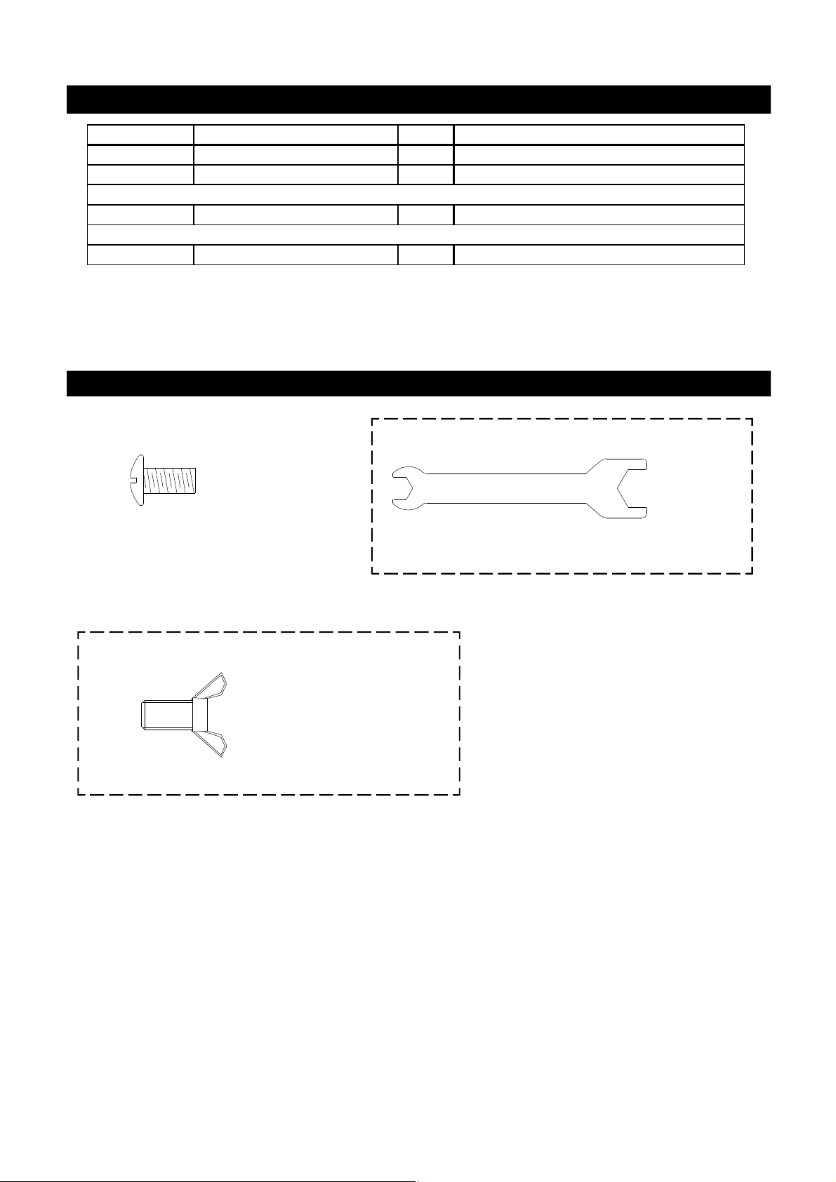
Hardware Pack Parts List for Model HGI08ALP-1 & HGI08ANG-1
PART # PART DESCRIPTION QTY PURPOSE OF PART
P06016003A Hardware Pack 1 For use in assembly (Gril)
S112G0406E Phillips Head Screw 1/4"x3/8" 4 Install Cart Frame to Grill Left Cart Legs
Already Installed on Tank Holder
S233G04084 Wing Bolt 1/4"x1/2" 2 Secures Gas Tank to Tank Holder
Already packed in the Cooking Components Box
P05515017L Wrench 1 Adjust level on Island Assembly Set
Hardware Pack Diagram for Model HGI08ALP-1 & HGI08ANG-1
Already packed in the Cooking Components Box
Phillips Head Screw 1/4"x3/8"
Qty. 4
Part # S112G0406E
Wrench
Qty.1
Part # P05515017L
Hardware already installed on the Tank Holder
Wing Bolt 1/4"x1/2"
Qty. 2
Part # S233G04084
* Two Batteries/AA included in the Hardware Pack.
4
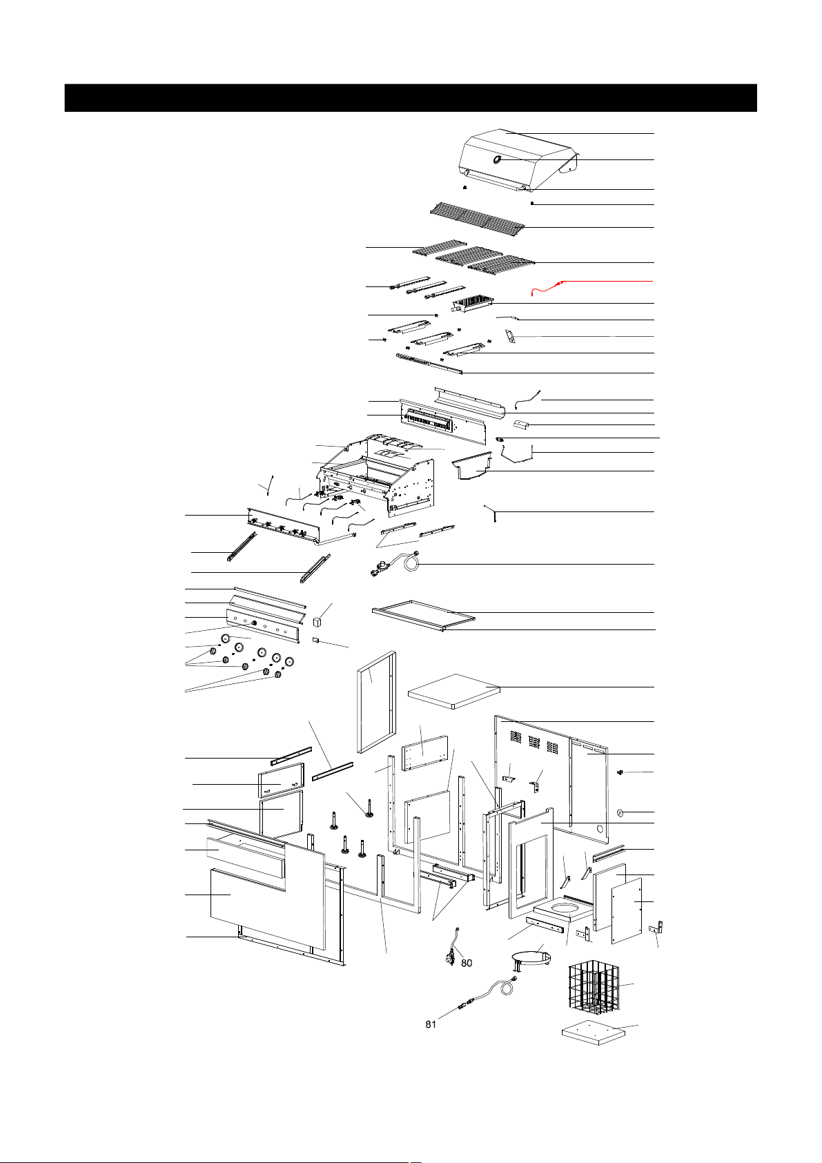
Parts Diagram for Model HGI08ALP-1 & HGI08ANG-1 Grill
1
2
3
4
5
7
6
8
65
64
82
9
10
19
11
12
24
38
72
27
28
29
69
32
30
49
73
40
57
31
63
34
18a
25
18
49
70
60
59
13
15
48
68
26
33
76
74
23
40
42
21
20
66
14
67
16
17
22
35
36
37
71
39
45
46
55
58
41
56
43
44
47
54
53
75
61
52
62
78
51
50
77
79
52b
52a
5

Parts List for Model HGI08ALP-1 & HGI08ANG-1 Grill
KEY DESCRIPTION PART # QTY
1 Lid Assembly P001474134 1
Temperature Gauge P00601297A 1
2
Lid Handle P00205069M 1
3
4 Protective Pad P05518011 I 2
5 Cooking Rack/Secondary P01516004J 1
6 Cooking Grid 13" P01604013B 2
7 Cooking Grid 6.5" P01604031B 1
8 Burner P020080324 3
9 Infrared Burner Assembly P020050104 1
10 Thermocouple P05305019A 1
11
12 Burner Bracket P0220342DD 1
13 Rotisserie Burner Assembly P02007068A 1
14 Rotisserie Burner Wind Shield P06906046B 1
15 Rotisserie Burner Electrode P02614025A 1
16
17 Rotisserie Burner Extension Tube P03717045B 1
18 Bowl P0071334P4 1
18a Bowl Wind Shield P069060754 1
19
20
21
22 Burner Heat Shield P07523003P 1
23 Grease Tray Heat Shield P069040204 1
24
25 Electric Wire Set P02615103A 1
26 Gas Collector Box with Electrode P02609010B 3
27 Control Panel Extension P0290976HS 1
28 Control Panel, Upper/Grill
29 Control Panel/Grill P0290978FA 1
30 Control Knob P03411503L 3
31 Control Knob For Back Burner/Infrared Burner P03411513L 2
32 Control Knob Spring P05504021A 5
33
34 Control Knob Seat P03415014S 5
35 Lighting Stick Assembly P05507008A 1
36 Regulator with Hose (LPG) P03601004A 1
37 Grease Tray/Grill P02717454A 1
38 Bowl Support Bracket, Left P01301007K 1
39
40 Cart Panel, Lower/Left & Middle
41 Cart Panel, Right
42 Cart Frame, Right/Grill
43 Cart Panel, Front/Grill
44 Cart Frame for Front Panel/Grill
45 Cart Panel, Rear/Left/Grill
46 Cart Panel, Rear/Right/Grill
47
48
49
50
Savor Plate
Rotisserie Burner Orifice (LPG) P06534005A 1
Rotisserie Burner Orifice (NG) P06534009A 1
Thermocouple Bracket
Cart Panel Bracket A
Cart Panel Bracket B
Gas Valve/Manifold Assembly/Grill (LPG) Y0060412 1
Gas Valve/Manifold Assembly/Grill (NG) Y0060663 1
Cart Frame, Left/Grill P01303016B 1
Cart Panel, Top
Cart Frame, Front/Grill P00907003C 1
Cart Frame, Rear/Grill
Drawer Slide Set P05516012C 1
Door P04301030J 1
®
P017080074 3
P03343008C
P03327038C
P03327039C
P0290977FS
P07801027A
P07604016B 2
P07620001D 1
P03344007D 1
P07621004D 1
P03344003D 1
P07702082M 1
P07702083M 1
P00907004C
1
1
1
1
1
1
6
Parts List for Model HGI08ALP-1 & HGI08ANG-1 Grill
KEY DESCRIPTION PART # QTY
51
52
52a Cart Basket Bottom (NG) P01001053D 1
52b Cart Basket (NG) P05203007G 1
53
54
55
56
57
58
59
60
61
62
63 Electric Wire/Grill P02616011D 1
64 Savor Plate Bracket, Front P033280504 3
65 Savor Plate Bracket, Rear P033280514 3
66 Back Burner Thermocouple P05305022A 1
67 Back Burner Thermocouple Bracket P033280474 1
68
69 Electric Ignitor, 6-port P02502075C 1
70 Electric Ignitor Protector P05545002A 1
71 Grease Tray Handle/Grill P00213012M 1
72 Bowl Support Bracket, Right P01302007K 1
73 Cart Panel, Upper/Left
74 Cart Panel, Upper/Middle
75
76
77
78
79
80
81
82
Door Handle P00215031A 1
Tank Tray (LPG) P04009030B 1
Slide Set P05516013C 1
Slide Bracket A P03311011D 2
Hose Holder (LPG)
Drawer P01901008I 1
Drawer Handle P00215032A 1
Protective Cap A P05535008I 1
Name Plate P00407031T 1
Level Adjuster P05322004A 4
Door Bracket, Left P033020274 1
Door Bracket, Right P033020284 1
Grease Draining Plate
Tank Holder (LPG) P05358002Y 1
Grease Tray Heat Shield, Lower
Door Trim Panel
L Bracket, Left
L Bracket, Right
NG Regulator
Hose, 12FT/NG
Infrared Burner Electrode
Cover/Grill
Cover/Range
Rotisserie Assembly Y0250152 1
Hardware Pack P06016003A 1
Operator's Manual/Grill P80180001D 1
P055360014
P069020094
P01304009D 1
P01305009D 1
P06903050M
P07510023H
P033020314
P033020324
Y0080023
P03703001A
P02614057A
P07002064B
P07002065B
1
2
1
1
1
1
1
1
1
1
1
To Order Grand Hall Certified Replacement Parts, Call 1-877-934-7455
To obtain the correct replacement parts for your grill, please refer to the part numbers in this parts list.
The following information is required to ensure you receive the correct parts:
1. Model and Serial Number (see CSA label on grill)
2. Part Number
3. Part Description
4. Quantity of parts needed
Important: Use only Grand Hall certified replacement parts. The use of any part that is not a factory
authorized part can be dangerous and will also void your product warranty. Keep this Operator's Manual
for convenient referral and for part replacement.
7
Y0250152 Rotisserie Assembly Parts Diagram
2
5
2
KEY
1.
2.
3.
4.
5.
6.
7.
8.
9.
10.
8
Y0250152 Rotisserie Assembly Parts List
DESCRIPTION
1.
Rot. Bushing
2.
Rot. Thumbscrew 1/4"x1/2"
3.
Rot. Collar
4.
Rot. Spit
5.
Rot. Holding Fork
6.
Rot. Motor Bracket
7.
Rot. Motor/AC
8.
Rot. Screw#10-24x3/4"UNC
9.
Rot. Washer
Rot. Nut #10-24
7
4
2
1
6
3
9
10
PART#
P05508092F
S196G04084
P05508091F
P05508175F
P05508090F
P05508174F
P07101048A
S112G10124
S411G03084
S362G10124
QTY
1
3
1
1
2
1
1
2
2
2
Hardware for Rotisserie
Rot. Thumbscrew
1/4"x1/2"
Qty. 3
Part # S196G04084
Grill Information Center: If you have questions about assembly or grill operation, or if there are damaged
or missing parts when you unpack this unit from the shipping box, call us 8:00 am - 4:30 pm CST, Monday
through Friday at: 1-877-934-7455
Rot. Screw#10-24x3/4"
UNC
Qty. 2
Part # S112G10124
Rot.Washer
Qty. 2
Part # S411G03084
Rot. Nut.#10-24
Qty. 2
Part # S362G10124
8

1
Phillips Head Screw
1/4"x3/8"
Qty.4
Part # S112G0406E
Install Cart Frame
Align the 4 holes in the Cart Frame and the
Cart Frame, Left/Grill. Insert the 4 Phillips
Head Screws 1/4"x3/8" and tighten securely.
Assembly Instructions
3
Install Ignitor Battery
Unscrew Ignitor Cap from Control Panel.
Place supplied AA battery into the Ignitor Slot
with positive pole facing you.
Position the Cap and Spring over the AA
battery and tighten onto Control Panel.
2
! !
Connect the 12' Natural Gas Hose
Connect the Swivel nut of the 12' Natural Gas
Hose to the Inlet fitting of NG Regulator as
shown. Connect the other end of the hose
to the gas supply line.
Gas Inlet
CAUTION
AA Battery
Ignitor Cap
4
NG Hose
Inlet Fitting
Swivel Nut
12' Natural Gas Hose
Ignitor Slot
Spring
With the assistance of another person,
perform this Electrode Check before
proceeding.
This test will ensure that the Spark Electrode Tips
are properly positioned so your grill lights easily
and properly.
Be sure all Control Knobs are set to "OFF"
and open the Grill Lid.
Have your assistant stand behind to the
right of the grill and look toward the front of
the grill bowl. Never put your face inside the
Grill Head.
Press the Ignitor Cap. You should hear a
"clicking" sound. Your assistant should see
a blue spark within each Gas Collector Box.
If a spark is present the Electrode Tips are
properly positioned.
If no spark is seen, the Spark Gap needs
to be adjusted as follows:
If the gap between the Spark Electrode
•
Tip and Receiver is more than 3/16" wide
use long nose pliers to gently squeeze
the Gas Collector Box to narrow gap.
•
Recheck the Electrode again, if no "clicking"
sound is heard:
-
AA Battery may be installed backwards.
Electric wires may be loose. Remove
-
the AA Battery and inspect the Ignitor
Junction Box found behind the Control
Panel and reconnect any loose wires.
Use your grill at least 3 feet away from
any wall or surface.
Do not obstruct the flow of air for combustion
and ventilation.
! !
CAUTION
Keep the ventilation openings of the Tank
Tray cabinet free and clear of debris.
Spark Gap
Gas Collector Box
Spark Electrode Tip
Spark Receiver
9
 Loading...