

Grand Hall Gt3211ang, Gt2411ang, Gt2411alp, Gt3211alp Owner's Manual
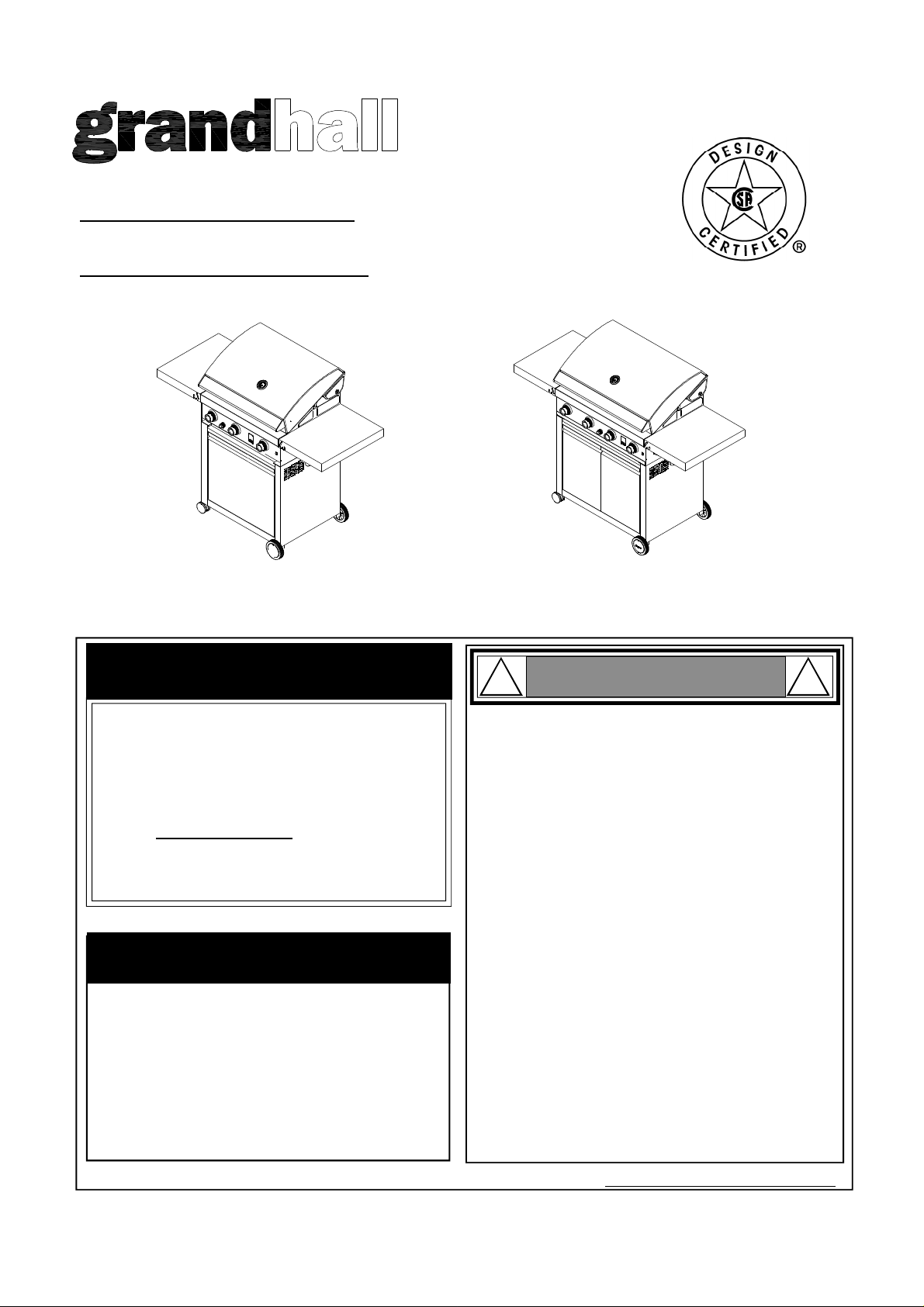
Liquid Propane Gas (LPG) Grill
Models GT2411ALP, GT3211ALP
Natural Gas (NG ) Grill
Models GT2411ANG, GT3211ANG
Operator's Manual
GT2411ALP/NG
FREE HELP
FROM THE GRILL EXPERTS
Grand Hall is the expert on this product and
trained to help you with:
Assembly Questions
Ÿ
Grill Operation
Ÿ
Replacement of Damaged or Missing parts
Ÿ
visit www.grandhall.com or call:
1-877-934-7455
Monday - Friday 8:00am-4:30pm CST
IMPORTANT:
NOTE TO ASSEMBLER / INSTALLER:
Ÿ
Leave this manual with the consumer.
Ÿ
NOTE TO CONSUMER:
Keep this manual for future reference.
Ÿ
RECORD YOUR SERIAL #
__________________
(see silver CSA label on main body of grill)
GT3211ALP/NG
! !
Failure to comply with these instructions could result
Ÿ
in a fire or explosion that could cause serious bodily
injury, death or property damage.
Whether this grill was assembled by you or someone
Ÿ
else, you must read this entire manual before using
your grill to ensure the grill is properly assembled,
installed and maintained.
Use your grill at least 3 feet away from any wall
Ÿ
or surface. Use your grill at least 3 feet away from
combustible objects that can melt or catch fire such
as vinyl or wood siding, fences and overhangs or
sources of ignition including pilot lights on water
heaters and live electrical appliances.
THIS GAS APPLIANCE IS DESIGNED FOR OUT-
Ÿ
DOOR USE ONLY.
Never use your gas grill in a garage, porch, shed,
Ÿ
breezeway or any other enclosed area.
Never obstruct the flow of ventilation air
Ÿ
around your gas grill housing.
Never disconnect the gas regulator or any gas fitting
Ÿ
while your grill is lit. A lit grill can ignite leaking gas
and cause a fire or explosion which could result in
property damage, personal injury or death.
WARNING
Manual # P80134013A - Date:2011/01/20
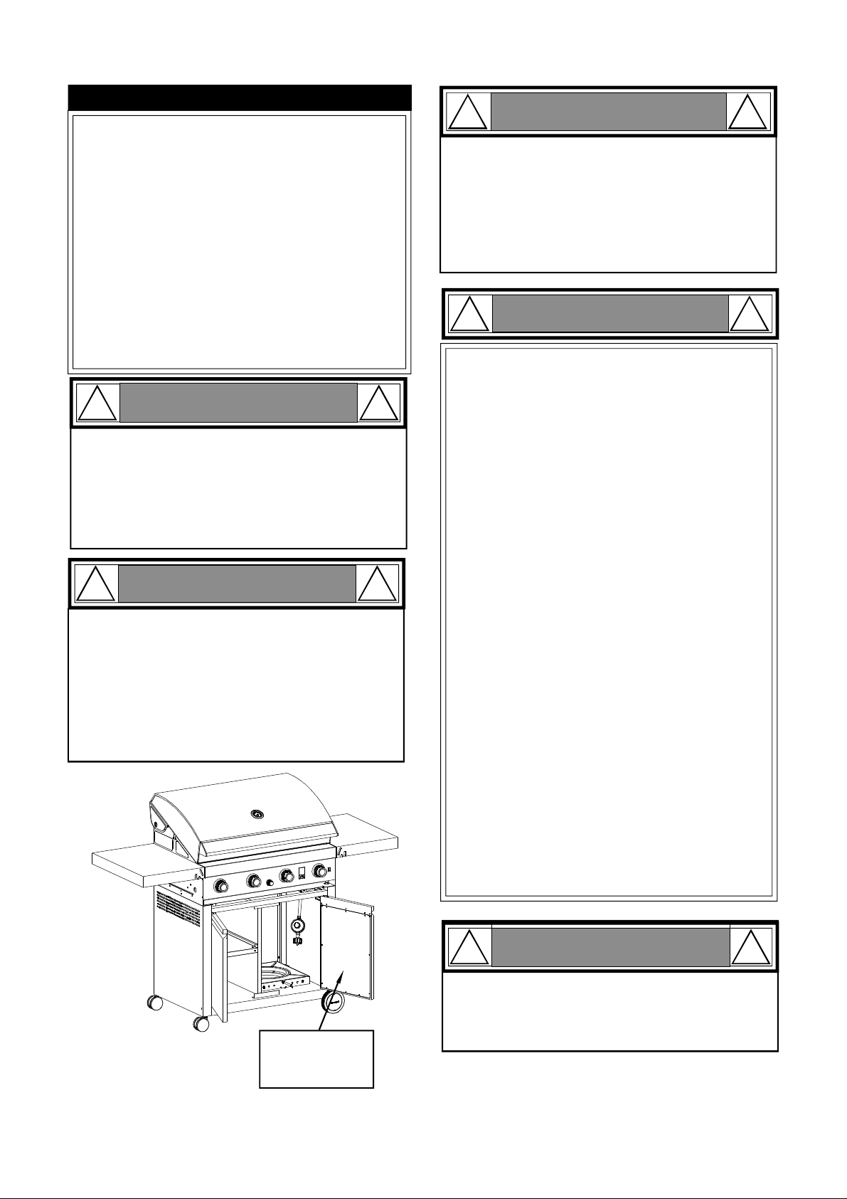
Table of Contents
Primary Safety Warnings..............................1-3
Pre-Assembly Instructions................................3
Parts Diagram and Lists............................4-13
Assembly Instructions..................................14-22
Use & Care Instructions:
• Gas Safety and Leak Tests................23-25
• Natural Gas Connection............................26
• Lighting & Fuel Gauge Instructions....27-28
• Troubleshooting............................................29
• Transformer Instructions.............................30
Cleaning and Maintenance.......................31-32
Cooking Guide..........................................A1-A4
Frequently Asked Questions..................A5-A6
Warranty Terms.................................Back Cover
!
•
This appliance, when installed, must be electrically grounded in accordance with local codes
or, in the absence of local codes, with the
National Electrical Code, ANSI/NFPA 70, or the
Canadian Electrical Code, CSA C22.1.
•
Keep any electrical supply cord and the fuel
supply hose away from any heated surfaces.
!
If you smell gas:
Shut off gas to the appliance.
1.
2.
Extinguish any open flame.
Open lid.
3.
If odor continues, keep away from
4.
the appliance and immediately call
your gas supplier or your fire
department.
WARNING
DANGER
!
!
! !
1.
Do not store or use gasoline or other
WARNING
flammable liquids or vapors in the
vicinity of this or any other appliances.
An LP cylinder not connected for
2.
use shall not be stored in the vicinity
of this or any other appliance.
! !
LPG models must be used with Liquid Propane
•
Gas and the regulator assembly supplied. Natural
Gas models must be used with Natural Gas only.
Any attempt to convert the grill from one fuel type
to another is extremely hazardous and will void the
warranty.
Keep gas regulator hose away from hot grill surfaces
•
and dripping grease. Avoid unnecessary twisting of
hose. Visually inspect hose prior to each use for cuts,
cracks, excessive wear or other damage. If the hose
appears damaged do not use the gas grill. Call 1877-934-7455 for a certified replacement hose.
California Proposition 65
•
Combustion byproducts produced when using this
product contain chemicals known to the State of California to cause cancer, birth defects, or other reproductive
harm.
Brass components on the grill, such as hose fittings,
•
propane cylinder valves (sold separately) and burner
valve stems, contain lead which is known to the State of
California to cause cancer, birth defects, or other reproductive harm.
Never use charcoal or lighter fluid in this gas grill.
•
Failure to comply with these instructions could result in
a grease fire or explosion that could cause serious
bodily injury, death or property damage.
WARNING
CSA Label
located on the
right door panel
The Grease Tray must be visually inspected before each
•
grill use. Remove any grease and wash Grease Tray
with a mild soap and warm water solution. Failure to
comply with these instructions could result in a grease
fire or explosion that could cause serious bodily injury,
death or property damage.
! !
Never cover or wrap the Cooking Grids, bottom of
the Grill Bowl, or Grease Tray with aluminum foil
or any other material that will absorb grease.
2
WARNING
Pre-Assembly Instructions For Your Safety
! !
Failure to comply with these instructions may result
in a hazardous situation which, if not avoided, may
result in injury.
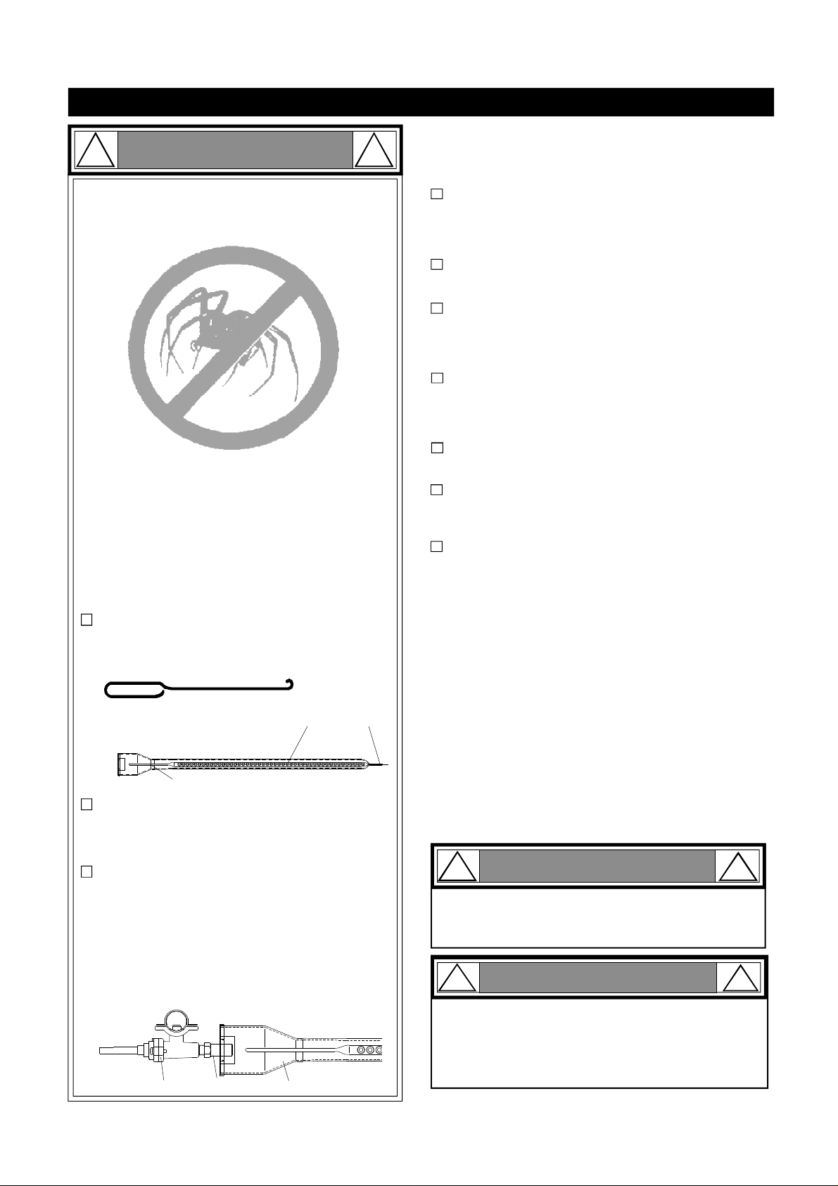
Spiders and small insects can spin webs and nest
in the grill Burner Tubes during transit and warehousing which can lead to a gas flow obstruction
resulting in a fire in and around the Burner Tubes.
This type of "FLASHBACK FIRE" can cause serious
grill damage and create an unsafe operating condition for the user.
To reduce the chance of FLASHBACK FIRE
you must clean the Burner Tubes as follows
before initial use. Also do this at least once a
month in summer and fall or whenever spiders are
active in your area, and if your grill has not been
used for an extended period of time.
CAUTION
PRE-ASSEMBLY
Read and perform the following pre-assembly instructions:
Tools Required for Assembly:
protective work gloves
•
protective eyewear
•
Phillips Head Screwdriver
•
You will need assistance from another person to handle
the grill head and other large, heavy parts.
Open lid of shipping carton. Remove top sheet of
cardboard and packing materials. Lay cardboard sheet
on floor and use as a work surface to protect floor and
grill parts from scratches.
You may slice the carton front corners with a utility knife
to lay open the carton front panel. This allows you to
raise the Lid and remove the components packed inside, making it easier to lift.
Remove the screws from the rear of each Main Burner
1.
using a Phillips Head Screwdriver or wrench.
Carefully lift each Burner up and away from the Gas
2.
Valve Orifice.
Check and clean Burner/Venturi Tubes for insects
3.
and insect nests. A clogged tube can lead to a fire
beneath the grill.
Refer to the figure below and perform one of these
4.
3 cleaning methods:
METHOD 1: Bend a stiff wire or wire coat hanger
into a small hook as shown and run the hook
through the Burner Tube and inside the Burner
several times to remove debris.
TO CLEAN BURNER TUBE,
INSERT HOOK
HERE
9
METHOD 2: Use a bottle brush with a flexible
handle and run the brush through the Burner
Tube and inside the Burner several times to
remove any debris.
METHOD 3: Use an air hose to force air through
each Burner Tube. The forced air should pass
debris or obstructions through the Burner and out
the Ports.
For safe operation ensure the Gas Valve Assembly Orifice is inside the Burner Tube before using
your grill. See figure. If the Orifice is not inside
the Burner Tube, lighting the Burner may cause
explosion and/or fire resulting in serious bodily
injury and/or property damage.
Burner Tube
Burner Port
Foot
Use the Hardware and Part Diagrams to ensure all items
are included and free of damage.
Do not throw away the bags of hardware that are included with boxed parts. These are required for assembly.
Do not assemble or operate the grill if it appears damaged. If there are damaged or missing parts when you
unpack the shipping box or you have questions during
the assembly process call
1-877-934-7455 M-F 8AM-4:30PM CST for assistance.
Grill Installation Codes
The installation must conform with local codes or, in the
absence of local codes, with either the National Fuel Gas
Code, ANSI Z223.1/NFPA 54, Natural Gas and Propance
Installation Code, CSA B149.1, or Propane Storage and
Handling Code, B149.2.
WARNING: Grease can get very hot. Always handle the Grease
Tray with a flame retardant BBQ mitt. Before removing the
Tray, always be sure that the grill has properly cooled. Be
aware that the tray does contain grease and be extremely
careful when removing the tray to prevent spillage. Failure to
follow these instructions could cause serious bodily injury or
property damage.
!
When using electrical appliances, basic safety
precautions should always be used.
!
To reduce the chance of FLASHBACK FIRE you must clean
the Burner Tubes at least once a month in summer and
fall or whenever spiders are active in your area, and if your
grill has not been used for an extended period of time.
CAUTION
WARNING
CAUTION
!
!
Orifice
Burner TubeGas Valve Assembly
3
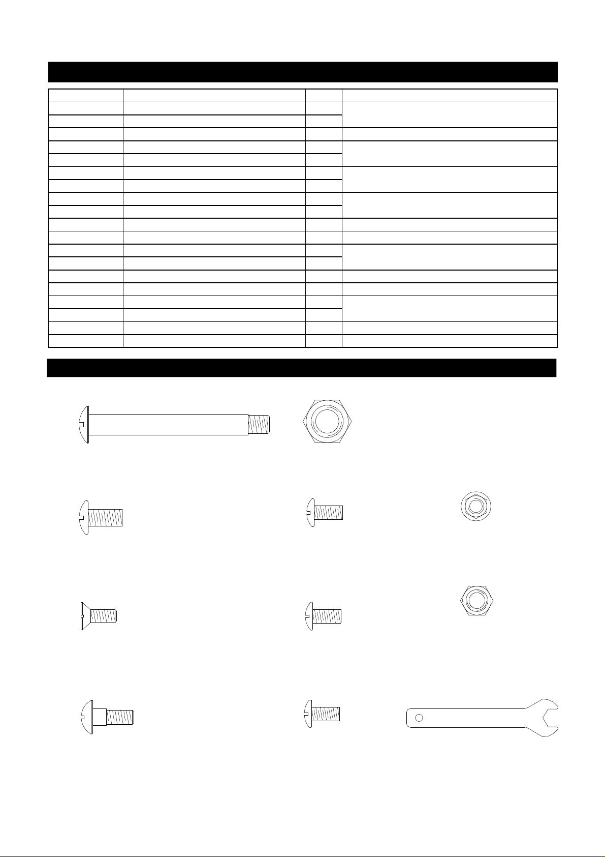
Hardware Parts List for Models GT2411ALP
PART # PART DESCRIPTION QTY PURPOSE OF PART
S271G0365A Phillips Head Wheel Bolt 3/8" x 2-15/16"
S372G0306A Nylon Lock Nut 3/8"
S112G0408A Phillips Head Screw 1/4" x 1/2"
S112G0306A Phillips Head Screw 3/16" x 3/8"
S342G0306A Flange Nut 3/16"
S112G0306A Phillips Head Screw 3/16" x 3/8"
S342G0306A Flange Nut 3/16"
S142G0306A Countersunk Flat Head Screw 3/16" x 3/8"
S342G0306A Flange Nut 3/16"
S112M0510A Phillips Head Screw M5 x 10
S112G0408A Phillips Head Screw 1/4" x 1/2"
S112G0306A Phillips Head Screw 3/16" x 3/8" 4
S112G0408A Phillips Head Screw 1/4" x 1/2" 4
S271G0466A Bolt 1/4" x 23/32" 8
S112G0306A Phillips Head Screw 3/16" x 3/8" 2
S362G0306A Hex Nut 3/16" 2
P05515131B Wrench 1
AA Battery 3
2
Install 5" Wheels
2
4 Install Cart Side Panels onto Cart Bottom Shelf
4
Install Cart Rear Panel
4
2
Install Cart Front Bracket
2
2
Install Upper Door Stop Plate
2
2 Install Lower Door Stop Plate
4 Install Grill Bowl
Install Side Shelf Brackets
Install Side Shelves
Install Battery Box Bracket
Install Casters
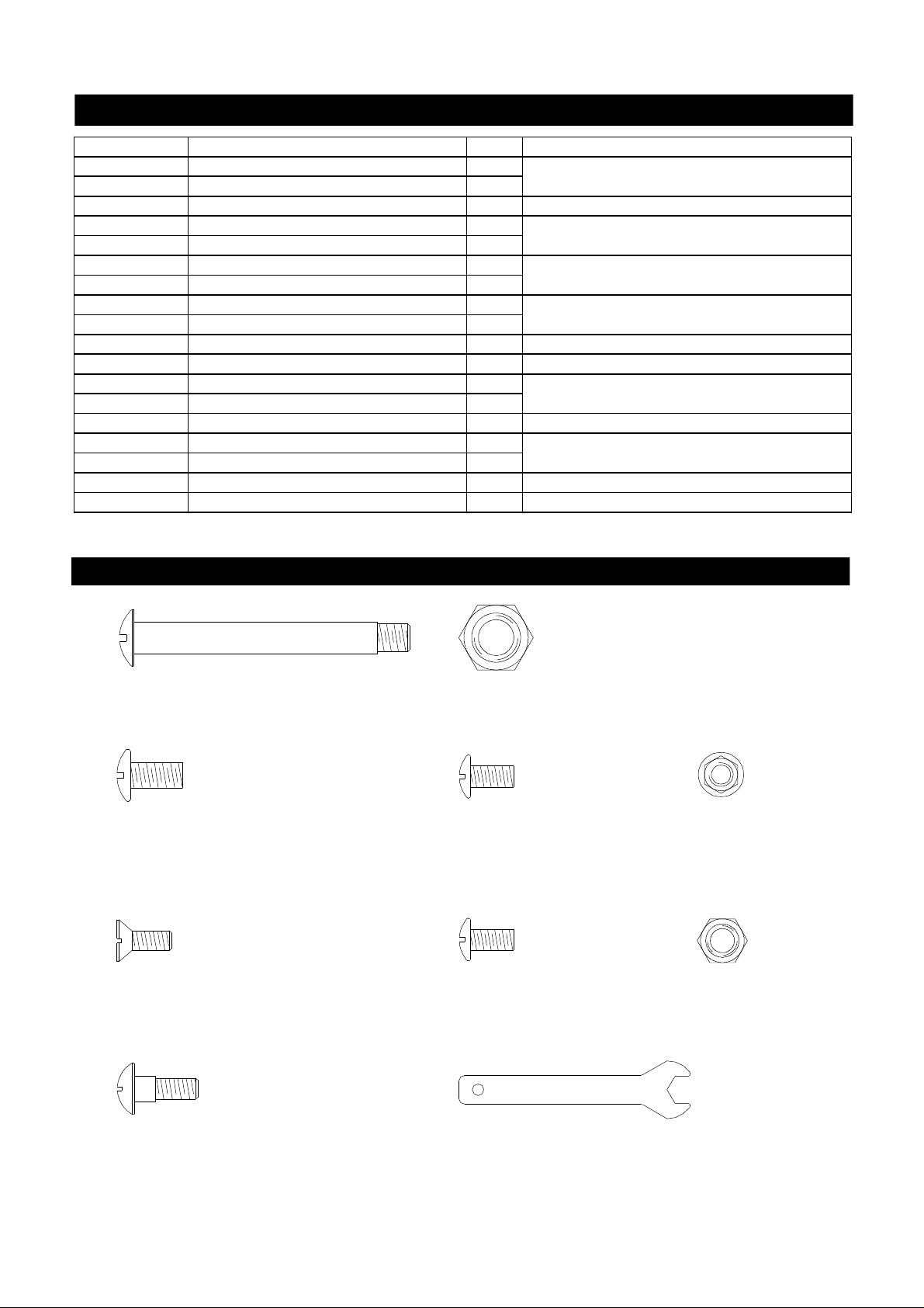
Hardware Diagram for Models GT2411ALP
Phillips Head Wheel Bolt 3/8"x2-15/16"
Qty. 2
Part # S271G0365A
Phillips Head Screw 1/4"x1/2"
Qty. 12
Part # S112G0408A
Countersunk Flat Head Screw 3/16"x3/8"
Qty. 2
Part # S142G0306A
Nylon Lock Nut 3/8"
Qty. 2
Part # S372G0306A
Phillips Head Screw
3/16"x3/8"
Qty. 12
Part # S112G0306A
Phillips Head Screw M5x10
Qty. 2
Part # S112M0510A
Flange Nut 3/16"
Qty. 8
Part # S342G0306A
Hex Nut 3/16"
Qty. 2
Part # S362G0306A
Bolt 1/4"x23/32"
Qty. 8
Part # S271G0466A
Wrench
Qty. 1
Part # P05515131B
4
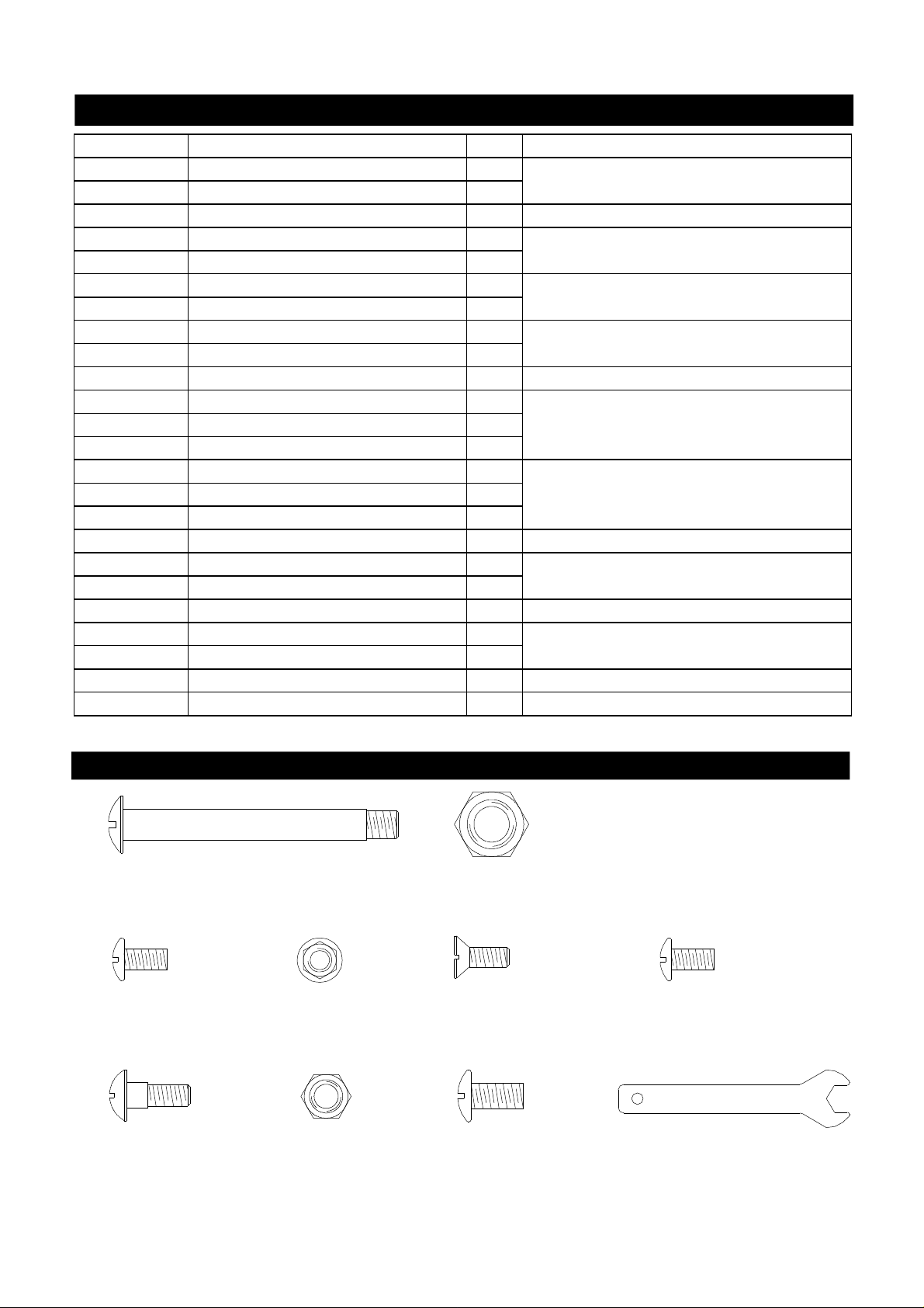
Hardware Parts List for Models GT2411ANG
PART # PART DESCRIPTION QTY PURPOSE OF PART
S271G0365A Phillips Head Wheel Bolt 3/8" x 2-15/16" 2
S372G0306A Nylon Lock Nut 3/8" 2
Install 5" Wheels
S112G0408A Phillips Head Screw 1/4" x 1/2" 4 Install Cart Side Panels onto Cart Bottom Shelf
S112G0306A Phillips Head Screw 3/16" x 3/8" 4
S342G0306A Flange Nut 3/16" 4
S112G0306A Phillips Head Screw 3/16" x 3/8" 2
S342G0306A Flange Nut 3/16" 2
S142G0306A Countersunk Flat Head Screw 3/16" x 3/8" 2
S342G0306A Flange Nut 3/16" 2
Install Cart Rear Panel
Install Cart Front Bracket
Install Upper Door Stop Plate
S112M0510A Phillips Head Screw M5 x 10 2 Install Lower Door Stop Plate
S112G0408A Phillips Head Screw 1/4" x 1/2" 4 Install Grill Bowl
S112G0306A Phillips Head Screw 3/16" x 3/8" 4
S112G0408A Phillips Head Screw 1/4" x 1/2" 4
Install Side Shelf Brackets
S112G0304A Phillips Head Screw 3/16" x 1/4" 2 Install NG Regulator
S271G0466A Bolt 1/4" x 23/32" 8 Install Side Shelves
S112G0306A Phillips Head Screw 3/16" x 3/8" 2
S362G0306A Hex Nut 3/16" 2
Install Battery Box Bracket
P05515131B Wrench 1 Install Casters
AA Battery 3
Hardware Diagram for Models GT2411ANG
Phillips Head Wheel Bolt 3/8"x2-15/16"
Qty. 2
Part # S271G0365A
Phillips Head Screw 1/4"x1/2"
Qty. 12
Part # S112G0408A
Countersunk Flat Head Screw 3/16"x3/8"
Qty. 2
Part # S142G0306A
Bolt 1/4"x 23/32"
Qty. 8
Part # S271G0466A
Nylon Lock Nut 3/8"
Qty. 2
Part # S372G0306A
Phillips Head Screw
3/16"x3/8"
Qty. 12
Part # S112G0306A
Phillips Head Screw M5x10
Qty. 2
Part # S112M0510A
Phillips Head Screw
3/16"x1/4"
Qty. 2
Part # S112G0304A
Flange Nut 3/16"
Qty. 8
Part # S342G0306A
Hex Nut 3/16"
Qty. 2
Part # S362G0306A
Wrench
Qty. 1
Part # P05515131B
5
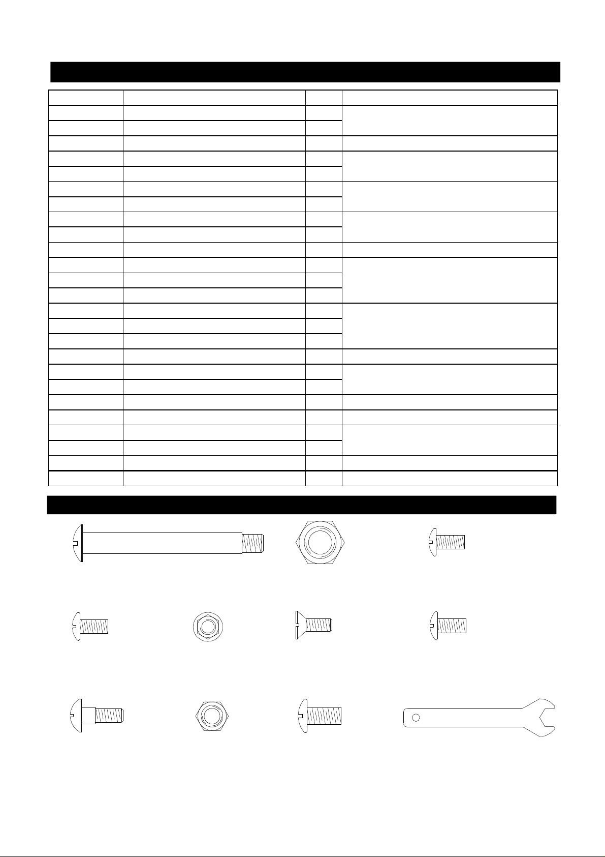
Hardware Parts List for Models GT3211ALP
PART # PART DESCRIPTION QTY PURPOSE OF PART
S271G0365A Phillips Head Wheel Bolt 3/8" x 2-15/16" 2
S372G0306A Nylon Lock Nut 3/8" 2
S112G0408A Phillips Head Screw 1/4" x 1/2" 4 Install Cart Side Panels onto Cart Bottom Shelf
S112G0306A Phillips Head Screw 3/16" x 3/8" 4
S342G0306A Flange Nut 3/16" 4
S112G0306A Phillips Head Screw 3/16" x 3/8" 2
S342G0306A Flange Nut 3/16" 2
S142G0306A Countersunk Flat Head Screw 3/16" x 3/8" 2
S342G0306A Flange Nut 3/16" 2
S112M0510A Phillips Head Screw M5 x 10 2 Install Lower Door Stop Plate
S112G0306A Phillips Head Screw 3/16" x 3/8" 2
S112G0306A Phillips Head Screw 3/16" x 3/8" 2
S342G0306A Flange Nut 3/16" 2
S112G0306A Phillips Head Screw 3/16" x 3/8" 1
S342G0306A Flange Nut 3/16" 1
S112M0510A Phillips Head Screw M5 x 10 2
S112G0408A Phillips Head Screw 1/4" x 1/2" 4 Install Grill Bowl
S112G0306A Phillips Head Screw 3/16" x 3/8" 4
S112G0408A Phillips Head Screw 1/4" x 1/2" 4
S271G0466A Bolt 1/4" x 23/32" 8 Install Side Shelves
S112G0306A Phillips Head Screw 3/16" x 3/8" 2
S362G0306A Hex Nut 3/16" 2
P05515131B Wrench 1 Install Casters
AA Battery 3
Install 5" Wheels
Install Cart Rear Panel
Install Cart Front Bracket
Install Upper Door Stop Plate
Install Partition Panel, Left
Install Partition Panel, Middle
Install Side Shelf Brackets
Install Battery Box Bracket
Hardware Diagram for Models GT3211ALP
Phillips Head Wheel Bolt 3/8"x2-15/16"
Qty. 2
Part # S271G0365A
Phillips Head Screw
3/16"x3/8"
Qty. 17
Part # S112G0306A
Bolt 1/4"x 23/32"
Qty. 8
Part # S271G0466A
Flange Nut 3/16"
Qty. 11
Part # S342G0306A
Hex Nut 3/16"
Qty. 2
Part # S362G0306A
Nylon Lock Nut 3/8"
Qty. 2
Part # S372G0306A
Countersunk Flat Head Screw
3/16"x3/8"
Qty. 2
Part # S142G0306A
Phillips Head Screw
1/4"x1/2"
Qty. 12
Part # S112G0408A
6
Phillips Head Screw M5x10
Qty. 4
Part # S112M0510A
Wrench
Qty. 1
Part # P05515131B
Hardware Parts List for Models GT3211ANG
PART # PART DESCRIPTION QTY PURPOSE OF PART
S271G0365A Phillips Head Wheel Bolt 3/8" x 2-15/16" 2
S372G0306A Nylon Lock Nut 3/8" 2
S112G0408A Phillips Head Screw 1/4" x 1/2" 4 Install Cart Side Panels onto Cart Bottom Shelf
S112G0306A Phillips Head Screw 3/16" x 3/8" 4
S342G0306A Flange Nut 3/16" 4
S112G0306A Phillips Head Screw 3/16" x 3/8" 2
S342G0306A Flange Nut 3/16" 2
S142G0306A Countersunk Flat Head Screw 3/16" x 3/8" 2
S342G0306A Flange Nut 3/16" 2
S112M0510A Phillips Head Screw M5 x 10 2 Install Lower Door Stop Plate
S112G0306A Phillips Head Screw 3/16" x 3/8" 2
S112G0306A Phillips Head Screw 3/16" x 3/8" 2
S342G0306A Flange Nut 3/16" 2
S112G0306A Phillips Head Screw 3/16" x 3/8" 1
S342G0306A Flange Nut 3/16" 1
S112M0510A Phillips Head Screw M5 x 10 2
S112G0408A Phillips Head Screw 1/4" x 1/2" 4 Install Grill Bowl
S112G0306A Phillips Head Screw 3/16" x 3/8" 4
S112G0408A Phillips Head Screw 1/4" x 1/2" 4
S271G0466A Bolt 1/4" x 23/32" 8 Install Side Shelves
S112G0304A Phillips Head Screw 3/16" x 1/4" 2 Install NG Regulator
S112G0306A Phillips Head Screw 3/16" x 3/8" 2
S362G0306A Hex Nut 3/16" 2
P05515131B Wrench 1 Install Casters
AA Battery 3
Install 5" Wheels
Install Cart Rear Panel
Install Cart Front Bracket
Install Upper Door Stop Plate
Install Partition Panel, Left
Install Partition Panel, Middle
Install Side Shelf Brackets
Install Battery Box Bracket
Hardware Diagram for Models GT3211ANG
Phillips Head Wheel Bolt 3/8"x2-15/16"
Qty. 2
Part # S271G0365A
Phillips Head Screw
3/16"x3/8"
Qty. 17
Part # S112G0306A
Bolt 1/4"x 23/32"
Qty. 8
Part # S271G0466A
Flange Nut 3/16"
Qty. 11
Part # S342G0306A
Hex Nut 3/16"
Qty. 2
Part # S362G0306A
Nylon Lock Nut 3/8"
Qty. 2
Part # S372G0306A
Countersunk Flat Head Screw
3/16"x3/8"
Qty. 2
Part # S142G0306A
Phillips Head Screw
1/4"x1/2"
Qty. 12
Part # S112G0408A
Phillips Head Screw 3/16"x1/4"
Qty. 2
Part # S112G0304A
Phillips Head Screw M5x10
Qty. 4
Part # S112M0510A
Wrench
Qty. 1
Part # P05515131B
7
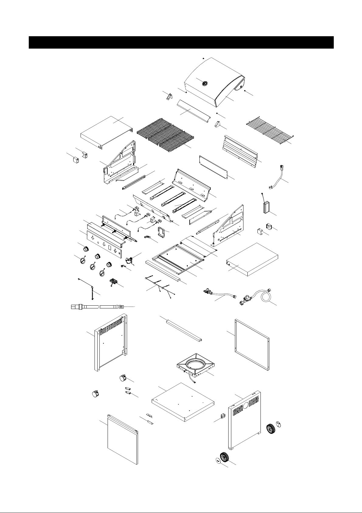
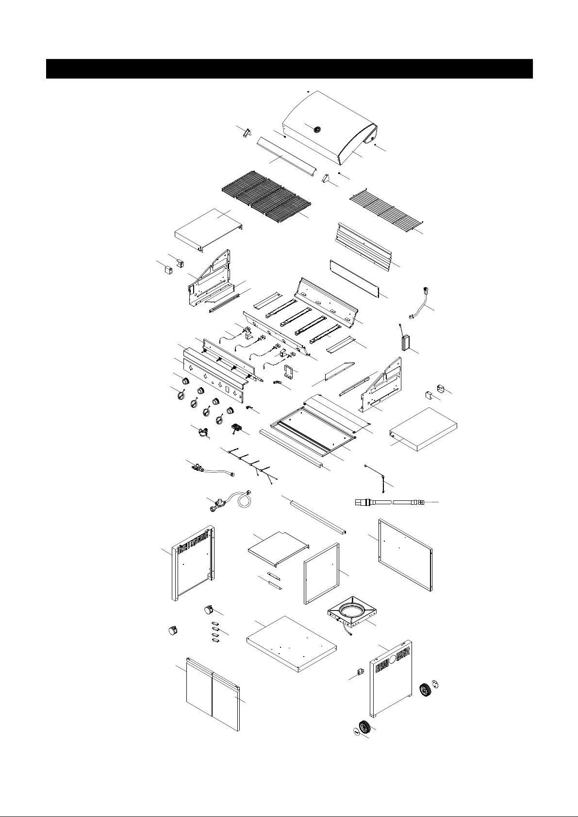
Parts Diagram for Models GT2411ALP/NG
2
6
4
1
6
48
23
49
21
22
20
19
56
16
58(LP
only)
3
12
17
27
28
29
33(NG
only)
18
9
53
34
6
5
11
31
52
13
54
55
8
48
49
32(LP
only)
34
7
14
15
25(LP
50
only)
24a
51
30
26
24b
9
10
57
35
36
39
41
44
40
45
38
46(LP
only)
37
47
42
43
8

Parts List for Model GT2411ALP/NG
KEY
1
2
3
4
5
6
7
8
9
10
11
12
13
14
15
16
17
18
19
20
21
22
23
24a
24b
25
26
27
28
29
30
31
32
33
34
35 Cart Bracket, Front P03301071D 1
36 Cart Side Panel, Left
37 Cart Side Panel, Right
38 Cart Side Panel, Rear
39 Door Assembly P04304019B 1
40 Door Magnet P05523001K 2
41 Caster, 2.5" with Brake
42 Wheel, 5 in.
43 Wheel Hub Cap
44 Door Stop Plate
45
46 Fuel Gauge Set (LPG)
47 Battery Box Bracket
Lid Assembly P0014637E4 1
Temperature Gauge P00601471A 1
Lid Handle P00213040M 1
Lid Handle Bracket, Left P00307061E 1
Lid Handle Bracket, Right P00308061E 1
Protective Pad P05518002 I 4
Bowl Panel, Left P007611564 1
Bowl Panel, Right P007621464 1
Bowl Grease Shield P06901030B 2
Bowl Bracket, Left P03305095D 1
Bowl Bracket, Right P03305096D 1
Cooking Grid P01615046H 3
Bowl wind shield, Rear P0071642R4 1
Gas Collector Box with Electrode P02609055A 3
Electrode Wire Set P02615182A 1
Main Burner P02008083B 3
Bowl Panel, Front P0073898F4 1
Bowl Panel, Rear P0076011F4 1
Gas Valve/Manifold Assembly(LPG) Y0060760 1
Gas Valve/Manifold Assembly(NG) Y0060761 1
Control Panel, Upper P02913732E 1
Control Panel, Lower(LPG) P02913741U 1
Control Panel, Lower(NG) P02913751V 1
Control Knob/Main Burner P03426453R 3
Control Knob Seat with LED Light P03415313L 3
Switch for LED Light P05353005B 1
LED Light Wire Set P02616073A 1
Fuel Gauge Display (LPG) P05393001B 1
Electric Ignitor, 4-Port
Grease Tray P02717847G 1
Grease Tray Frame P03327108D 1
Grease Tray Handle P00213041M 1
Gas Valve Heat Shield Bracket P03327107D 2
Cart Wind Shield, Rear P069060924 1
Regulator with Hose Assembly (LPG) P03601003A 1
Regulator with Hose Assembly (NG) P03641003A 1
Side Shelf P01101041D 2
Cart Bottom Shelf(LPG)
Cart Bottom Shelf(NG)
DESCRIPTION PART# QTY
P02502244C
P07617052B
P07618052B
P07624003B
P05118004A
P05123002A
P05124001C
P05510141G
P01001100D
P01001101D
Y0530017
P03311056D
1
1
1
1
2
2
2
2
1
1
1
1
9

Parts List for Models GT2411ALP/NG
KEY DESCRIPTION PART# QTY
48 Side Shelf Bracket, LF/RR P03303151D 2
49 Side Shelf Bracket, RF/LR P03303152D 2
50 Lighting Stick P05313009B 1
51 Hose, 12 FT. (NG) 3/8"ID P03703001A 1
52 Cooking Rack/Secondary P01523001J 1
53 Grease Tray Heat Shield P06903075B 1
54 Connector Wire for Fuel Gauge Set P02616074A 1
55 Battery Box P05301011V 1
56 Wind Shied/Main Burner P069060934 2
57 Extension Fitting for Manifold P03902029A 1
58 Bracket for Fuel Gauge Display P03303153D 1
Hardware Pack (LPG) P06030029A 1
Hardware Pack (NG) P06030030A 1
Operator's Manual P80134013A 1
10
Parts Diagram for Models GT3211ALP/NG
48
49
21
22
23
33(NG
only)
20
7
26
19
32(LP
only)
24b
15
14
4
34
9
10
25(LP
only)
24a
35
57
2
12
58(LP
only)
9
17
16
29
6
1
6
5
52
13
31
54
18
56
11
8
53
27
28
34
50
55
48
49
51(NG
only)
6
3
30
59
36
44
41
45
40
39a
39b
47
60
38
46(LP
only)
37
42
43
11

Parts List for Models GT3211ALP/NG
KEY DESCRIPTION PART# QTY
1 Lid Assembly P0014742E4 1
2 Temperature Gauge P00601471A 1
3 Lid Handle P00213038M 1
4 Lid Handle Bracket, Left P00307061E 1
5 Lid Handle Bracket, Right P00308061E 1
6 Protective Pad P05518002 I 4
7 Bowl Panel, Left P007611564 1
8 Bowl Panel, Right P007621464 1
9 Bowl Grease Shield P06901030B 2
10 Bowl Bracket, Left P03305095D 1
11 Bowl Bracket, Right P03305096D 1
12 Cooking Grid P01615046H 4
13 Bowl wind shield, Rear P0074805R4 1
14 Gas Collector Box with Electrode P02609055A 4
15 Electrode Wire Set P02615181A 1
16 Main Burner P02008083B 4
17 Bowl Panel, Front P0073897F4 1
18 Bowl Panel, Rear P0076010F4 1
19
20 Control Panel, Upper P02915622E 1
21
22 Control Knob/Main Burner P03426453R 4
23 Control Knob Seat with LED Light P03415313L 4
24a Switch for LED Light P05353005B 1
24b LED Light Wire Set P02616072A 1
25 Fuel Gauge Display (LPG) P05393001B 1
26 Electric Ignitor, 4-Port P02502244C 1
27 Grease Tray P02717837G 1
28 Grease Tray Frame P03327106D 1
29 Grease Tray Handle P00213039M 1
30 Gas Valve Heat Shield Bracket P03327107D 2
31 Cart Wind Shield, Rear P069060914 1
32 Regulator with Hose Assembly (LPG) P03601003A 1
33 Regulator with Hose Assembly (NG) P03641003A 1
34 Side Shelf P01101041D 2
35 Cart Bracket, Front P033010704 1
36 Cart Side Panel, Left P07617052B 1
37 Cart Side Panel, Right P07618052B 1
38 Cart Side Panel, Rear P07624002B 1
39a Door Assembly, Left P043020634 1
39b Door Assembly, Right P043030634 1
40 Door Magnet P05523001K 4
41 Caster, 2.5" with Brake P05118004A 2
42 Wheel, 5 in. P05123002A 2
43 Wheel Hub Cap P05124001C 2
44 Door Stop Plate P05510141G 2
45
46 Fuel Gauge Set (LPG) Y0530017 1
47 Battery Box Bracket P03311056D 1
48 Side Shelf Bracket, LF/RR P03303151D 2
49 Side Shelf Bracket, RF/LR P03303152D 2
50 Lighting Stick P05313029B 1
Gas Valve/Manifold Assembly(LPG) Y0060758 1
Gas Valve/Manifold Assembly(NG) Y0060759 1
Control Panel, Lower(LPG) P02915631U 1
Control Panel, Lower(NG) P02915641V 1
Cart Bottom Shelf(LPG) P01004087D 1
Cart Bottom Shelf(NG) P01004088D 1
12
 Loading...