

Grandhall Classic 217, Classic 219 Assembly Instructions Manual
Assembly instructions
Instructions d’assemblage
Montageanweisungen
Istruzioni per il montaggio
Montage-instructies
Montering
Kokoamisohjeet
Instrucciones de armado
Instruções para Montagem
Monteringsvejledning
Montering
GB
FR
DE
IT
NL
SE
FI
ES
PT
DK
NO
IE
CH
CH
CH
BE
AT
LU
gas barbecue
classic 217
classic 219
0087
CLASSIC 219 (WITH SIDE BURNER)
CLASSIC 217 (WITHOUT SIDE BURNER)

2
Ref Description Classic 217 Classic 219 Qty
1 Hood P00146179B P00146179B 1
2 Hood hinge support – left P00127314B P00127314B 1
3 Hood hinge support – right P00128314B P00128314B 1
4 Temperature gauge P00601011B P00601011B 1
5 Name plate P00407006S P00407006S 1
6 Protective pad – rear P05518001I P05518001I 2
7 Protective pad – front P05518026I P05518026I 2
8 Hood handle P00205055B P00205055B 1
8a Hood handle plates P00217001B P00217001B 2
9 Secondary cooking rack P01505018E P01505018E 1
10 Grill plate P01615031E P01615031E 2
11 Flame tamer P01705037E P01705037E 2
12 Barbecue bowl P00713384A P00713384A 1
13 Wind shield – rear upper P0075002GA P0075002GA 1
14 Burner – main P020080624 P020080624 4
15 Burner bracket P022041974 P022041974 1
16 Gas collector box with electrode – A P02606008A P02606008A 1
17 Gas collector box with electrode – B P02606009A P02606009A 1
18 Gas collector box with electrode – C P02606010A P02606010A 2
20 Electric igniter – 6 point P02502265C P02502265C 1
21 Control panel – upper P02913237A P02913237A 1
22 Control panel – lower with screen print P02913242A P02913252A 1
23 Universal hose barb – 1/4" LH thread P03901024A P03901024A 1
24 Gas valve / manifold heat shield assembly – 30 mbar Y0060498 Y0060500 1
24a Gas valve without jet – main 30 mbar P03222134A P03222134A 4
24b Jet main burner – 30 mbar P06519082A P06519082A 4
24c Manifold P05005272H P05005282H 1
24d Gas valve / manifold heat shield assembly bracket P03327045D P03327045D 2
24e Heat shield P03007193B P03007193B 1
28 Lighting stick P05313010B P05313010B 1
29 Control knob – main burner P03419123M P03419123M 4
30 Control knob seat – main P03415263L P03415263L 4
31 Grease draining tray P02717517B P02717517B 1
32 Grease receptacle P02701087B P02701087B 1
33 Bowl support frame – LR P03327057D P03327057D 2
33a Bowl support frame – LF P03327049D P03327049D 2
34 Bowl support frame – RR P03327056D P03327056D 2
34a Bowl support frame – RF P03327050D P03327050D 1
35 Side shelf – left P01102052D P01102052D 1
36 Decorative panel for side shelf – left P07503008P P07503008P 1
37 Side shelf – right P01103041D 1
38 Decorative panel for side shelf – right P07502021P P07502021P 1
39 Trolley leg – LF / RR P00907009C P00907009C 2
40 Trolley leg – RF / LR P00907010C P00907010C 2
41 Bowl support bracket P01306023D P01306023D 2
42 Trolley bottom shelf P01002062D P01002062D 1
43 Trolley panel – front P01001055D P01001055D 1
44 Gas cylinder strap P05314013V P05314013V 1
45 Trolley cross brace – lower P03305050D P03305050D 1
46 Wheel axle P05362002G P05362002G 1
48 Wheel P05103004A P05103004A 2
49 Wheel cub cap P05113001A P05113001A 2
51 Plug P06801026B P06801026B 2
52 Trolley leg seat – RF P04524001A P04524001A 1
53 Trolley leg seat – RR P04524002A P04524002A 1
55 Hot plate P05702002E P05702002E 1
56 Side burner lid P0011503IK 1
57 Side burner body P01104041D 1
58 Side burner electrode P02607007A 1
59 Side burner pot support P00801001D 1
60 Control knob – side burner P03426093M 1
61 Control knob seat – side P03415263L 1
62 Side burner P02004014G 1
63 Side burner hose P03705085F 1
65 Gas valve without jet – side 30 mbar P03222135I 1
65a Jet side burner – 30 mbar P06519084A 1
Hardware pack P06028002A P06028003A 1
Operation manual P80181012K P80181012K 1
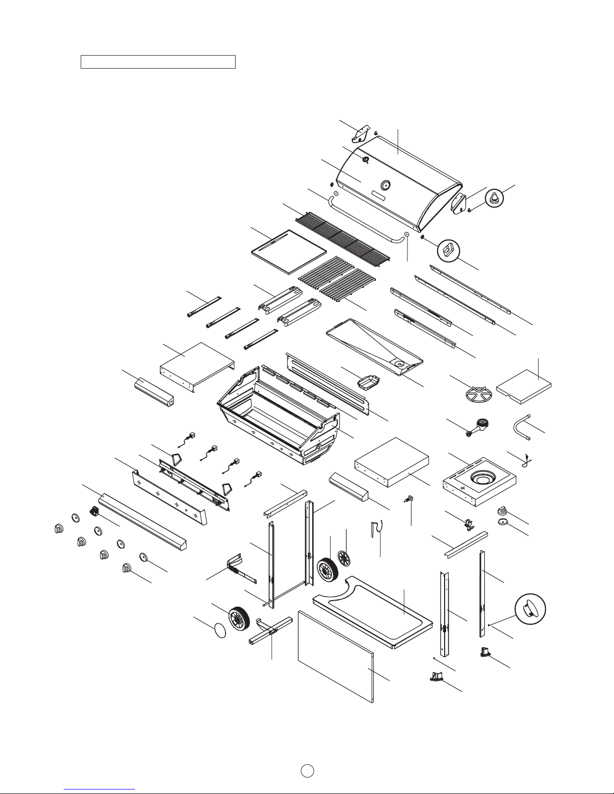
PARTS LIST
3
2
4
5
8
10
9
1
6
7
8a
55
34a RF
33a LF
34 RR
33 LR
11
14
35
36
31
32
13
59
63
62
57
37
15
12
41
56
23
38
65
60
58
61
28
40
41
39
42
49
48
44
49
48
45
43
52
53
51
51
40
46
39
30
29
20
17
18
18
16
24
24d
22
21
3
This diagram is provided to assist you identify parts
if replacement is necessary. Contact your place of
purchase to enquire about parts, availability and or
service.
PARTS DIAGRAM

4
ASSEMBLY
L
R
L
Install bowl support brackets, cross brace and trolley
leg seats to trolley legs.
1
Phillips-head screw 3/16" x 3/8"
Qty: 12
A
B
Install bowl shelf to trolley legs.
2
Phillips-head screw 3/16" x 3/8"
Qty: 12
Countersunk screw M4 x 8 mm
Qty: 2
NOTE: Left trolley legs are
without trolley legs seats
Trolley bottom shelf semi-cut
gas cylinder hole
Trolley leg seats
Trolley support
brackets
Cross brace
Step 7
A
A
A
A
B
B
 Loading...