

Gradall XL 5310 V SPECIFICATIONS
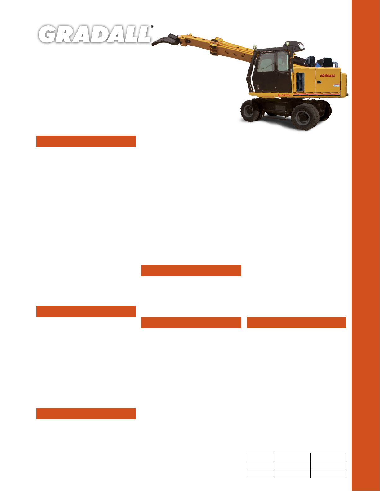
XL 5310 V
STEEL MILL MAINTENANCE
SPECIFICATIONS
Engine
• Volvo TAD571 VE Tier 4f, 4 cycle, inline 4
cylinder, liquid cooled, electronic controlled
• Vertical canister style lube and main fuel
filters and fuel/water separation with
manual feed pump attached to engine
• Water in fuel indicator and alarm
Gross Rating: 173 hp @ 2200 rpm (129kW)
590 ft lb Torque @ 1100-1500
rpm (800Nm)
Net Rating: 153 hp @ 2200 rpm (114kW)
• Variable viscous fan clutch system
• Vertical stacked hydraulic oil cooler, charge
air cooler and radiator
• Block heater
Maximum slope: 30°
• 24 volt starter
• 100 amp alternator
• Two SAE #C31-S 1000 CCA batteries
• Two-stage dr y type air cleaner with
centrifugal pre-cleaner and safety element
• Vacuator valve and service indicator
Fuel tank capacity: 82 gallons (310 L)
Operator Cab
• All-weather cab
• Tinted safety glass windows
• Acoustical lining
• Four-way adjustable seat
• AM/FM radio
• Filtered fresh air heater
• Defroster
• Air conditioner
• Front window has heat resistant glass
• Rearview mirrors on right and left sides
• Seat belt
• Swing lights
Controls
• Two electronic joysticks (hoist and bucket,
telescope and swing),
• One rocker switch (tilt) control
• Joysticks mounted on arm pods
• Quick change joystick pattern switch
located on instrument panel
• Self-centering joysticks; when controls are
released, power for movement disengages
and swing and tilt brake set automatically
• Tilting/telescoping steering column
• Hydraulic foot pedal controls braking functions
• Travel speed is regulated with an electronic
foot pedal control
• Switch on the FWD/REV selector provides
1st/2nd gear selection
• Independent rocker switches control
stabilizers, axle oscillation, park brake and
hazard lights
Engine Controls and Instrumentation
• Key operated ignition/starter switch, throttle
and main battery disconnect switch
• Air cleaner condition indicator
• Electronic monitor indicates fuel level, low
battery charge, lube oil pressure, high coolant
temperature, engine rpm and engine hours
• Fuel saving auto idle feature sends engine
rpm to idle when control circuits are in
neutral for seven seconds
Boom
• Two piece triangular telescoping boom
• Adjustable boom rollers with eccentric shafts
• 360° continuous boom tilt
• 105° boom pivot angle
• Auxiliary hydraulics
Hydraulic System
Pumps
• One load-sensing, axial piston pump; oil
flow 0-110 gpm (0-435 L/min)
• Tandem gear pump (steering, brake/pilot)
10 gpm (38 L/min), 6 gpm (23 L/min)
System Monitor
• Electronic monitor in cab indicates
- Low hydraulic fluid level
- High hydraulic fluid temperature
- System working pressure
- System pilot pressure
SYSTEM SPECIFICATIONS
Six Cylinders
• One tool: 5.0” ID, 3.0” rod
(127 mm x 76 mm), 25.9” (658 mm) stroke
• Two hoist cylinders: 4.75” ID, 3.35” rod
(121 mm x 85 mm), 31.0” (787 mm) stroke
• One telescope: 3.75” ID, 2.75” rod
(95 mm x 70 mm), 14’ (4.27 m) stroke
• Two single-acting axle oscillation cylinders:
4.528” ID, 4.528” rod (115 mm x 115 mm),
6.25” (159 mm) stroke
Three Hydraulic Motors
• Swing, 68 hp (48 kW)
• Tilt, 50 hp (37 kW)
• Propel, 113 hp (84 kW) each
Operating Pressures:
• Hoist ........................................................4,900 psi (331 BAR)
• Tilt ...............................................................4,900 psi (331 BAR)
• Swing .....................................................4,500 psi (310 BAR)
• Too l ...........................................................4,900 psi (331 BAR)
• Telescope ...................................... 4,900 psi (331 BAR)
• Propel ....................................................4,900 psi (331 BAR)
• Pilot System .......................................550 psi (38 BAR)
• Braking & Steering ..............2,400 psi (165 BAR)
• Blade & Stabilizers ..............4,000 psi (207 BAR)
Oil Capacity
• Reservoir system 65 gallons (246 L)
• Pressurized reservoir with visual oil level
gauges
Filtration System
• 10 micron return filter
• 10 micron pilot filter
• Fin and tube-type oil cooler with thermal
by-pass and relief valves
• Pressure-compensated, load-sensing
valves with circuit reliefs in all circuits
Undercarriage
• Both axles are equipped with internal
wet-disc type service brakes
• The steering axle is fitted with oscillation
lock cylinders
Tires: 10 x 20 Super-Lug
Axles: ZF Model 3070 (FTF 2090)
Transmission: ZF Model HL 290
Drive Motor: Rexroth A6 Series, 160cc/Rev
Minimum Turning Radius: 25’5” (7.75 m)
• Variable displacement high torque piston
motor powers the 2-speed power shift
transmission
• Speed mode selection can also be done
while moving
• Electronically operated travel alarm signals
excavator movement
Travel speed on flat surface - MPH (kmh):
Creeper Mode Standard Mode
First Gear
Second Gear
1.8 mph (2.9 kmh) 5.7 mph (9.2 kmh)
6.3 mph (10.1 kmh) 12 mph (19.3 kmh)
XL 5310 V STEEL MILL MAINTENANCE
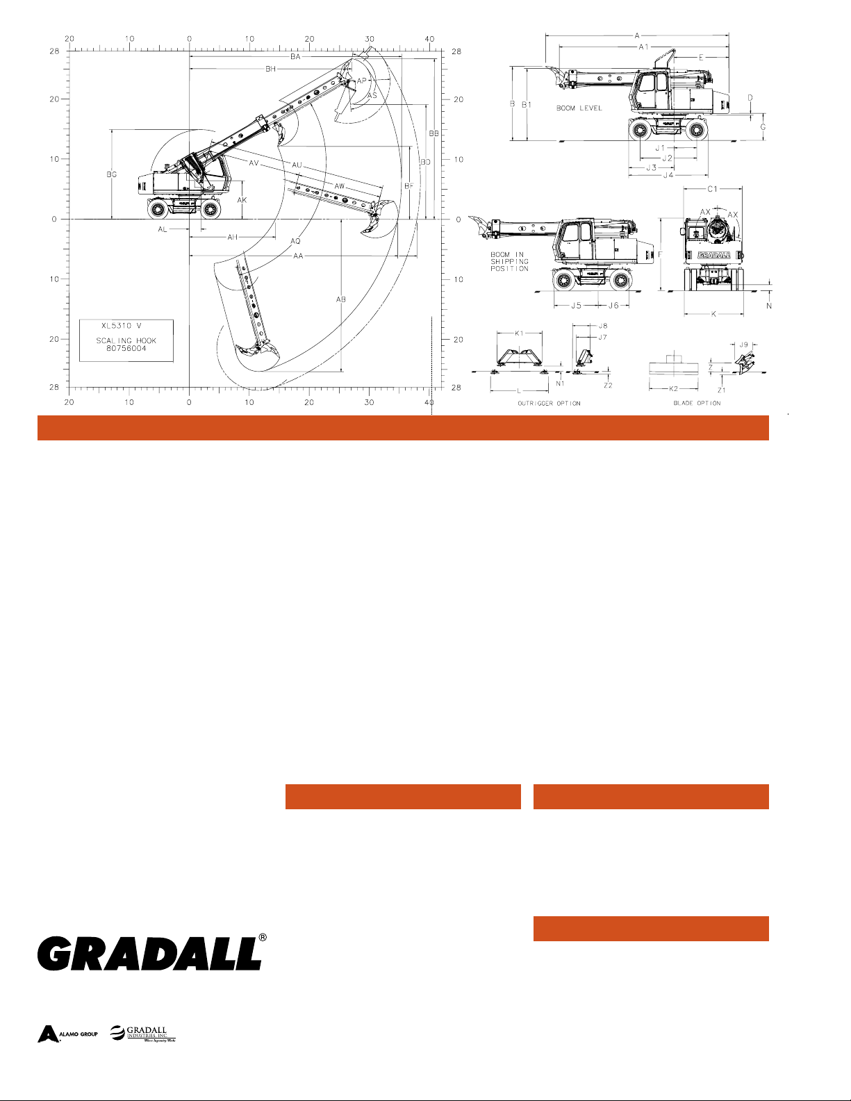
Dimensions
A Overall length with attachment open
(Travel Position): 28’4” (8.6)
A1 Overall length without attachment
(Travel Position): 26’3” (8.0)
B Overall height with attachment open
(Travel Position): 11’6” (3.5)
B1 Overall height without attachment
(Travel Position): 11’2” (3.4)
C1 Width of upperstructure: 9’0” (2.7)
D Minimum clearance, upperstructure to
undercarriage: 3” (78 mm)
E Swing clearance, rear of upper structure: 8’6” (2.6)
F Top of cab guard to groundline: 11’1” (3.4)
G Clearance, upperstructure to groundline: 4’2” (1.3)
H1 Height of optional folding lift yoke lowered: 1’9” (0.5)
H2 Height of pin of optional folding lift yoke: 3’7” (1.1)
H3 Overall height of optional folding lif t yoke: 4’0” (1.2)
H4 Height to pin of optional rigid lift yoke: 2’8” (0.8)
H5 Overall height of optional rigid lif t yoke: 3’0” (0.9)
J1 A xis of rotation to centerline of dr ive sprockets: 3’6”
(1.1)
J2 Wheelbase of undercarriage: 8’9” (2.7)
J3 A xis of rotation to front of undercarriage: 7’0” (2.1)
Specifications subject to change without notice.
Metric units are meter s (m) unless note d.
Machines shown may have opt ional equipment.
It is Gradall Policy to continually improve its products.
Therefore designs, materials and specifications are
subject to change without notice and without incurring
any liability on units already sold. Units shown may have
optional equipment.
406 Mill Ave. SW, New Philadelphia, Ohio 44663
Phone: 800-445-4752 Fax: 330-339-8468
www.Gradall.com
J4 Nominal overall length of undercarriage: 12’3” (3.7)
J5 Axis of rotation to front option attachment pin: 6’9” (2.1)
J6 Axis of rotation to rear option attachment pin: 4’9” (1.4)
J7 Outrigger length, at tachment pin to pad in up
position: 2’7” (0.8)
J8 Outrigger length, attachment pin to pad in down
position: 3’3” (1.0)
J9 Blade length, attachment pin across blade in up
position: 3’4” (1.0)
K Overall width of undercarriage: 9’1” (2.8)
K1 Overall width outrigger (up position): 8’4” (2.5)
K2 Overall width blade: 9’0” (2.7)
L Overall width outrigger (down position): 10’8” (3.3)
N Ground clearance (per SAE J1234): 11” (275 mm)
N1 Ground clearance (outrigger option): 12” (300 mm)
Z Blade above ground (option): 1’8” (505 mm)
Z1 Maximum lift of blade (option): 7’0” (166 mm)
Z2 Maximum lif t of outrigger (option): 6’0” (142 mm)
AA Maximum radius at groundline (Scaling Hook ):
34’9” (10.6 )
Maximum radius at groundline (S-29 Hammer):
37 ’ 11 ” (11. 6)
AB Maximum depth: 25’5” (7.7)
Swing
• Priority swing circuit with axial piston motor
• Planetary transmission
Swing speed: 7.0 rpm
Swing Brake
• Automatic spring-set/hydraulic release
wet-disc parking brake
• Dynamic braking is provided by the hydraulic
system
AH Minimum radius at groundline: 14’4” (4.4)
AK Boom pivot to groundline: 6’5” (2.0)
AL Boom pivot to a xis of rotation: 1’11” (585 mm)
AP Attachment tooth radius (scaling hook): 3’10” (1.2)
Attachment bit radius (S-29 Hammer): 7’0” (2.1)
AQ Boom pivot angle: 30° Up and 75° Down
AS Attachment pivot angle: 165°
AU Maximum telescoping boom length
(boom pivot to attachment pivot): 29’6” (9.0)
AV Minimum telescoping boom length
(boom pivot to attachment pivot): 15’6” (4.7)
AW Telescoping boom travel: 14’0” (4.3)
AX Boom tilt angle (continuous): 360°
BA Ma ximum radius of working equipment: 35’4” (10.8)
BB Maximum height of working equipment: 26’9” (8.2)
BD Minimum clearance of attachment with pivot at
maximum height: 19’2” (5.8)
BF Minimum clearance of attachment at maximum
boom height: 12’2” (3.7)
BG Ma ximum height of working equipment with
attachment below groundline: 14’11” (4.5)
BH Radius of attachment tooth at maximum height:
27’1” ( 8.2 )
Function Forces
Rated Boom Force: 24,941 lbs (111 kN)
Rated Ripper Tooth Force:
25,405 lbs (113 kN)
Boom Rotating Torque:
25,800 ft lb (34,980 Nm)
Boom Rotating Speed: 7.0 r pm
Weight
• Approximate working weight with 36” (914
mm) excavating bucket, fuel tank half full
- 55,926 lbs (25,368 kg)
Outriggers: 2,720 lbs (1,234 kg)
Blade: 1,529 lbs (671 kg)
Form No. 11842 5/20
Printed in USA
 Loading...