


534B
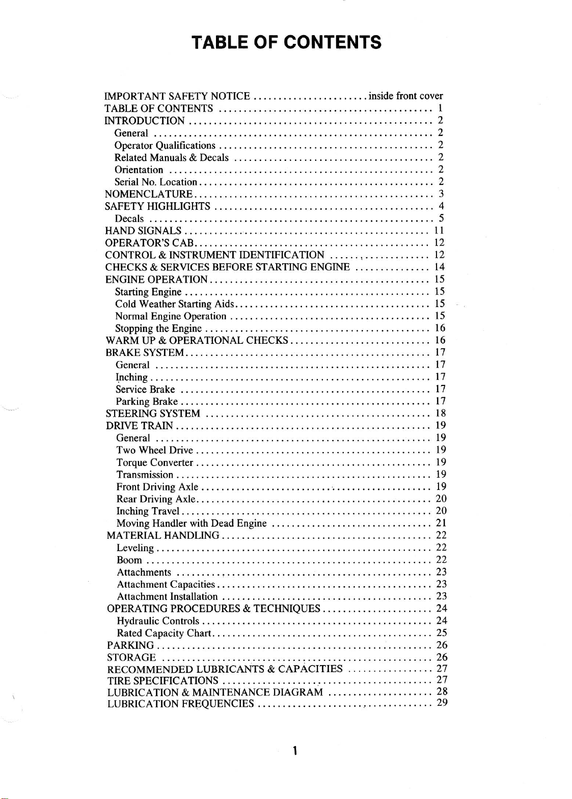
Table of contents
 Loading...
®
SERVICE MANUAL
®
534B
®
CORPORATE OFFICE
9103-1390
July 2002
Starting S/N
8744110 thru 0144859
Also S/N 8744079 &
(534B-9) S/N 0144860
thru S/N 0144899
GRADALL DIVISION
JLG INDUSTRIES, INC.
1 JLG DRIVE
McConnellsburg, PA
17233-9533
USA
Telephone: (717) 485-5161
Fax: (717) 485-6417
JLG INDUSTRIES, INC.
406 Mill Avenue S.W.
New Philadelphia, OH
44663
USA
Telephone: (330) 339-2211
Fax: (330) 339-8458


®
®
OPERATION & LUBRICATION MANUAL
®
534B
Form #48729
CORPORATE OFFICE
9103-1380
July 2002
Starting S/N
8744110
Also Covers
S/N 8744079
Original Issue 4/87
GRADALL DIVISION
JLG INDUSTRIES, INC.
1 JLG DRIVE
McConnellsburg, PA
17233-9533
USA
Telephone: (717) 485-5161
Fax: (717) 485-6417
JLG INDUSTRIES, INC.
406 Mill Avenue S.W.
New Philadelphia, OH
44663
USA
Telephone: (330) 339-2211
Fax: (330) 339-8458


IMPORTANT SAFETY NOTICE
Safe operation depends on reliable equipment and proper operating
procedures. Performing the checks and services described in this manual will
help to keep your Gradall Material Handler in reliable condition and use of
the recommended operating procedures can help you avoid accidents.
Because some procedures may be new to even the experienced operator we
recommend that this manual be read, understood and followed by all who
operate the unit.
Danger, Warning and Caution notes in this manual and the FIEI Rough Terrain
Forklift Safety Manual will help you avoid injury and damage to the equipment.
These notes are not intended to cover all eventualities; it would be impossible to
anticipate and evaluate all possible applications and methods of operation for
this equipment.
Any procedure not specifically recommended by The Gradall Company must
be thoroughly evaluated from the standpoint of safety before it is placed in
practice. If you aren’t sure, contact your Gradall Material Handler
Distributor before operating.
Do not modify this machine without written permission from The Gradall
Company.
NOTICE
The Gradall Company retains all
proprietary rights to the information contained in this manual.
The Company also reserves the
right to change specifications without notice.
Gradall is a registered trademark for
hydraulic excavators, hydraulic material handlers and attachments manufactured by The Gradall Company.
Form No. 48729
The Gradall Company
406 Mill Avenue, S.W., New Philadelphia, Ohio 44663
INTRODUCTION
General
The manual provides important information
familiarize you with safe operating procedures and
operator maintenance requirements for the Gradall/
534-B Material Handler.
If you have any questions regarding the material
handler, contact your Gradall Material Handler
Distributor.
Operator Qualifications
Operators of the material handler must be in good
physical and mental condition, have normal reflexes
and reaction time good vision and depth perception
and normal hearing. He/she* must not be using
medication which could impair his abilities nor be
under the influence of alcohol or any other drug
during the work shift.
The operator should also possess a valid, applicable
driver’s license and must have completed a course of
training in the safe operation of this type of material
handling equipment.
Related Manuals & Decals
Separate publication are furnished with the
material handler to provide information
concerning safety, replacement parte, maintenance
procedures, theory of operation and vendor
components. Replacement manuals, decals and
instructions plates can be ordered from your Gradall
Material Handler Distributor.
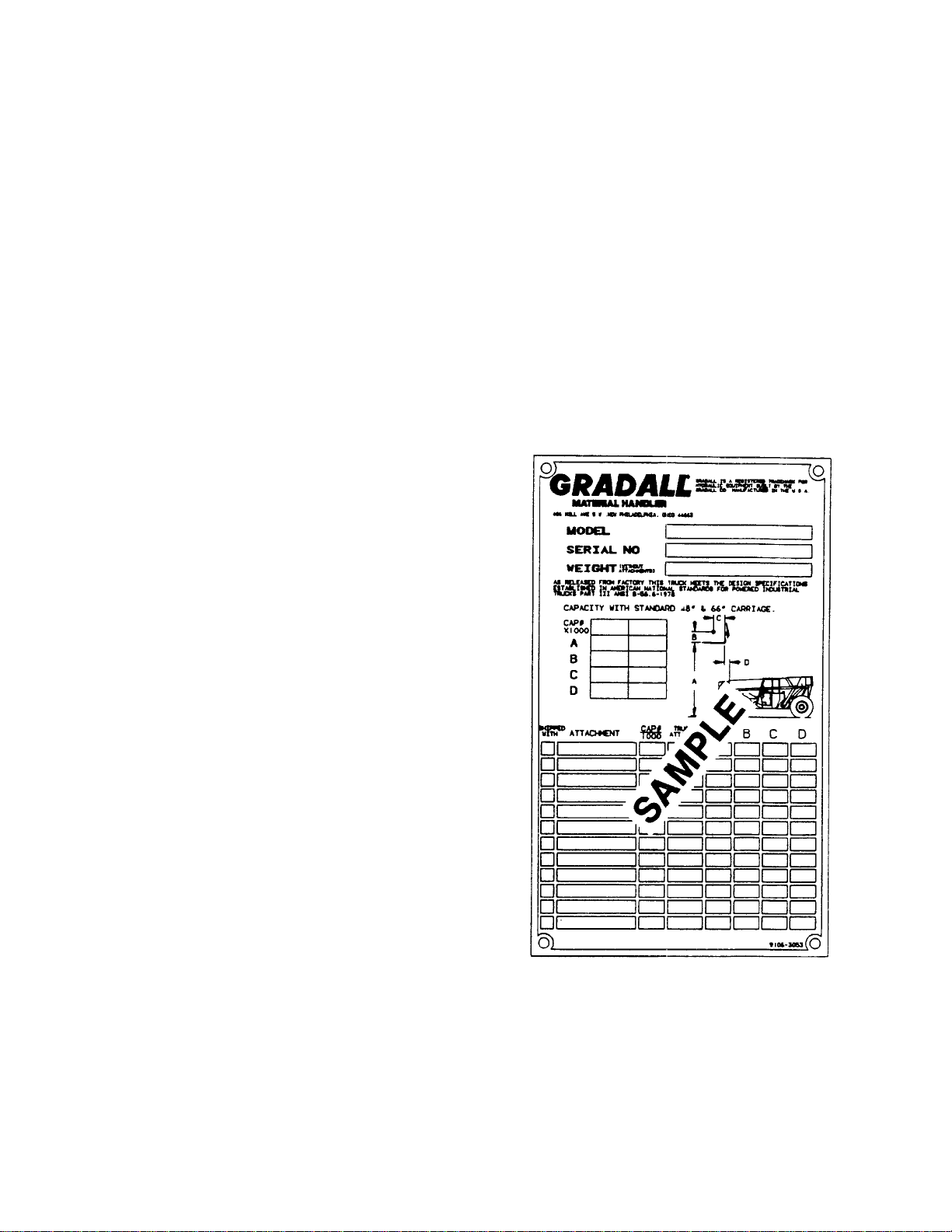
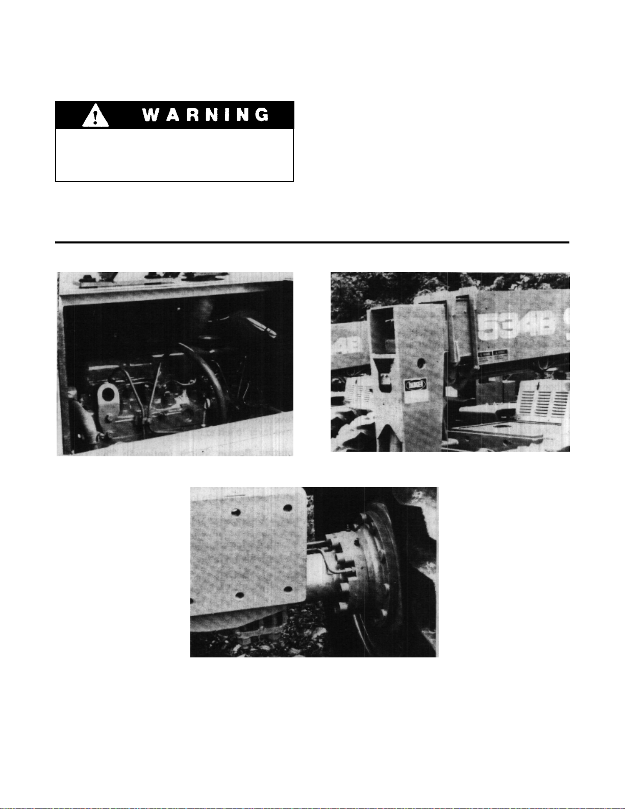
Serial Number Location
Specify Model and Serial Numbers when ordering
parts and when discussing specific applications and
procedures with your distributor. The model/serial
number plate located on the cate wall to the right
of the Operator’s seat pedestal.
In addition, the operator must read, understand and
comply with instructions contained in the following
material furnished with the material handler:
This Operator’s Manual
FIEI Rough T errain Forklift Safety Manual
Gradall Material Handler Safety Manual
All instruction decals and plates
Any optional equipment instructions furnished
The operator must also read, understand and
comply with all applicable Employer, Industry and
Governmental rules, standards and regulations.
Regardless of previous experience operating similar
equipment, the operator must be given sufficient
opportunity to practice with the 534-B Material
Handler in a safe, open area (not hazardous to people
or property) to develop the skills and “feel” required
for safe, efficient operation.
¬
Though no offense or discrimination is intended,
only the masculine pronouns will be used
throughout the remainder of this manual.
Orientation
When used to describe location of componente in
the material handler, the directions front, rear,
right and left relate to the orientation of a person
sitting in the operator’s seat.
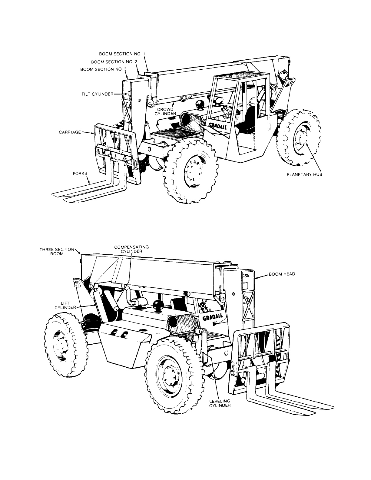
Nomenclature
The illustrations on page 3 include nomenclature
applied to major components of the material handler.
The term “handler” will be used throughout the
balance of this manual in place of the words “material
handler”.
2
NOMENCLATURE
3

SAFETY HIGHLIGHTS
Read and understand this manual, the Gradall Material Handler Safety Manual and all instructional
decals and plates before starting, operating or performing maintenance procedures on this equipment.
Most safety notes included in this manual involve
characteristics of the Model 534-B Material
Refer to the FIEI Rough Terrain Forklift Safety
Manual and the Gradall Material Handler Safety
Manual for safety precautions relating to general
material handling procedures and practices.
Handler.
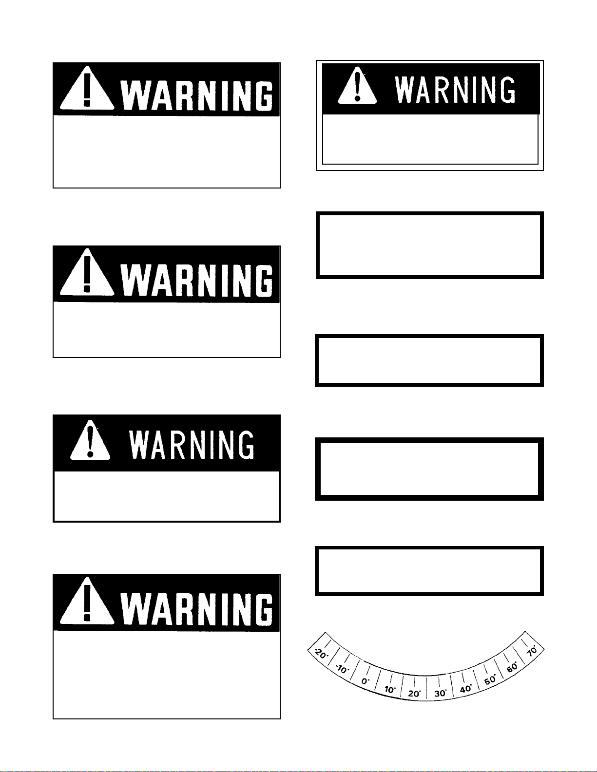
Watch for these symbols; they are used
to call your attention to safety notices.
Operators of this equipment must have successfully
completed a training program in the safe operation
of this type of material handling equipment.
Regardless of previous experience operating similar
equipment, the proper operator must be given
opportunity to practice with the 534-B Material
Handler in a safe open area (not hazardous to
or property) to develop the skills and “feel” re
for safe, efficient operation.
sufficient
people
quired
DANGER
This symbol indicates a hazard which could
would result in high probability of death or
serious injury if proper precautions are not
taken.
This symbol indicates a hazard which could
result in death or serious if proper
precautions are not taken.
This symbol indicates a hazard which could
result in injury or damage to equipment or
property if proper precautions are not taken.
4
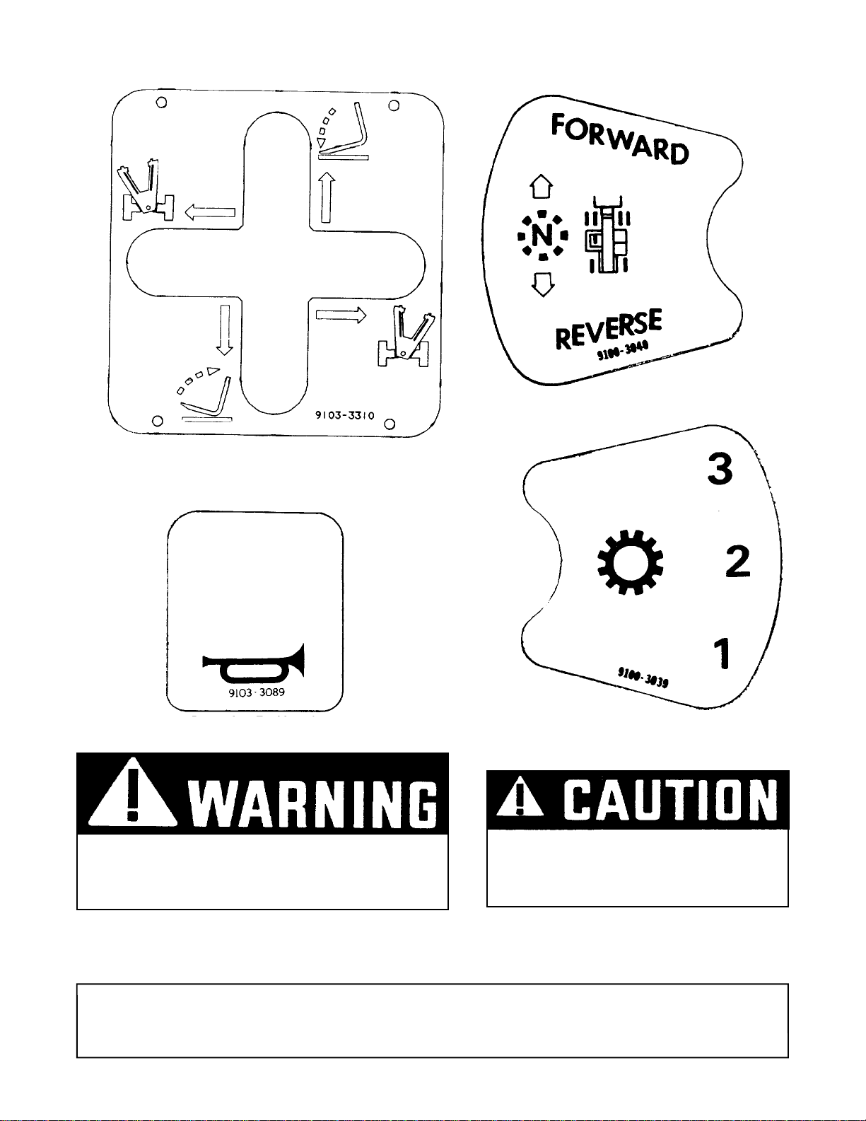
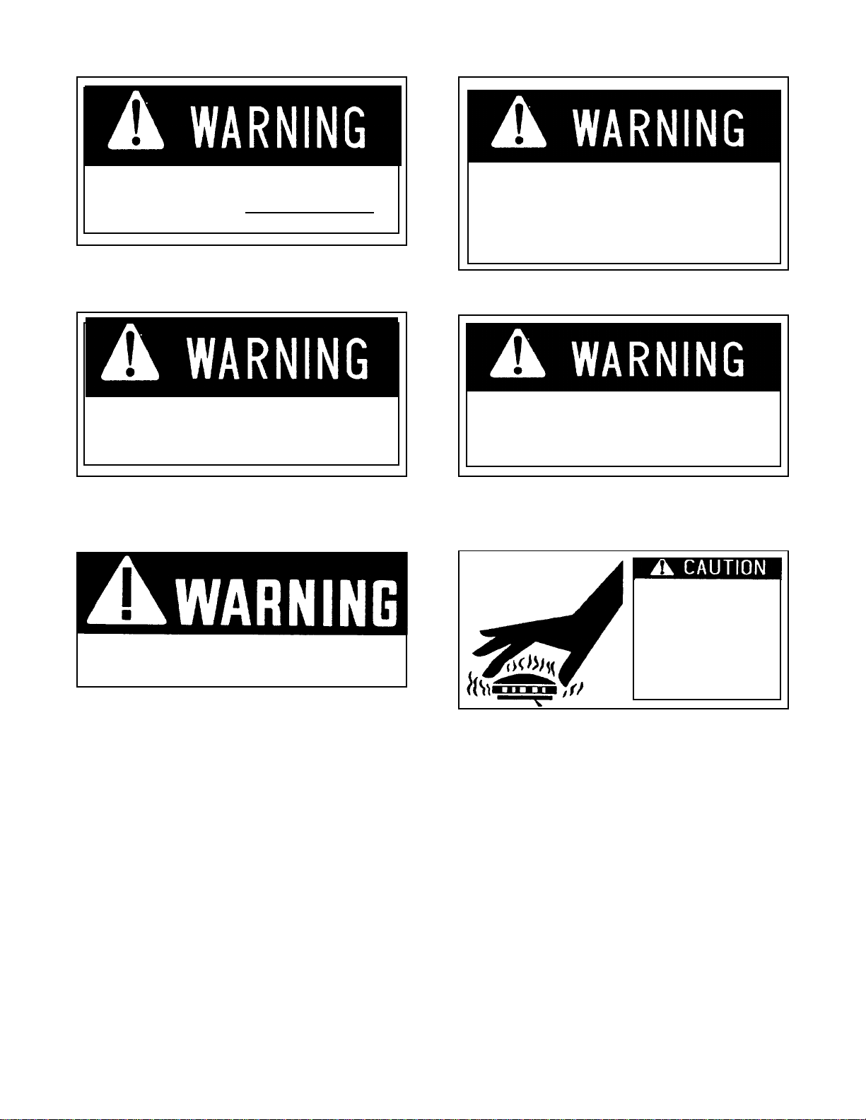
Decals Inside Cab
Located on Dashboard
Part No. 9100-3040
Located on Dashboard
9103-3310
Located on Dashboard
Part No.9103-3089
DO NOT OPERATE MACHINE
WITHOUT PROPER CAPACITY
CHART IN PLACE
Located on Dashboard
Part No. 9100-3039
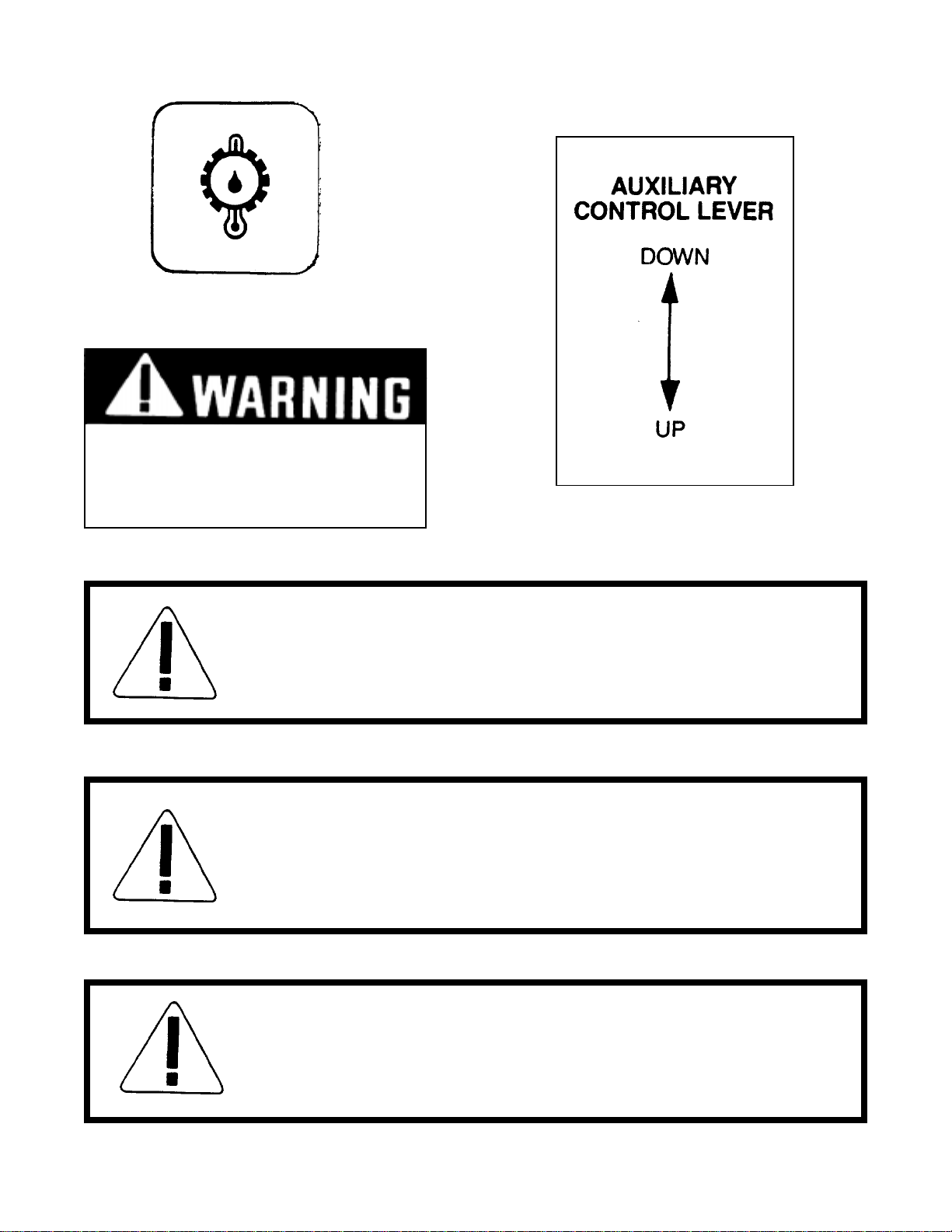
TO PREVENT ENGINE RING GEAR DAMAGE,
WAIT 10 SECONDS AFTER ENGINE
ROTA TION STOPS BEFORE A T A TTEMPTING
TO RESTART .
W ARNING!
Located on Firewall
Part No. 9103-3010
Located on Dashboard
Part No. 9103-3157
LEVEL GRADALL HANDLER BEFORE LIFTING
ANY LOAD ABOVE 4 FEET
5
Located on Dashboard
Part No.9103-3014
Decals Inside Cab (cont.)
9100-3041
Located on Dashboard
Part No. 9100-3041
BRAKING CAPACITY IS
REDUCED WHEN ENGINE
IS NOT RUNNING.
9103-3135
Located on Dashboard
Part No. 9103-3135
9103-3244
Located on Dashboard
Part No. 9103-3244
W ARNING:
SHUT OFF ENGINE AND SET BRAKES BEFORE
LEAVING GRADALL HANDLER UNATTENDED
Located on Firewall
Part No. 9100-3029
WARNING:
ON GRADES AND UNEVEN GROUND PLACE FORKS
IN CARRY POSITION (APPROX. 12" ABOVE GROUND)
BEFORE MOVING GRADALL HANDLER
Located on Firewall
Part No. 9100-3050
WARNING:
OPERATOR PROTECTION (SUCH AS HARD HATS,
SAFETY GLASSES AND/OR EAR MUFFS) SHOULD BE
WORN WHEN JOB CONDITIONS WARRANT
Located on Firewall
Part No. 9100-3036
9100-3050
9100-3036
6
Decals Inside Cab (cont.)
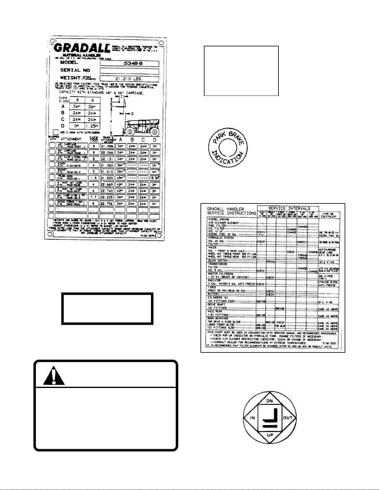
PARK BRAKE
PULL TO SET
PUSH TO RELEASE
LIGHT IDENTIFICA TION
P ARK BRAKE
INSTRUCTIONS
P ARKING BRAKE
Located on Firewall
Part No. 9103-3279
START
9104-
BUTTON
Located on Front Face of Dashboard
Part NO. 9104-3207
3207
WARNING
DO NOT OPERATE THIS MACHINE
WITHOUT FIRST READING THE
OPERA T OR’S MANUAL. IF A
MANUAL IS NOT A V AILABLE,
REFER TO AN AUTHORIZED
GRADALL DEALER.
9103-3103
Located on Manual Holder
Part No. 9103-3103
Located on Manual Holder
Part No. 9106-3031
Located on Boom Lever Knob
Part No. 9100-3044
7
GFHGHGFH
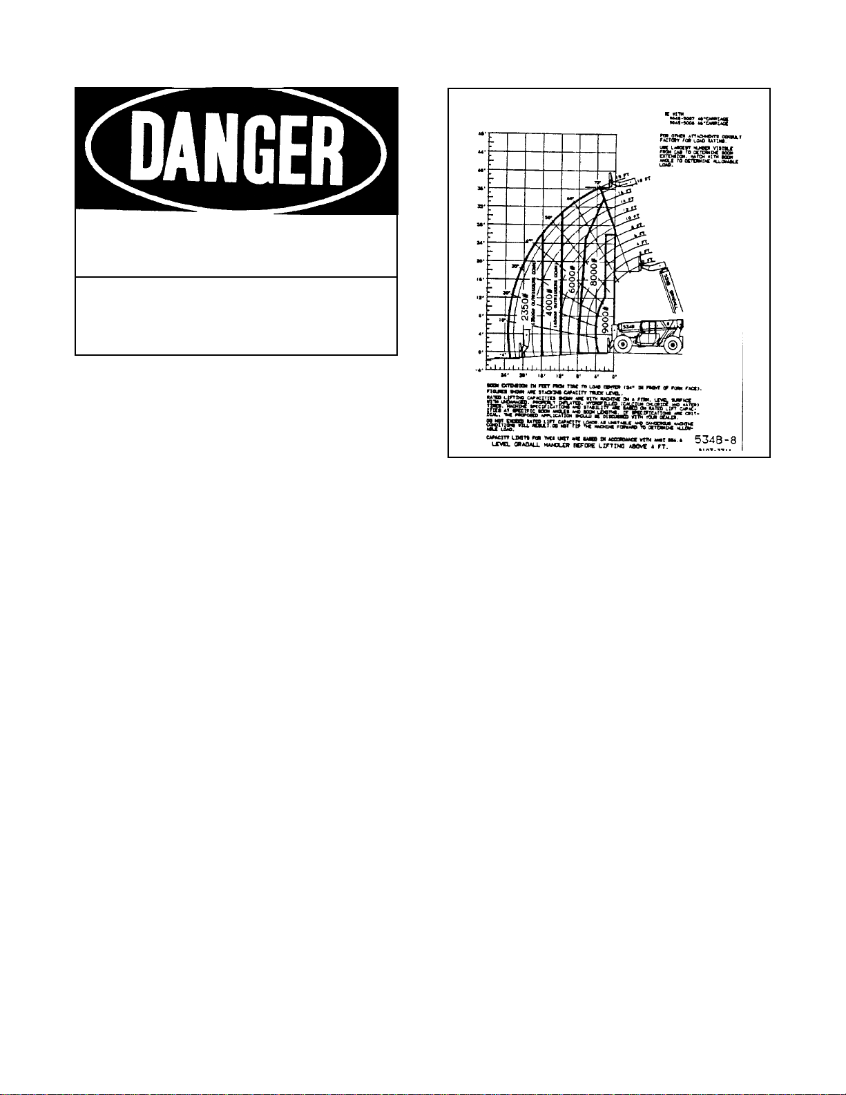
Decals Inside Cab (cont.)
CAPACITY CHART: MODEL 5348-8
RA TED CAPACITY 2 FT . LOAD CENTER
DEATH
UNLAWFUL
FOR MINIMUM CLEARANCES OF HIGH VOLT AGE LINES IN EXCESS OF 50,000 VOL TS, SEE
YOUR LOCAL STA TE ANDFEDERAL REGULA TIONS DO NOT DEFACE OR REMOVED THIS
SIGN FROM THIS MACHINE
OR INJURY MAY RESULT FROM
CONT ACTING ELECTRICAL LINES.
TO PLACE ANY PART OF THIS
MACHINE OR LOAD WITHIN 10
FEET OF HIGH VOLTAGE LINES
OF UP TO 50,000 VOL TS.
Located on Mudguard
Part No. 8360-1011
88
9
9103-3311
Located on Dashboard
Part No. 9106-3034
Optional Lift Capacity Charts are
located on Firewall.
8
Decals Outside Cab
FUEL - DIESEL
EXTINGUISH ALL OPEN FLAME
AND SMOKING MA TERIALS
WHEN REFUELING.
Located on Fuel Tank
Part No.9100-3052
DO NOT INSERT HAND IN
OPENING WHILE ENGINE
IS RUNNING
Located on Radiator
Part No 9103-3011
9100-3052
9103-3011
NO RIDERS
9104-3211
Located on Hydraulic Reservoir & Left of Cab Door
Part No. 9104-3211
COOLANT
9100-3032
Located on Radiator
Part No. 9100-3032
DIESEL FUEL
7702-3308
CHECK TO ASSURE QUICK SWITCH
PIN IS FULL Y ENGAGED AND LOCKED
AFTER A TTACHMENT CHANGE
Located on Boom Head
Part No. 9103-3023
2-9103-3023
USE TWO
HANDS WHEN
Located on Fuel Tank
Part No. 7702-3308
TIRE PRESSURE
55 PSI
Located on Wheel Rims REAR: 55 psi
Part No. 9105-9104 FRONT: 65 psi
HYDRAULIC OIL
7702-3006
Located on Hydraulic Reservoir
Part No. 7702-3006
CLIMBING ON
MACHINE.
Located Left of Cab Door
Part No. 7702-3003
7702-3003
Located on Boom
Part No. 9100-3031
9
Decals Outside Cab (cont.)
DO NOT USE THIS MACHINE
FOR LIFTING PERSONNEL.
9104-3215
Located on Mudguard
Part No. 9104-3215
DO NOT STAND UNDER
LOAD OR BOOM
9104-3217
Located on Boom
Part No. 9104-3217
PINCH POINT AREA
TO PREVENT INJURY, KEEP
CLEAR ANYTIME MACHINE
IS RUNNING
Located Below Boom Pivot
Part No. 9104-3209
DO NOT USE BOOM
AS WALKAWAY
Located on Boom
Part No. 9104-3216
9104-3209
9104-3216
HOT EXHAUST
Located on Exhaust Guard
Part No. 7734-3018
PRESSURIZED-
COOLING SYSTEM
REMOVE CAP
SLOWL Y
9104-3210
Located on Radiator
Part No. 9104-3210
10
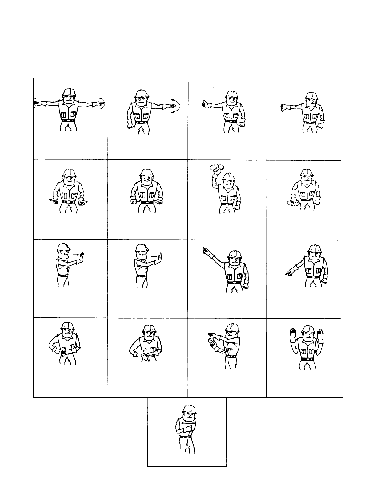
Standard Signals - When handler work conditions
require hand signals, they shall be provided or
posted conspicuously for the use of both signalman
and operator. No handler motions shall be made
unless signals are clearly understood by both
signalman and operator.
EMERGENCY STOP - With both
arms extended laterally hands open
downward, move arms back and
forth.
STOP - With either arm extended
laterally, hand open downward,
move arm back and forth.
Special Signals - When signals for auxiliary
equipment functions or conditions not covered are
required, they shall be agreed upon in advance by
the operator and signalman.
RAISED BOOM - With either arm
extended horizontally, finger
closed, point thumb upward.
HAND SIGNALS
Instructions - When it desired to give instructions
to the operator other than provided by the
established signal system all handler motions shall
first be stopped.
LOWER BOOM - With either arm
extended horizontally, fingers
closed, point thumb downward.
EXTEND TELESCOPIC BOOM With both hands clenched, point
thumbs outward.
MOVE LOAD OUT HORIZONTALLY
With either arm extended, hand
raised and open toward direction of
movement, move hand in direction of
required movement.
CLOSE BUCKET - Hold one hand
closed and stationary. Rotate other
hand in small vertical circle with
forefinger pointing horizontally at
closed hand.
RETRACT TELESCOPIC BOOM With both hands clenched, point
thumbs inward.
MOVE LOAD HORIZONTALLY With either arm extended, hand
raised and open toward direction of
movement, move hand in direction of
required movement.
OPEN BUCKET - Hold one hand
open and stationary. Rotate other
hand in small vertical circle with
forefinger pointing horizontally at
open hand.
RAISED LOAD VERTICALL Y - With
either forearm vertical, forefinger
pointing up, mover hand in small
horizontal circle.
TILT FORKS UP - With one arm held
at side, extend other arm upward at
about 45°.
MOVE SLOWLY - Place one hand
motionless in front of hand giving
motion signal. (Raise load slowly is
shown.)
LOWER LOAD VERTICALLY - With
either arm extended downward
forefinger pointing down, move hand
in small horizontal circle.
TILT FORKS DOWN - With one arm
held at side, extend other arm
downward at about 45°
THIS FAR TO GO - With hands raised
and open inward, move hands
laterally, indicating distance to go.
STOP ENGINE - Draw thumb or
forefinger across throat.
11
The standard cab is open on three sides and includes
an overhead guard to provide protection from
falling objects.
Never operate the handler unless the
overhead guard is in place and in good
condition.
A fully enclosed cab with Plexiglass windows and a
lokable door is available as an option. The cab
door can be secured in the fully opened or closed
position. Be sure the door is fully secured when
operating the handler.
The operator’s seat is equipped with a seat belt and
includes fore and aft adjustment to compensate for
OPERA TOR’S CAB
variations in operator size. The adjustment
release/lock lever is located beneath front edge of
seat belt at all times.
An optional windshield wiper is available for use
with enclosed cabs. An ON/OFF control switch is
located on the wiper motor.
A variable speed defroster fan is available for use
with enclosed cabs. An On/Off control switch and
speed control are located on the base of the fan.
A variable speed heater fan is available for use with
units equipped with a heater. An ON/OFF/SPEED
CONTROL knob is located on the dashboard. Hot
water to the heater can be controlled by a valve at
the engine.
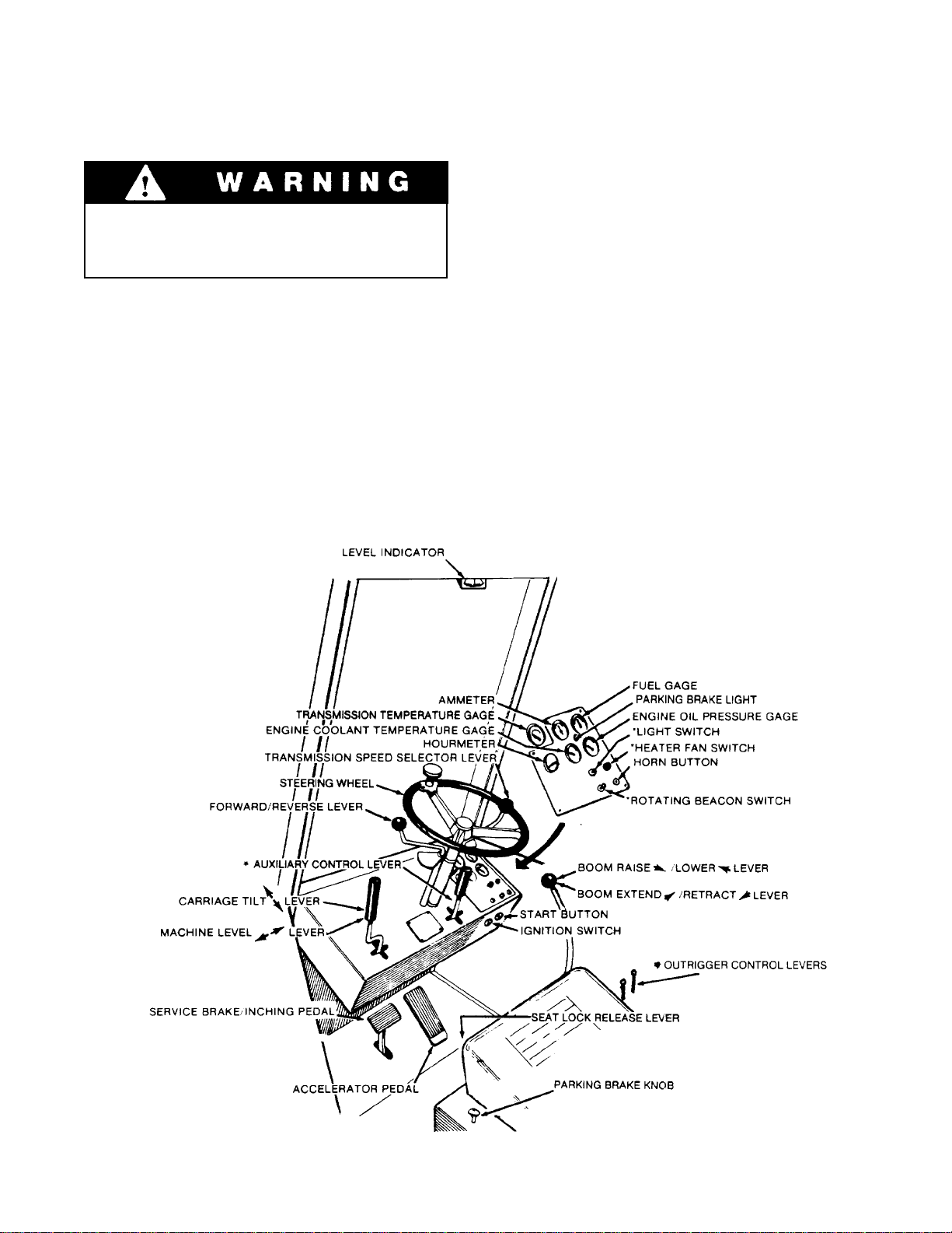
CONTROL AND INSTRUMENT IDENTIFICATION
*Items preceded by an asterisk and may not be furnished on your handler.
12

A brief description of controls and Instruments is provided here as a convenience for
the operator. These descriptions DO NOT
provide complete operating instructions.
Read and understand this manual and the
FIEI Rough Terrain Forklift Safety Manual
before operating the handler.
Engine Oil Pressure Gage: This gage displays engine
oil pressure. Normal operating pressure is 35-50 psi
(241-345 kPa).
Forward/Reverse Lever: This lever engages forward
or reverse travel. Push lever fully forward for forward
travel; pull lever fully to rear for reverse travel or
Read and understand this manual and the
move lever to centered position for neutral.
Fuel Gage: This gage displays level of fuel in fuel
tank.
NOTE: These descriptions are provided in alphabetical sequence in accordance with the nomenclature shown on the facing page.
Accelerator Pedal: The accelerator pedal is connected to the engine speed control by a cable to
provide accurate engine speed control. Depress pedal
to increase speed and release pedal to decrease speed.
Ammeter: The ammeter indicates the charge/discharge rate of the battery charging system. With the
engine running, a discharge reading or a continuing
high charge rate indicates a problem in the system.
Auxiliary Control Lever (optional): This lever is used
to control optional hydraulic attachments. Follow
decal instructions for lever handler movements.
Boom Extend/Retract Lever: This lever controls
boom extension and retraction. Speed is proportional
to lever actuation. Move lever to right to extend
boom or to left to retract boom.
Boom Raise/Lower Lever: This lever controls raising
and lowering the boom. Speed is proportional to lever
actuation. Pull lever to rear to raise boom or push
lever forward to lower boom.
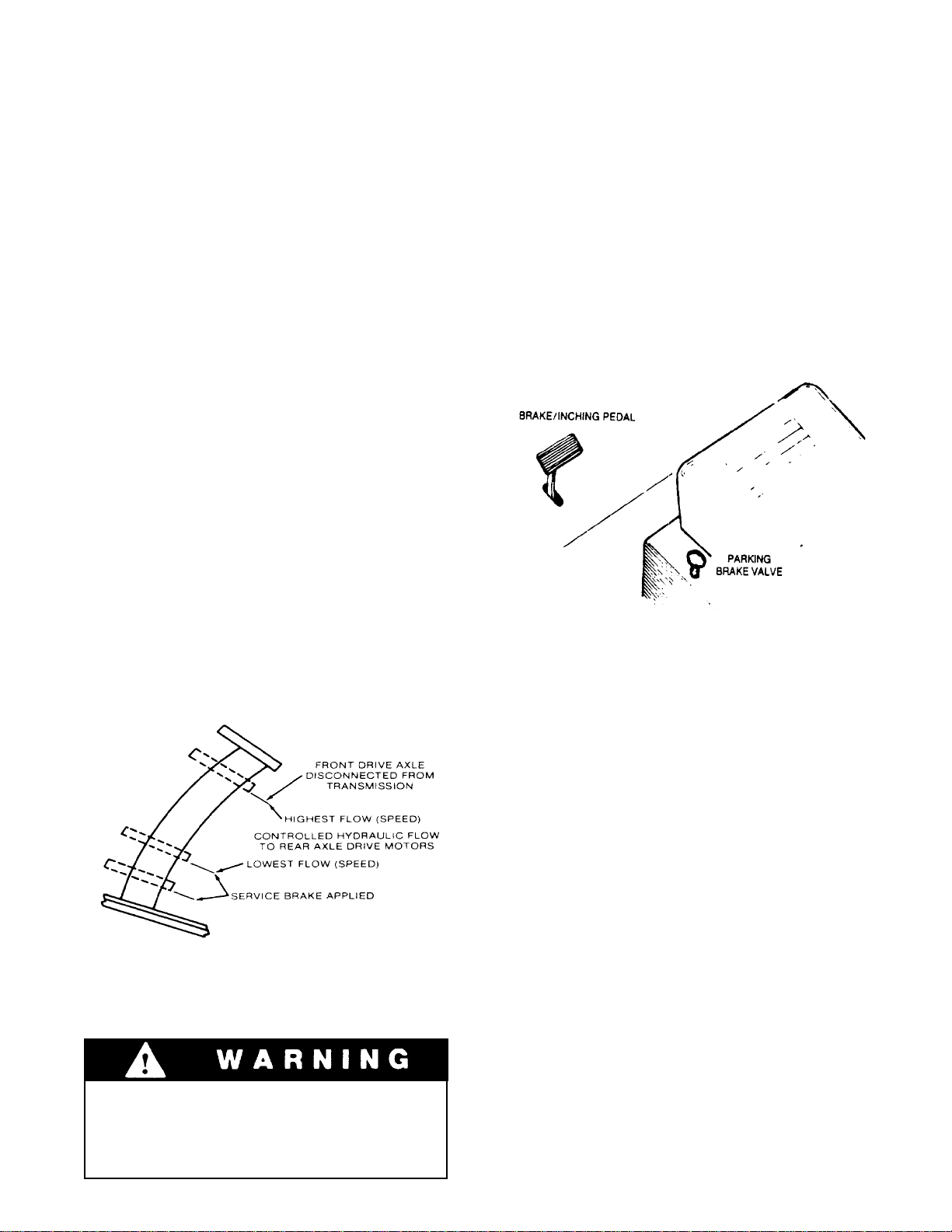
Brake/Inching Pedal: The brake/inching pedal provides service brake control and inching control. To
activate the brakes, push the pedal down. To release
the brakes, remove foot from pedal. When full brakes
are applied, the rear hydraulic drive is disconnected.
When partial brake/inching pedal movement is used,
the front wheel drive is disconnected from the
transmission. The inching feature of the rear wheel
drive system provides for smooth machine operation
at low speeds and high engine rpm.
Heater Fan Switch (optional): This rotary switch
controls heater fan. Rotate clockwise to start fan.
Continued clockwise rotation controls fan speed.
Horn Button: Depress button to sound horn.
Hourmeter: This meter indicates total time of engine
operation in hours and tenths of hours.
Ignition Switch: This switch is actuated by a key. In
ON position (turned clockwise) voltage is available
for all electrical functions. Turn key counterclockwise to stop engine and remove voltage from all
electrical functions.
Level indicator: This indicator (a bubble level)
enables the operator to determine the left to right
level condition of the handler.
Light Switch (optional): This switch controls optional
lighting which may be provided with the handler.
Machine Level lever: This lever controls the vertical
relationship of the handler frame to the front axle.
Move the lever to the right to tilt frame to right or
move lever to left to tilt frame to left.
Rotating Beacon Switch (optional): This switch
controls operation of rotating beacon.
Seat Lock Release Lewer: This lever unlocks and
locks seat position adjustment. Lift lever to unlock
and release lever to lock adjustment.
Start Button: The start button controls operation of
the engine starter motor. With ignition switch in ON
position, depress start button to actuate starter motor.
Release button to disengage starter motor.
Park Brake Control Knob: The park brake control
knob is located to the left of the operator and is used
to apply and release the parking brake. To apply the
parking brake, pull the knob up. To release the
parking brake, push the knob down.
Carriage Tilt Lever: This lever controls tilt of the
fork carriage. Speed is proportional to lever actuation. Push lever forward to tilt down or pull lever to
rear to tilt up.
Engine Coolant Temperature Gage: This gage displays engine coolant temperature. Normal operating
temperature is 180-200°F . (82-93°C.)
Steering Wheel: The steering wheel controls the
angle of rear axle wheels. Turning the steering wheel
to the right causes a right turn by angling rear wheels
to left. A left turn is caused by angling rear wheels to
right.
Transmission Speed Selector Lever: This lever permits selection of three speed ranges for forward and
reverse travel.
Transmission Temperature Gage: This gage displays
temperature of transmission fluid. Normal operating
temperature is 180-200°F . (82-93°C.).
13
CHECKS AND SERVICES BEFORE STARTING ENGINE
(To be performed at beginning of each work shift)
Use extreme caution when checking items
beyond your normal reach. Use an
approved safety ladder.
enter these ports, it can shorten the life of o-rings,
seals, packings and bearings.
When adding fluids or changing filter elements,
refer to the lubrication section of this manual to
determine the proper type to be used.
Before removing filler caps or fill plugs, wipe all dirt
and grease away from the ports. If dirt is allowed to
Complete all required maintenance before operating unit.
Service the unit in accordance with the lubrication
and maintenance schedule.
If spark arrestors are required, be sure they are in
place and in good working order.
Inspect all structural members, including attachment, for signs of damage.
Inspect unit for obvious damage, vandalism
and needed maintenance. Check for signs of fuel,
lubricant, coolant and hydraulic leaks. Open all
access doors and look for loose fittings, clamps,
components and attaching hardware. Replace
hydraulic lines that are cracked, brittle, cut or show
signs of abrasion.
14
ENGINE OPERATION
NOTE: If engine is being started at beginning of work shift be sure to perform all “CHECKS AND
SERVICES BEFORE ST AR TING ENGINE” (page 6).
Starting Engine
1. Check to be sure that all controls are in neutral
and that all electrical components (lights, heater,
defroster, etc.) are turned off. Set parking brake.
2. Insert ignition key and turn clockwise to ON
position.
3. Depress accelerator pedal approximately 1/4 to
1/3 of travel from top.
Depressing start button while engine fly wheel is rotating can cause serious damage
to engine and/or starting motor.
NOTE: If temperature requires the use of a starting
aid, and if your handler is equipped with a factoryinstalled ether starting aid, depress cold weather
button one time only before starting engine. If you
use a different starting aid, be sure to follow
manufacturer’s instructions carefully. Excessive ether
may damage engine.
Depress start button to engage starting motor.
4.
Release button immediately when engine starts. If
engine fails to start within 20 seconds, release
button and allow starting motor to cool for a few
minutes before trying again.
After engine starts, observe oil pressure gage. If
5.
gage remains on zero for more than ten seconds,
stop engine and determine cause. Correct cause
of malfunctioning before restarting engine.
Normal engine oil pressure should be in range of
35 - 50 psi (241 - 345 kPa).
Warm up engine at approximately 1/2 throttle
6.
until engine coolant temperature reaches
operating range of 180 - 200°F. (82 - 93°C.).
Cold Weather Starting Aids
Diesel engine ignition is accomplished by heat
generated when fuel/air mixture is compressed
within the cylinders. Because this heat may be
insufficient to start a cold engine in cold weather,
the use of starting aids has become common practice.
Because of the wide variety of starting aids available
it would be impractical to attempt to provide,
Normal Engine Operation
Observe gages frequently to be sure all engine
systems are tunctioning properly.
The ammeter shows the charge/ discharge rate of the
battery charging system. With the engine running, a
discharge reading (-) or a continuing high charge
reading (+) indicates a problem in the battery
charging system.
specific instructions for their use in this manual.
Carefully follow instructions furnished with your
starting aid.
If you use a starting aid employing ether or a
similar substance pay particular attention to
manutacturer’s warnings.
Avoid prolonged idling. Idling causes engine
temperature to drop and this permits formation of
heavy carbon deposits and dilution of lubricating oil
by imcompletely burned fuel. If the engine is not
being used, turn it off.
Be alert for unusual noises or vibration. When
an unusual condition is noticed, stop machine in a
safe position and shut off engine. Determine cause
and correct problem before continuing.
Always keep engine covers closed while
engine is running (it furnished).
15

Stopping the Engine
Operate engine at idle speed for a few minutes
before turning it off. This allows engine coolant
and lubricating oil to carry excessive heat away
from critical engine areas.
Do not “gun” engine before shut down; this
practice causes raw fuel to remove oil film from
cylinder walls and dilute lubricant in crankcase.
To stop the engine, allow engine to run at idle for a
few minutes, this is to allow the turbo components
to cool. Turn key counter clockwise to stop position.
Be sure to remove key from ignition switch before
leaving cab.
WARM UP & OPERATIONAL CHECKS
(To be performed at beginning of each work shift)
Complete all required maintenance before operating unit
The safety efficiency and service life of your unit
will be increased by performing the operational
checks listed below. Items preceded by an asterisk
(*) are optional and may not be furnished on your
machine. Check items during warm-up period.
*
Heater defroster and windshield wiper
1.
Forward and reverse travel in all gears
6.
“Inching” travel - should be smooth through
7.
full pedal travel
Horn and back-up alarm
8.
*
Operating lights and rotating beacon
2.
Low brake pressure light - should go out with
3.
engine running above idle
Ammeter - should show low charging rate after
4.
charging system has replaced starting drain
When engine warms to operating range, check
the following items:
Service brake, parking brake and parking brake
5.
lock.
Continued operation with hydraulic fluid
by-passing the filter (yellow flag
showing) can cause severe damage to
hydraulic system components.
All boom and attachment functions - full stroke
9
in both directions
Hydraulic Filter Condition Indicator - observe
10.
torque converter temperature gage after starting
normal operation. When needle has been in
operating range for an hour or so, stop handler in
a safe area and set parking brake. With engine
running at full RPM check hydraulic filter
condition indicator. When yellow flag fills
indicator window filter is clogged and hydraulic
oil is bypassing filter. Filter must be changed
before reaching bypass condition (change before
yellow flag reaches midpoint of window).
16
BRAKE SYSTEM
Service Brakes
General
The brake system furnished on the handler includes a
service brake, inching brake and parking brake.
Because service braking and “inching” (slow travel)
functions overlap, some features of inching will be
discussed here. Refer to Drive Train Section for
additional information on inching travel.
Inching Travel
Overlap between service braking and inching occurs
because the same foot pedal controls both functions,
and also because both functions control travel speed.
However, the methods of controlling travel speed are
quite different: service braking involves a controlled
stopping force applied to the front wheels while,
inching involves a controlled driving force applied to
the rear wheels.
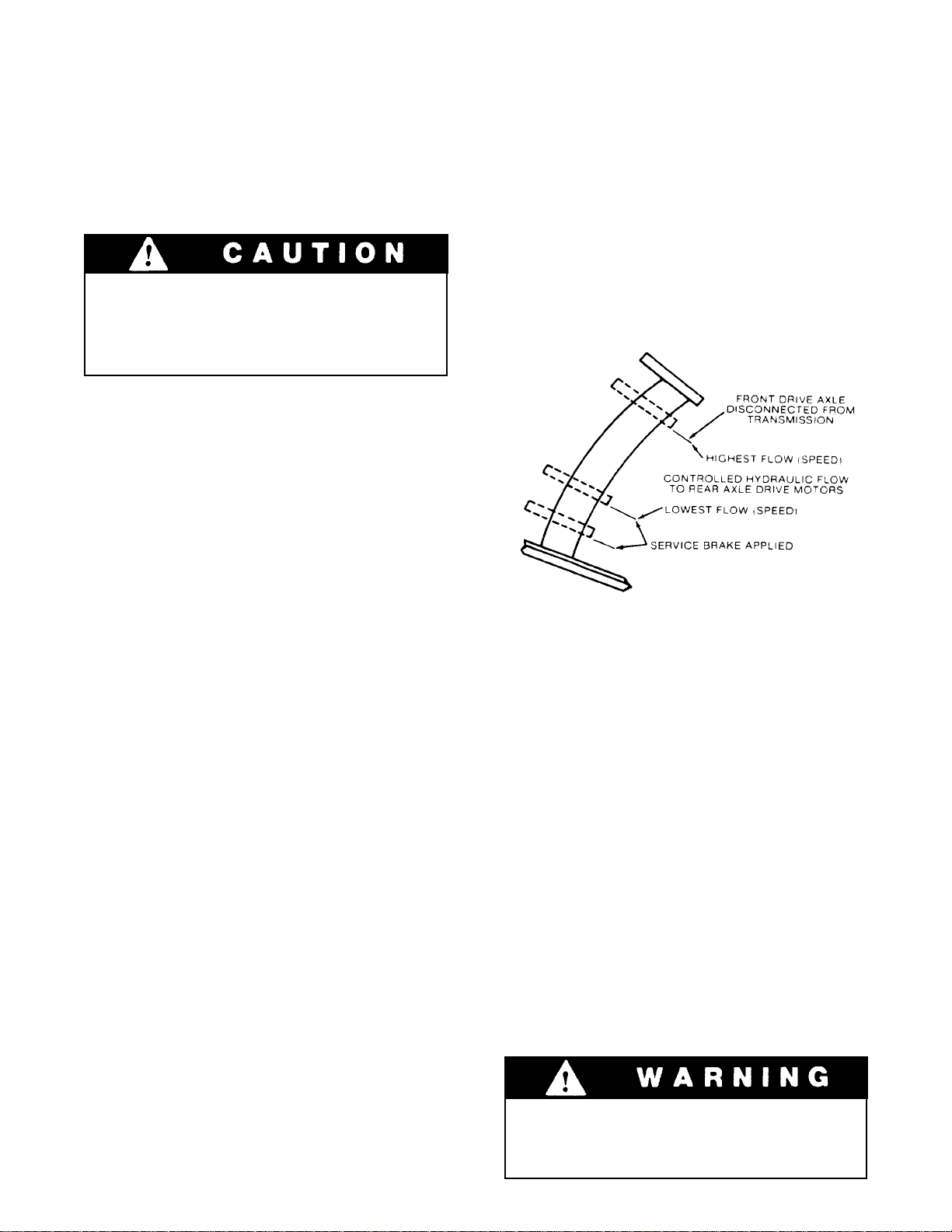
The service brake/inching pedal has three separate
It disconnects front drive axle from transmission.
1.
functions:
The service brake is applied to the front wheels of the
handler.
Oil for the brakes comes from the pilot circuit pump,
thru an accumulator charging valve and the accumulator. When the service/inching brake pedal is depressed far enough to actuate the brake valve, the
hydraulic oil flows to the wet disc brakes in both front
wheel hubs. The pressure compresses the brake discs.
It controls hydraulic flow to rear axle drive motors
2.
(hydraulic flow regulates speed).
It applies service brake.
3.
As illustrated, the three functions occur in sequence
as service brake/inching pedal is depressed from top
to bottom of stroke.
Parking Brakes
The parking brakes are also applied at the wet disc
brakes in the front axles.
TO APPLY THE PARKING BRAKE, pull up on the
parking brake knob located to the left of the operator’s seat. This opens the parking brake circuit to
dump, allowing a spring in the wet disc brake
assembly to compress the discs, applying the brakes.
TO RELEASE THE PARKING BRAKE, push down
on the parking brake knob.
When the handler is not being used, with the engine
shut off, the parking brakes must be applied.
Practice inching/braking in a safe, open
area until you are thoroughly familiar with
response of machine to pedal travel.
17
STEERING SYSTEM
Ninety degree rear wheel power steering is provided
to reduce operator fatigue and to permit high
maneuverability in close quarters.
Be alert for any increase in eftort needed to
steer. It any difference is noted, notify
maintenance personnel immediately for
correction. It power assist feature should
fail for any reason IT WOULD BECOME
VERY DIFFICULT TO STEER. For this
reason it is extremely important that you
NEVER TURN ENGINE OFF WHILE
TRAVELING.
In the event power steering tails, stop as
soon as possible. Do not drive unit until
problem has been corrected.
It is important that the operator practice
maneuvering the handler in a safe, open area until
he becomes thoroughly familiar with steering
response and clearance required for tailswing and
load when turning.
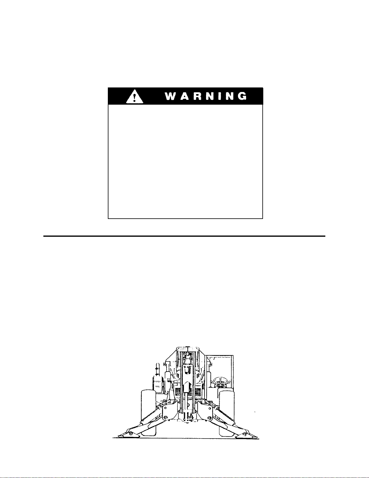
FRONT OUTRIGGERS (2) (OPTIONAL)
Front outriggers are provided in order to raise the
front tires off of the ground level while working, thus
improving the overall stability of the handler .
Two outrigger control levers are located to the right
hand side of the operator’s seat. Pushing forward on
the lever lowers the outriggers, and pulling back on
the lever raises them.
18
DRIVE TRAIN
General
The drive train provides two and four wheel drive
and includes the engine, torque converter
transmission, drive shaft and front and rear driving
axles.
Inching travel is directly related to drive train
functions and will be discussed in this section.
Two & Four Wheel Drive
The drive train is designed to provide two wheel
drive (front axle driving) or four wheel drive (both)
front and rear axles driving.
Under certain conditions, changing from four wheel
drive to two wheel drive may cause a difference in
the way the machine responds to steering, braking
and drive controls. Always be aware of which travel
mode you are using.
There are two ways to disengage rear wheel
drive:
Shift to third gear (rear axle drive is engaged only
1.
in first and second gears)
Disengage rear planetary hubs (refer to Rear
2.
Drive Axle heading in this section)
NOTE: Rear drive axle can also be disengaged in
response to overload in associated electrical
circuitry causing automatic reset type circuit
breaker to trip (open). Breaker will close again in
approximately ten seconds.
Torque Converter
There are no operator controls for the torque
converter. It functions automatically to permit
starting from a standstill in any transmission speed
range.
An oil temperature gage is provided to indicate
operating temperature of torque converter/transmission. Normal operating temperature is 180200°F. (82- 93°C.). If overheating occurs, attempt
to lower temperature by traveling in a lower gear. If
necessary, stop and allow torque converter to cool
with engine running and gear selector in neutral. Be
sure radiator fins are clean.
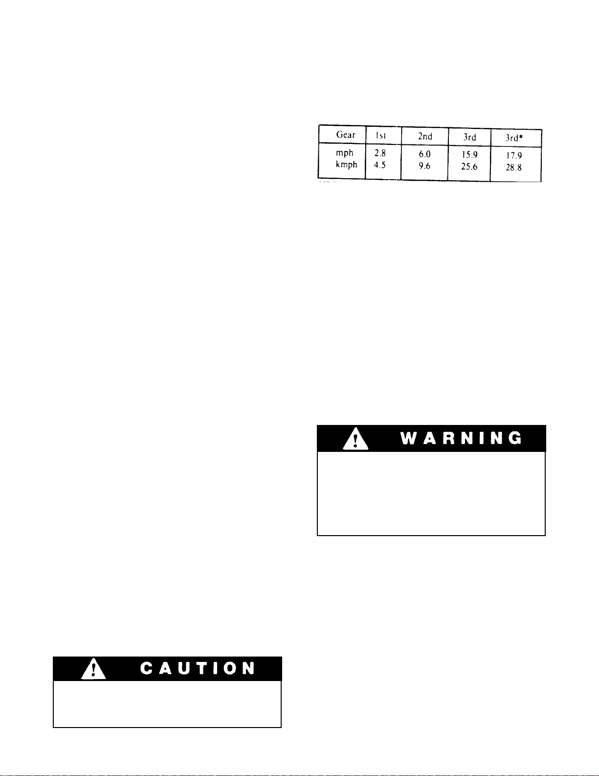
Transmission
The transmission provides three speed ranges for
both forward and reverse travel.
*With rear planetary hubs disengaged
There are three operator controls for the
transmission:
Gear Selector Lever (for 1st, 2nd and 3rd gears)
1.
2.
Direction Selector lever (for forward, neutral
and reverse)
3.
Service Brake Inching Pedal (refer to Inching
Travel heading in this section)
T o Operate Transmission:
1.
Release parking brake and hold handler in
position using service brake.
2.
Move gear selector to appropriate speed range
(1st. 2nd or 3rd gear). The gear selector may be
shifted while traveling. When traveling downhill,
use the same gear needed to travel up the hill.
Never shift gear selector or direction
selector to cause a sudden change of
travel speed or direction. Such a change
could cause load to shift or machine to tip
over. Reversing direction while traveling
can also damage transmission.
3.
Move direction selector to forward or reverse
position.
Release service brake and depress accelerator to
4.
attain appropriate speed.
5.
Stop handler by releasing accelerator and
applying service brake.
6.
Move direction selector to neutral position.
Continued operation of overheated torque
converter/transmission can cause serious
damage to these components.
Apply parking brake.
7.
Front Driving Axle
The front driving axle includes a differential and
planetary drive hubs and is powered by a drive shaft
from the transmission. The service brake/inching
pedal is the only operator control for the front axle
(refer to Inching Travel heading).
19
continued...
Rear Driving Axle
The rear driving axle includes planetary hubs which
are powered by hydraulic motors mounted on the
inner face of the hubs. HYdraulic flow to drive
motors is provided only in first and second gear
speed ranges. Drive motors are free-floating in third
gear.
Continuous driving for two miles or more
in third gear, with rear driving hubs
engaged, can damage hydraulic drive
motors.
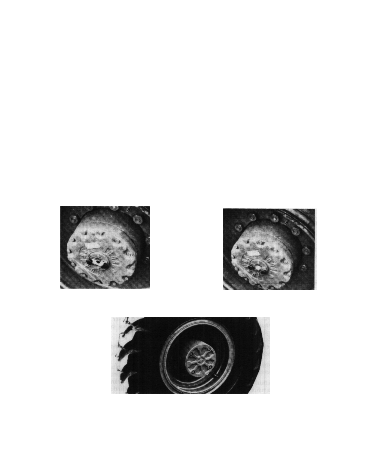
To Disengage Rear Driving Hubs:
Apply parking brake and remove key from
1.
ignition switch.
Remove thumb screws or hex head cap screws
2.
from keeper pin plate.
travel functions only in first and second gears. There
is no hydraulic flow to drive motors in third gear.
Inching travel is controlled by the service
brake/inching travel pedal. This pedal has three
separate functions:
It disconnects front drive axle from
1.
transmission.
It controls hydraulic flow to rear axle drive
2.
motors (hydraulic flow equals speed).
It applies service brake.
3.
Remove and rotate plate (cup out-engaged-cup
3.
in-disengaged).
Secure plate using thumb screws or hex head cap
4.
screws.
Repeat procedure for other hub.
5.
To Engage Rear Driving Hubs: Repeat procedure.
NOTE: If machine is moved with keeper pin plate
removed, input shaft pin will pop out.
Hydraulic flow to rear axle drive motors is
controlled electrically. An automatic reset type
breaker is included to prevent damage from
overload. If circuit breaker trips (opens) rear
axle drive will be inoperative for approximately
ten seconds until breaker resets. Notify
maintenance personnel if circuit breaker trips
repeatedly.
To determine whether circuit breaker has tripped,
attempt to move machine using inching travel. If
machine does not respond to inching travel pedal,
circuit breaker is open.
As illustrated, the three functions occur in sequence
as pedal is depressed from top to bottom of stroke.
To Engage Inching Travel:
Depress service brake/inching travel pedal
1.
approximately 1-1/2 inches to disengage front
driving axle from transmission. At this point rear
drive motors are receiving full flow and travel
speed will not have changed.
Continue to depress pedal to reduce speed-the
2.
more pedal travel, the less speed.
T o stop, depress pedal fully.
3.
OR
To resume normal travel release service brake/
inching travel pedal. Depress accelerator pedal to
attain appropriate speed.
Inching Travel
Inching travel is provided to permit very slow travel
while maintaining high engine speed for other
functions. Because inching travel depends on
hydraulic flow to rear axle drive motors, inching
Practice inching/braking in safe, open
area until you are thoroughly familiar with
response of machine to pedal travel.
20
MOVING HANDLER (Emergency Only)
If handler must be moved, when the engine is not
workable, extreme care should be used because:
1.
With the engine not operating there will be NO
steering.
2.
With the wheel hubs adjusted to permit movement, ther will be NO brakes.
If the handler is to be moved, do the following:
1.
Place blocks on wheels to prevent movement.
2.
On both rear axles, reverse the hub disengagement
caps.**
3.
Loosen front hub cover bolts equally until cover
moves 3/16" to 1/4". This released the wet disc
brakes. ***
We recommend that the unit be pushed, not towed
and that the unit be attached firmly to the pushing
vehicle because the handler brakes are released.
**In Disengaged **Out Engaged
** Back off 4 bolts
21
MATERIAL HANDLING
Leveling
The handler is designed to permit tilting main frame
eight degrees to left or right to compensate for
uneven ground conditions.
Raising the boom (loaded or unloaded)
when handler is leaning to the side can
cause machine to tip over with little or no
warning.
A level indicators located on upper portion of front
window frame to permit operator to determine that
machine is or is not level.
The rear axle pivots at the midpoint of the main
frame to help assure that wheels will remain in
contact with ground. A hydraulic cylinder provides
a rigid connection between front axle and main
frame to help assure a solid work platform and
permit tilting main frame to left or right.
NOTE:The frame leveling function is provided only
to level the machine before lifting or placing a load.
Do not attempt to use leveling feature to turn on or
travel across a slope.
To Level Handler:
Position machine in best location to lift or place
1.
load and apply brake.
Observe level indicator to determine whether
2.
machine must be leveled. Note position of
indicator for later realignment.
If necessary, position boom in carry position and
3.
move carriage tilt machine level lever to left or
right to level machine. Move lever to left to lower
left side of frame or move lever to right to lower
right side of frame.
Lift or place load as appropriate.
4.
Retract and lower boom to carry position.
5.
Realign frame to position noted in step 2.
6.
If handler cannot be leveled using leveling
system, do not attempt to raise or place
load. Have surface leveled.
Boom
The three section hydraulically operated boom
provides maximum reach of 36 feet above
horizontal at 70ø elevation and 21 feet forward of
forward edge of front tires at 0ø elevation (measured
to heel of standard forks mounted on standard
carriage). Boom travel extends from 4ø below
horizontal to 70ø above horizontal.
Raise boom by pulling boom lever to rear and lower
boom by pushing boom lever forward.
Boom extension and retraction is accomplished by a
hydraulic crowd cylinder anchored at rear of boom
section no. 1 and at front of boom section no. 2 and
also by a cable and push beam arrangement within
the boom sections. Extension or retraction of attachment
boom section no. 2 is always equaled by a
corresponding movement of boom section no.
3
A hydraulic cylinder is located within the boom
head to tilt the fork carriage or other attachment
back and forth as required.
The tilt cylinder is controlled by carriage tilt/
machine level lever. Push lever forward to tilt
attachment down or pull lever to rear to tilt
attachment up.
Extend boom by moving boom lever to right and
retract boom by moving boom lever to left.
A compensating cylinder is pinned to main frame
and to base of boom section no. 1. As boom is
raised, oil is transferred from rod end of
compensating cylinder to rod end of attachment tilt
cylinder. Lowering boom causes transfer of oil from
barrel end of compensating cylinder to barrel end of
attachment tilt cylinder. This transfer of oil causes
extension and retraction of tilt cylinder to maintain
angle of attachment as boom is raised and lowered.
All cylinders related to boom (attachment tilt, raise/
lower and extend/retract) are protected by pilot
operated check valves which prevent load from
falling in event of a broken hydraulic hose or tube.
22
Attachments
Although the carriage/fork combination is most
frequently used, a number of other attachments
available for use with the handler. 180ø and 100ø
swing forks are available. A material bucket can be
provided for light duty work. A truss boom is
available to extend maximum reach and height and
can be fitted with a winch when required. Consult
your Gradall Material Handler Dealer for information on attachments designed to solve special
material handling problems.
Attachments Capacities
The Rated Capacity Chart located on left side of
dashboard indicates maximum capacities for
handlers equipped with standard carriage/fork
combination. These capacities apply only to
standard carriage, fork combination and cannot be
used for other attachments.
A serial number plate Is attached to all attachments
and indicates maximum capacity for that
attachment. However, the capacity shown on
this plate may be incorrect in relation to your
machine.
Refer to Attachment Capacity Plate located below
Serial Number Plate on right cab wall for correct
maximum capacity for all attachments furnished
with your machine. If attachment in question is not
listed on this plate contact factory for maximum
capacity.
Refer to Operating Procedures and Techniques
section for instructions on proper use of
information shown on capacity plates.
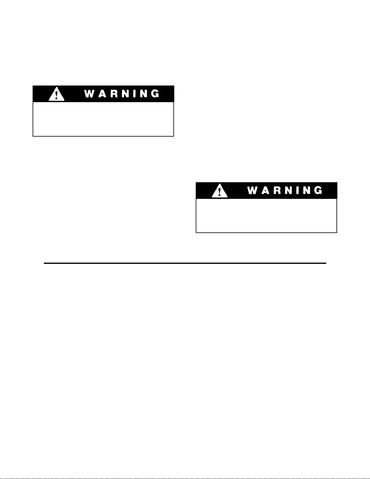
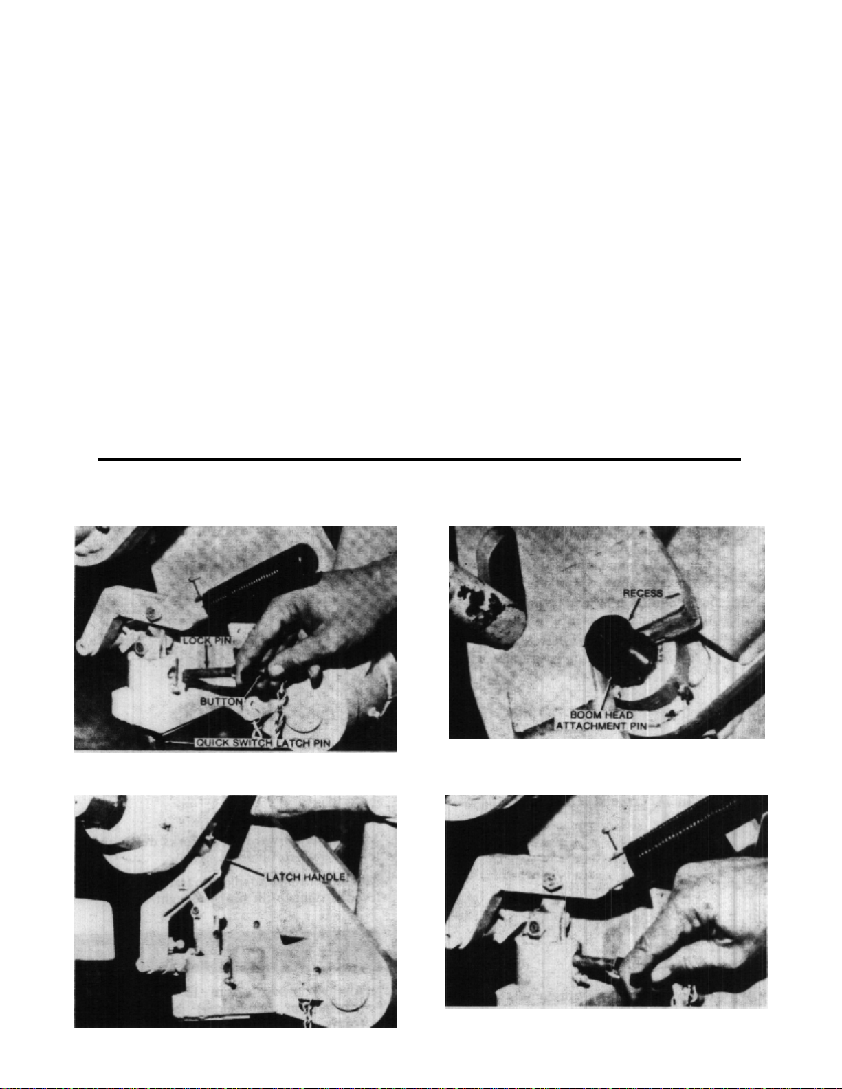
Attachment Installation
1.
Depress button and remove lock pin from quick
switch latch pin.
Position boom head attachment pin fully in recess
3.
of attachment. Tilt upward slightly to assure full
engagement.
2.
Raise handle to retract latch pin fully .
23
4.
Depress handle fully to engage latch pin in
attachment and install lock pin in latch.
OPERATING PROCEDURES & TECHNIQUES
This section highlights some common procedures
and discusses areas which may be new to even the
experienced operator.
Hydraulic Controls
All boom and attachment movements are governed
by hydraulic controls. Rapid, jerky operation of
hydraulic controls will cause rapid, jerky movement
of the load. Such movements can cause the load to
shift or fall or may cause the machine to top over.
Feathering
Feathering is a control operation technique used for
smooth load handling. To feather controls, move
control lever very slowly until load begins to move,
then gradually move lever further until load is
moving at desired speed. Gradually move lever
toward neutral as load approaches destination.
Continue to reduce load speed to bring load to a
smooth stop. Feathering effect can be increased by
lowering engine speed at beginning and near end of
load movement.
With boom raised above horizontal, forks can be
removed from a load by moving boom control lever
back and to the left until forks move rearward
horizontally.
With boom lowered below horizontal, forks can be
inserted under a load by moving boom control lever
back and to the right until forks move forward
horizontally.
With boom lowered below horizontal, forks can be
removed from a load by moving boom control lever
forward and to the left until forks move rearward
horizontally.
The closer the boom to horizontal, the less boom
raise/lower movement required for inserting and
removing forks.
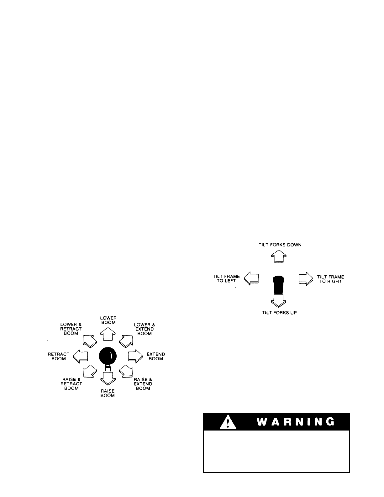
Carriage Tilt/Machine Level Lever
Boom Control Lever
The boom control lever can be positioned to cause
individual boom movements or combinations of
boom movements as illustrated.
Move lever to left to the tilt forks down and move
lever to rear to tilt forks up.
Move lever to left to tilt main frame to left and move
lever to right to tilt frame to right.
With boom raised above horizontal, forks can be
inserted under a load by moving boom control lever
forward and to the right until forks move forward
horizontally.
Always move boom to carry position
(horizontal or below before leveling
frame. Attempting to level machine with
boom raised may caused it to tip over.
24
Loading...