

Gradall LOED-534A Service Manual

®
LOED MATERIAL HANDLER
MODEL 534A
Service Manual
PART NO. 9020-5896
This manual describes the LOED Handler as origionally
designed and built by the LOED Corporation. The LOED
Handler product line was purchased October 15, 1982 by
The Warner & Swasey Co., a subsidiary of The Bendix
Corporation. Descriptions and specifications shown herein
are subject to change without notice.
READ AND UNDERSTAND THIS MANUAL
BEFORE STARTING, OPERATING OR
PERFORMING MAINTENANCE PROCEDURES
ON THIS MACHINE.
KEEP THESE MANUAL IN CAB
Gradall is a registered trademark for hudraulic
excavators built by The Gradall Co.
IMPORTANT
THE
COMPANY
406 MILL AVENUE S.W.
NEW PHILADELPHIA, OHIO 44663
(216) 339-2211

CONTENTS
Service/replacement parts . . . . . . . . . . . . . . . . . . . . . . . . . . . . . . . . . . . . . . . . . . . . . . . . . . . . . . . . . . . . .
Capacity . . . . . . . . . . . . . . . . . . . . . . . . . . . . . . . . . . . . . . . . . . . . . . . . . . . . . . . . . . . . . . . . . . . . . . .
Nomenclature . . . . . . . . . . . . . . . . . . . . . . . . . . . . . . . . . . . . . . . . . . . . . . . . . . . . . . . . . . . . . . . . . . . .
Retraction chain replacement . . . . . . . . . . . . . . . . . . . . . . . . . . . . . . . . . . . . . . . . . . . . . . . . . . . . . . . . . . .
Extension chain replacement . . . . . . . . . . . . . . . . . . . . . . . . . . . . . . . . . . . . . . . . . . . . . . . . . . . . . . . . . . .
Boom hose replacement . . . . . . . . . . . . . . . . . . . . . . . . . . . . . . . . . . . . . . . . . . . . . . . . . . . . . . . . . . . . . .
Shift control adjustment . . . . . . . . . . . . . . . . . . . . . . . . . . . . . . . . . . . . . . . . . . . . . . . . . . . . . . . . . . . . . .
Brake adjustment . . . . . . . . . . . . . . . . . . . . . . . . . . . . . . . . . . . . . . . . . . . . . . . . . . . . . . . . . . . . . . . . . .
Tire and rim repair . . . . . . . . . . . . . . . . . . . . . . . . . . . . . . . . . . . . . . . . . . . . . . . . . . . . . . . . . . . . . . . . . .
Parking brake repair . . . . . . . . . . . . . . . . . . . . . . . . . . . . . . . . . . . . . . . . . . . . . . . . . . . . . . . . . . . . . . . . .
Power master cylinder repair . . . . . . . . . . . . . . . . . . . . . . . . . . . . . . . . . . . . . . . . . . . . . . . . . . . . . . . . . . . .
Planetary hub repair . . . . . . . . . . . . . . . . . . . . . . . . . . . . . . . . . . . . . . . . . . . . . . . . . . . . . . . . . . . . . . . . .
Hydraulic pressure adjustment . . . . . . . . . . . . . . . . . . . . . . . . . . . . . . . . . . . . . . . . . . . . . . . . . . . . . . . . . .
Hydraulic cylinder repair . . . . . . . . . . . . . . . . . . . . . . . . . . . . . . . . . . . . . . . . . . . . . . . . . . . . . . . . . . . . . .
Valve repair . . . . . . . . . . . . . . . . . . . . . . . . . . . . . . . . . . . . . . . . . . . . . . . . . . . . . . . . . . . . . . . . . . . . . .
Pump and motor troubleshooting . . . . . . . . . . . . . . . . . . . . . . . . . . . . . . . . . . . . . . . . . . . . . . . . . . . . . . . . .
Pump repair . . . . . . . . . . . . . . . . . . . . . . . . . . . . . . . . . . . . . . . . . . . . . . . . . . . . . . . . . . . . . . . . . . . . . .
Rear motor repair . . . . . . . . . . . . . . . . . . . . . . . . . . . . . . . . . . . . . . . . . . . . . . . . . . . . . . . . . . . . . . . . . .
Front motor repair . . . . . . . . . . . . . . . . . . . . . . . . . . . . . . . . . . . . . . . . . . . . . . . . . . . . . . . . . . . . . . . . . .
Bolt torque chart . . . . . . . . . . . . . . . . . . . . . . . . . . . . . . . . . . . . . . . . . . . . . . . . . . . . . . . . . . . . . . . . . . .
Hydraulic fitting torque chart . . . . . . . . . . . . . . . . . . . . . . . . . . . . . . . . . . . . . . . . . . . . . . . . . . . . . . . . . . .
Electrical schematic . . . . . . . . . . . . . . . . . . . . . . . . . . . . . . . . . . . . . . . . . . . . . . . . . . . . . . . . . . . . . . . . .
Hydraulic schematic . . . . . . . . . . . . . . . . . . . . . . . . . . . . . . . . . . . . . . . . . . . . . . . . . . . . . . . . . . . . . . . .
Hydraulic component location . . . . . . . . . . . . . . . . . . . . . . . . . . . . . . . . . . . . . . . . . . . . . . . . . . . . . . . . . . .
Parts section - contents . . . . . . . . . . . . . . . . . . . . . . . . . . . . . . . . . . . . . . . . . . . . . . . . . . . . . . . . . . . . . .
3
4
5
6
8
10
11
12
13
18
20
24
29
30
32
44
45
55
74
84
85
86
89
93
95
1

GENERAL INFORMATION
IMPORTANT SAFETY NOTICE
Safe operation depends on reliable equipment and proper operating
procedures. Performing the checks and services described in this manual will
help to keep your Gradall Handler in reliable condition and use of the
recommended operating procedures can help you avoid accidents. Because
some procedures may be new to even the experienced operator we recommend
that this manual be read, understood and followed by all who operate the unit.
Danger, Warning and Caution notes in this manual will help you avoid injury
and damage to the equipment. These notes are not intended to cover all
eventualities; it would be impossible to anticipate and evaluate all possible
applications and methods of operation for this equipment.
Any procedure not specifically recommended by The Gradall Division must be
thoroughly evaluated from the standpoint of safety before it is placed in
practice. If you aren’t sure, contact your Gradall Distributor before operating.
Do not modify this machine without written permission from the Gradall
Division.
NOTICE
The Gradall Division retains all
proprietary rights to the information
contained in this manual.
The Company also reserves the right to
change specifications without notice.
2
MODEL 534A LOED HANDLER

SER VICE
Your LOED Handler distributor is properly equipped to service your LOED Handler.
Repairs should be made by trained and qualified service personnel only.
CAUTION: Do not attempt to
repair your machine unless
you are trained and qualified
to do so.
Modifications must not be made unless prior approval has been obtained from LOED
Corporation. Your distributor has the necessary forms to request authorization
for specific modifications.
CAUTION: Do not modify your
prior approval of LOED Corporation. The safety and reliability
of your machine may be affected
by improper modification.
REPLACEMENT P AR TS
Replacement parts can be ordered from your nearest LOED Handler distributor.
Always furnish the machine model and serial number as well as a complete description
of the part and the part number. This enables the distributor to quickly and
accurately fill your order.
NOTE: For a safer more dependable machine, use only factory approved parts.
3

MODEL 534
6,000# Capacity
FIGURE 1
4

NOMENCLA TURE
FIGURE 2
FORKS
1.
FORK FRAME
2.
BOOM HEAD
3.
TIL T CYLINDER
4.
THREE SECTION BOOM
5.
LIFT CYLINDER
6.
COMPENSA TING CYLINDER
7.
HYDRAULIC RESERVOIR
8.
FUEL T ANK
9.
PLANET ARY HUB
10.
CROWD CYLINDER
11.
LEVEL CYLINDER
12.
5

RETRACTION CHAIN REPLACEMENT
DISSASSEMBLY
Retract boom completely.
1.
Remove rear boom cover.
2.
Remove extension (large) chain adjusting nut and jam nut.
3.
Remove hose retainer nuts and jam nuts. Disconnect hoses.
4.
Remove bolts holding hose guide pan to front of strongback.
5.
Remove strongback.
6.
Unpin retraction (small) chain from chain ears at back of third
7.
section.
8.
Unpin retraction chain from section one ears (access hole in
9.
bottom of section).
Pull chain out back of boom.
REASSEMBLY
Note: Replace chain ends whenever chain is replaced.
1.
Use fish wire to pull new chain from back of boom to ears in
bottom of section one.
2.
Lay chain over sheave and pin to back of section three.
3.
Reinstall strongback. Use LOCTITE 242 (blue-medium strength)
4.
on all bolts and torque to specification.
5.
Bolt hoseguide pan to strongback.
Reconnect extension chain. With crowd cylinder fully retracted,
tighten extension chain until there is no slack in retracting
chain. Install jam nut.
6.
Reconnect hoses and hose retainers.
7.
Reinstall rear boom cover.
6
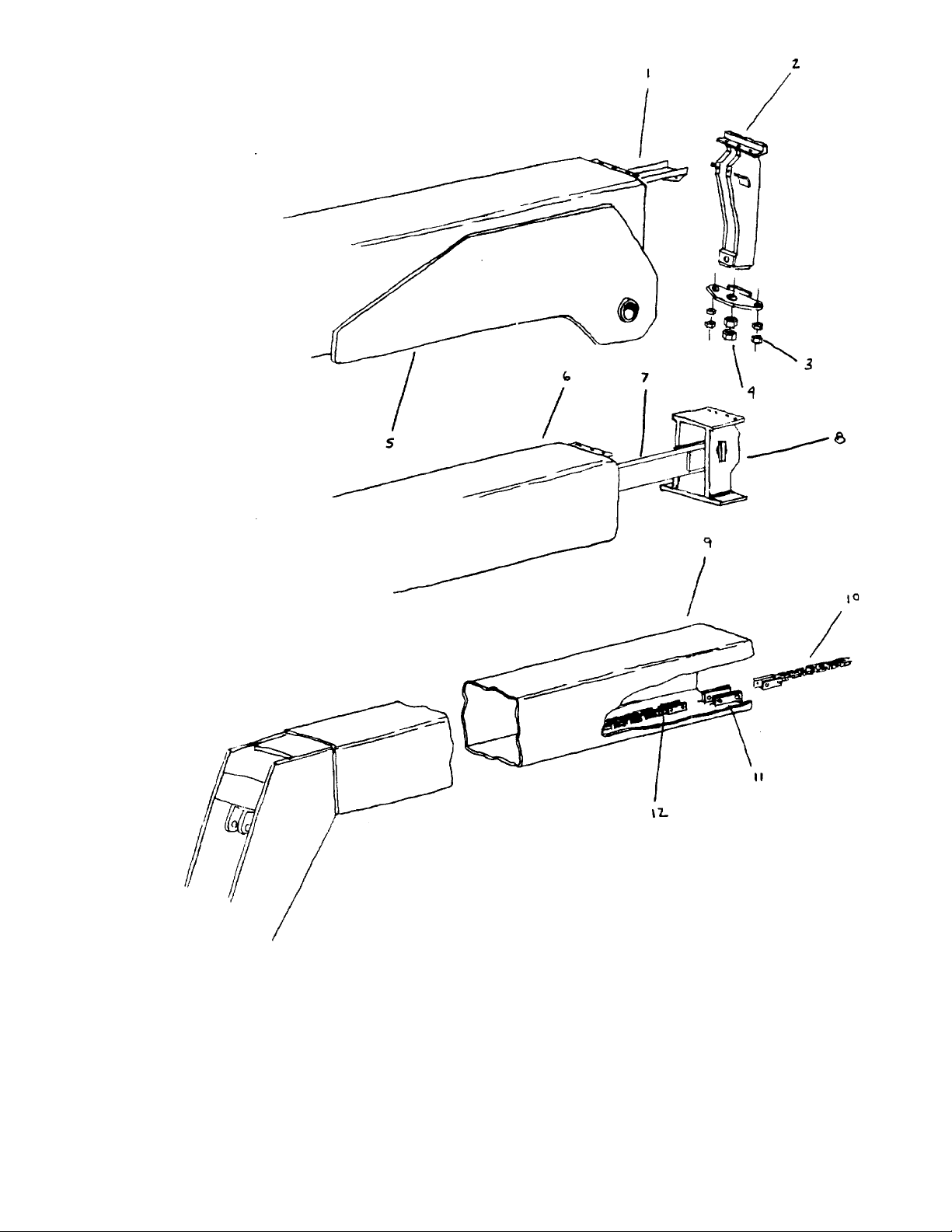
FIGURE 3
Guide Pan
1.
Strongback
2.
Hose Retainer Nuts
3.
Extension Chain Nuts
4.
Section One
5.
Section Two
6.
T ake-up Beam
7.
T ake-up Beam Bracket
8.
Section Three
9.
Retraction Chain
10.
Section Three Chain Ears
11.
Extension Chain
12.
7

EXTENSION CHAIN REPLACEMENT
DISSASSEMBLY
1.
Retract boom completely .
2.
Remove rear boom cover.
3.
Remove extension (large) chain adjusting and jam nuts.
4.
Remove hose retainer and jam nuts. Disconnect hoses.
5.
Remove bolts holding hose guide pan to front of strongback.
6.
Remove strongback.
7.
Unpin retraction (small) chain from chain ears at back of third section.
Allow chain to lie on bottom of 1st section.
8.
Unbolt take-up beam bracket from back of section two. Pull beam and
hose guide pan out back of boom.
9.
Unpin extension chain from ears at back of section three.
REASSEMBLY
Note: Replace chain ends whenever chain is replaced
1.
Pin extension chain to ears at back of section three.
2.
Lay chain and hoses in hose guide pan.
3.
Carefully slide take-up beam and guide pan into boom allowing chain
and hoses to roll over sheaves at front of beam.
4.
Bolt take-up beam bracket into back of section two.
Note: Use LOCTITE 242 (blue-medium strength) on all bolts and
torque to specification.
5.
Pin retraction chain to ears on back of section three.
6.
Reinstall strongback.
7.
Bolt hose guide pan to strongback.
8.
Reconnect extension chain. W ith crowd cylinder fully retracted,
tighten extension chain until there is no slack in retraction
chain.
9.
Reconnect hoses and hose retainers.
10.
Reinstall rear boom cover.
8

FIGURE 4
Guide Pan
1.
Strongback
2.
Hose Retainer Nuts
3.
Extension Chain Nuts
4.
Section One
5.
Retraction Chain
6.
Retraction Chain Ears - Section 1
7.
Section Three
8.
Retraction Chain Ears - Section 3
9.
9

BOOM HOSE REPLACEMENT
IF HOSE IS INT ACT
Remove rear boom cover.
1.
Disconnect hose retainer and remove tensioning spring.
2.
Connect new hose to old hose with short length of steel wire.
3.
Disconnect old hose at back of section three. Carefully pull
4.
new hose along guide pan and around reel while pulling old hose
out back of boom.
Connect new hose to tube line at rear of section three.
5.
Reassemble hose retainer and reinstall. Connect hose.
6.
Replace rear boom cover.
7.
IF HOSE IS BROKEN
Follow dissassembly procedure outlined in “Extension Chain Replacement”
through step 8. Replace hose and reassemble.
10

SHIFT CONTROL LINKAGE ADJUSTMENT
Put shift control in 1st gear.
1.
Adjust valve linkage (A) so micro switch (B) is actuated
2.
with spool pulled down to stop.
Adjust linkage (C) so movement of lever from 1-2 and 3-4
3.
moves spool from full down to full up.
Adjust linkage (D) so spool moves from full back to full
4.
forward as lever is moved from 2-3.
Repeat 1 thru 4 as necessary to get smooth shifting action.
5.
FIGURE 5
11
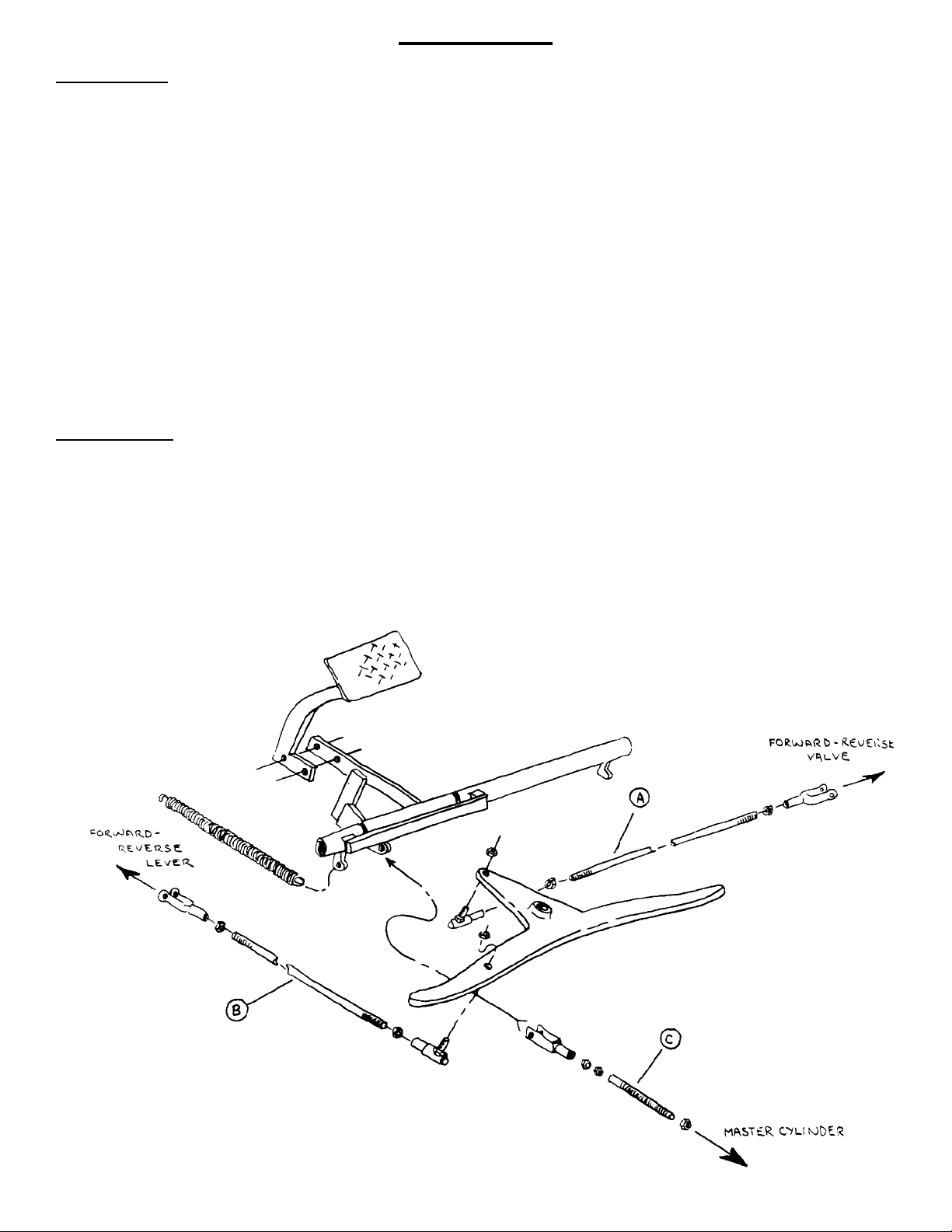
BRAKE ADJUSTMENT
SER VICE BRAKE
Note: Prior to any brake adjustment the forward-reverse linkage
must be adjusted as follows:
With the forward-reverse lever in neutral, adjust
1.
linkage rod “A” so that “B” to “B1” and “C” to “C1”
are of equal length, with the forward-reverse valve
spool in its neutral position (linkage rod “D” may
have to be adjusted to reach alignment).
2.
With the forward-reverse lever in forward, depress
brake pedal until all slop is taken up in the brake
linkage. At that point the spool in the forwardreverse valve should be 1/8" out of the neutral
position. If not, adjust brake linkage compression
spring “E” to reach that point.
P ARKING BRAKE
1.
The spring-apply/hydraulic release brake requires
no adjustment.
2.
On machines with mechanical brake calipers, adjust
both sides so the pads nearly touch the disc when
the lever is in the off position.
FIGURE 6
12

TIRE and RIM SER VICING SAFETY
IMPORTANT
For safety’s sake, always remove the valve core and exhaust all air from a
single tire and from both tires of a dual assembly prior to removing any
rim components, or any wheel components, such as nuts and rim
clamps.
Check the valve stem by running a piece of wire through the stem to
make sure it Is not plugged
GENERAL:
Do not mount or demount tires without
!
proper training. Follow all procedures and
safety instructions. Wall charts containing
mounting and demounting instructions for
all Goodyear on-highway rims are available through your Goodyear rim supplier.
Ask for “ON-HIGHWAY RIM MOUNTING AND DEMOUNTING CHART SET
NO. TR71-2042". This set contains five
charts covering all Goodyear on-highway
rims.
!
“MULTIPIECE RIM/WHEEL MATCHING CHARTS” are available through
Motor Wheel Corporation and the United
States Department of Transportation
(DOT), W ashington, D.C.
DEMOUNTING:
Always exhaust all air from a single tire
!
and from both tires of a dual assembly
prior to removing any rim components or
any wheel components such as nuts and
rim clamps.
!
Make sure to remove valve core to exhaust all air from the tire. Remove both
cores from a dual assembly.
INSPECTION:
!
Clean rims and repaint to stop detrimental effects of corrosion and facilitate
checking and tire mounting. Be very careful to clean all dirt and rust from the lock
ring and gutter. This is important to
secure the lock ring in its proper position.
A filter on the air inflation equipment to
remove the moisture from the air line
helps prevent corrosion. The filter should
be checked periodically to see that it is
working properly.
!
Check rim components periodically for
cracks. Replace all cracked, badly worn,
damaged and severely rusted components
with new parts of same size and type.
When in doubt replace.
!
Do not, under any circumstances, attempt
to rework, weld, heat, or braze any rim
components that are cracked, broken, or
damaged. Replace with new parts or parts
that are not cracked, broken, or damaged
and which are of the same size and type.
!
Make sure correct parts are being assembled. Check DOT chart, your distributor
or the manufacturer if you have any
doubts.
Check the valve stem by running a piece of
!
wire through the stem to make sure it is
not plugged.
13
!
Don’t be careless or take chances. If you
are not sure about the proper mating of
rim and wheel parts, consult a rim and
wheel expert. This may be the tire man
who is servicing your fleet, the rim and
wheel distributor in your area, or the
Motor Wheel sales engineer.

Mixing parts of one type rim with those of
!
another is potentially dangerous. Always
check DOT chart or manufacturer for
approval.
!
Don’t reinflate a tire that has been run flat
without first inspecting the tire, tube,
flap, rim and wheel assembly. Double
check the side ring, flange, bead seat, lock
ring and “O” ring for damage and make
sure that they are secure in the gutter
before inflation.
MOUNTING AND INFLATION:
!
Don’t try to seat rings or other components by hammering while tire is inflated
or partially inflated.
Double check to make sure all components
!
are properly seated prior to inflation.
Inflate in a safety cage or use safety chains
during inflation.
!
Don t inflate tire before all components
are properly in place. Place in safety cage
and inflate to approx. 10 psi, recheck components for proper assembly. If assembly
is not proper, deflate and correct. Never
hammer on an inflated or partially inflated
tire rim assembly. If assembly is proper
at approx. 10 psi, continue to inflate to
fully seat the tire beads. Then completely
deflate the tire to prevent localized over
stretching of tube. Reinflate to recommended operating pressure.
!
Never sit on or stand in front of a tire and
rim assembly that is being inflated. Use a
clip on chuck and make sure inflation hose
is long enough to permit the person inflating the tire to stand to the side of the tire,
not in front or in back of the tire assembly.
!
Follow tire and rim manufacturer’s recommended mounting, demounting inflating and deflating procedures for tires and
rims.
Don’t hammer on rims or components with
!
steel hammers. Use rubber, lead, plastic or
brass faced mallets if it is necessary to tap
components together.
SERVICING TIRE AND RIM
ON VEHICLE:
!
Don’t try to drive an assembled or partially assembled tire and rim over a cast
spoke wheel by hammering. Stop - deflate
and examine to determine the reason for
the improper fit. Look for distortion or to
components that are not properly locked
or seated.
Block the tire and wheel on the opposite
!
side of the vehicle before you place the
jack in position.
!
Regardless of how hard or firm the ground
appears, put hardwood blocks under the
jack. Always crib up vehicle with blocks
just in case the jack should slip.
OPERATION:
Don’t use undersized rims. Use recommended rim for tire. Check Goodyear/
Motor Wheel catalogs for proper tire/rim
matching.
!
Don’t overload or over-inflate tire/rim
assemblies. Check your rim manufacturer
if special operating conditions are
required.
!
Never run a vehicle on one tire of a dual
assembly. The carrying capacity of the
single tire and rim is dangerously exceeded and operating a vehicle in this
manner can result in damage to the rim
and tire.
ADDITIONAL NOTES APPLYING
TO EARTHMOVER RIMS:
!
Use caution when removing heavy earthmover rim components. Use mechanical
aids. This will help protect you from
injury.
!
Demounting tools apply pressure to rim
flanges to unseat tire beads. Keep your
fingers clear. Always stand to one side
when you apply hydraulic pressure (if
the tool slips off, it can fly with enough
force to cause severe bodily injury or
death).
When using a cable or chain sling, stand
!
clear; it might snap and lash out.
!
Never attempt to weld on an inflated tire/
rim assembly or on a rim assembly with a
deflated tire.
!
Wall charts containing mounting and demounting instructions for all Goodyear
off-highway rims are available through
your Goodyear rim supplier. Ask for
“OFF-HIGHWAY RIM MOUNTING AND
DEMOUNTING CHART SET NO
EM73-2154". This set contains four charts
covering all Goodyear off-highway rims.
13

TWO-PIECE RIMS
Correct
FIGURE 7
The components in a correctly assembled and locked
two-piece rim fit snugly.
THREE-PIECE RIMS
Correct
Incorrect
FIGURE 9
An incorrectly assembled two-piece rim could have a large
gap in side ring. Components are not firmly locked in place.
DO NOT INFLATE TIRE AND RIM ASSEMBLY UNTIL
COMPONENTS ARE PROPERLY SEATED AND LOCKED.
Incorrect
FIGURE 8
A three piece rim that is correctly assembled has firmlyfitted components: lock ring gap is small with lock ring com-
pletely embedded in its cavity.
Side ring is seated in
gutter hook.
Correct
FIGURE 10
An incorrectly assembled three-piece rim. Lock ring is not
seated. DO NOT INFLATE UNTIL LOCK RING IS PROPERL Y
SEATED AND LOCKED.
KW, KB, KWX TYPE RIMS
KW, KB, and KWX type rims have
unique configurations that deserve
special mention. Make sure your
assembly pattern matches that
shown in photographs of correctly
assembled rims. DO NOT INFLATE
UNTIL ALL RIM COMPONENTS ARE
PROPERL Y LOCKED AND SEA TED.
FIGURE 11
Incorrect
Side ring is not seated in
gutter hook. Check for
incomplete assembly or
worn rim. Do not inflate
tire.
Rim ends match; rim
locking device is securely
locked.
Rim base is not locked.
One raised end of rim
end means incorrect
assembly or bent rim. Do
not inflate tire.
FIGURE 12 FIGURE 13
15

Replace Worn, Rusted & Corroded
Rim Parts
Replace Distorted Rims &
Components
Badly worn, rusted and corroded rims and components are
dangerous and should be replaced with new
parts.
Such hazards prevent proper fit of components, and can
cause difficult tire mounting.
Distorted rims and components will not properly lock
together. They should be replaced.
This hazard, besides making the tire/rim assembly unsafe
through improper fit, may cause difficult tire mounting.
FIGURE 14
Replace Cracked & Broken
Rims and Components
FIGURE 15
Fatigue-cracked or broken rims and components must be
replaced. Periodically inspect all rims and components for
signs of fatigue cracks or breakage.
FIGURE 16
16
WARNING!
MISMATCHED RIM PARTS ARE DANGEROUS
AND COULD CAUSE SEVERE INJUR Y
Most highway rims look alike, but all vary somewhat in
certain design features. It is these differences between
rims of different types that makes “part-mixing” a
hazardous business. A close, proper fit between rim parts
is essential to long tire life as well as to operating safety.
Very often. side-rings, flanges and lock-rings of different
types appear to be properly seated, but actually wide gaps
NOTE: Contact Motor Wheel Corp. for list of components that are designed to interchange with components of
other manufacturers. Department of Transportation (DOT) charts show rim interchangeability.
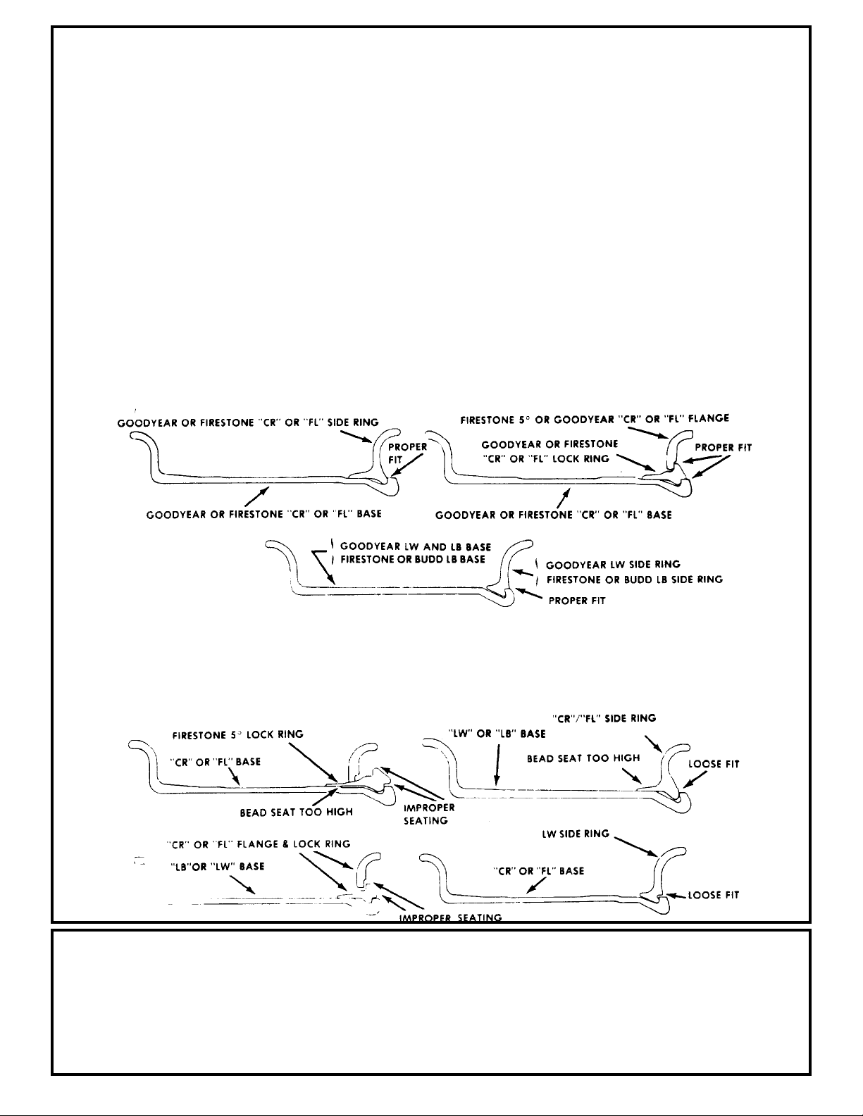
CORRECT
FIGURE 17
Goodyear “CR” and “FL” bases and components interchangeable with Firestone “CR” and “FL”. Goodyear “LB”
bases and components interchangeable with Firestone and Budd “LB”.
are present, frequently difficult to see. The rim
cross-sections below show correct, safe matchings of rim
parts as well as mismatched rings and bases which
almost always create an unsafe operating condition. The
pictures contained herein are intended only to depict some
examples of incorrect procedures. They are not intended to
show all incorrect and dangerous methods.
FIGURE 18
INCORRECT
IMPROPER RIM SELECTION CAN CAUSE
THESE TIRE AND TUBE OPERATING PROBLEMS
!
TIRE SLIPPAGE
!
TUBE PINCHING
!
V AL VE STEM TEAR OUTS
!
PL Y SEP ARATION
17
!
EXCESSIVE FLEXING
!
OVERHEA TING
!
SIDEWALL FAILURES
!
BLOWOUTS

P ARKING BRAKE
FUNCTION
The Parking Brake is spring loaded to apply the brake. Hydraulic pressure is used
to release or hold “off” the brake.
DISSASSEMBLY PROCEDURE
Loosen 2 bolts (22) alternately.
1.
Separate power plate (18) assembly from the remainder of the brake.
2.
Remove O-ring (5).
3.
Remove rotating disc (10) from splined shaft (7), remove springs (12) and
4.
stationary disc (11) from pins (8).
Repeat until all rotating discs (10), stationary disc (ll) and springs (12)
5.
are removed.
Remove primary disc (9).
6.
Remove pins (8).
7.
Remove springs (6) from counter bores.
8.
9.
Further disassembly of the seal (1), snap ring (2), bearing (3), and shaft
(7), from the housing (4) is not recommended, and should not be attempted
unless necessary for the replacement of specific parts.
10.
Remove seal (1). The seal will be damaged during removal and must be
replaced.
Remove retaining ring (2).
11.
Remove shaft (7) and bearing (3) by lightly tapping the shaft with a plastic
12.
mallet.
Remove shaft from bearing by supporting the inner race of the bearing and
13.
pressing the shaft out of the race.
Remove the piston (13) from the power plate (18) by introducing low pressure -.
14.
air - 15 psi - into the hydraulic inlet. Make sure piston is directed
away from the operator.
Remove O-rings (15,17) and teflon back-up rings (14,16) from the O. D. and
15.
I. D. ring grooves. Removal of the teflon back-up rings (14,16) may cause
damage to the teflon rings and should not be attempted unless necessary.
16.
Remove snap ring (20).
17.
Remove bearing (21) by tapping lightly with a plastic mallet.
ASSEMBLY PROCEDURE
Use the reverse of dissassembly with the following note and additions:
Worn O-rings and damaged or worn teflon back-up rings must be replaced
1.
prior to reassembly.
Cylinder of the power plate, piston and O-rings must be clean prior to
2.
assembly, and pre-lubed with system hydraulic fluid.
Assemble piston (13) into power plate (18) using a shop press, being careful
3.
not to damage the O-rings or the teflon back-up rings. Visually align the
center of the cut-outs in the piston (13) with the torque pin (8) holes in
the power plate (18).
Rotating discs must be clean and dry. There should be no pressure of oil
4.
on any lining material or mating surfaces of the stationary discs.
Alternately tighten bolts (22) and torque them to 75-85 lb. ft.
5.
18

FIGURE 19
19
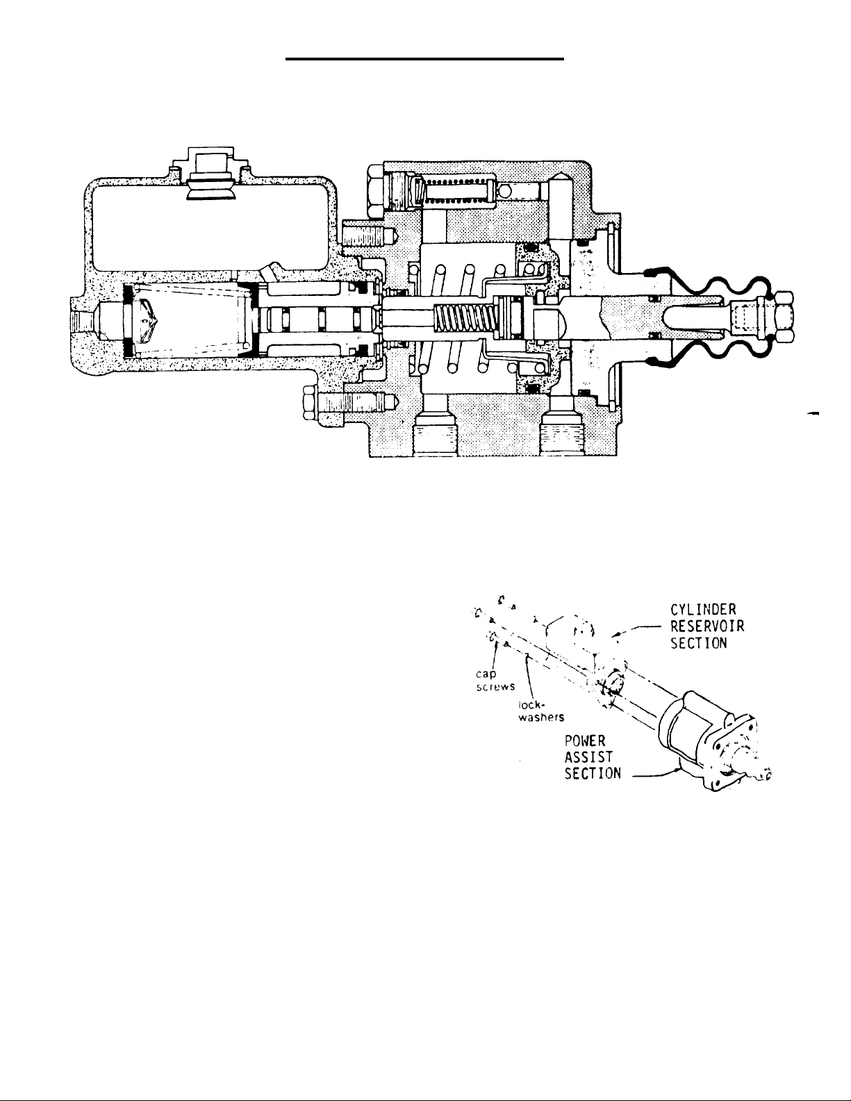
POWER BRAKE MASTER CYLINDER REP AIR
FIGURE 20
1.0 REMOVING BRAKE VALVE FROM VEHICLE AND
SEPARATlNG CYLINDER RESERVOIR SECTION
FROM POWER ASSIST SECTION. Refer to
Figures 20 & 21.
1.1 Remove Brake Valve from vehicle by dis-
connecting necessary fluid lines, disconnecting push rod, and removing
mounting bolts. Drain fluid from
assembly.
1.2 Separate Cylinder Reservoir Section from
Power Assist Section by removing three
cap screws and three lock-washers.
FIGURE 21
20

CYLINDER RESER VOIR SECTION
DISASSEMBLY OF CYLINDER RESERVOIR SECTION. Refer to Figures 1 & 3.
2 . 0
Drain fluid from unit before disassembling.
2 . 1
Remove retainer ring (item 1) from housing (item 14). CAUTION: Retainer ring
2 . 2
is under tension of spring (item 11).
Remove assembly (item 17) from cylinder bore.
2 . 3
Remove cup (item 9), retainer (item 10), spring (item 11), check valve (item 12),
2 . 4
and seat (item 13) from housing.
Remove filler cap (item l6) and gasket (item l5) from housing.
2 . 5
Items included in Repair Kit 202-595
FIGURE 22
ASSEMBLY OF CYLINDER RESERVOIR SECTION. Use only brake fluid in Cylinder Reser-
3 . 0
voir Section. Use Repair Kit No. 02-400-058. Refer to Figures 20 & 22.
Clean all parts thoroughly before assembling.
3 . 1
Install seat (item l3) and check valve (item 12) in bore of housing.
3 . 3
Attach retainer (item 10) to small end of spring (item 11). Install assembly
items 10 & 11) into housing bore with large end of spring over check valve (item 12).
Lubricate cup (item 9) with type fluid used in system and install over retainer
3 . 4
(item 10). Note direction of cup.
Lubricate v-cup seals (items 2 & 5), o-ring (item 4) and back-up ring (item 3).
3 . 5
Then install on piston (item 6). Note order of washer and o-ring and direction
of seals.
Install piston (item 6) in piston (item 8).
3 . 6
Lubricate cup (item 7) with type fluid used in system and install on piston
3 . 7
(item 8). Note direction of cup.
Install assembly (item 17) in housing bore. Note direction of cup (item 7).
3 . 8
Install retainer ring (item 11) on housing.
3 . 9
Install gasket (item 15) and filler cap (item 16) on housing.
3 . 10
21

POWER ASSIST SECTION
DISASSEMBLY OF POWER ASSIST SECTION. Refer to Figures 20 & 23.
4 . 0
Drain fluid from unit before disassembling.
4 . 1
Remove push rod (item 18) and boot (item 19) from Power Assist Section.
4 . 2
Remove retaining ring (item 20). CAUTION: Retaining ring is under tension of
4 . 3
spring (item 33).
Remove internal parts assembly (item 45) from housing.
4 . 4
Remove spring (item 33) and retainer (item 32) from internal parts assembly.
4 . 5
Remove end plug (item 21) from piston (item 25). Remove o’ring (item 22) from end
4 . 6
plug.
4 . 7
Remove retainer ring (item 34) from piston (item 25).
4 . 8
Remove piston (item 31) from piston (item 25). Remove spring (item 30) from piston
(item 25).
Remove v-cup seals (items 24 & 26) and back-up rings (items 23 & 27) from piston
4 . 9
(item 25)
4 . 10
Remove piston (item 29) from piston (item 25), then remove o’ring (item 28) from
piston (item 29).
Remove retaining ring (item 40) from housing. Remove washer (item 39), back-up
4 . 11
ring (item 38), cup seal (item 37) and washer (item 36).
Remove o’ring or copper ring (item 43) from plug (item 44). NOTE: if an o’ring is
4 . 12
found on plug replace with an o’ring, if a copper ring is found on plug replace
with a copper ring.
Remove spring (item 42) and valve stem (item 41).
4 . 13
Items included in
Repair Kit No. 202-596
Power Assist Section continued . . .
FIGURE 23
22

5 . 0
5 . 1
5 . 2
5 . .3
5 . 4
5 . 5
5 . 6
5 . 7
5 . 8
5 . 9
5 . 10
5 . 11
5 . 12
5 . 13
5 . 14
5 . 15
5 . 16
ASSEMBLY OF POWER ASSIST SECTION. Use only hydraulic oil in Power Assist Section.
Use Repair Kit No. 02-400-059. Refer to Figures 20 & 23.
Clean all parts thoroughly before assembling.
Install valve stem (item 41) and spring (item 42) in housing.
Install o’ring or copper ring (item 43) on plug (item 44). NOTE: If an o’ring was found
on plug replace with an o’ring, if a copper ring was found on plug replace with a copper ring.
Lubricate cup seal (item 37) with type fluid used in system. Install these parts
in housing (item 35) in this order: steel washer (item 36), cup seal (item 37),
teflon back-up ring (item 38), brass washer (item 39) and retaining ring (item 40).
Note direction of seal.
Lubricate o’ring (item 28) with type fluid used in system and install on piston
(item 29).
Install piston (item 29) on piston (item 25) between the two v-cup seal slots.
Note direction of piston (item 29).
Lubricate back-up rings (items 23 & 427) and v-cup seals (items24 & 26) with type fluid
used in system and install on piston (item 25). Note direction of seals.
Install spring (item 30) on piston (item 25).
Install piston (item 31) over spring (item 30) and piston (item 25).
Install retaining ring (item 34) on piston (item 25).
Lubricate o’ring (item 22) with type fluid used in system and install on end plug
(item 21).
Install end plug assembly (items 21 & 22) on piston (item 25).
Install retainer (item 32) over piston (item 31) and install spring (item 33)
over retainer (item 32).
Install entire internal parts assembly (item 45) into housing bore. Use a twisting
motion when inserting end of piston (item 25) through cup seal (item 37).
Install retaining ring (item 20) in housing (item 35).
Install boot (item 19) on end plug (item 21) and push rod (item 18) into boot,
6 . 0
6 . 1
6. 2
CONNECTING CYLINDER RESER VOIR SECTION T O POKER ASSIST SECTION AND MOUNTING BRAKE
VALVE ON VEHICLE. Refer to Figures 20 & 21.
Attach cylinder Reservoir Section to Power Assist Section with three cap screws
and three lockwashers.
Install unit on vehicle. Connect push rod. Connect fluid lines. Bleed system of
air. Tighten fittings if leaks should occur. Make several applications to be sure
Brake Valve is working properly.
23

ASSEMBL Y PROCEDURE FOR MAJOR ASSEMBLY
PLANET AR Y HUBS
1.
2.
3.
4.
5.
6.
7.
8.
9.
10.
11.
12.
Start with hub-spindle sub-assembly (1) with large open end up.
Assemble internal gear (2) onto the spindle of hub-spindle sub-assembly (1).
Place thrust washer (15) onto the spindle pilot of hub-spindle sub-assembly (1).
Place thrust bearing (16) onto spindle pilot of hub-spindle sub-assembly (1).
Place thrust washer (15) onto spindle pilot of hub-spindle sub-assembly (1).
Drop spacer washer (7) into spindle of hub-spindle sub-assembly (1).
Place spring (8) into spindle of hub-spindle sub-assembly (1).
Place spacer washer (7) into spindle of hub-spindle sub-assembly (1).
Secure retaining ring (9) into groove in spindle of hub-spindle sub-assembly (1).
Secure retaining ring (10) in groove on input shaft (11).
Place long splined end of input shaft (11) into spindle of hub-spindle hubassembly (1).
Slide thrust spacer (12) onto input shaft (11).
13.
14.
15.
16.
17.
18.
19.
20.
21.
22.
Put “O” ring (5) in hub counterbore of hub-spindle.
Place carrier sub-assembly (3) on a flat surface with large gears up. Find
marked (punch marked) teeth on the large gears. Rotate until the marks are in
a straight-up position. (See Figure).
Place ring gear (4) over large gears of carrier sub-assembly (3).
Holding ring gear (4) in mesh with large gears, pick-up carrier sub-assembly (3)
until marked hold is located over one of the counterbored holes in hub of hubspindle sub-assembly (1). Carrier sub-assembly (3) must rotate freely.
Put input gear (13) over input shaft (11) and meshing with large gears of carrier
sub-assembly. Be sure that input gear (13) relief is as shown. (See Figure).
Put “O” ring (5) into cover counterbore of cover sub-assembly (6). Hold “O”
ring in place with petroleum jelly or grease.
Place thrust washer (15) into carrier counterbore of carrier sub-assembly (3).
Place thrust bearing (16) into carrier counterbore of carrier sub-assembly (3).
Place thrust washer (15) into carrier counterbore of carrier sub-assembly (3).
Place cover sub-assembly (6) onto ring gear (4) with oil check plug in cover
sub-assembly (6) located 90 from oil fill plug in hub-assembly sub-assembly
(1).
24

Secure cover sub-assembly (6) and ring gear (4) in place with bolts. Use four
23.
shoulder bolts (18) for counterbored holes in hub of hub-spindle sub-assembly
(1) and use bolts (17) for remaining holes. Tighten bolts to 47 ft. lbs.
maximum.
Place coupling (19) into spindle of hub-spindle sub-assembly (1) and meshing
24.
with input shaft (11). On W3C be sure retaining ring (20) is in internal groove
of coupling (19) and retaining ring (21) is located in external groove of
coupling (19).
ASSEMBLY PROCEDURE OF
Press bearing cups (races) (1C) and (1C) and (1E) into hub (1G).
1.
Set hub (1G) on large end. (Studs and disc are optional)
2.
If required, press studs (1N) into hub (1G) flange.
2A.
If required, mount disc (1M) into hub (1G) rigs, and
2B.
secure in place with lockwasher (1L) and bolts (1K).
Place bearing cone (1D) into bearing cup (race) (1C).
3.
Preys seal (1B) into hub (1G).
4.
Place spindle (1A) into bearing cone (1D). This is a loose fit and should not
5.
be pressed.
Invert the partial assembly of hub-spindle (1A), (1B), (1C), (1D), (1E), and
6.
(1G). Do not let spindle (1A) slip from hub (1G). Place spindle (1A) down.
Slide bearing cone (1F) onto the spindle (1A) against bearing cup (1E). This
7.
is NOT a press fit.
Place spacer (1H) on spindle (1A).
8.
Place retaining ring (1I) on spindle (1A) groove. Be sure ring is completely
9.
in the groove.
HUB-SPINDLE SUB-ASSEMBLY
Screw pipe plug (1J) into hub (1G) outside diameter.
10.
The above step completes the sub-spindle sub-assembly (1) and the hub (1G)
11.
should turn freely with respect to the spindle (1A). The seal will cause a
small amount of drag.
ASSEMBLY PROCEDURE FOR CARRIER SUB-ASSEMBLY
Set carrier (3A) on edge so that six small holes and two center holes are in
1.
a horizontal plane.
Lay two thrust washer (3B) on a flat surface with the tang facing up. Apply
2.
petroleum jelly or grease to this surface of both thrust washer (3B).
25

Place thrust washers (3B) inside carrier (3A) with greased side against carrier
3.
(3A) and the tang should be in cut away section of carrier (3A). Thrust washers
(3B) are flat against the surface on both sides of carrier (3A).
Apply petroleum jelly or grease to bore of one cluster gear (3F). Place two sets
4.
of needle roller bearings (3C) into cluster gear (3F) bore with spacer (3D)
between them. (See Figure).
Place cluster gear (3F) into carrier (3A) and between the two thrust washers
5.
(3B). (Be sure that large side of cluster gear (3F) is on same side as pin hole
thru carrier (3A) wall).
Place planet shaft (3E) horizontally thru carrier (3A) wall, thrust washer (3B),
6.
needle rollers bearings (3C), thrust washer (3B) on opposite side, and carrier
(3A) wall. NOTE: The hole in planet shaft (3E) must line-up with pin hole in
carrier (3A) wall. The chamfered side of planet shaft (3F) hole should lineup with carrier (3A) wall pin hole.
Place roll pin (3G) in vertical hole in carrier (3A) wall and drive into hole
7.
until flush with surface of carrier (3A). (This will keep planet shaft (3E)
from turning).
Repeat these steps for remaining two cluster gears (3F) to complete carrier
8.
sub-assembly.
ASSEMBLY OF
Place “O” ring (6F) into cover cap (6B).
1.
Place “O” ring (6G) over cover cap (6B).
2.
Screw pipe plug (6H) into cover (6A).
3.
Put cover cap (6B) into cover (6A) with clearance hole around the pipe plug
4.
(6H).
Place disconnect cap (6D) over the cover cap (6B) again with the clearance cover
5.
the pipe plug (6H).
Assemble (6D) with (four) bolts (6C) into the cover (6A). Two bolts hold cover
6.
cap (6B) and two bolts hold disconnect cap (6D).
Push disconnect rod (6E) into cover cap (6B).
7.
COVER SUB-ASSEMBLY (SEE FIGURE FOR COVER SUB-ASSEMBLY)
26

27
FRONT : 24 TO 1
FIGURE 24
CARRIER SUBASSEMBL Y
REAR: 35 TO 1
 Loading...