

Gradall 534B Service Manual

®
SERVICE MANUAL
®
534B
®
CORPORATE OFFICE
9020-7317
July 2002
Starting S/N
8244001 thru 8744109
GRADALL DIVISION
JLG INDUSTRIES, INC.
1 JLG DRIVE
McConnellsburg, PA
17233-9533
USA
Telephone: (717) 485-5161
Fax: (717) 485-6417
JLG INDUSTRIES, INC.
406 Mill Avenue S.W.
New Philadelphia, OH
44663
USA
Telephone: (330) 339-2211
Fax: (330) 339-8458


®
®
OPERATION & LUBRICATION MANUAL
®
534
Form #8496
CORPORATE OFFICE
9103-1148
July 2002
Starting S/N
8444490
Also Covers S/N
8444474
Original Issue 12/84
GRADALL DIVISION
JLG INDUSTRIES, INC.
1 JLG DRIVE
McConnellsburg, PA
17233-9533
USA
Telephone: (717) 485-5161
Fax: (717) 485-6417
JLG INDUSTRIES, INC.
406 Mill Avenue S.W.
New Philadelphia, OH
44663
USA
Telephone: (330) 339-2211
Fax: (330) 339-8458


IMPORTANT SAFETY NOTICE
Safe operation depends on reliable equipment and proper operating
procedures. Performing the checks and services described in this manual will
help to keep your Gradall Materials Handler in reliable condition and use of
the recommended operating procedures can help you avoid accidents.
Because some procedures may be new to even the experienced operator we
recommend that this manual be read, understood and followed by all who
operate the unit.
Danger, Warning and Caution notes in this manual and the Gradall Materials
Handler Safety Manual will help you avoid injury and damage to the
equipment. These notes are not intended to cover all eventualities; it would
be impossible to anticipate and evaluate all possible applications and
methods of operation for this equipment.
Any procedure not specifically recommended by The Gradall Company must
be thoroughly evaluated from the standpoint of safety before it is placed in
practice. If you aren’t sure, contact your Gradall Materials Handler
Distributor before operating.
Do not modify this machine without written permission from The Gradall
Company.
NOTICE
The Gradall Company retains all
proprietary rights to the information contained in this manual
The Company also reserves the
right to change specifications without notice
Form No. 8496 12/84
The Gradall Company
406 Mill Avenue, S.W., New Philadelphia, Ohio 44663
3

SAFETY HIGHLIGHTS
Read and understand this manual, the Gradall
Loed/Materials Handler Safety Manual and all
instructional decals and plates before starting,
operating or performing maintenance procedures
on this equipment.
Most safety notes included in this manual involve
characteristics of the Model 534B Loed/Materials
Handler. Refer to the Gradall/Loed Materials
Handler Safety Manual for safety precautions
relating to general material handling procedures
and practices.
Watch for these symbols; they are used
to call your attention to safety notices.
Operators of this equipment must have successfully,
completed a training program in the safe operation
of this type of material handling equipment.
Regardless of previous experience operating similar
equipment, the operator must be given sufficient
opportunity to practice with the 534B Materials
Handler in a safe open area (not hazardous to
people or property) to develop the skills and “feel”
required for safe, efficient operation.
This symbol indicates an extreme hazard which
would result in high probability of death or
serious Injury if proper precautions are not
taken.
This symbol indicates a hazard which could
result in death or serious injury if proper
precautions are not taken.
This symbol indicates a hazard which could
result in injury or damage to equipment or
property if proper precautions are not taken.
4
OPERA TOR’S CAB
The standard cab is open on three sides and includes
an overhead guard to provide protection from
falling objects.
Never operate the handler unless the
overhead guard is in place and in good
condition.
A fully enclosed cab with Plexiglass windows and a
lockable door is available as an option. The cab
door can be secured in the fully opened or closed
position. Be sure the door is fully secured when
operating the handler.
The operator’s seat is equipped with a seat belt and
includes fore and aft adjustment to compensate for
variations in operator size. The adjustment
release/lock lever is located beneath front edge of
seat. Wear seat belt at all times.
An optional windshield wiper is available for use
with enclosed cabs. An ON/OFF control switch is
located on the wiper motor.
A variable speed defroster fan is available for use
with enclosed cabs. An ON / OFF control switch and
speed control are located on the base of the fan.
A variable speed heater fan is available for use with
units equipped with a heater. An ON/OFF/SPEED
CONTROL knob is located on the dashboard. Hot
water to the heater can be controlled by a valve at
the engine.
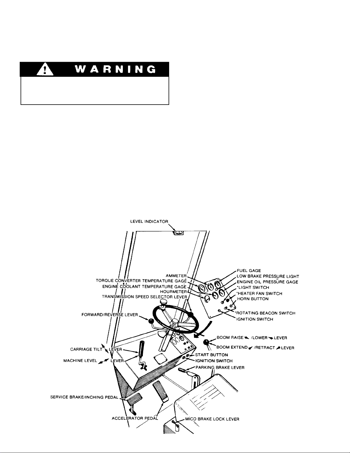
CONTROL AND INSTRUMENT IDENTIFICATION
* Items preceded by an asterisk are optional and may not be furnished on your handler.
CHECKS AND SERVICES
BEFORE STARTING ENGINE
(T o be performed at beginning of each work shift)
enter these ports, it can shorten the life of o-rings.
seals, packings and bearings.
Use extreme caution when checking items
beyond your normal reach. Use an
approved safety ladder.
Before removing filler caps or fill plugs, wipe all dirt
and grease away from the ports. If dirt is allowed to
Complete all required maintenance before operating unit.
When adding fluids or changing filter elements,
refer to the lubrication section of this manual to
determine the proper type to be used.
If spark arrestors are required, be sure they are in
place and in good working order.
Service the unit in accordance with the lubrication
and maintenance schedule.
Inspect unit for obvious damage, vandalism
and needed maintenance. Check for signs of fuel,
lubricant, coolant and hydraulic leaks. Open all
access doors and look for loose fittings, clamps,
components and attaching hardware. Replace
hydraulic lines that are cracked, brittle, cut or show
signs of abrasion.
Inspect all structural members, including attachment, for signs of damage.
Check to be sure rear planetary hubs are properly
set for the type of travel expected.
6
ENGINE OPERATION
NOTE: If engine is being started at beginning of work shift be sure to perform all “ CHECKS AND
SERVICES BEFORE STARTING ENGINE” (Page 6).
Starting Engine
Check to be sure that all controls are in neutral
1.
and that all electrical components (lights, heater,
defroster, etc.) are turned off. Set parking brake.
Insert ignition key and turn clockwise to ON
2.
position. Low brake pressure light should glow
and continue to glow until brake system
accumulator is fully charged.
Depress accelerator pedal approximately 1/4 to
3.
1/3 of travel from top.
Turning ignition switch to START position
while engine flywheel is rotating can cause
serious damage to engine and/or starting
motor.
NOTE: If temperature requires the use of a starting
aid, and if your handler is equipped with a factory-
installed ether starting aid, fully raise and depress
starting aid knob one time only before cranking
engine. If you use a different starting aid, be sure to
follow manufacturer’s instructions carefully.
Excessive ether may damage engine.
Turn ignition key clockwise to on position and
4.
depress start button to engage starting motor.
Release button immediately when engine starts.
If engine fails to start within 20 seconds, release
button and allow starting motor to cool for a few
minutes before trying again.
After engine starts, observe oil pressure gage. If
5.
gage remains on zero for more than ten seconds,
stop engine and determine cause. Correct cause
of malfunctioning before restarting engine.
Normal engine oil pressure should be in range of
35 - 50 psi (241 - 345 kPa).
Warm up engine at approximately 1/2 throttle
6.
until engine coolant temperature reaches
operating range of 180 - 200°F. (82 - 93°C.).
Cold Weather Starting Aids
Diesel engine ignition is accomplished by heat
generated when fuel/air mixture is compressed
within the cylinders. Because this heat may be
insufficient to start a cold engine in cold weather,
the use of starting aids has become common practice.
Because of the wide variety of starting aids available
it would be impractical to attempt to provide
Normal Engine Operation
Observe gages frequently to be sure all engine
systems are functioning properly.
The ammeter shows the charge/discharge rate of the
battery charging system. With the engine running, a
discharge reading (-) or a continuing high charge
reading (+) indicates a problem in the battery
charging system.
Be alert for unusual noises or vibration. When
an unusual condition is noticed, stop machine in a
safe position and shut off engine. Determine cause
and correct problem before continuing.
specific instructions for their use in this manual.
Carefully follow instructions furnished with your
starting aid.
If you use a starting aid employing ether or a
similar substance pay particular attention to
manufacturer’s warnings.
Avoid prolonged idling. Idling causes engine
temperature to drop and this permits formation of
heavy carbon deposits and dilution of lubricating oil
by incompletely burned fuel. If the engine is not
being used, turn it off.
Always keep engine covers closed while
engine is running.
continued...
7

Stopping the Engine
Operate engine at idle speed for a few minutes
before turning it off. This allows engine coolant
and lubricating oil to carry excessive heat away
from critical engine areas.
Do not “gun” engine before shut down; this
practice causes raw fuel to remove oil film from
.
WARM UP & OPERATIONAL CHECKS
cylinder walls and dilute lubricant in crankcase.
To stop engine, allow engine to run at idle for a few
minutes and then turn key counterclockwise to stop
position. Be sure to remove key from ignition switch
before leaving cab.
(T o be performed at beginning of each work shift)
Complete all required maintenance before operating unit
The safety, efficiency and service life of your unit
will be increased by performing the operational
checks listed below. Items preceded by an asterisk
(*) are optional and may not be furnished on your
machine. Check items during warm-up period.
6.
7.
Forward and reverse travel in all gears
“Inching” travel - should be smooth through
full pedal travel
*1.
*2.
3.
4.
When engine warms to operating range, check
the following items:
5.
Heater, defroster and windshield wiper
Operating lights and rotating beacon
Low brake pressure light - should go out with
engine running above idle
Ammeter - should show low charging rate after
charging system has replaced starting drain
Service brake, parking brake and Mico brake
lock.
Continued operation with hydraulics fluid
by-passing the filter (yellow flag
showing) can cause severe damage to
hydraulic system components.
8.
Horn and back-up alarm
9.
All boom and attachment functions - full stroke
10
Hydraulic Filter Condition Indicator - observe
torque converter temperature gage after starting normal operation. When needle has been in
operating range for an hour or so, stop handler
in a safe area and set parking brake. With
engine running, check hydraulic filter
condition indicator. When yellow flag fills
indicator window, filter is clogged and
hydraulic oil is bypassing filter. Filter must be
changed before reaching bypass condition
(change before yellow flag reaches midpoint of
window).
8
BRAKE SYSTEM
General
The brake system furnished on The handler includes
a service brake, parking brake and Mico lock.
Because service braking and “inching” (slow travel)
functions overlap, some features of inching will be
discussed here. Refer to Drive Train Section for
additional information on inching travel.
Inching Travel
Overlap between service braking and inching occurs
because the same foot pedal controls both
functions and also because both functions control
travel speed. However, the methods of controlling
travel speed are quite different: service braking
involves a controlled stopping force applied to the
front wheels while inching involves a controlled
driving force applied to the rear wheels.
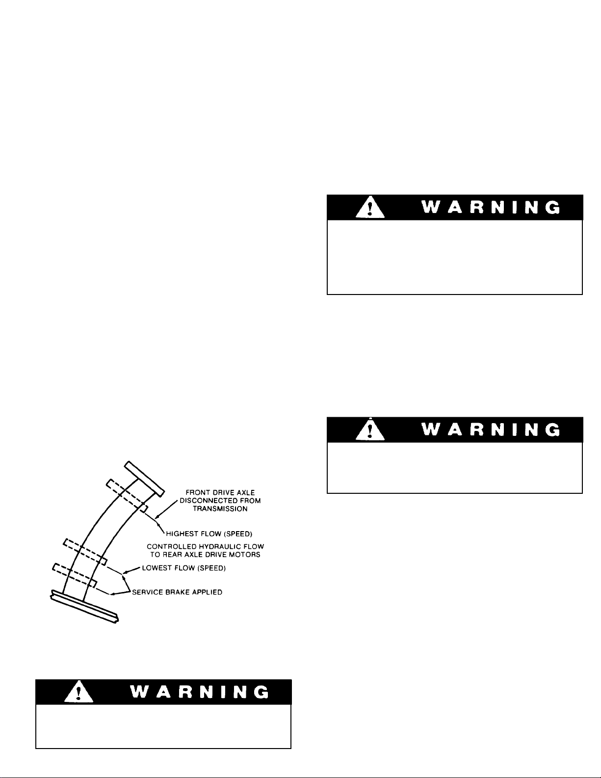
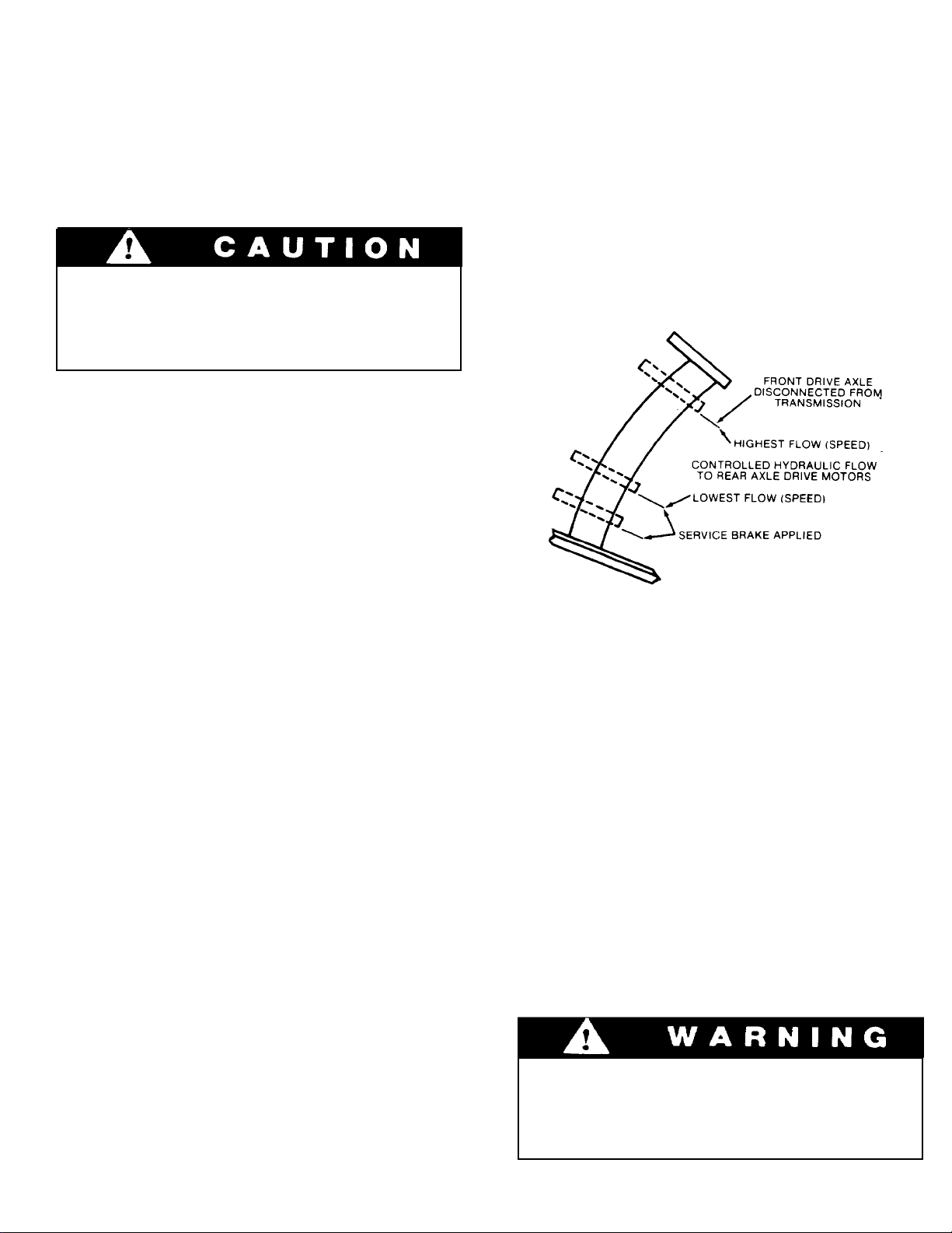
The service brake/inching pedal has three separate
functions:
1.
It disconnects front drive axle from
transmission.
2.
It controls hydraulic flow to rear axle drive
motors (hydraulic flow regulates speed).
Service Brakes
The power-assisted hydraulic service brake is
applied only to front wheels of handler.
When the service brake/inching pedal is depressed
far enough to actuate the service brake master
cylinder, brake fluid flows to wheel cylinders to
apply service brake. At the same time, pilot pressure
is applied to a piston within master cylinder to
intensify (boost) pressure to wheel cylinders.
Though it is possible to stop the handler
without the power assist feature, very
heavy foot pressure is required and
stopping distance will be significantly
greater.
Mico Lock
The Mico Lock can be used to reduce operator
fatigue by temporarily locking a service brake
application on using a hand lever rather than holding
brake pedal.
3.
It applies service brake.
As illustrated, the three functions occur in sequence
as service brake/inching pedal is depressed from top
to bottom of stroke.
Practice inching/braking in a safe, open
area until you are thoroughly familiar with
response of machine to pedal travel.
Never use Mico Lock as a parking brake.
The brake application will bleed off after a
short time and allow the machine to roll.
T o Apply Mico Lock
Check to be sure Mico Lock lever is pushed
1.
forward to release position (lever horizontal).
Depress service brake pedal fully and hold.
2.
Pull Mico Lock lever back to lock position (lever
3.
vertical) and then release brake pedal.
To Release Mico Lock
Release Mico Lock by pushing lever forward to
release position (lever horizontal).
9
contined...
Parking Brakes
The parking brake locks the front axle by means of a
cable actuated brake caliper acting on a brake disc
attached to the axle input yoke.
Parking brake tension can be increased by turning
knob at end of lever clockwise.
To apply the parking brake, pull parking brake
lever to rear (toward vertical position).
STEERING SYSTEM
To release parking brake, push parking brake
lever forward (to horizontal position).
Always apply parking brake before leaving
cab. Neither leaving the unit in gear nor
applying the Mico Lock will prevent unit
from rolling. Refer to page 17 for parking
procedure.
Ninety degree rear wheel power steering is provided
to reduce operator fatigue and to permit high
maneuverability in close quarters.
Be alert for any increase in effort needed to
steer. It any difference is noted, notify
maintenance personnel immediately for
correction. It power assist feature should
fail for any reason IT WOULD BECOME
VERY DIFFICULT TO STEER. For this
reason it is extremely important that you
NEVER TURN ENGINE OFF WHILE
TRAVELING.
In the event power steering fails, stop as
soon as possible. Do not drive unit until
problem has been corrected.
It is important that the operator practice
maneuvering the handler in a safe, open area until
he becomes thoroughly familiar with steering
response and clearance required for tailswing and
load when turning.
10
DRIVE TRAIN
General
The drive train provides two and four wheel drive
and includes the engine, torque converter,
transmission, propel shaft and front and rear
driving axles.
Inching travel is directly related to drive train
functions and will be discussed in this section.
Two & Four Wheel Drive
The drive train is designed to provide two wheel
drive (front axle driving) or tour wheel drive (both
front and rear axles driving).
Under certain conditions, changing from four wheel
drive to two wheel drive may cause a difference in
the way the machine responds to steering, braking
and drive controls. Always be aware of which travel
mode you are using.
There are two ways to disengage rear wheel
drive:
Shift to third gear (rear axle drive is engaged only
1.
in first and second gears)
2.
Disengage rear planetary hubs (refer to Rear
Drive Axle heading in this section)
Transmission
The transmission provides three speed ranges for
both forward and reverse travel.
Gear 1st 2nd 3rd 3rd*
mph 2.8 6.0 15.9 17.9
kmph 4.5 9.6 25.6 28.8
*With rear planetary hubs disengaged
There are three operator controls for the
transmission:
Gear Selector Lever (for 1st, 2nd and 3rd gears)
1.
Direction Selector Lever (for forward, neutral
2.
and reverse)
Service Brake/Inching Pedal (refer to Inching
3.
Travel heading in this section)
To Operate Transmission:
Release parking brake and hold handler in
1.
position using service brake.
Move gear selector to appropriate speed range
2.
(1st, 2nd or 3rd gear). The gear selector may be
shifted while traveling. When traveling downhill,
use the same gear needed to travel up the hill.
NOTE: Rear drive axle can also be disengaged in
response to overload in associated electrical
circuitry causing automatic reset type circuit
breaker to trip (open). Breaker will close again in
approximately ten seconds.
Torque Converter
There are no operator controls for the torque
converter. It functions automatically to permit
starting from a standstill in any transmission speed
range.
An oil temperature gage is provided to indicate
operating temperature of torque converter/transmission. Normal operating temperature is 180 200°F. (82 - 93°C.). If overheating occurs, attempt
to lower temperature by traveling in a lower gear. If
necessary, stop and allow torque converter to cool
with engine running and gear selector in neutral. Be
sure radiator fins are clean.
Continued operation of overheated torque
converter/transmission can cause serious
damage to these components.
Never shift gear selector or direction
selector to cause a sudden change of
travel speed or direction. Such a change
could cause load to shift or machine to tip
over. Reversing direction while traveling
can also damage transmission.
Move direction selector to forward or reverse
3.
position as required.
Release service brake and depress accelerator to
4.
attain appropriate speed.
Stop handler by releasing accelerator and
5.
applying service brake.
Move direction selector to neutral position.
6.
Apply Mico Lock or parking brake as
7.
appropriate.
Front Driving Axle
The front driving axle includes a differential and
planetary drive hubs and is powered by a propeller
shaft from the transmission. The service
brake/inching pedal is the only operator control for
the front axle (refer to Inching travel Heading).
11
contined...
Rear Driving Axle
The rear driving axle includes planetary hubs which
are powered by hydraulic motors mounted on the
inner face of the hubs. Hydraulic flow to drive
motors is provided only in first and second gear
speed ranges. Drive motors are free-floating in third
gear.
Continuous driving for two miles or more
in third gear, with rear driving hubs
engaged, can damage hydraulic drive
motors.
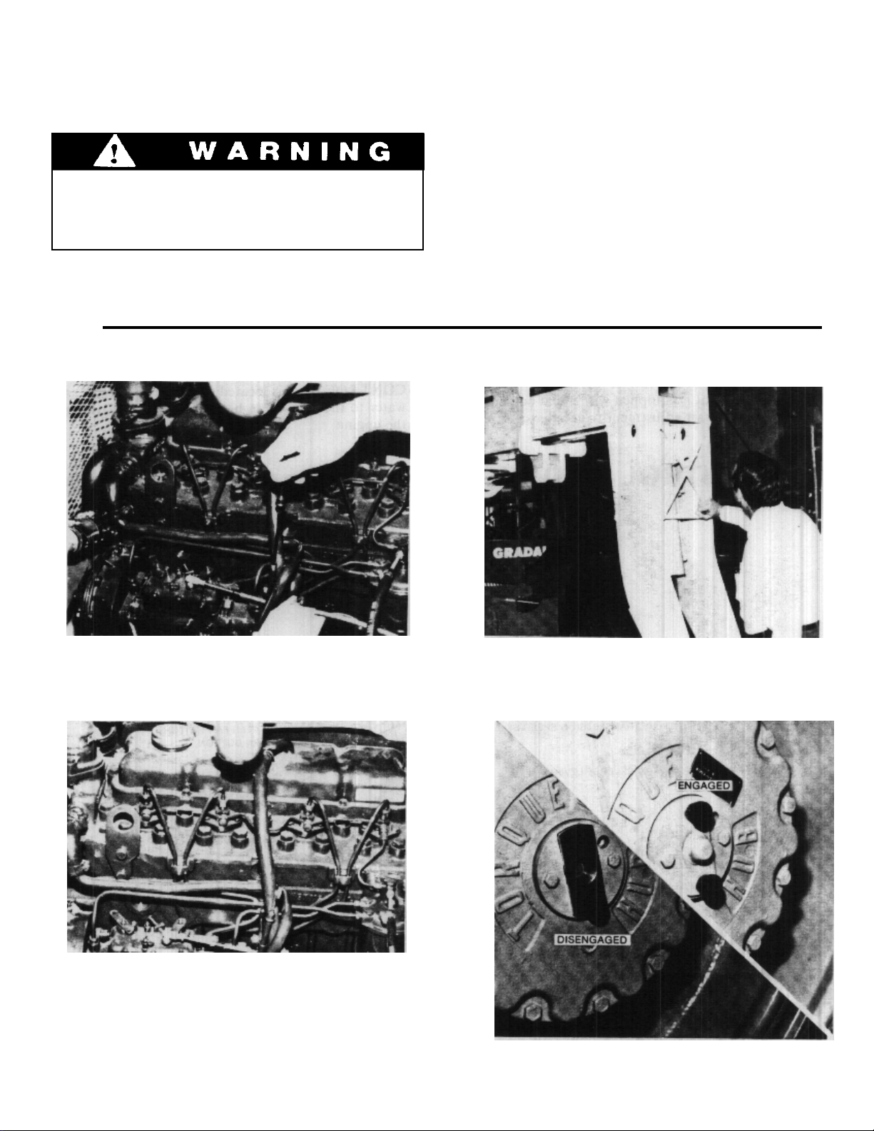
To Disengage Rear Driving Hubs:
Apply parking brake and remove key from
1.
ignition switch.
Remove thumb scre
2.
Remove and rotate plate per photo on pg. 6 (cup
3.
out - engaged - cup in - disengaged).
ws from keeper pin plate.
travel functions only in first and second gears. There
is no hydraulic flow to drive motors in third gear.
Inching travel is controlled by the service
brake/inching travel pedal. This pedal has three
separate functions:
It disconnects front drive axle from
1.
transmission.
It controls hydraulic flow to rear axle drive
2.
motors (hydraulic flow equals speed).
It applies service brake.
3.
4.
Secure plate using thumb screws.
5.
Repeat procedure for other hub.
To Engage Rear Driving Hubs: Repeat procedure.
NOTE: If machine is moved with keeper pin plate
removed, input shaft pin will pop out.
Hydraulic flow to rear axle drive motors is
controlled electrically. An automatic reset type
breaker is included to prevent damage from
overload. If circuit breaker trips (opens) rear
axle drive will be inoperative for approximately
ten seconds until breaker resets. Notify
maintenance personnel if circuit breaker trips
repeatedly.
To determine whether circuit breaker has tripped,
attempt to move machine using inching travel. If
machine does not respond to inching travel pedal
circuit breaker is open.
As illustrated, the three functions occur in sequence
as pedal is depressed from top to bottom of stroke.
To Engage Inching Travel:
Depress service brake/inching travel pedal
1.
approximately 1-1/2 inches to disengage front
driving axle from transmission. At this point rear
drive motors are receiving full flow and travel
speed will not have changed.
Continue to depress pedal to reduce speed - the
2.
more pedal travel, the less speed.
T o stop, depress pedal fully .
3.
OR
To resume normal travel release service brake/
inching travel pedal. Depress accelerator pedal to
attain appropriate speed.
Inching Travel
Inching travel is provided to permit very slow travel
while maintaining high engine speed for other
functions. Because inching travel depends on
hydraulic flow to rear axle drive motors, inching
Practice inching/braking in a safe, open
area until you are thoroughly familiar with
response of machine to pedal travel
12

Leveling
MATERIAL HANDLING
The handler is designed to permit tilting main frame
eight degrees to left or right to compensate for
uneven ground conditions.
Raising the boom (loaded or unloaded)
when handler is leaning to the side can
cause machine to tip over with little or no
warning.
A level indicator is located on upper portion of front
window frame to permit operator to determine that
machine is or is not level.
The rear axle pivots at the midpoint of the main
frame to help assure that wheels will remain in
contact with ground. A hydraulic cylinder provides
a rigid connection between front axle and main
frame to help assure a solid work platform and
permit tilting main frame to left or right.
NOTE: The frame leveling function is provided only
to level the machine before lifting or placing a load.
Do not attempt to use leveling feature to turn on or
travel across a slope.
To Level Handler:
Position machine in best location to lift or place
1.
load and apply brake.
Observe level indicator to determine whether
2.
machine must be leveled. Note position of
indicator for later realignment.
If necessary, position boom in carry position and
3.
move carriage tilt/machine level lever to left or
right to level machine. Move lever to left to lower
left side of frame or move lever to right to lower
right side frame.
Lift or place load as appropriate.
4.
Retract and lower boom to carry position.
5.
Realign frame to position noted in step 2.
6.
If handler cannot be leveled using leveling
system, do not attempt to raise or place
load. Have surface leveled.
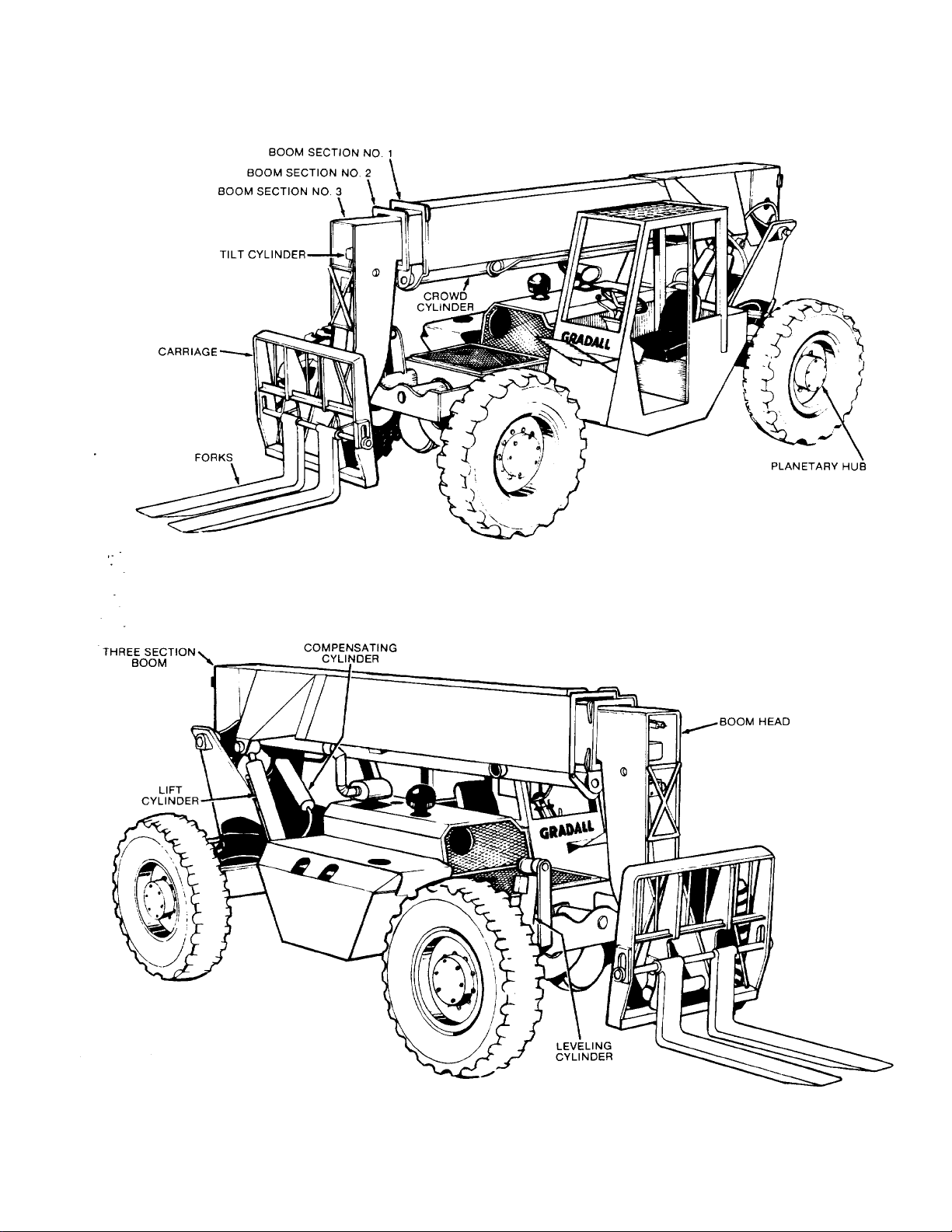
Boom
The three section hydraulically operated boom
provides maximum reach of 36 feet above
horizontal at 70° elevation and 21 feet forward of
forward edge of front tires at 0° elevation (measured
to heel of standard forks mounted on standard
carriage). Boom travel extends from 4° below
horizontal to 70° above horizontal.
Raise boom by pulling boom lever to rear and lower
boom by pushing boom lever forward.
Boom extension and retraction is accomplished by a
hydraulic crowd cylinder anchored at rear of boom
section no. 1 and at front of boom section no. 2 and
also by a cable and push beam arrangement within
the boom sections. Extension or retraction of
boom section no. 2 is always equaled by a
corresponding movement of boom section no.
3.
A hydraulic cylinder is located within the boom
head to tilt the fork carriage or other attachment
back and forth as required.
The tilt cylinder is controlled by carriage tilt/
machine level lever. Push lever forward to tilt
attachment down or pull lever to rear to tilt
attachment up.
Extend boom by moving boom lever to right and
retract boom by moving boom lever to left.
A compensating cylinder is pinned to main frame
and to base of boom section no. 1. As boom is
raised, oil is transferred from rod end of
compensating cylinder to rod end of attachment tilt
cylinder. Lowering boom causes transfer of oil from
barrel end of compensating cylinder to barrel end of
attachment tilt cylinder. This transfer of oil causes
extension and retraction of tilt cylinder to maintain
angle of attachment as boom is raised and lowered.
All cylinders related to boom (attachment tilt, raise/
lower and extend/retract) are protected by pilot
operated check valves which prevent load from
falling in event of a broken hydraulic hose or tube.
13
Attachments
Although the carriage/fork combination is most
frequently used, a number of other attachments are
available for use with the handler.
can be provided for light duty work. A truss boom is
available to extend maximum reach and height and
can be fitted with a winch when required. Consult
your Gradall/Loed Materials Handler Dealer for
information on attachments designed to solve
special material handling problems.
Attachment Capacities
The Rated Capacity Chart, located on left side of
dashboard, indicates maximum capacities for
handlers equipped with standard carriage/fork
combination. These capacities apply only to
standard carriage fork combination and cannot be
used for other attachments.
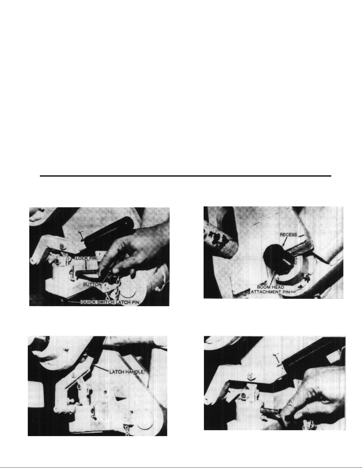
Attachment Installation
A serial number plate is attached to all attachments
and indicates maximum capacity for that
attachment. However, the capacity shown on
this plate may be incorrect in relation to your
machine.
Refer to Attachment Capacity Plate, located below
Serial Number Plate on right cab wall, for correct
maximum capacity for all attachments furnished
with your machine. If attachment in question is not
listed on this plate, contact factory for maximum
capacity.
Refer to Operating Procedures and Techniques
section for instructions on proper use of
information shown on capacity plates.
1. Depress button and remove lock pin from quick
switch latch pin.
2. Raise handle to retract latch pin fully .
3. Position boom head attachment pin fully in recess
of attachment. Tilt upward slightly to assure full
engagement.
4. Depress handle fully to engage latch pin in
attachment and install lock pin in latch.
14
OPERATING PROCEDURES & TECHNIQUES
This section highlights some common procedures
and discusses areas which may be new to even the
experienced operator.
Hydraulic Controls
All boom and attachment movements are governed
by hydraulic controls. Rapid, jerky operation of
hydraulic controls will cause rapid, jerky movement
of the load. Such movements can cause the load to
shift or fall or may cause the machine to tip over.
Feathering
Feather is a technique of control operation used for
smooth load handling. To feather controls. move
control lever very slowly until load begins to move,
then gradually move lever further until load is
moving at desired speed. Gradually move lever
toward neutral as load approaches destination.
Continue to reduce load speed to bring load to a
smooth stop. Feathering effect can be increased by
lowering engine speed at beginning and near end of
load movement.
With boom raised above horizontal, forks can be
removed from a load by moving boom control lever
back and to the left until forks move rearward
horizontally.
With boom lowered below horizontal, forks can be
inserted under a load by moving boom control lever
back and to the right until forks move forward
horizontally.
With boom lowered below horizontal forks can be
removed from a load by moving boom control lever
forward and to the left until forks move rearward
horizontally.
The closer the boom to horizontal, the less boom
raise/lower movement required for inserting and
removing forks.
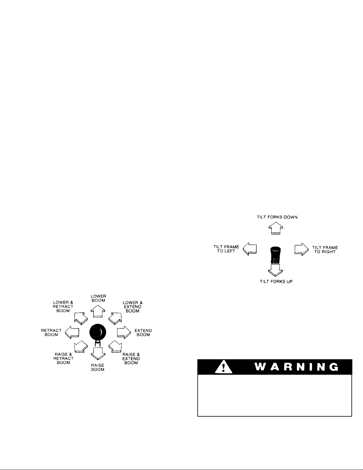
Carriage Tilt/Machine Level Lever
Boom Control Lever
The boom control lever can be positioned to cause
individual boom movements or combinations of
boom movements as illustrated.
With boom raised above horizontal, forks can be
inserted under a load by moving boom control lever
forward and to the right until forks move forward
horizontally.
Move lever forward to tilt forks down and move
lever to rear to tilt forks up.
Move lever to left to tilt main frame to left and move
lever to right to tilt frame to right.
Always move boom to carry position
(horizontal or below) before leveling
frame. Attempting to level machine with
boom raised may cause it to tip oven.
15
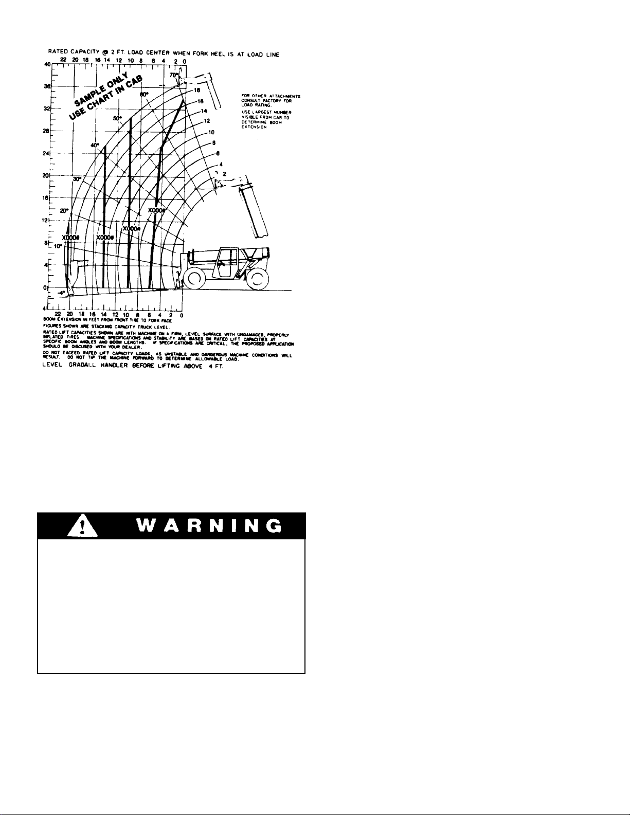
Rated Capacity Chart
Boom Extension
Numbers across bottom of chart (0' to 22') and
numbers parallel to boom (2' to 18') represent boom
extension as measured from fully retracted position
to extended position. These numbers do not reflect
total boom length, only the number of feet of
extension from fully retracted position.
Number decals on boom section number two (4, 8
12, 16 and 20) relate directly to boom extension. The
largest number which can be read from operator’s
seat indicates total boom extension.
Boom extension relates to dimension “D” shown on
serial number plate.
Boom Angle
Numbers at ends of angled fines (4° to 70°)
represent angle of boom to horizontal as measured
from horizontal plane at ground level. Maximum
angles are 4° below horizontal with boom fully
lowered to 70° above horizontal with boom fully
raised.
General
The rated capacity chart, located on left side of
dashboard, indicates maximum load capacities for
handlers equipped with standard carriage/fork
combination. These capacities apply only to the
standard carriage/fork combination and cannot be
used for other attachments.
All loads shown on rated capacity chart
are based on machine being on firm, level
ground; the forks being positioned evenly
on carriage; the load being centered on
forks; proper size tires being properly
inflated; and the handler being In good
operating condition. Machines having
8000 pound capacity must have tires
properly filled with calcium chloride.
A boom angle indicator is located on left side of
boom section number one to show boom angle. Be
sure machine is level from front to rear or indicator
will provide incorrect reading.
Load Center
Loads shown on rated capacity chart are based on
the load center being two feet above and two feet
forward of surfaces of horizontal forks as indicated
by dimensions “B” and “C” on serial number plate.
The load center of a load is the center of gravity of
the load. For regularly shaped loads of the same
material, such as a pallet of blocks, the center of
gravity can be located by measuring the load to find
its center. For irregular loads, or loads of dissimilar
materials, keep the heaviest part of the load as close
to the heel of the forks as possible.
In all cases, the load center must be centered
between the forks.
Load Limits
Elevation:
Numbers at left side of chart (-4' to 40') represent
elevation at heel of horizontal fork as measured
from level ground. Maximum elevation with boom
fully raised and extended is 36 feet. Elevation relates
to dimension “A” shown on serial number plate
located on right cab wall.
Some capacities shown on the rated capacity chart
are based on machine stability and some are based
on hydraulic lift capacity. The “common sense” or
“feel” an experienced operator might apply in
regard to “tipping loads” DOES NOT APPLY to
hydraulic load limits. Exceeding load limits can
cause a relief valve to open allowing the load to fall,
or in some cases, the machine to tip over.
16

based on hydraulic limitations, the maximum load
may be handled anywhere within reach of machine.
Never use “tipping” method to determine
safe lifting capacity. This could cause the
load to fall or the machine to tip over.
Material Handling Bucket Capacity
Lift capacity for a material handling bucket, if
furnished with the handler, is shown on the
Attachment Capacity plate located on right cab wall
below Serial Number plate. If part number on
bucket does not match part number on Attachment
Capacity plate, contact factory for proper bucket
lift capacity .
The bucket lift capacity is based on machine being
on firm, level ground; proper size tires being
properly inflated; and the handler being in good
operating condition.
Because maximum bucket rated lift capacity is
Truss Boom/W inch Capacity
Lift capacity for a truss boom or a truss
boom/winch combination. If furnished with the
handler, is shown on the Attachment Capacity
plate. If the part number shown on the boom does
not match the part number shown on Attachment
Capacity plate, contact factory for proper boom lift
capacity.
The truss boom lift capacity is based on machine
being on firm level ground; proper size tires being
properly inflated; the handler being in good
operating condition; and the load being suspended
vertically form the boom.
Side loads or swinging loads can cause structural
damage and may cause the machine to tip over.
Because maximum truss boom lift capacity is based
on hydraulic limitations, the maximum rated load
may be handled anywhere within reach of the
machine.
1. Position unit in a safe, level parking area.
Parking brake may not hold machine on a
grade.
2. Apply parking brake and chock wheels.
3. Retract and lower boom fully.
1.
Clean and inspect machine thoroughly and perform all required maintenance.
2.
Coat all cylinder rods with a good grade of
grease or rust preventative.
PARKING
4.
Turn off all electrical accessories.
5.
Allow engine to cool at idle speed for a few
minutes and then turn off. Remove ignition
6.
key.
7.
Fill fuel tank to minimize condensation.
8.
Disconnect battery if unit is in an area where
tampering seems possible.
Lock cab (if so equipped).
STORAGE
3.
Park machine in a dry enclosure and remove
batteries.
4.
Prepare engine in accordance with engine
manufacturer’s instructions.
17
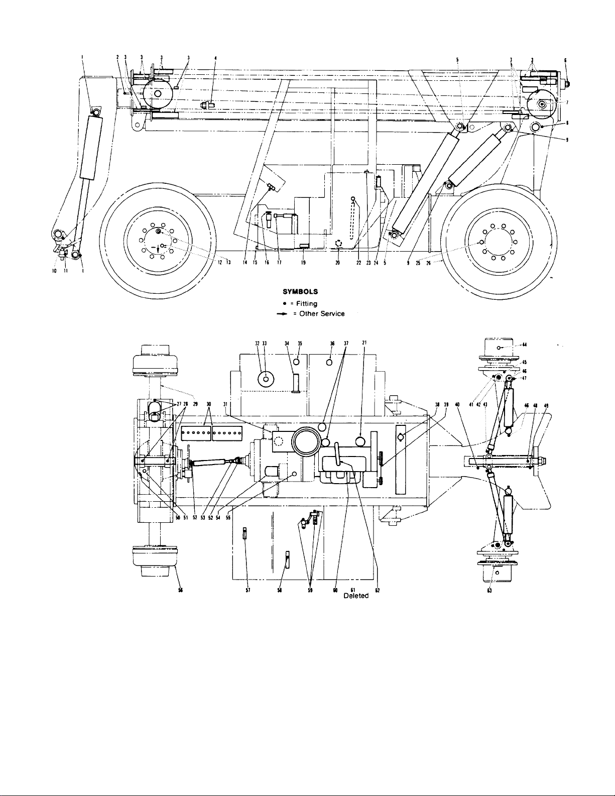
LUBRICATION & MAINTENANCE DIAGRAM
Lubricate points indicated by dotted leaders
•
on both sides of unit.
Intervals shown are for normal (8 hour day)
•
usage and conditions. Adjust intervals for
abnormal usage and conditions.
•
See recommended lubricants (page 20).
•
Apply a light coating of engine oil to all linkage
pivot points.
Lubricate Notes
•
•
•
•
18
Clean lubrication fittings before lubricating.
Clean filter and air cleaner housing using
diesel fuel. Dry components thoroughly using
a lint free cloth.
Check lubricant levels when lubricant is cool.
Drain engine and gear cases only after
operation when lubricant is hot.

Daily or Every 10 Hours
Carriage Tilt Cylinder Pivots
1.
Boom Extension Cable Sheave
2.
Boom Slide Bearings (extend boom fully and coat all
3.
wear paths on boom sections 2 and 3 - retract and extend
boom fully three times and wipe excess grease from
bearings)
Boom Hoist Cylinder Pivots
5.
Boom Retraction Cable Sheave
7.
Boom Pivot
8.
Compensating Cylinder Pivots
9.
Boom Head/Carriage Pivot
10.
Carriage Tilt/Machine Level Lever Pivot
14.
Transmission Dipstick (check level & replenish as
16.
req’d)
Engine Dipstick (check level & replenish as
22.
req’d - item 23 is filler port)
Tires (inspect for damage)
26.
Leveling Cylinder Pivots
27.
Front Axle Pivot
28.
Hydraulic Filter Condition Indicator (check with oil
33.
at operating temperature - replace filter as req’d)
Hydraulic Reservoir (check level & replenish as
35.
req’d)
Fuel Tank (fill daily after shut down)
36.
Radiator (check level and replenish as req’d
38.
using proper coolant)
Rear Axle Pivot (front bearing)
40
King Pins (upper)
41
King Pins (lower)
42
Tie Rods (inner pivot)
43
Planetary Hub
45
Steering Cylinder Pivots
46
Tie Rod Pivots (outer)
47
Idler Arm Pivot
48
Rear Axle Pivot (rear bearing)
49
Service Brake Adjustment (check for
56
minimum of 1" space between fully depressed
brake pedal and floor)
Accelerator Pedal Pivot (under cab)
57
Brake/Inching Travel Pedal Pivot (under cab)
58
Boom Lever Linkage (under cab)
59
Deleted
61
Weekly or Every 50 Hours
Boom Retraction Cable (inspect cable and replace
*4
if damaged - extend boom about 15 feet and
check tension - should be torqued to 75 ft/lbs)
Boom Extension Cable (inspect cable and replace if
*6
damaged - extend boom fully and then retract a few
feet and check tension - should be torqued to 75 ft/lbs)
Quick Switch Latch
11
Front Planetary Hub Level Plugs (check level with
12
arrow pointing down as shown - replenish as req’d) - 2
Brake Master Cylinder Reservoir (under cover
24
behind cab - check level and replenish as req’d)
Tires (check pressure and adjust as req’d - 55 psi) (on
26
8000 pound unit, thump check tires for 90% fill
of calcium chloride mixture)
Batteries (check electrolyte level & replenish
30
as req’d)
Engine Drive Belts (check condition and tension -
*39
adjust or replace as req’d)
*To be performed by qualified maintenance personnel in
accordance with service manual instructions.
Lube No. of
Symbol Points
CG
CG
CG
CG
CG
CG
CG
CG
CG
ATF
EO
CG
CG
-
HF
DF
CG
CG
CG
CG
CG
CG
CG
CG
CG
CG
CG
CG
-
CG
-
BF
-
-
-
2
1
8
2
1
1
2
2
1
1
1
4
2
2
1
1
1
1
1
2
2
2
2
4
2
1
1
1
1
1
3
1
1
1
2
1
4
2
2
19
At End of First Week
*3
Front Boom Slide Bearings (check retaining bolt
torque
13.
Front Hub Drain Plugs (dram and refill)
15.
Transmission Drain Plug (drain and refill)
32.
Hydraulic Filter (replace)
44.
Rear Hub Fill/Level/Drain Plugs (drain and refill refill with plug at 3 or 9 o’clock position)
50.
Front Axle Differential (drain and refill)
54.
Transmission Filter (replace)
Every 2 Weeks or 100 Hours
*3
Boom Slide Bearings (front lower - check for wear &
shim or replace as req’d - no wear permitted past
bevel - check upper rear bearings when lower front
bearings require service - shims are 1/16" thick)
17
Parking Brake (check for proper adjustment
turn lever knob clockwise to increase tension)
20
Engine Crankcase Dram Plug (drain and refill
to level)
21
Engine Oil Filter (replace)
31
Engine Air Cleaner (clean elements and check to
be sure vacuator (rubber cone on bottom) is clear
and undamaged)
52
Drive Shaft Universal Joints
53
Drive Shaft Spline
62
Engine Crankcase Breather Tube (check to be sure
it’s clear)
Every 5 Weeks or 250 Hours
*25
Wheel Lug Nuts (check torque - should be 300 - 310
lb-ft on front/325 - 335 lb-ft on rear
*29
Front Axle (check mounting bolt torque - should be
545 - 600 lb-ft)
54
Transmission Filter (replace)
Every 3 Months or 500 Hours
15
Transmission Drain Plug (drain and refill to level)
19
Transmission Screen (clean)
32
Hydraulic Filter (replace)
*35
Hydraulic Fluid (have hydraulic oil tested)
36
Fuel Tank (drain sediment)
37
Engine Fuel Filter (replace)
55
Transmission Breather (clean)
*60
Engine Intake & Exhaust Valves (adjust)
Every 6 Months or 1000 Hours
13
Front Planetary Hub Drain Plugs (drain and refill
to level)
31
Engine Air Cleaner (replace element)
44
Rear Planetary Hub Drain Plugs (drain and refill
to level)
50
Front Axle Differential Plug (drain and refill
to level)
51
Front Axle Differential Breather (clean)
Every Year or 2000 Hours
34
Hydraulic Reservoir Suction Screen (clean)
*35
Hydraulic System (drain and refill to level)
36
Fuel T ank Breather/Cap (clean)
38
Engine Cooling System (drain, flush and refill)
*63
Rear Axle Wheel Spindle Snap Rings. (inspect &
replace as req’d.)
Lube No. of
Symbo l Points
-
GO
ATF
-
GO
GO
-
-
EO
-
CG
CG
-
-
-
ATF
-
-
-
-
-
-
-
GO
-
GO
GO
-
HF
-
-
-
12
2
1
1
2
1
1
4
1
1
1
1
2
1
1
40
8
1
1
1
1
1
1
1
1
-
2
1
2
1
1
1
1
1
1
2

Recommended Lubricants & Capacities
Capacities**
Application Symbol When Used Grade Specifications English Liters
Engine Crankcase
EO (engine oil)
All year
10W-30
-
12 quarts
7.8
Engine Cooling System
Transmission
Fuel Tank
Hydraulic System
Differential
Front Planetary Hubs
Rear Planetary Hubs
Boom Bearing Paths
Grease Fitting
Brake master Cylinder
50% water/50% anti-freeze
ATF (automatic trans. fluid)
DF (diesel fuel)
HF (Hydraulic fluid)
GO ( multi-purpose lubricant)
GO ( multi-purpose lubricant)
GO ( multi-purpose lubricant)
CG (ectreme pressure lube)
CG (ectreme pressure lube)
BF (brake fluid)
*Specific hydraulic fluid specifications are shown below.
**Capacities are approximate - check level to be sure.
Hydraulic Fluid Specifications:
All year
All year
All year
All year
All year
All year
All year
All year
All year
All year
Permanent
-
#2
EP 80-90
EP 80-90
EP 80-90
EP2
EP2
-
-
ATF-FM DEXRON
-
A.S.L.E. No. H-215*
A.P .I. GL-5
A.P .I. GL-5
A.P .I. GL-5
H-152
H-152
Type A-SAE J-1730C
24 quarts
20 quarts
40gallons
40 gallons
8 quarts
2.5 quarts
44 ounces
-
-
-
22.7
18.9
151.4
151.4
8.4
1.3
1.5
-
-
-
Grade, ASTM 21 5 Viscosity: Carbon Residue, Rams, wt% 0.4
Grade, AGMA 1 SUS at 100° F 215 Zinc, wt% 0.08
Gravity , °API 31.0 SUS at 210° F 48.0 Rust Test. ASTM D 665 A&B Pass
Color, ASTM 2 .0 Viscosity Index 10 5 Oxidation Test. ASTM D 943.
Flash Point, COC, °F 44 0 Aniline Point, °F 22 2 hours to Neut. No of 2.0 2500
Fire Point, COC, °F 49 0 Foam Test, ASTM Pass Emulstion T est, ASTM D 1401,
Pour Point, °F -30 Neutralization Number 1.4 minutes to pass at 130° F 1 0
Copper Corrosion, 3 hr at 212° F 1B
Tire Specifications
Standard: 13:00 x 24 - 12 ply rating - 55 psi
Optional for front only: 15:50 x 25 - 12 ply rating - 55 psi
Model 534B-8 (8000 pound rating) must have tires filled to 90% of capacity with calcium chloride mixture (49 gallons of
water and 245 pounds of calcium chloride per tire).
20
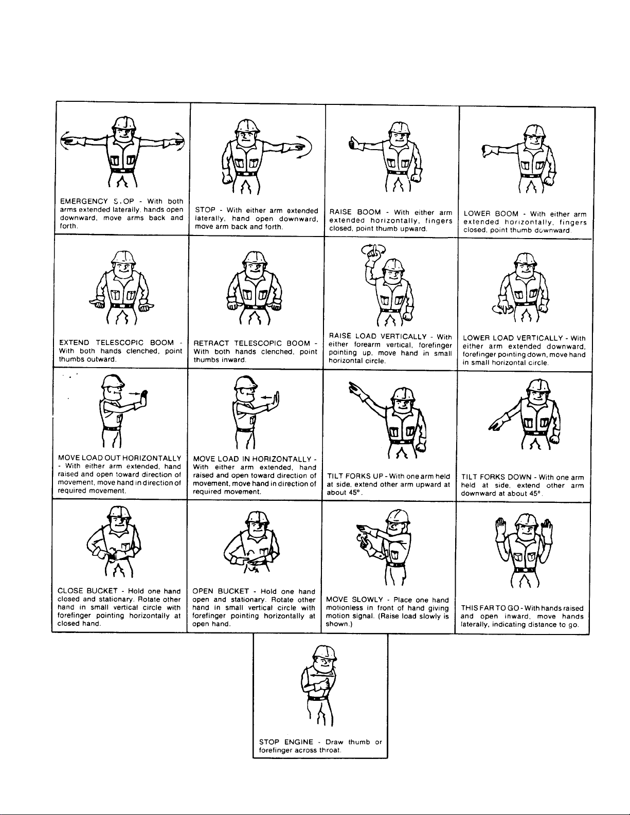
Standard Signals - When handler work conditions
require hand signals, they shall be provided or
posted conspicuously for the use of both signalman
and operator. No handler motions shall be made
unless signals are clearly understood by both
signalman and operator.
Special Signals - When signals for auxiliary
equipment functions or conditions not covered are
required, they shall be agreed upon in advance by
the operator and signalman.
HAND SIGNALS
Instructions - When it is desired to give instructions
to the operator other than provided by the
established signal system, all handler motions shall
first be stopped.

®
®
OPERATION & LUBRICATION MANUAL
®
534
Form #8366
CORPORATE OFFICE
9100-3023
July 2002
Starting S/N
8244001L
Original Issue 12/83
GRADALL DIVISION
JLG INDUSTRIES, INC.
1 JLG DRIVE
McConnellsburg, PA
17233-9533
USA
Telephone: (717) 485-5161
Fax: (717) 485-6417
JLG INDUSTRIES, INC.
406 Mill Avenue S.W.
New Philadelphia, OH
44663
USA
Telephone: (330) 339-2211
Fax: (330) 339-8458

 Loading...