

Gradall 534B Operation Manual

IMPORTANT SAFETY NOTICE
Safe operation depends on reliable equipment and proper operating
procedures. Performing the checks and services described in this manual will
help to keep your Gradall Materials Handler in reliable condition and use of
the recommended operating procedures can help you avoid accidents.
Because some procedures may be new to even the experienced operator we
recommend that this manual be read, understood and followed by all who
operate the unit.
Danger, Warning and Caution notes in this manual and the Gradall Materials
Handler Safety Manual will help you avoid injury and damage to the
equipment. These notes are not intended to cover all eventualities; it would
be impossible to anticipate and evaluate all possible applications and
methods of operation for this equipment.
Any procedure not specifically recommended by The Gradall Company must
be thoroughly evaluated from the standpoint of safety before it is placed in
practice. If you aren’t sure, contact your Gradall Materials Handler
Distributor before operating.
Do not modify this machine without written permission from The Gradall
Company.
NOTICE
The Gradall Company retains all
proprietary rights to the information contained in this manual
The Company also reserves the
right to change specifications without notice
Form No. 8496 12/84
The Gradall Company
406 Mill Avenue, S.W., New Philadelphia, Ohio 44663
INTRODUCTION
General
This manual provides important information to
familiarize you with safe operating procedures and
operator maintenance requirements for the
Gradall Loed 534B Materials Handler.
If you have any questions regarding the materials
handler, contact your Gradall Materials Handler
Distributor.
Operator Qualifications
Operators of the materials handler must be in good
physical and mental condition, have normal reflexes
and reaction time. good vision and depth perception
and normal hearing. He / she* must not be using
medication which could impair his abilities nor be
under the influence of alcohol or any other drug
during the work shift.
The operator should also posses a valid, applicable
driver’s license and must have completed a course of
training in the safe operation of this type of material
handling equipment.
Related Manuals & Decals
Sublications are furnished with the
materials handler to provide information
concerning safety, replacement parts, maintenance
procedures, theory of operation and vendor
components. Replacement manuals, decals and
instruction plates can be ordered from your Gradall
Materials Handler Distributor.
Serial Number Location
Specify Model and Serial Numbers when ordering
parts and when discussing specific applications and
procedures with your distributor. The model/seria
number plate is located on the cab wall to the right
of the operator’s seat pedestal.
In addition, the operator must read, understand and
comply with instructions contained in the following
material furnished with the materials handler:
This Operator’s Manual
Gradall Materials Handler Safety Manual
All instruction decals and plates
Any optional equipment instructions furnished
The operator must also read, understand and
comply with all applicable Employer, Industry and
Governmental rules, standards and regulations.
Regardless of previous experience operating similar
equipment, the operator must be given sufficient
opportunity to practice with the 534B Materials
Handler in a safe, open area (not hazardous to
people or property) to develop the skills and “feel”
required for safe, efficient operation.
*Though no offense or discrimination is intended,
only the masculine pronouns will be used
throughout the remainder of this manual.
Orientation
When used to describe location of components in
the materials handler, the directions front, rear,
right and left relate to the orientation of a person
sitting in the operator’s seat.
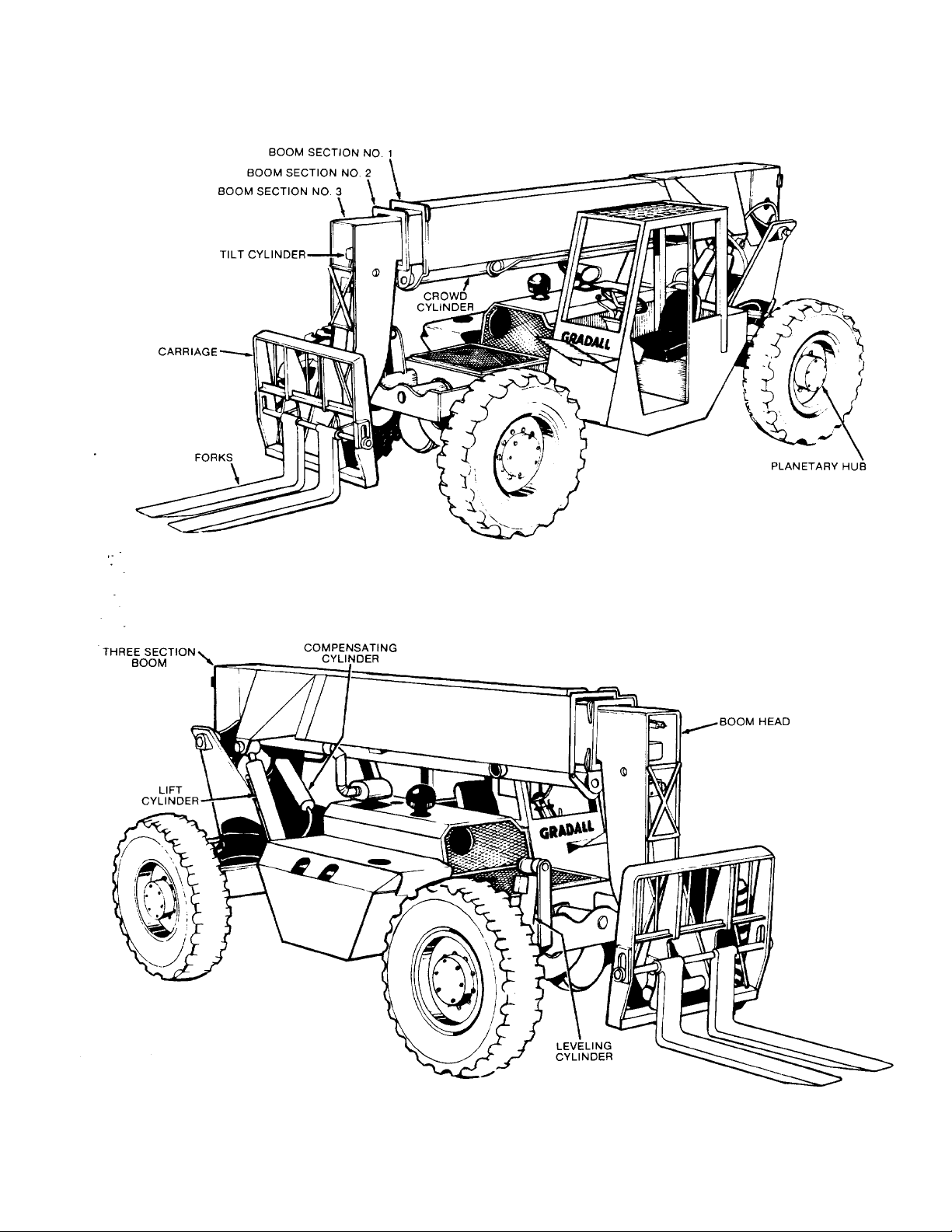
Nomenclature
The illustrations on page 3 include nomenclature
applied to major components of the material
handler. The term “handler” will be used
throughout the balance of this manual in place of
the words “materials handler”.
2
3

SAFETY HIGHLIGHTS
Read and understand this manual, the Gradall
Loed/Materials Handler Safety Manual and all
instructional decals and plates before starting,
operating or performing maintenance procedures
on this equipment.
Most safety notes included in this manual involve
characteristics of the Model 534B Loed/Materials
Handler. Refer to the Gradall/Loed Materials
Handler Safety Manual for safety precautions
relating to general material handling procedures
and practices.
Watch for these symbols; they are used
to call your attention to safety notices.
Operators of this equipment must have successfully,
completed a training program in the safe operation
of this type of material handling equipment.
Regardless of previous experience operating similar
equipment, the operator must be given sufficient
opportunity to practice with the 534B Materials
Handler in a safe open area (not hazardous to
people or property) to develop the skills and “feel”
required for safe, efficient operation.
This symbol indicates an extreme hazard which
would result in high probability of death or
serious Injury if proper precautions are not
taken.
This symbol indicates a hazard which could
result in death or serious injury if proper
precautions are not taken.
This symbol indicates a hazard which could
result in injury or damage to equipment or
property if proper precautions are not taken.
4
OPERA TOR’S CAB
The standard cab is open on three sides and includes
an overhead guard to provide protection from
falling objects.
Never operate the handler unless the
overhead guard is in place and in good
condition.
A fully enclosed cab with Plexiglass windows and a
lockable door is available as an option. The cab
door can be secured in the fully opened or closed
position. Be sure the door is fully secured when
operating the handler.
The operator’s seat is equipped with a seat belt and
includes fore and aft adjustment to compensate for
variations in operator size. The adjustment
release/lock lever is located beneath front edge of
seat. Wear seat belt at all times.
An optional windshield wiper is available for use
with enclosed cabs. An ON/OFF control switch is
located on the wiper motor.
A variable speed defroster fan is available for use
with enclosed cabs. An ON / OFF control switch and
speed control are located on the base of the fan.
A variable speed heater fan is available for use with
units equipped with a heater. An ON/OFF/SPEED
CONTROL knob is located on the dashboard. Hot
water to the heater can be controlled by a valve at
the engine.
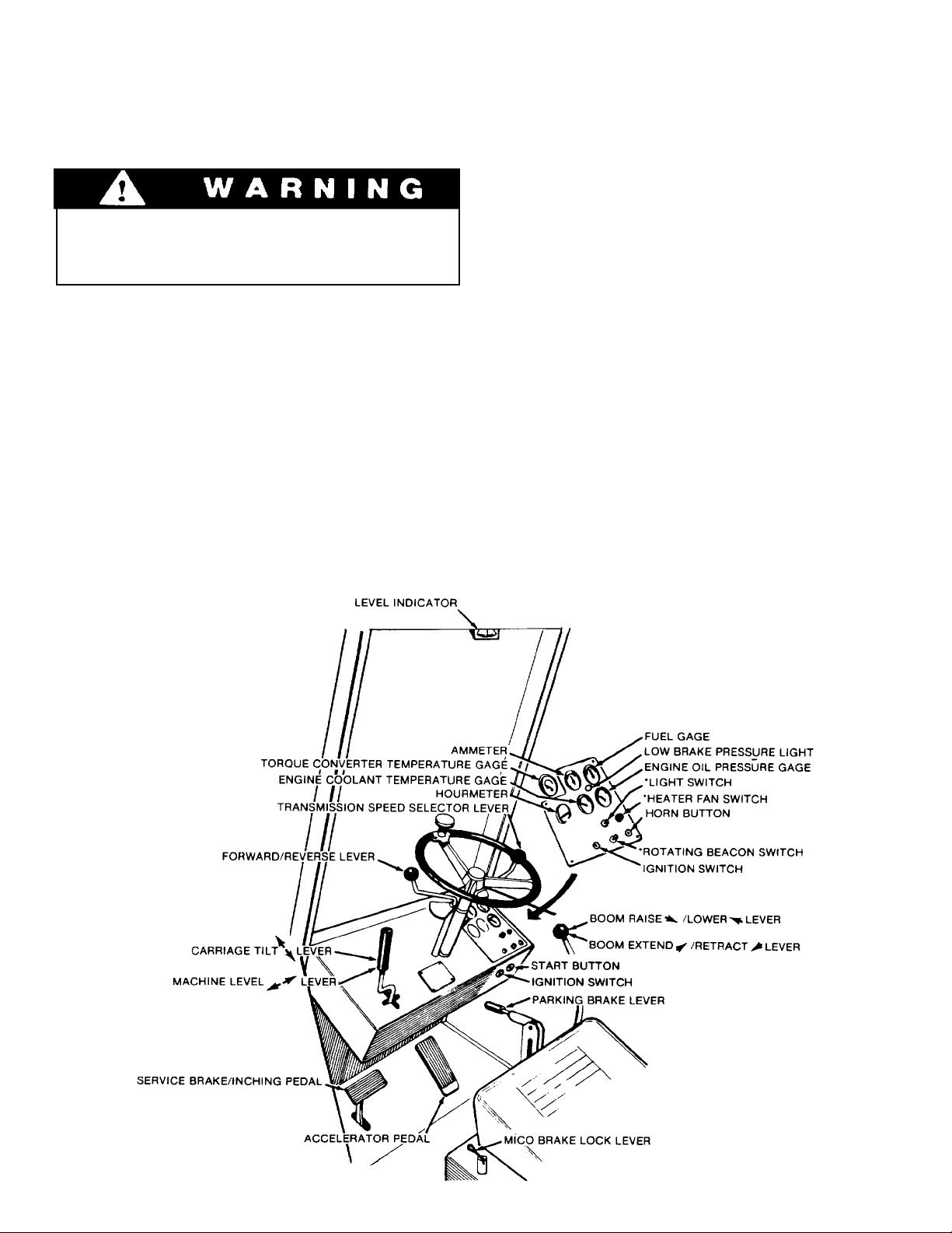
CONTROL AND INSTRUMENT IDENTIFICATION
* Items preceded by an asterisk are optional and may not be furnished on your handler.
CHECKS AND SERVICES BEFORE STARTING ENGINE
(T o be performed at beginning of each work shift)
enter these ports, it can shorten the life of o-rings.
seals, packings and bearings.
Use extreme caution when checking items
beyond your normal reach. Use an
approved safety ladder.
Before removing filler caps or fill plugs, wipe all dirt
and grease away from the ports. If dirt is allowed to
Complete all required maintenance before operating unit.
When adding fluids or changing filter elements,
refer to the lubrication section of this manual to
determine the proper type to be used.
If spark arrestors are required, be sure they are in
place and in good working order.
Service the unit in accordance with the lubrication
and maintenance schedule.
Inspect unit for obvious damage, vandalism
and needed maintenance. Check for signs of fuel,
lubricant, coolant and hydraulic leaks. Open all
access doors and look for loose fittings, clamps,
components and attaching hardware. Replace
hydraulic lines that are cracked, brittle, cut or show
signs of abrasion.
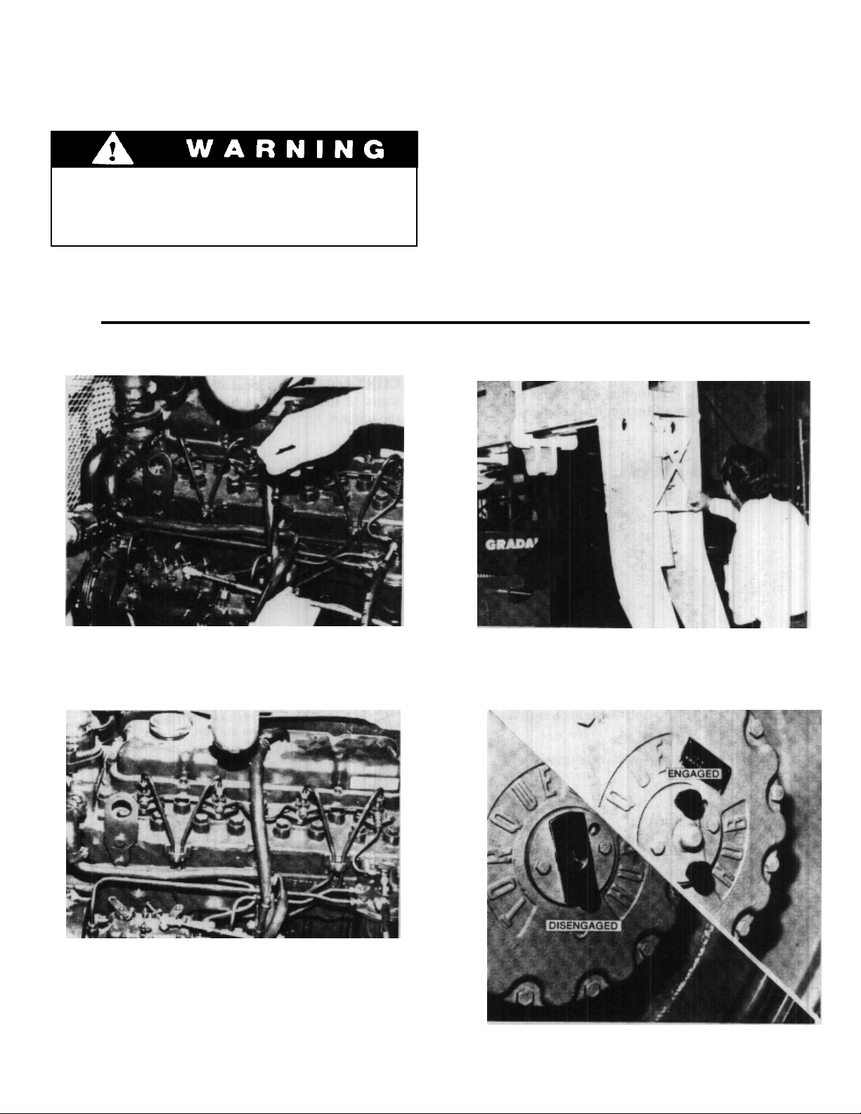
Inspect all structural members, including attachment, for signs of damage.
Check to be sure rear planetary hubs are properly
set for the type of travel expected.
6

ENGINE OPERATION
NOTE: If engine is being started at beginning of work shift be sure to perform all “ CHECKS AND
SERVICES BEFORE STARTING ENGINE” (Page 6).
Starting Engine
Check to be sure that all controls are in neutral
1.
and that all electrical components (lights, heater,
defroster, etc.) are turned off. Set parking brake.
Insert ignition key and turn clockwise to ON
2.
position. Low brake pressure light should glow
and continue to glow until brake system
accumulator is fully charged.
Depress accelerator pedal approximately 1/4 to
3.
1/3 of travel from top.
Turning ignition switch to START position
while engine flywheel is rotating can cause
serious damage to engine and/or starting
motor.
NOTE: If temperature requires the use of a starting
aid, and if your handler is equipped with a factory-
installed ether starting aid, fully raise and depress
starting aid knob one time only before cranking
engine. If you use a different starting aid, be sure to
follow manufacturer’s instructions carefully.
Excessive ether may damage engine.
Turn ignition key clockwise to on position and
4.
depress start button to engage starting motor.
Release button immediately when engine starts.
If engine fails to start within 20 seconds, release
button and allow starting motor to cool for a few
minutes before trying again.
After engine starts, observe oil pressure gage. If
5.
gage remains on zero for more than ten seconds,
stop engine and determine cause. Correct cause
of malfunctioning before restarting engine.
Normal engine oil pressure should be in range of
35 - 50 psi (241 - 345 kPa).
Warm up engine at approximately 1/2 throttle
6.
until engine coolant temperature reaches
operating range of 180 - 200°F. (82 - 93°C.).
Cold Weather Starting Aids
Diesel engine ignition is accomplished by heat
generated when fuel/air mixture is compressed
within the cylinders. Because this heat may be
insufficient to start a cold engine in cold weather,
the use of starting aids has become common practice.
Because of the wide variety of starting aids available
it would be impractical to attempt to provide
Normal Engine Operation
Observe gages frequently to be sure all engine
systems are functioning properly.
The ammeter shows the charge/discharge rate of the
battery charging system. With the engine running, a
discharge reading (-) or a continuing high charge
reading (+) indicates a problem in the battery
charging system.
Be alert for unusual noises or vibration. When
an unusual condition is noticed, stop machine in a
safe position and shut off engine. Determine cause
and correct problem before continuing.
specific instructions for their use in this manual.
Carefully follow instructions furnished with your
starting aid.
If you use a starting aid employing ether or a
similar substance pay particular attention to
manufacturer’s warnings.
Avoid prolonged idling. Idling causes engine
temperature to drop and this permits formation of
heavy carbon deposits and dilution of lubricating oil
by incompletely burned fuel. If the engine is not
being used, turn it off.
Always keep engine covers closed while
engine is running.
continued...
7
 Loading...