

Page 1
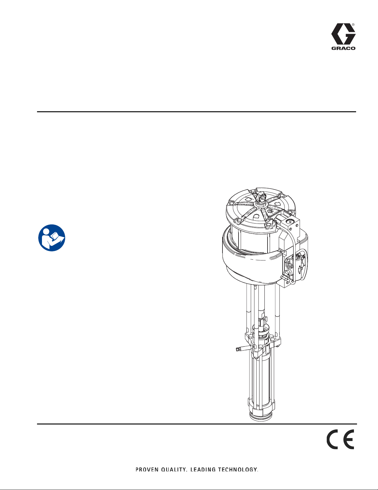
Operation and Parts
™
Dura-Flo
For use with bulk supply of medium to high viscosity sealant and adhesive materials.
For professional use only.
Not approved for use with group 1 fluids as defined by Directive 2014/68/EU (Pressure
Equipment Directive).
Not approved for use in European explosive atmosphere location.
See Technical Specifications page on page 20 for maximum allowable ambient temperature information.
See Page 2 for model information and
maximum working pressure.
Important Safety Instructions
Read all warnings and instructions in this and all
related manuals. Save all instructions.
XL 1000cc Pumps
3A4100E
EN
WLD
Page 2

Contents
Models . . . . . . . . . . . . . . . . . . . . . . . . . . . . . . . . . . . 2
Related Manuals . . . . . . . . . . . . . . . . . . . . . . . . . 2
Warnings . . . . . . . . . . . . . . . . . . . . . . . . . . . . . . . . . 3
Component Identification / Pump Assembly . . . . 5
Motor Component Identification . . . . . . . . . . . . . 6
Grounding the System . . . . . . . . . . . . . . . . . . . . . . 7
Installation . . . . . . . . . . . . . . . . . . . . . . . . . . . . . . . . 8
Pressure Relief Procedure . . . . . . . . . . . . . . . . . . . 9
For the Supply System . . . . . . . . . . . . . . . . . . . . 9
For the Pump . . . . . . . . . . . . . . . . . . . . . . . . . . . 9
Maintenance . . . . . . . . . . . . . . . . . . . . . . . . . . . . . . 10
Packing Nut / Wet-Cup . . . . . . . . . . . . . . . . . . . 10
Flushing the Pump . . . . . . . . . . . . . . . . . . . . . . 10
Disconnecting the Displacement Pump . . . . . . 10
Models
Pump Part
and Series
25A451,
Series A
25A452,
Series A
25A453,
Series A
25A454,
Series A
Pump Style Motor Pump Lower Ratio Maximum Fluid
XL 1000cc,
Severe Duty,
Carbon Steel
XL 1000cc,
MaxLife,
Carbon Steel
XL 1000cc,
Severe Duty,
Stainless Steel
XL 1000cc,
MaxLife,
Stainless Steel
*25A455
XL 24000
*25A455
XL 24000
*25A455
XL 24000
*25A455
XL 24000
*25A447
Dura-Flo 1800
(1000cc)
*25A448
Dura-Flo 1800
(1000cc)
*25A449
Dura-Flo 1800
(1000cc)
*25A450
Dura-Flo 1800
(1000cc)
Lower Parts . . . . . . . . . . . . . . . . . . . . . . . . . . . . . . 11
25A447, 25A448, 25A449, 25A450 . . . . . . . . . . 11
Lower Parts List . . . . . . . . . . . . . . . . . . . . . . . . . 12
Air Motor 25A455 . . . . . . . . . . . . . . . . . . . . . . . . 13
Air Motor Parts List . . . . . . . . . . . . . . . . . . . . . . 14
Dura-Flo 1000cc Pumps with Xtreme and XL Motors
. . . . . . . . . . . . . . . . . . . . . . . . . . . . . . . . . . . . . . . . . 15
Repair Kits . . . . . . . . . . . . . . . . . . . . . . . . . . . . . 16
Kits and Accessories . . . . . . . . . . . . . . . . . . . . . 17
Dimensions and Mounting Hole Layouts . . . . . . 18
Technical Specifications . . . . . . . . . . . . . . . . . . . . 19
California Proposition 65 . . . . . . . . . . . . . . . . . . . . 19
Graco Standard Warranty . . . . . . . . . . . . . . . . . . . 20
Graco Information . . . . . . . . . . . . . . . . . . . . . . . . . 20
Maximum Air
47:1
47:1
47:1
47:1
Working Pressure
4500 psi
(31 MPa, 310 bar)
4500 psi
(31 MPa, 310 bar)
4500 psi
(31 MPa, 310 bar)
4500 psi
(31 MPa, 310 bar)
Input Pressure
100 psi
(0.7 MPa, 7 bar)
100 psi
(0.7 MPa, 7 bar)
100 psi
(0.7 MPa, 7 bar)
100 psi
(0.7 MPa, 7 bar)
* Items are part of a kit, See Kits and Accessories on
page 17.
Related Manuals
Manual Description
309169
309028
3A2510
332499
2 3A4100E
Uni-Drum™ Supply System for 1200 Liter (300 gallon) Containers
Uni-Drum™ Supply System for 1200 Liter (300 gallon) Containers
Uni-Drum™ Supply System for 1000 Liter (265 gallon) Containers
Uni-Drum™ Supply System for 1000 Liter (265 gallon) Containers
Page 3
Warnings
Warnings
The following warnings are for the setup, use, grounding, maintenance, and repair of this equipment. The exclamation point symbol alerts you to a general warning and the hazard symbols refer to procedure-specific risks. When
these symbols appear in the body of this manual or on warning labels, refer back to these Warnings. Product-specific
hazard symbols and warnings not covered in this section may appear throughout the body of this manual where
applicable.
WARNINGWARNINGWARNING
SKIN INJECTION HAZARD
High-pressure fluid from dispensing device, hose leaks, or ruptured components will pierce skin. This
may look like just a cut, but it is a serious injury that can result in amputation. Get immediate surgi-
cal treatment.
• Engage trigger lock when not dispensing.
• Do not point dispensing device at anyone or at any part of the body.
• Do not put your hand over the fluid outlet.
• Do not stop or deflect leaks with your hand, body, glove, or rag.
• Follow the Pressure Relief Procedure when you stop dispensing and before cleaning, checking,
or servicing equipment.
• Tighten all fluid connections before operating the equipment.
• Check hoses and couplings daily. Replace worn or damaged parts immediately.
FIRE AND EXPLOSION HAZARD
Flammable fumes, such as solvent and paint fumes, in work area can ignite or explode. Paint or solvent flowing through the equipment can cause static sparking. To help prevent fire and explosion:
• Use equipment only in well ventilated area.
• Eliminate all ignition sources; such as pilot lights, cigarettes, portable electric lamps, and plastic
drop cloths (potential static sparking).
• Ground all equipment in the work area. See Grounding instructions.
• Never spray or flush solvent at high pressure.
• Keep work area free of debris, including solvent, rags and gasoline.
• Do not plug or unplug power cords, or turn power or light switches on or off when flammable fumes
are present.
• Use only grounded hoses.
• Hold gun firmly to side of grounded pail when triggering into pail. Do not use pail liners unless they
are anti-static or conductive.
• Stop operation immediately if static sparking occurs or you feel a shock. Do not use equipment
until you identify and correct the problem.
• Keep a working fire extinguisher in the work area.
3A4100E 3
Page 4
Warnings
WARNINGWARNINGWARNING
MOVING PARTS HAZARD
Moving parts can pinch, cut or amputate fingers and other body parts.
• Keep clear of moving parts.
• Do not operate equipment with protective guards or covers removed.
• Pressurized equipment can start without warning. Before checking, moving, or servicing equip-
ment, Relieve Pressure and disconnect all power sources.
EQUIPMENT MISUSE HAZARD
Misuse can cause death or serious injury.
• Do not operate the unit when fatigued or under the influence of drugs or alcohol.
• Do not exceed the maximum working pressure or temperature rating of the lowest rated system
component. See Technical Data in all equipment manuals.
• Use fluids and solvents that are compatible with equipment wetted parts. See Technical Data in
all equipment manuals. Read fluid and solvent manufacturer’s warnings. For complete information
about your material, request Safety Data Sheet (SDS) from distributor or retailer.
• Do not leave the work area while equipment is energized or under pressure.
• Turn off all equipment and follow the Pressure Relief Procedure when equipment is not in use.
• Check equipment daily. Repair or replace worn or damaged parts immediately with genuine man-
ufacturer’s replacement parts only.
• Do not alter or modify equipment. Alterations or modifications may void agency approvals and create safety hazards.
• Make sure all equipment is rated and approved for the environment in which you are using it.
• Use equipment only for its intended purpose. Call your distributor for information.
• Route hoses and cables away from traffic areas, sharp edges, moving parts, and hot surfaces.
• Do not kink or over bend hoses or use hoses to pull equipment.
• Keep children and animals away from work area.
• Comply with all applicable safety regulations.
PERSONAL PROTECTIVE EQUIPMENT
Wear appropriate protective equipment when in the work area to help prevent serious injury, including eye injury, hearing loss, inhalation of toxic fumes, and burns. Protective equipment includes but is
not limited to:
• Protective eyewear, and hearing protection.
• Respirators, protective clothing, and gloves as recommended by the fluid and solvent
manufacturer.
4 3A4100E
Page 5
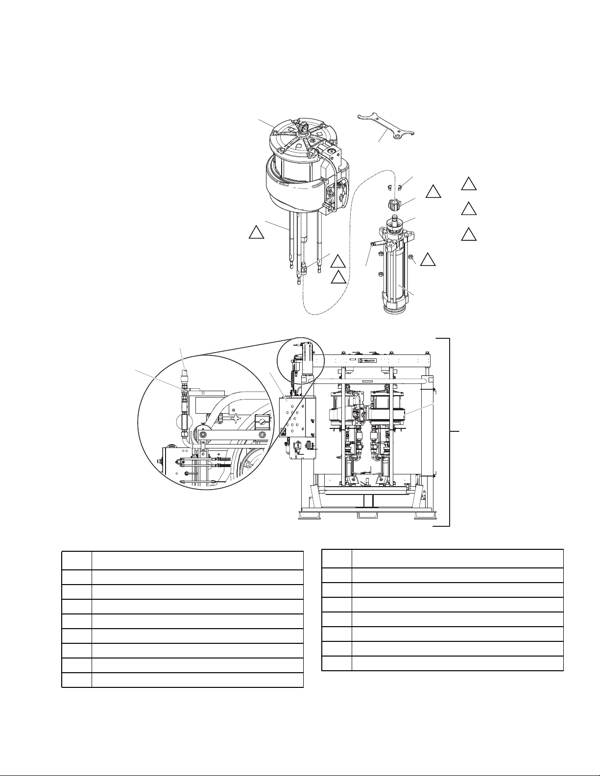
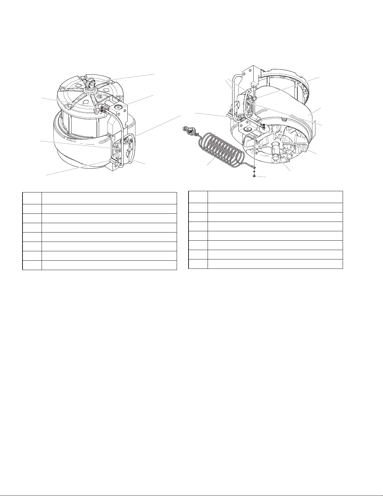
Component Identification / Pump Assembly
Component Identification / Pump Assembly
Pump Assembly Instructions:
1. Assemble (H) to (F).
Apply sealant and torque.
2. Assemble (L) to (F) and torque.
3. Assemble (G) to (L)
and hand-tighten (N).
4. Assemble (K) and
torque (J) to (H).
5. Torque (N) to (L).
&
(
)
/
1
WLD
4
.
3
-
3
Torque to 129-142 N•m
1
(95-105 ft-lb).
Apply sealant to
2
threads (102969).
Torque to 312-340 N•m
3
(230-250 ft-lb).
+
3
6
2
1
1
*
'
Ref. Description
A Pump
B Supply System
C Main Air Inlet
D Supply System Control Panel
E Bleed-Type Shutoff Valve
F* Motor, XL
G* Displacement Pump
H* Coupling Adapter
$
B
WLD
Typical Installation
Ref. Description
J* Coupling Nut
K* Coupling Collar
L* Tie Rod with Extension
N* Hex Nut
P* Packing Nut / Wet Cup
Q* Packing Nut Wrench
S* Pump Bleed Valve
* Included with this system.
3A4100E 5
Page 6
Component Identification / Pump Assembly
Motor Component Identification
''
..
%%
Ref. Description
AA Directional Air Valve
BB Air Inlet 1 in. npt(f)
CC Muffler
DD Pilot Valve
EE Manifold
FF Manual Shuttle Override Button
GG Ground Screw
$$
11
((
///
)
))
++
**
Ref. Description
HH Static Ground Cable
JJ Plug for Optional Solenoid
KK Optional Reed Switch Mount
LL External Pilot Lines
MM De-ice Bleed Air Valve
NN Lift Ring - 500 lb (363 kg) Maximum
PP Pump Drive Rod
33
00
&&
--
''
WLD
6 3A4100E
Page 7

Grounding the System
The equipment must be grounded to reduce the risk
of static sparking. Static sparking can cause fumes
to ignite or explode. Grounding provides an escape
wire for the electric current.
Pump: Use a ground wire and clamp (supplied). Verify
that the ground screw (GG) is attached and tightened
securely to the air motor. Connect the clamp (U) of the
static ground cable (HH) to a true earth ground. For a
replacement ground wire and clamp, order part 244524.
NOTE: Have qualified personnel check the resistance
between each pump and the true earth ground.
Grounding the System
Air and fluid hoses: Use only electrically conductive
hoses with a maximum of 500 ft (150 m) combined hose
length to ensure grounding continuity. Check electrical
resistance of hoses. If total resistance to ground
exceeds 29 megohms, replace the hose immediately.
Air compressor: Follow manufacturer recommendations.
Spray gun or dispensing valve: Ground through connec-
tion to a properly grounded fluid hose and pump.
NOTE: See system manual for additional grounding
information.
NOTE: Use a meter that is capable of measuring resistance at this level.
++
8
WLD
**
3A4100E 7
Page 8

Installation
Installation
Keep hands and fingers away from the follower plate,
pump inlets, and the drum when raising and lowering
the follower plate to reduce the risk of pinching or
amputating hands or fingers.
%%
++
WLD
1. Remove the air motor and pump from the system.
See the system manual for instructions.
2. Assemble ground wire (HH) to the ground screw
location on the air motor (F).
3. Remove the 45° 1 in. NPT fitting and replace it with
elbow (BB) and swivel (6) as needed. Assemble
with pipe sealant.
4. Install mounts (3) and gaskets (4). Torque to 15-18
ft-lb (20-24 N•m).
NOTE: For Uni-Drum™ systems, position the left and
right pumps as shown below.
/()73803
5,*+73803
5. Install air motor (F) onto the system. See system
manual for further instructions.
WLD
8 3A4100E
Page 9
Pressure Relief Procedure
Follow the Pressure Relief Procedure
whenever you see this symbol.
This equipment stays pressurized until pressure is
manually relieved. To help prevent serious injury from
pressurized fluid, such as skin injection, splashing fluid
and moving parts, follow the Pressure Relief Procedure when you stop dispensing and before cleaning,
checking, or servicing the equipment.
Pressure Relief Procedure
For the Supply System
See the system manual.
For the Pump
1. Disable any dispense equipment on the system.
See the system manual.
2. Close the bleed-type shutoff valve (E)
3. Open any downstream forward valves, such as the
ball seat applicators on ram assemblies that may be
part of the system. Have a container ready to catch
the drainage.
4. Open the pump bleed valve (S). NOTE: Have a container ready.
5. Leave the bleed valve open until you are ready to
spray/dispense again.
3A4100E 9
Page 10

Maintenance
Maintenance
Packing Nut / Wet-Cup
1. Fill the packing nut/wet cup (P) 1/3 full with Graco
Throat Seal Liquid (TSL).
2. Use the supplied wrench (Q) to adjust the packing
nut weekly so that it is just snug. Do NOT
over-tighten.
3
4
Disconnecting the Displacement
Pump
To reduce the risk of serious injury whenever you are
instructed to relieve pressure, always follow the Pres-
sure Relief Procedure on page 9.
1. Flush the pump if you are using flushable material.
2. Stop the pump at the bottom of its stroke.
3. Perform the Pressure Relief Procedure on page 9.
4. Disconnect the air or the hydraulic hose. Plug all
hydraulic hoses immediately to prevent the contamination of the hydraulic system. Hold the fluid outlet
fitting with a wrench to keep it from being loosened
while you disconnect the fluid hose.
5. Disconnect the displacement pump (G) from the
motor (F) as follows. Make sure to note the relative
position of the pump fluid outlet to the air or hydraulic inlet of the motor due to orientation restrictions on
the system. If the motor does not require servicing,
leave it attached to its mounting.
WLD
Flushing the Pump
To reduce the risk of serious injury, do not flush pump
with group 1 fluids as defined by Directive 2014/68/EU
(Pressure Equipment Directive).
The pump is tested with lightweight oil, which is left in to
protect the pump parts. If the fluid you are using may be
contaminated by the oil, flush it out with a compatible
flush material before using the pump.
• Flush at the lowest pressure possible. check
connectors for leaks and tighten as necessary.
• Flush with a fluid that is compatible with the fluid
being dispensed and the equipment wetted
parts.
1. Perform the Pressure Relief Procedure on page 9.
2. Set pump to lowest possible fluid pressure, and then
start the pump.
Be sure to use at least two people when lifting, moving,
or disconnecting the pump. This pump is too heavy for
one person. If you are disconnecting the displacement
pump from a motor which is still mounted (for example,
on a wall bracket), be sure to support the displacement
pump while it is being disconnected. Failure to do so
may result in the pump falling and causing injury or
property damage. Do this by securely bracing the
pump, or by having at least two people hold the pump
while another person disconnects it.
6. Using adjustable wrenches to unscrew the coupling
nut (J) from the coupling adapter (H). Remove the
coupling collars (K). Take care not to lose or drop
the collars.
7. Hold the tie rod (L) flats with a wrench to keep the
rods from turning. Unscrew the hex nuts (N) from
the tie rods extensions. Carefully remove the displacement pump (G) from the motor (F).
3. Dispense fluid into a grounded metal pail.
10 3A4100E
Page 11
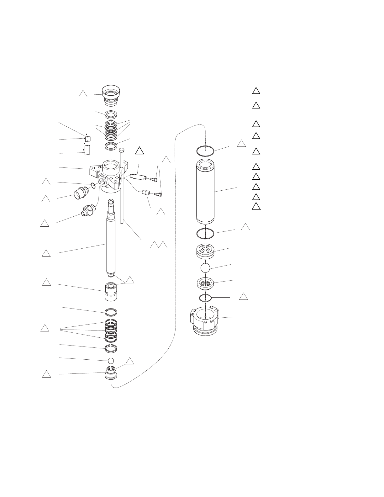
Lower Parts
25A447, 25A448, 25A449, 25A450
10
Lower Parts
Torque to 156-171 N•m (115-126 ft-lb).
1
Torque to 135-169 N•m (100-125 ft-lb).
2
For 241648, 249991, and 15F298,
limit torque to 27-40 N•m (20-30 ft-lb).
Torque to 459-481 N•m (338-354 ft-lb).
3
Torque oppositely and evenly to
4
244-264 N•m (180-195 ft-lb).
Apply anti-seize lubricant to threads
5
and mating faces.
Lubricate.
6
Apply thread lubricant.
7
Use arbor press to drive into cylinder (7).
8
Unscrew plug from valve housing and
9
clean.
10
Torque to 30-38 N•m (22-28 ft-lb).
WLD
3A4100E 11
Page 12

Lower Parts
Lower Parts List
NOTE: See the parts drawing on the previous page. Part numbers vary by lower. To find the part number used in
your lower, read down the chart to find the desired Ref. number, then read left to right to find the part number for your
lower.
*25A447 *25A448 *25A449 *25A450
Ref. Part Qty.
1 ROD, displacement 1 17L297 17L298 17L297 17L298
3 NUT, packing/ wet cup 1 24U017 24U017 24U019 24U019
4 FITTING, outlet 1 184279 184279 184387 184387
5 PACKING, o-ring 1 109213 109213 109213 109213
6 SEAL 2 184072 184072 184072 184072
7 CYLINDER 1 17L296 17L295 17L296 17L295
9 GUIDE, ball 1 184283 184283 184283 184283
10 BALL, metallic 1 102973 15C869 102973 15C869
11 GLAND, packing, male 1 184232 184232 184232 184232
12 HOUSING, valve 1 222795 222795 222795 222795
13 PACKING, vee 2 184312 184312 687057 687057
14 GUIDE, ball 1 184406 184406 184282 184282
15 HOUSING, valve 1 222794 222794 222838 222838
16 BALL, intake 1 102974 15C868 110294 15C868
17 HOUSING intake 1 184275 184275 184390 184390
19 HOUSING, outlet, pump 1 184290 184290 184389 184389
20 BOLT 6 17L291 128710 17L291 17L291
21 PLATE, designation 1 184446 184446 184446 184446
22 SCREW, drive 4 100508 100508 109202 109202
24 PLUG 1 190128 190128 190293 190293
25 GLAND, packing, female 1 184181 184181 184181 184181
26 PACKING, vee 3 109311 109311 109261 109261
27 PACKING, o-ring 1 102857 102857 102857 102857
29 GLAND, packing, male 1 184231 184231 184231 184231
30 PACKING, vee 2 184311 184311 687056 687056
33 GLAND, packing, female 1 184182 184182 184182 184182
34 PACKING, vee 3 109312 109312 109262 109262
37 PLATE, warning 1 184473 184473 184474 184474
39 BODY, bleeder 1 190126 190126 184392 184392
Carbon Steel,
Severe Duty
Carbon Steel,
MaxLife
Stainless Steel,
Severe Duty
Stainless Steel,
MaxLife
Lower
Part Body Size
*25A447 CS 1000cc SST with
*25A448 CS 1000cc SST with
*25A449 SS 1000cc SST with
*25A450 SS 1000cc SST with
Additional Warning labels are available at no cost.
Rod
Construction
Severe-Duty
Max-Life
Severe-Duty
Max-Life
Cylinder
Construction
SST with
Severe-Duty
SST with
Max-Life
SST with
Severe-Duty
SST with
Max-Life
Ball
Construction
SST E-Nickel/Cast
Silicone Nitride E-Nickel/Cast
SST SST 3 UHMWPE / 2
Silicone Nitride SST 3 UHMWPE / 2
Seat
Construction
Iron
Iron
Piston
Packings
3 PTFE/2
leather
3 PTFE / 2
Leather
Graphite PTFE
Graphite PTFE
Packings
3 PTFE/2
3 PTFE / 2
3 UHMWPE / 2
Graphite PTFE
3 UHMWPE / 2
Graphite PTFE
* Items are part of a kit, See Kits and Accessories on
Throat
leather
Leather
page 17.
12 3A4100E
Page 13

Air Motor 25A455
Lower Parts
WLD
3A4100E 13
Page 14

Lower Parts
Air Motor Parts List
Ref. Part Description Qty.
1† 24X559 COVER, bottom 1
2 24W584 COVER, top 1
3† 17L293 KIT, cylinder 1
4† 25A890 KIT, piston, motor 1
5 17L300 MANIFOLD, exhaust, XL 1
7† - - - - - BEARING, sleeve, 1.75 in. ID,
2 in. OD
8† - - - - - PACKING, u-cup, 1.75 in. ID,
2.125 in. OD
9† - - - - - SEAL, rod, wiper, 1.75 in. rod 1
10† - - - - - O-RING, piston 1
11† - - - - - RING, retaining 1
12 24X560 COVER, muffler, complete 1
13 24X562 VALVE, air, XL 1
14 109486 PACKING, o-ring 2
15 24A366 VALVE, pilot (includes 15a-15c) 2
15a 155685 PACKING, o-ring, middle 1
15b† - - - - - PACKING, u-cup, shaft 1
15c 154741 PACKING, o-ring, bottom 1
15d 197650 O-RING, buna, top 1
16 16D001 ADAPTER, lift ring 1
17 15F931 RING, lift, sst 1 9/16 thread 1
18 NXT106 BUMPER, piston (with magnet) 1
19† 25A915 KIT, bumper, top and bottom
(with screws)
21 108014 PACKING, o-ring 1
Ref. Part Description Qty.
22† - - - - - GASKET, end cap 2
23 110036 BOLT, M8 x 1.25 x 45 mm 4
24 17B389 SCREW, M8 x 1.25 x 45 mm 4
25 127582 SCREW, 5/8 11 x 8.5 in. 6
26 - - - - - FITTING, swivel 45°, 1 npt x 1 npsm 1
27 24X565 GASKET, valve, 2 pack 1
1
28 555749 FITTING, adapter, 1/8 npt(m) x JIC
1
30 17C974 CAP, manifold, air, XL 2
31 C20987 PACKING, o-ring 1
38 244524 CABLE, ground, with clamp
38a 290079 TAG, warning, grounding
39 111307 WASHER, lock, external 1
40 116343 SCREW, ground 1
42 17C776 GASKET, muffler 1
51 15F674 LABEL, safety, motor 1
52 104010 PACKING, o-ring 2
53 557832 RING, retainer, 187 basic int 2
55 128090 HOSE, coupled 2
75 123889 FITTING, elbow 1
76 C19032 SWIVEL, swivel union 1
1
Replacement Warning labels, signs, tags, and cards are
available at no cost.
† See Kits and Accessories, page 17.
(#4); 1/2 hex
(includes 38a)
(not shown)
2
1
1
14 3A4100E
Page 15

Dura-Flo 1000cc Pumps with Xtreme and XL Motors
Dura-Flo 1000cc Pumps with Xtreme and XL Motors
)
4
.
-
/
3
+
6
1
*
WLD
25A451 25A452 25A453 25A454
Ref. Description
F MOTOR, XL 24000 25A455 25A455 25A455 25A455 1
H ADAPTER, rod 184582 184582 184582 184582 1
J COLLAR, coupling 184130 184130 184130 184130 2
K NUT, coupling 184096 184096 184096 184096 1
N NUT, mach, hex 106166 106166 106166 106166 3
Q TOOL, wrench, combo 184278 184278 184278 184278 1
- ADHESIVE, anaerobic 102969 102969 102969 102969 1
L KIT, rod, tie, 1000cc 17L294 17L294 17L294 17L294 3
- MOUNT 189977 189977 189977 189977 3
- GASKET 190072 190072 190072 190072 6
C Dura-Flo 1800 (1000cc) 25A447 25A448 25A449 25A450 1
Severe Duty Max Life Sever Duty MaxLife
Carbon
Steel
Stainless
Steel
Carbon
Steel
Stainless
Steel
Qty.
3A4100E 15
Page 16

Dura-Flo 1000cc Pumps with Xtreme and XL Motors
Repair Kits
UHMWPE and PTFE Packings
Throat Packings Piston Packings
*11
25*
*35
*26
TI8389a1
36*
29*
*33
17L796 Repair Kit, for Dura-Flo 1000cc
(standard for 25A449 and 25A450)
Ref. Part Description Qty.
11 184232 GLAND, male, piston, stainless steel 1
25 184181 GLAND, female, throat, stainless steel 1
26 687056 V-PACKING, throat, graphite/PTFE 2
29 184231 GLAND, male, throat, stainless steel 1
33 184182 GLAND, female, piston, stainless steel 1
34 687057 V-PACKING, piston, graphite/PTFE 2
35 109262 V-PACKING, piston, UHMWPE 3
36 109261 V-PACKING, throat, UHMWPE 3
222845 Repair Kit, for Dura-Flo 1000cc
Ref. Part Description Qty.
11 184232 GLAND, male, piston, stainless steel 1
25 184181 GLAND, female, throat, stainless steel 1
26 109311 V-PACKING, throat, PTFE 2
29 184231 GLAND, male, throat, stainless steel 1
33 184182 GLAND, female, piston, stainless steel 1
34 109312 V-PACKING, piston, PTFE 2
35 109262 V-PACKING, piston, UHMWPE 3
36 109261 V-PACKING, throat, UHMWPE 3
34*
TI8389a2
PTFE Packings
Throat Packings Piston Packings
26*
29*
*11
*34
*33
TI8389a2
25*
TI8389a1
222846 Repair Kit, for Dura-Flo 1000cc
Ref. Part Description Qty.
11* 184232 GLAND, male, piston; sst 1
25* 184181 GLAND, female, throat; sst 1
26* 109311 V-PACKING, throat; PTFE 5
29* 184231 GLAND, male, throat, sst 1
33* 184182 GLAND, female, piston; sst 1
34* 109312 V-PACKING, piston, PTFE 5
PTFE and Leather Packings
Throat Packings Piston Packings
36*
29*
*11
*35
13*
*33
TI8389a2TI8389a1
25*
*30
222849 Repair Kit, for Dura-Flo 1000cc
(standard for 25A447 and 25A448)
Ref. Part Description Qty.
11* 184232 GLAND, male, piston; sst 1
13* 184312 V-PACKING, piston; leather 2
25* 184181 GLAND, female, throat; stainless steel 1
29* 184231 GLAND, male, throat, sst 1
30* 184311 V-PACKING, throat; leather 2
33* 184182 GLAND, female, piston; sst 1
35* 109262 V-PACKING, piston; UHMWPE 3
36* 109261 V-PACKING, throat; UHMWPE 3
222847 Leather/PTFE Backup
Conversion Kit for Dura-Flo 1000cc
11* 184232 GLAND, male, piston; stainless steel 1
13* 184312 V-PACKING, piston; leather 4
25* 184181 GLAND, female, throat; stainless steel 1
26* 109311 V-PACKING, throat; PTFE 1
29* 184231 GLAND, male, throat; stainless steel 1
30* 184311 V-PACKING, throat; leather 4
33* 184182 GLAND, female, piston; stainless steel 1
34* 109312 V-PACKING, piston; PTFE 1
17L796 Packings Repair Kit for Dura-Flo 1000cc
11* 184232 GLAND, male, piston; sst 1
13* 687056 V-PACKING, graphite/TFE Dura 2
25* 184181 GLAND, female, throat; stainless steel 1
29* 184231 GLAND, male, throat; stainless steel 1
30* 687057 V-PACKING, graphite/TFE Dura
33* 184182 GLAND, female, piston; stainless steel 1
35* 109262 V-PACKING, piston; UHMWPE 3
36* 109261 V-PACKING, throat; UHMWPE 3
16 3A4100E
Page 17

Dura-Flo 1000cc Pumps with Xtreme and XL Motors
Kits and Accessories
† XL Air Motor Repair Kits Air Valve Repair Kits
Part Description
NXT103 Lift Ring (17)
25A890 Piston/Rod Assembly Repair
Kit
-- 15G478 Bumper (18)
- - - - - Piston (4)
- - - - - Shaft, piston, Rod
24X558 Air Motor Soft Parts Repair
Kit
- - - - - O-ring, cylinder (2) (14)
-- 155885 Packing, O-ring, middle (15a)
- - - - - Packing, U-cup, shaft (15b)
-- 154741 Packing, O-ring, bottom (15c)
-- 197650 O-ring, Buna, top (15d)
- - - - - O-ring, piston (10)
- - - - - Packing, U-cup (8)
- - - - - Seal, rod (9)
- - - - - Ring, retaining (11)
- - - - - Gasket, end cap (2) (22)
- - - - - Gasket, muffler (42)
24X559 Bottom End Cap Repair Kit
- - - - - Bumper (19)
- - - - - Bearing, sleeve (7)
- - - - - Packing, U-cup (8)
- - - - - Seal, rod (9)
- - - - - Ring, retaining (11)
- - - - - Cover, bottom (1)
24X560 Muffler Repair Kit
-- 15F674 Label, warning (51)
- - - - - Foam, Dampers (46)
- - - - - Cylinder, Motor (3)
24A915 Bumper Kit
- - - - - Bumper, bottom (19)
- - - - - Bumper, top (20)
- - - - - Screw, top (3) (29)
Air Motor
Parts Ref.
Part Description
24X562 Repair, Complete Assembly
- - - - - Valve, Air, XL (13)
24X585 Kit, gasket, valve (2 pack) (27)
24X563 Repair, Valve O-rings
Accessories
Part Description
256893 Linear sensor, potted, XM
287839 Linear sensor, HLS motors
24X550 Kit, reed switch and solenoid, DataTrak, XL bracket
24X552 Kit, reed switch, DataTrak, XL bracket
iKit 17L014 1000cc Pump Assembly Parts
Part Description Qty.
184582 ADAPTER, rod 1
184130 COLLAR, coupling 2
184096 NUT, coupling 1
106166 NUT, mach, hex 3
184278 TOOL, wrench, combo 1
102969 ADHESIVE, anaerobic 1
17L294 KIT, rod, tie, 1000cc 3
189977 MOUNT 3
190072 GAKSET 6
XL Motor Kit 25A455
Part Description Qty.
- - - - - MOTOR, XL, 24000 1
244524 WIRE, ground, with clamp 1
189977 MOUNT 3
190072 GASKET 6
123889 FITTING, elbow 1
C19032 SWIVEL, union 1
110110 SEALANT, pipe 1
Air Valve
Parts Ref.
Air Motor and Lower Assembly Kits
K
Parent Assembly Item #1 Item #2 Description
†26B358 *25A455 3A4100 MOTOR, XL, 2400
†26B359 *25A447 3A4100 PUMP, RECIP, 18CM-CST, 1000CC
†26B360 *25A448 3A4100 PUMP, RECIP, 18CM-CST, 1000CC, MAX
†26B361 *25A449 3A4100 PUMP, RECIP, 18CM-SST, 1000CC
†26B362 *25A450 3A4100 PUMP, RECIP, 18CM-SST, 1000CC, MAX
NOTE: Do not order Item #1 *, must be ordered as the Parent Assembly †
3A4100E 17
Page 18

Dimensions and Mounting Hole Layouts
Dimensions and Mounting Hole Layouts
20.8'
(528.3 mm)
28.2'
(716.3 mm)
63.6'
(1615.4 mm)
42.8'
(1087.1 mm)
19.9'
(505.5 mm)
WLD
21.75 in.
(552 mm)
6.186 in.
(157.12 mm)
(4) 3/8-16 Mounting Holes
8.75 in. (222.25 mm) Ø
17.9 in.
(454 mm)
6.186 in.
(157.22 mm)
(6) M16 x 2.0 Holes
8.0 in. (203 mm) Ø
5.906 in. (150 mm) Ø
(3) 3/8-16 Mounting Studs
10.63 in. (270 mm) Ø
18 3A4100E
Page 19

Technical Specifications
Technical Specifications
Dura-Flo XL 1000cc Pumps
Models 25A451, 25A452, 25A453, 25A454
U.S. Metric
Ratio 47:1
Maximum Fluid Working Pressure 4500 psi 31 MPa, 310 bar
Maximum Air Inlet Pressure 100 psi 0.7 MPa, 7 bar
Displacement Per Cycle 0.264 gallons 1000cc
Maximum Speed 30 cpm
Maximum Pump Operating Temperature 100° F 37.8° C
Stroke Length 11.25 in. 286 mm
Air Motor Piston Effective Area
Displacement Pump Effective Area
Total Sounds Power* 98 dBA
Average Sound Pressure *+ 88.6 dBA
Air Inlet Size 1 in. npt(f)
Fluid Inlet Size 2 in. npt(f)
Fluid Outlet Size Carbon and Stainless steel lowers: 1-1/2 in. npt(m)
Weight
Carbon steel lowers: Carbon steel; chrome, zinc and electric nickel plat-
ing; 304, 404, and 17-4 PH grades of stainless steel; silicone nitride;
tungsten carbide; ductile iron; acetal; PTFE; carbon-filled PTFE; UHM-
Wetted parts
Stainless steel lowers: 304, 329, and 17-4 PH grades of stainless steel;
silicone nitride; chrome plating; tungsten carbide; acetal, PTFE; car-
132.7 in.
2.79 in.
Motor: 120 lb
Lower: 98 lb
2
2
WPE; leather
bon-filled PTFE; UHMWPE; leather
856 cm
18 cm
Motor: 54.4 kg
Lower: 44.5 kg
2
2
Not for use with group 1 fluids as defined by Directive 2014/68/EU (Pressure Equipment Directive).
Do not use fluids with a flash point exceeding the maximum operating temperature of the pump.
* Tested at 18 cpm with an inlet air pressure of 0.45 MPa (4.5 bar, 65 psi) per ISO 9614-2.
+ Measured at a distance of 1 m (3.3 ft) from equipment at a height of 1.5m (4.9 ft).
California Proposition 65
CALIFORNIA RESIDENTS
WARNING: Cancer and reproductive harm – www.P65warnings.ca.gov.
3A4100E 19
Page 20

Graco Standard Warranty
Graco warrants all equipment referenced in this document which is manufactured by Graco and bearing its name to be free from defects in
material and workmanship on the date of sale to the original purchaser for use. With the exception of any special, extended, or limited warranty
published by Graco, Graco will, for a period of twelve months from the date of sale, repair or replace any part of the equipment determined by
Graco to be defective. This warranty applies only when the equipment is installed, operated and maintained in accordance with Graco’s written
recommendations.
This warranty does not cover, and Graco shall not be liable for general wear and tear, or any malfunction, damage or wear caused by faulty
installation, misapplication, abrasion, corrosion, inadequate or improper maintenance, negligence, accident, tampering, or substitution of
non-Graco component parts. Nor shall Graco be liable for malfunction, damage or wear caused by the incompatibility of Graco equipment with
structures, accessories, equipment or materials not supplied by Graco, or the improper design, manufacture, installation, operation or
maintenance of structures, accessories, equipment or materials not supplied by Graco.
This warranty is conditioned upon the prepaid return of the equipment claimed to be defective to an authorized Graco distributor for verification of
the claimed defect. If the claimed defect is verified, Graco will repair or replace free of charge any defective parts. The equipment will be returned
to the original purchaser transportation prepaid. If inspection of the equipment does not disclose any defect in material or workmanship, repairs
will be made at a reasonable charge, which charges may include the costs of parts, labor, and transportation.
THIS WARRANTY IS EXCLUSIVE, AND IS IN LIEU OF ANY OTHER WARRANTIES, EXPRESS OR IMPLIED, INCLUDING BUT NOT
LIMITED TO WARRANTY OF MERCHANTABILITY OR WARRANTY OF FITNESS FOR A PARTICULAR PURPOSE.
Graco’s sole obligation and buyer’s sole remedy for any breach of warranty shall be as set forth above. The buyer agrees that no other remedy
(including, but not limited to, incidental or consequential damages for lost profits, lost sales, injury to person or property, or any other incidental or
consequential loss) shall be available. Any action for breach of warranty must be brought within two (2) years of the date of sale.
GRACO MAKES NO WARRANTY, AND DISCLAIMS ALL IMPLIED WARRANTIES OF MERCHANTABILITY AND FITNESS FOR A
PARTICULAR PURPOSE, IN CONNECTION WITH ACCESSORIES, EQUIPMENT, MATERIALS OR COMPONENTS SOLD BUT NOT
MANUFACTURED BY GRACO. These items sold, but not manufactured by Graco (such as electric motors, switches, hose, etc.), are subject to
the warranty, if any, of their manufacturer. Graco will provide purchaser with reasonable assistance in making any claim for breach of these
warranties.
In no event will Graco be liable for indirect, incidental, special or consequential damages resulting from Graco supplying equipment hereunder, or
the furnishing, performance, or use of any products or other goods sold hereto, whether due to a breach of contract, breach of warranty, the
negligence of Graco, or otherwise.
FOR GRACO CANADA CUSTOMERS
The Parties acknowledge that they have required that the present document, as well as all documents, notices and legal proceedings entered into,
given or instituted pursuant hereto or relating directly or indirectly hereto, be drawn up in English. Les parties reconnaissent avoir convenu que la
rédaction du présente document sera en Anglais, ainsi que tous documents, avis et procédures judiciaires exécutés, donnés ou intentés, à la suite
de ou en rapport, directement ou indirectement, avec les procédures concernées.
Graco Information
For the latest information about Graco products, visit www.graco.com.
For patent information, see www.graco.com/patents.
TO PLACE AN ORDER, contact your Graco distributor or call to identify the nearest distributor.
Phone: 612-623-6921 or Toll Free: 1-800-328-0211, Fax: 612-378-3505
All written and visual data contained in this document reflects the latest product information available at the time of publication.
GRACO INC. AND SUBSIDIARIES • P.O. BOX 1441 • MINNEAPOLIS MN 55440-1441 • USA
Copyright 2016, Graco Inc. All Graco manufacturing locations are registered to ISO 9001.
Graco reserves the right to make changes at any time without notice.
2ULJLQDOLQVWUXFWLRQV This manual contains English. MM 3A4100
Graco Headquarters: Minneapolis
International Offices: Belgium, China, Japan, Korea
www.graco.com
Revision E,February
2021
 Loading...