

Page 1
Operation, Repair, Parts
312879E
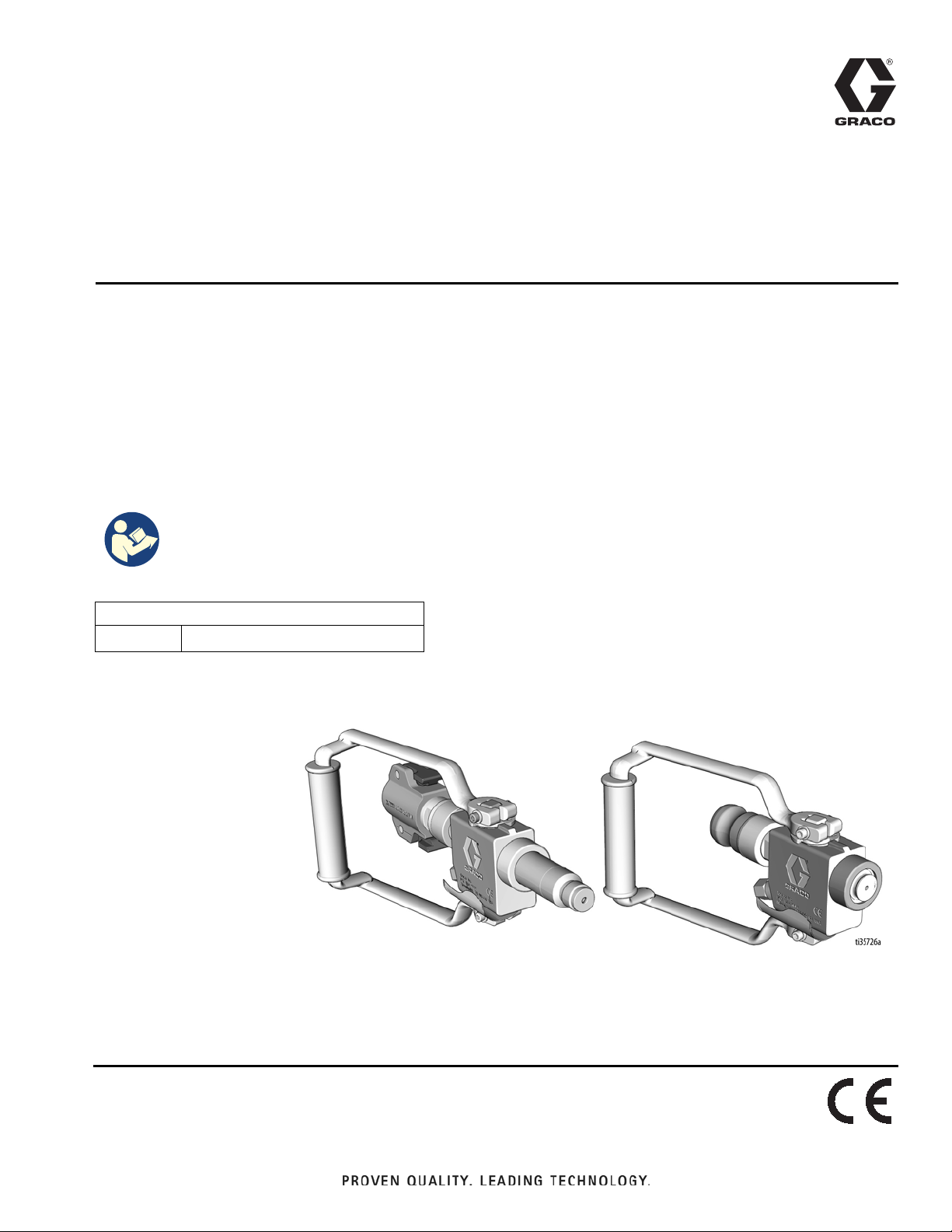
T-Max Applicator
For portable spraying of water-based materials. Can be used for application of
solvent-based materials only when solvent compatible seals are installed and solvent
compatible, conductive hoses are used. For professional use only.
Not approved for use in European explosive atmosphere locations.
Models 256383, 17Z054
1000 psi (6.9 MPa, 69 bar) Maximum Fluid Working Pressure
250 psi (1.7 MPa, 17 bar) Maximum Air Working Pressure
Important Safety Instructions
Read all warnings and instructions in this manual and in
the T-Max operation manual before using the equipment.
Save these instructions.
EN
Related Manuals:
3A6748 T-Max Operation, Repair, Parts
Page 2
Warnings
Warnings
The following warnings are for the setup, use, grounding, maintenance, and repair of this equipment. The
exclamation point symbol alerts you to a general warning and the hazard symbols refer to procedure-specific risks. When
these symbols appear in the body of this manual or on warning labels, refer back to these Warnings.
Product-specific hazard symbols and warnings not covered in this section may appear throughout the body of this manual
where applicable.
FIRE AND EXPLOSION HAZARD
Flammable fumes, such as solvent and paint fumes, in work area can ignite or explode. Paint or solvent
flowing through the equipment can cause static sparking. To help prevent fire and explosion:
• Use equipment only in well-ventilated area.
• Eliminate all ignition sources; such as pilot lights, cigarettes, portable electric lamps, and plastic drop
cloths (potential static sparking).
• Ground all equipment in the work area.
• Never spray or flush solvent at high pressure.
• Keep work area free of debris, including solvent, rags and gasoline.
• Do not plug or unplug power cords, or turn power or light switches on or off when flammable fumes are
present.
• Use only grounded hoses.
• Hold gun firmly to side of grounded pail when triggering into pail. Do not use pail liners unless they are
anti-static or conductive.
• Stop operation immediately if static sparking occurs or you feel a shock. Do not use equipment until you
identify and correct the problem.
• Keep a working fire extinguisher in the work area.
SKIN INJECTION HAZARD
High-pressure fluid from gun, hose leaks, or ruptured components will pierce skin. This may look like just a
cut, but it is a serious injury that can result in amputation. Get immediate surgical treatment.
• Do not spray without tip guard installed.
• Do not point gun at anyone or at any part of the body.
• Do not put your hand over the spray tip.
• Do not stop or deflect leaks with your hand, body, glove, or rag.
• Follow the Pressure Relief Procedure when you stop spraying and before cleaning, checking, or
servicing equipment.
• Tighten all fluid connections before operating the equipment.
• Check hoses and couplings daily. Replace worn or damaged parts immediately.
2 312879E
Page 3

Warnings
EQUIPMENT MISUSE HAZARD
Misuse can cause death or serious injury.
• Do not operate the unit when fatigued or under the influence of drugs or alcohol.
• Do not exceed the maximum working pressure or temperature rating of the lowest rated system
component. See Technical Specifications in all equipment manuals.
• Use fluids and solvents that are compatible with equipment wetted parts. See Technical Specifications
in all equipment manuals. Read fluid and solvent manufacturer’s warnings. For complete information about
your material, request Safety Data Sheets (SDSs) from distributor or retailer.
• Do not leave the work area while equipment is energized or under pressure.
• Turn off all equipment and follow the Pressure Relief Procedure when equipment is not in use.
• Check equipment daily. Repair or replace worn or damaged parts immediately with genuine
manufacturer’s replacement parts only.
• Do not alter or modify equipment. Alterations or modifications may void agency approvals and create
safety hazards.
• Make sure all equipment is rated and approved for the environment in which you are using it.
• Use equipment only for its intended purpose. Call your distributor for information.
• Route hoses and cables away from traffic areas, sharp edges, moving parts, and hot surfaces.
• Do not kink or over bend hoses or use hoses to pull equipment.
• Keep children and animals away from work area.
• Comply with all applicable safety regulations.
PRESSURIZED ALUMINUM PARTS HAZARD
Use of fluids that are incompatible with aluminum in pressurized equipment can cause serious chemical
reaction and equipment rupture. Failure to follow this warning can result in death, serious injury, or property
damage.
• Do not use 1,1,1-trichloroethane, methylene chloride, other halogenated hydrocarbon solvents or fluids
containing such solvents.
• Do not use chlorine bleach.
• Many other fluids may contain chemicals that can react with aluminum. Contact your material supplier for
compatibility.
PERSONAL PROTECTIVE EQUIPMENT
Wear appropriate protective equipment when in the work area to help prevent serious injury, including eye
injury, hearing loss, inhalation of toxic fumes, and burns. Protective equipment includes but is not limited to:
• Protective eyewear, and hearing protection.
• Respirators, protective clothing, and gloves as recommended by the fluid and solvent manufacturer.
312879E 3
Page 4
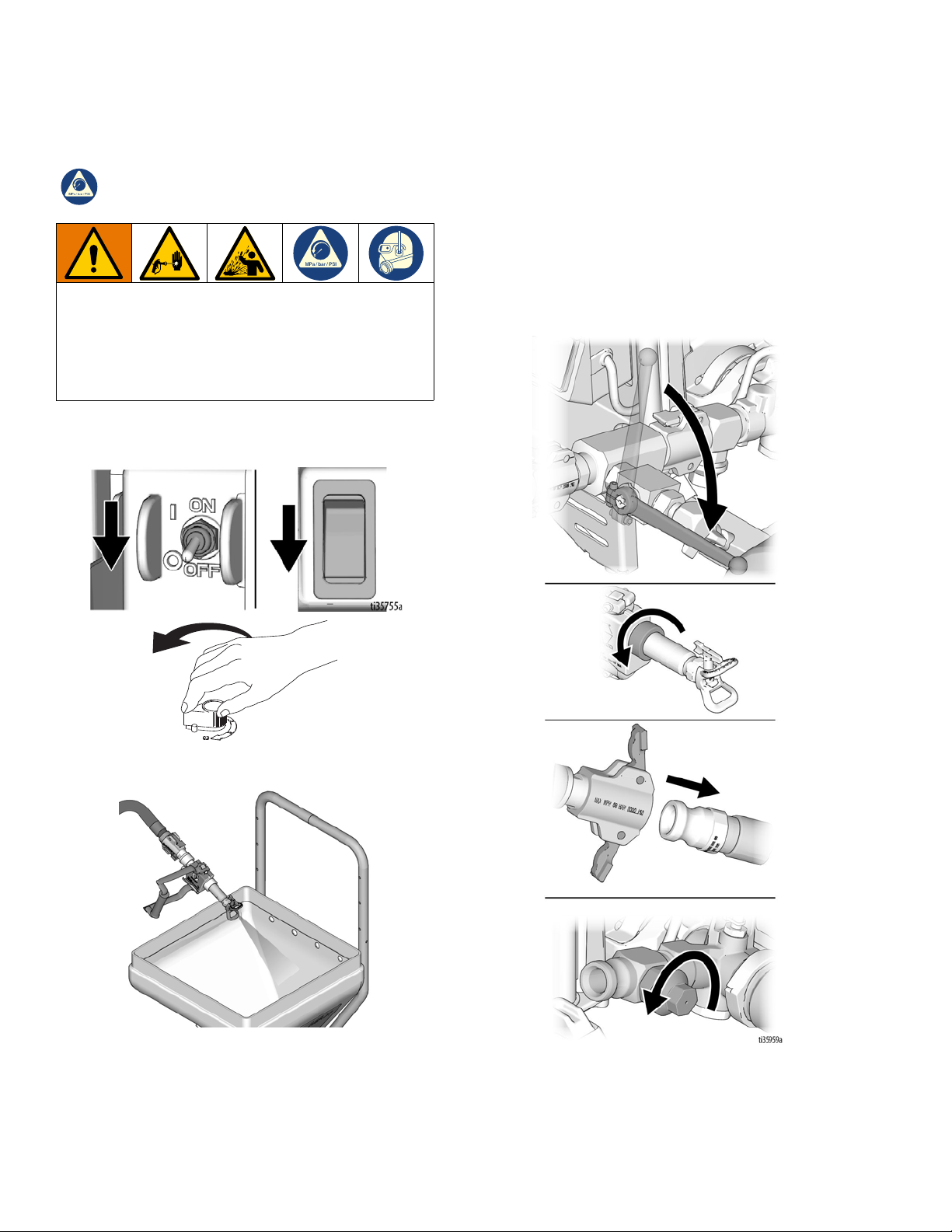
Pressure Relief Procedure
Pressure Relief Procedure
Follow the Pressure Relief Procedure whenever
you see this symbol.
This equipment stays pressurized until pressure is
manually relieved. To help prevent serious injury from
pressurized fluid, such as skin injection, splashing
fluid and moving parts, follow the Pressure Relief
Procedure when you stop spraying and before
cleaning, checking, or servicing the equipment.
1. Turn on/off switch OFF and turn pressure control
knob fully counterclockwise to OFF.
3. If you suspect the spray tip or hose is clogged or
that pressure has not been fully relieved:
a. If installed, turn prime valve down to prime
position.
b. VERY SLOWLY loosen the retaining ring (10),
hose end coupling (43), or pressure relief valve
on the sprayer to relieve pressure gradually.
2. Point applicator into hopper. Turn applicator ON.
c. Loosen the nut or coupling completely.
d. Clear the obstruction in the hose or tip.
NOTE: If pressure relief valve was used to relieve
pressure, be sure to disassemble and clean thoroughly.
4 312879E
Page 5

Flush the Equipment (Solvent-Based Materials)
To avoid fire and explosion, always ground equipment
and waste container. To avoid static sparking and
injury from splashing, always flush at the lowest
possible pressure.
• Flush before changing materials, before fluid can
dry or cure in the equipment, at the end of the day,
before storing, and before repairing equipment.
• Flush with a fluid that is compatible with the fluid
being dispensed and the equipment wetted parts.
• Flush at the lowest pressure possible. Check connectors for leaks and tighten as necessary.
• Do not leave the applicator or any parts in water or
cleaning solvents.
Flush the Equipment (Solvent-Based Materials)
1. Follow Pressure Relief Procedure, page 4.
2. Remove the spray tip and guard by loosening
retaining ring (10).
3. Hold a metal part of the gun firmly to a grounded
metal pail. Trigger the gun until clean solvent
dispenses.
4. Store in a dry location.
312879E 5
Page 6

Setup
Setup
Make sure sprayer is turned OFF and unplugged from power source. Refer to your sprayer instruction manual for priming and spray instructions.
Airless Spray Setup
Air Spray Setup
Connect Applicator to Sprayer
1. Attach supply hose to sprayer fluid outlet.
2. Attach other end of supply hose to applicator swivel
(17).
3. Install air hose to applicator check valve (8).
Connect Applicator to Sprayer
1. Attach supply hose to sprayer fluid outlet.
2. Attach other end of supply hose to applicator swivel
(17).
3. Refer to sprayer instruction manual for priming
instructions.
Install Applicator Tip and Guard
1. If equipment has recently been operated, perform
Pressure Relief Procedure, page 4.
To avoid serious injury from skin injection, do not put
your hand in front of the spray tip when installing or
removing the spray tip and tip guard.
2. Using a pencil or similar object, insert seal (20) into
back of guard (18).
4. Refer to sprayer instruction manual for priming
instructions.
Install Applicator Air Nozzle
1. If equipment has recently been operated, perform
Pressure Relief Procedure, page 4.
2. Install air nozzle (27; 37d-37g) and retainer (10).
3. Replace retainer with Fine Finish Kit (40) for finer
finishes.
3. Install guard (18) onto end of applicator (9).
4. Insert tip (19) in guard (18). Tighten retaining nut.
6 312879E
Page 7

Operation
(4) Vertical
(3) Horizontal
ti11908a
ti11909a
ti11714a
ti11794a
ti11715a
ti11793a
Airless Spray
1. Be sure the arrow shaped tip (19) faces forward
(spray).
2. Hold applicator perpendicular and approximately
40 in. (1 m) from surface. Move applicator first, then
open applicator to spray a test pattern.
3. Slowly increase pump pressure until coverage is
uniform and even (see sprayer instruction manual
for additional information).
Aligning Spray
1. Perform Pressure Relief Procedure, page 4.
Operation
UNCLOG
2. Rotate SwitchTip back to spray position. Turn
applicator ON. Spray test pattern.
SPRAY
2. Loosen guard retaining nut.
3. Align guard (18) horizontally to spray a horizontal
pattern.
4. Align guard (18) vertically to spray a vertical pattern.
Clear Tip Clog
To avoid tip clogs:
• When the applicator is not in use for extended
periods of time, keep the tip “wet” and perform
Pressure Relief Procedure, page 4.
• Keep tip clean and free of material.
1. Rotate SwitchTip to unclog position. Aim applicator
at floor and turn applicator ON. When clog clears,
turn applicator OFF.
Air Spray
1. Set material flow (see sprayer instruction manual for
additional information).
2. Spray test pattern
3. Turn air knob on and adjust, and/or select another
air nozzle, for desired pattern.
NOTE: Air continues to flow when handle is in off
position to keep material out of air passages.
Cleanup
Flush applicator after each work shift and store in a dry
location. Do not leave the applicator or any parts in
water or cleaning solvents.
312879E 7
Page 8

Parts 17Z054
Parts 17Z054
Ref Part Description Qty
1 289921
2* 15T848 PLATE, stop, valve 1
3* 289916 SPOOL, valve 1
4* 289918 KIT, o-ring and bearing 1
4a BEARING, upper 1
4b O-RING, fluid 2
4c BEARING, lower 1
4d O-RING, air 2
7 124796 O-RING 1
8 289919 KIT, check valve 1
9 15T827 HOUSING, valve 1
10 15T326 RING, retaining, nozzle 1
11 289922 FILTER, screen, texture, 18 mesh,
12 15D727 ADAPTER, GHD RAC 1
13 107110 LOCKNUT 2
14 108193 WASHER, plain 2
15 514237 SCREW, cap sch 10-32 x 1 1/2 2
17 17Y920 SWIVEL, assy, texture heavy 1
18 246215 GUARD, RAC X 1
19 HDA651 TIP, spray, RAC X (651) 1
20 246453 KIT, gasket and seat (5 sets) 1
22 15U034 TAG, Tmax handle function 1
30*† 121548 WASHER, plain 1
31*† 121549 RING, retaining, E-ring 1
33 277789 SUPPORT, filter 2
34 15U687 SEAL, adapter, filter, texture 1
HANDLE, valve, includes 2, 13, 14, 15
includes 33
Ref Part Description Qty
35 289923 FILTER, screen, texture, 30 mesh,
1
36* 289917 SEAT, spool, valve, includes 7 1
37 17Z185 KIT, accessories, air assist 1
37a 112779 VALVE, needle 1
37b 156823 FITTING, union, swivel 1
37c 15C899 HOSE, cpld, air, 9.5mm x 15m 1
37d 248524 NOZZLE, 4mm 1
37e 248525 NOZZLE, 6mm 1
37f 248526 NOZZLE, 8mm 1
37g 248527 NOZZLE, 10mm 1
37h 15U027 HOSE, air, cpld 1
37i 169967 FITTING, line air 1
1
37j 17Y924 NUT, retaining 1
37k 17Z274 ADAPTER, housing 1
37l 24S114 TIP, disk, spray, W4, hardened 1
37m 24S115 TIP, disk, spray, W6, hardened 1
37n 24S116 TIP, disk, spray, W8, hardened 1
37o 24S117 TIP, disk, spray, W10, hardened 1
37p 24S118 TIP, disk, spray, W12, hardened 1
37q 24S119 TIP, disk, spray, WXL, hardened 1
37r 248888 NOZZLE, 3 mm 1
42 15U368 NUT, cap 1
43 289874 COUPLER, female 1
44 15X791 PLUG, air passage 1
* Included in Spool Repair Kit 289916
† Included in O-ring and Bearing Kit 289918
includes 33
1
8 312879E
Page 9

Parts 256383
13
1
14
15
2
4a
4b
4c
3
4d
27
33
34
10
19
20
18
12
31
30
11,35
9
17
7
36
8
40
ti11785a
41
42
‡
Parts 256383
Ref Part Description Qty
1 289921
HANDLE, valve, includes 2, 13, 14, 15
2* 15T848 PLATE, stop, valve 1
3* 289916 SPOOL, valve 1
4* 289918 KIT, o-ring and bearing 1
4a BEARING, upper 1
4b O-RING, fluid 2
4c BEARING, lower 1
4d O-RING, air 2
7 111027 O-RING 1
8 289919 KIT, check valve 1
9 15T827 HOUSING, valve 1
10 15T326 RING, retaining, nozzle 1
11 289922 FILTER, screen, texture, 18 mesh,
includes 33
12 15D727 ADAPTER, GHD RAC 1
13 107110 LOCKNUT 2
14 108193 WASHER, plain 2
15 514237 SCREW, cap sch 10-32 x 1 1/2 2
17 289920 SWIVEL, assy, texture heavy 1
Ref Part Description Qty
18 246215 GUARD, RAC X 1
1
19 HDA651 TIP, spray, RAC X (651) 1
20 246453 KIT, gasket and seat (5 sets) 1
27 248524 NOZZLE, 4 mm, rnd 1
30*† 121548 WASHER, plain 1
31*† 121549 RING, retaining, E-ring 1
33 277789 SUPPORT, filter 2
34 15U687 SEAL, adapter, filter, texture 1
35 289923 FILTER, screen, texture, 30 mesh,
includes 33
36* 289917 SEAT, spool, valve, includes 7 1
40 287227 KIT, Accessory, Tex, Fine Finish 1
41 15U027 HOSE, air, extension 1
1
42 15U368 NUT, cap 1
* Included in Spool Repair Kit 289916
† Included in O-ring and Bearing Kit 289918
‡ This applicator requires Graco coupler 289874
1
312879E 9
Page 10

Spool Valve Repair
Spool Valve Repair
Before performing any maintenance on applicator, read
all warnings on front cover of this manual and performd
Pressure Relief Procedure, page 4.
Spool Valve Removal
NOTE: Spool (3) and/or seat (36) may be rotated 180°
for extended life if they are not worn through completely.
1. Remove swivel (17), o-ring (7) and seat (36).
2. Remove nut (13), screw (15), washer (14) and
handle (1). Remove plate (2), clip (31) and washer
(30).
3. Remove spool (3) from housing (9).
Spool Valve Installation
1. Apply grease (supplied with Kits 289916 and
289918) to spool, o-rings and bearings and inside of
housing.
2. Assemble o-rings and bearings onto spool. Align
bearing (4a, 4c) gaps away from ports in housing.
3. Install spool in housing. Secure with washer (30),
and clip (31).
4. Install plate (2) onto spool (note location of
orientation hole). Install handle with screw, washer
and nut.
5. Apply grease to o-ring (7). Install seat (36), o-ring
(7) and swivel (17).
Technical Data
Maximum fluid working pressure 1000 psi (6.9 MPa, 69 bar)
Maximum air working pressure 250 psi (1.7 MPa, 17 bar)
Air Requirements 30 scfm (0.84 m3/min) Maximum
Fluid Inlet Size 1 in.(m) cam and groove (Graco HP)
Air Inlet Size 1/4 npsm(m)
Wetted Parts Aluminum, stainless steel, PE, POM, polyurethane, nitrile, nylon, PVC, tungsten carbide
Weight † 2.9 lb (1,3 kg)
Height 5.8 in. (14,7 cm)
Width 7.0 in. (17,8 cm)
Length † 12.7 in. (32,3 cm)
Sound Data without Air (applicator
only):
Sound Pressure Level 84dB(A)*
Sound Power Level 83dB(A)*
Sound Data with Air (applicator only):
Sound Pressure Level 118dB(A)*
Sound Power Level 118dB(A)*
* Spraying simulated acoustical texture under typical conditions as specified by the material manufacturer.
† Airless configuration
10 312879E
Page 11

Graco Standard Warranty
Graco Standard Warranty
Graco warrants all equipment referenced in this document which is manufactured by Graco and bearing its name to
be free from defects in material and workmanship on the date of sale to the original purchaser for use. With the
exception of any special, extended, or limited warranty published by Graco, Graco will, for a period of twelve months
from the date of sale, repair or replace any part of the equipment determined by Graco to be defective. This warranty
applies only when the equipment is installed, operated and maintained in accordance with Graco’s written
recommendations.
This warranty does not cover, and Graco shall not be liable for general wear and tear, or any malfunction, damage or
wear caused by faulty installation, misapplication, abrasion, corrosion, inadequate or improper maintenance,
negligence, accident, tampering, or substitution of non-Graco component parts. Nor shall Graco be liable for
malfunction, damage or wear caused by the incompatibility of Graco equipment with structures, accessories,
equipment or materials not supplied by Graco, or the improper design, manufacture, installation, operation or
maintenance of structures, accessories, equipment or materials not supplied by Graco.
This warranty is conditioned upon the prepaid return of the equipment claimed to be defective to an authorized Graco
distributor for verification of the claimed defect. If the claimed defect is verified, Graco will repair or replace free of
charge any defective parts. The equipment will be returned to the original purchaser transportation prepaid. If
inspection of the equipment does not disclose any defect in material or workmanship, repairs will be made at a
reasonable charge, which charges may include the costs of parts, labor, and transportation.
THIS WARRANTY IS EXCLUSIVE, AND IS IN LIEU OF ANY OTHER WARRANTIES, EXPRESS OR IMPLIED,
INCLUDING BUT NOT LIMITED TO WARRANTY OF MERCHANTABILITY OR WARRANTY OF FITNESS FOR A
PARTICULAR PURPOSE.
Graco’s sole obligation and buyer’s sole remedy for any breach of warranty shall be as set forth above. The buyer
agrees that no other remedy (including, but not limited to, incidental or consequential damages for lost profits, lost
sales, injury to person or property, or any other incidental or consequential loss) shall be available. Any action for
breach of warranty must be brought within two (2) years of the date of sale.
GRACO MAKES NO WARRANTY, AND DISCLAIMS ALL IMPLIED WARRANTIES OF MERCHANTABILITY AND
FITNESS FOR A PARTICULAR PURPOSE, IN CONNECTION WITH ACCESSORIES, EQUIPMENT, MATERIALS
OR COMPONENTS SOLD BUT NOT MANUFACTURED BY GRACO. These items sold, but not manufactured by
Graco (such as electric motors, switches, hose, etc.), are subject to the warranty, if any, of their manufacturer. Graco
will provide purchaser with reasonable assistance in making any claim for breach of these warranties.
In no event will Graco be liable for indirect, incidental, special or consequential damages resulting from Graco
supplying equipment hereunder, or the furnishing, performance, or use of any products or other goods sold hereto,
whether due to a breach of contract, breach of warranty, the negligence of Graco, or otherwise.
FOR GRACO CANADA CUSTOMERS
The Parties acknowledge that they have required that the present document, as well as all documents, notices and
legal proceedings entered into, given or instituted pursuant hereto or relating directly or indirectly hereto, be drawn
up in English. Les parties reconnaissent avoir convenu que la rédaction du présente document sera en Anglais, ainsi
que tous documents, avis et procédures judiciaires exécutés, donnés ou intentés, à la suite de ou en rapport,
directement ou indirectement, avec les procédures concernées.
312879E 11
Page 12

Graco Information
For the latest information about Graco products, visit www.graco.com.
For patent information, see www.graco.com/patents.
TO PLACE AN ORDER, contact your Graco distributor or call 1-800-690-2894 to identify the nearest distributor.
All written and visual data contained in this document reflects the latest product information available at the time of publication.
GRACO INC. AND SUBSIDIARIES • P.O. BOX 1441 • MINNEAPOLIS MN 55440-1441 • USA
Copyright 2008, Graco Inc. All Graco manufacturing locations are registered to ISO 9001.
Graco reserves the right to make changes at any time without notice.
Original instructions. This manual contains English. MM 312879
International Offices: Belgium, China, Japan, Korea
Graco Headquarters: Minneapolis
www.graco.com
Revision
E, April 2019
 Loading...