

Page 1
Operation, Repair, Parts
www.graco.com/techsupport
?? ??
T-Max™ 506/657/6912
3A6748B
Texture Sprayer
For portable spraying of water-based materials. Can be used for application of
solvent-based materials only when solvent compatible seals are installed and
solvent compatible, conductive hoses are used. For professional use only.
Not approved for use in European explosive atmosphere locations.
T-Max 506: 50 bar (5 MPa, 725 psi) Maximum Working Pressure
T-Max 657: 65 bar (6.5 MPa, 940 psi) Maximum Working Pressure
T-Max 6912: 69 bar (6.9 MPa, 1000 psi) Maximum Working Pressure
See page 4-6 for model information.
Important Safety Instructions
Read all warnings and instructions in this manual and related manuals before using
the equipment. Be familiar with the controls and the proper usage of the equipment.
Save these instructions.
STX Trigger Gun 3A6746 Bag Roller Kits 312790, 3A4995
T-Max Remote Switch Kit 3A6784 T-Max Applicator 312879
PrimeValve Accessory Kit 3A6785 Free Flow Applicator 313537
Vibra-Flo T-Max 3A6909 Inline Applicator 309495
Air Manifold Kit 3A6839
Related Manuals
EN
Page 2

Contents
Models . . . . . . . . . . . . . . . . . . . . . . . . . . . . . . . . . . . . . . . . . . . . . . . . . . . . . . 4
Warnings . . . . . . . . . . . . . . . . . . . . . . . . . . . . . . . . . . . . . . . . . . . . . . . . . . . . 7
Component Identification 506 . . . . . . . . . . . . . . . . . . . . . . . . . . . . . . . . . . 11
Component Identification 657 . . . . . . . . . . . . . . . . . . . . . . . . . . . . . . . . . . 12
Component Identification 6912 . . . . . . . . . . . . . . . . . . . . . . . . . . . . . . . . . 13
Component Identification . . . . . . . . . . . . . . . . . . . . . . . . . . . . . . . . . . . . . . 14
Pump Control Settings . . . . . . . . . . . . . . . . . . . . . . . . . . . . . . . . . . . . . . . . 15
T-Max 506/657 . . . . . . . . . . . . . . . . . . . . . . . . . . . . . . . . . . . . . . . . . . . . 15
T-Max 6912 . . . . . . . . . . . . . . . . . . . . . . . . . . . . . . . . . . . . . . . . . . . . . . . 15
Operation . . . . . . . . . . . . . . . . . . . . . . . . . . . . . . . . . . . . . . . . . . . . . . . . 15
Preparation . . . . . . . . . . . . . . . . . . . . . . . . . . . . . . . . . . . . . . . . . . . . . . . . . 16
Grounding . . . . . . . . . . . . . . . . . . . . . . . . . . . . . . . . . . . . . . . . . . . . . . . . 16
Solvent-Based Materials . . . . . . . . . . . . . . . . . . . . . . . . . . . . . . . . . . . . . 16
Amp Switch . . . . . . . . . . . . . . . . . . . . . . . . . . . . . . . . . . . . . . . . . . . . . . . 16
Extension Cords . . . . . . . . . . . . . . . . . . . . . . . . . . . . . . . . . . . . . . . . . . . 17
Mixing Material . . . . . . . . . . . . . . . . . . . . . . . . . . . . . . . . . . . . . . . . . . . . 17
Hose Lubrication Mixing Instructions . . . . . . . . . . . . . . . . . . . . . . . . . . . 18
Pressure Relief Procedure . . . . . . . . . . . . . . . . . . . . . . . . . . . . . . . . . . . 19
Setup . . . . . . . . . . . . . . . . . . . . . . . . . . . . . . . . . . . . . . . . . . . . . . . . . . . . . . 21
Start Up - Airless . . . . . . . . . . . . . . . . . . . . . . . . . . . . . . . . . . . . . . . . . . . . . 24
Spray Tip Installation . . . . . . . . . . . . . . . . . . . . . . . . . . . . . . . . . . . . . . . 26
Clear Spray Tip Clog . . . . . . . . . . . . . . . . . . . . . . . . . . . . . . . . . . . . . . . 27
Start Up - Air Assist . . . . . . . . . . . . . . . . . . . . . . . . . . . . . . . . . . . . . . . . . . 28
Start Up - Air Assist STX Gun . . . . . . . . . . . . . . . . . . . . . . . . . . . . . . . . . . 30
Operation . . . . . . . . . . . . . . . . . . . . . . . . . . . . . . . . . . . . . . . . . . . . . . . . . . . 32
Cleanup . . . . . . . . . . . . . . . . . . . . . . . . . . . . . . . . . . . . . . . . . . . . . . . . . . . . 33
Troubleshooting . . . . . . . . . . . . . . . . . . . . . . . . . . . . . . . . . . . . . . . . . . . . . 39
Repair . . . . . . . . . . . . . . . . . . . . . . . . . . . . . . . . . . . . . . . . . . . . . . . . . . . . . . 43
Control Board Diagnostics . . . . . . . . . . . . . . . . . . . . . . . . . . . . . . . . . . . 43
Control Board Removal 506/657 . . . . . . . . . . . . . . . . . . . . . . . . . . . . . . 45
Control Board Installation 506, 657 . . . . . . . . . . . . . . . . . . . . . . . . . . . . 47
Control Board Removal 6912 . . . . . . . . . . . . . . . . . . . . . . . . . . . . . . . . . 49
Control Board Installation 6912 . . . . . . . . . . . . . . . . . . . . . . . . . . . . . . . 51
Pump Removal . . . . . . . . . . . . . . . . . . . . . . . . . . . . . . . . . . . . . . . . . . . . 54
Pump Installation . . . . . . . . . . . . . . . . . . . . . . . . . . . . . . . . . . . . . . . . . . 56
Pump Repair 506/657 . . . . . . . . . . . . . . . . . . . . . . . . . . . . . . . . . . . . . . . 58
Pump Repair 6912 . . . . . . . . . . . . . . . . . . . . . . . . . . . . . . . . . . . . . . . . . 60
Cross-Section Reference / Pump Ball Identification 6912 . . . . . . . . . . . 63
Motor Removal . . . . . . . . . . . . . . . . . . . . . . . . . . . . . . . . . . . . . . . . . . . . 64
Motor Installation . . . . . . . . . . . . . . . . . . . . . . . . . . . . . . . . . . . . . . . . . . 65
Recycling and Disposal at End of Life . . . . . . . . . . . . . . . . . . . . . . . . . . 66
2 3A6748B
Page 3

Parts - Hopper Frame . . . . . . . . . . . . . . . . . . . . . . . . . . . . . . . . . . . . . . . . . 68
Parts List - Frame . . . . . . . . . . . . . . . . . . . . . . . . . . . . . . . . . . . . . . . . . 69
Parts - Power Module 506/657 . . . . . . . . . . . . . . . . . . . . . . . . . . . . . . . . . . 70
Parts List - Power Module 506/657 . . . . . . . . . . . . . . . . . . . . . . . . . . . . 71
Parts - Power Module 6912 . . . . . . . . . . . . . . . . . . . . . . . . . . . . . . . . . . . . 72
Parts List - Power Module 6912 . . . . . . . . . . . . . . . . . . . . . . . . . . . . . . . 73
Parts - Pump 289555 (506) . . . . . . . . . . . . . . . . . . . . . . . . . . . . . . . . . . . . . 74
Parts List - Pump . . . . . . . . . . . . . . . . . . . . . . . . . . . . . . . . . . . . . . . . . . 74
Parts - Pump 289556 (657) . . . . . . . . . . . . . . . . . . . . . . . . . . . . . . . . . . . . . 75
Parts List - Pump . . . . . . . . . . . . . . . . . . . . . . . . . . . . . . . . . . . . . . . . . . 75
Parts - Pump 25E668 (6912) . . . . . . . . . . . . . . . . . . . . . . . . . . . . . . . . . . . 76
Parts List - Pump 25E668 (6912) . . . . . . . . . . . . . . . . . . . . . . . . . . . . . . 77
Parts - Control Box 506/657 . . . . . . . . . . . . . . . . . . . . . . . . . . . . . . . . . . . . 78
Parts List - Control Box 506/657 . . . . . . . . . . . . . . . . . . . . . . . . . . . . . . 79
Parts - Control Box 6912 . . . . . . . . . . . . . . . . . . . . . . . . . . . . . . . . . . . . . . 80
Parts List - Control Box . . . . . . . . . . . . . . . . . . . . . . . . . . . . . . . . . . . . . 80
Wiring Diagrams . . . . . . . . . . . . . . . . . . . . . . . . . . . . . . . . . . . . . . . . . . . . . 81
506/657 . . . . . . . . . . . . . . . . . . . . . . . . . . . . . . . . . . . . . . . . . . . . . . . . . 81
6912 - US . . . . . . . . . . . . . . . . . . . . . . . . . . . . . . . . . . . . . . . . . . . . . . . . 82
6912 - UK . . . . . . . . . . . . . . . . . . . . . . . . . . . . . . . . . . . . . . . . . . . . . . . . 83
Technical Specifications . . . . . . . . . . . . . . . . . . . . . . . . . . . . . . . . . . . . . . 84
CALIFORNIA PROPOSITION 65 . . . . . . . . . . . . . . . . . . . . . . . . . . . . . 86
Graco Standard Warranty . . . . . . . . . . . . . . . . . . . . . . . . . . . . . . . . . . . . . 87
Graco Information . . . . . . . . . . . . . . . . . . . . . . . . . . . . . . . . . . . . . . . . . . . 88
3A6748B 3
Page 4
Models
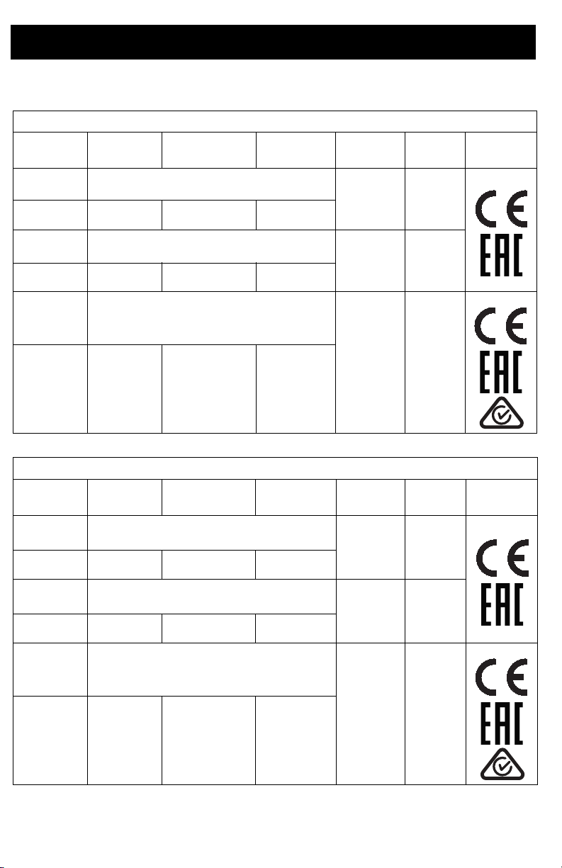
Models
Model Hoses Applicator
T-MAX 506
17 Gallon
Hopper
Power
Cord
VAC
17Z169
17X980
17Z170
17X982
17Z291 Bare Unit
17X981
3m whip
5m
3m whip
5m
3m whip
5m
Bare Unit
T-Max Applicator
Bare Unit
T-Max Applicator
T-Max Applicator
Model Hoses Applicator
17Z171
17X983
17Z172
17X985
3m whip
5m
3m whip
5m
Bare Unit
T-Max Applicator
Bare Unit
T-Max Applicator
T-MAX 657
17 Gallon
Hopper
CEE 7/7
UK
Multi-Cord
Power
Cord
CEE 7/7
UK
230VAC
110VAC
230VAC
VAC
230VAC
110VAC
17Z292 Bare Unit
230VAC
17X984
3m whip
5m
T-Max Applicator
Multi-Cord
4 3A6748B
Page 5
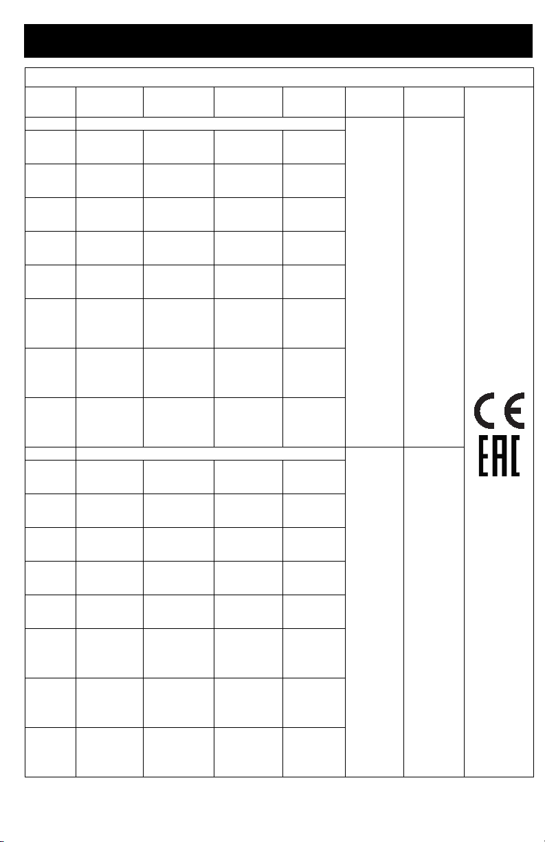
Model Hoses Applicator
17Z173 Bare Unit
17Z626
17X986
17Z532
17X990
17X993
17Z285
17Z288
17Z529
17Z174 Bare Unit
17Z629
17X988
17Z534
17X992
17Z282
17Z287
17Z290
17Z531
3m whip
5m
10m
3m whip
5m
10m
3m whip
5m
10m
3m whip
5m
10m
3m whip
5m
10m
3m whip
5m
10m
3m whip
5m
10m
3m whip
5m
10m
3m whip
5m
10m
3m whip
5m
10m
3m whip
5m
10m
3m whip
5m
10m
3m whip
5m
10m
3m whip
5m
10m
3m whip
5m
10m
3m whip
5m
10m
T-Max
Applicator
Inline
Applicator
Free-Flow
Applicator
STX
Spray Gun
T-Max
Applicator
Free-Flow
Applicator
T-Max
Applicator
STX
Spray Gun
T-Max
Applicator
Pole
Applicator
T-Max
Applicator
Inline
Applicator
Free-Flow
Applicator
STX
Spray Gun
T-Max
Applicator
Free-Flow
Applicator
T-Max
Applicator
STX
Spray Gun
T-Max
Applicator
Pole
Applicator
T-MAX 6912
25 Gallon
Hopper
Air
Manifold
Power
Cord
CEE 7/7
UK
Models
VAC
230VAC
110VAC
3A6748B 5
Page 6
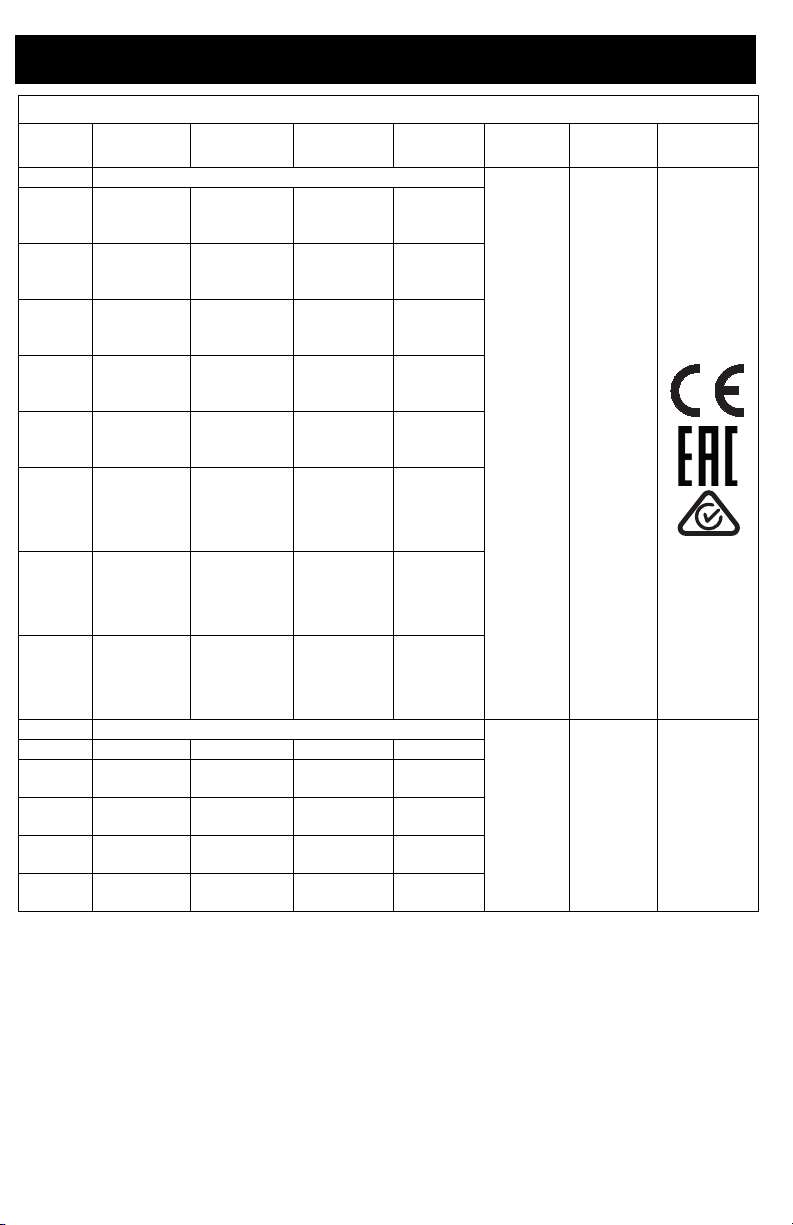
Models
T-MAX 6912 continued
Model Hoses Applicator
17Z293 Bare Unit
17Z628
17X987
17Z533
17X991
17X994
17Z286
17Z289
17Z530
17Z175
17Z630
17X989
17Z283
17Z284
17Z703
3m whip
5m
10m
3m whip
5m
10m
3m whip
5m
10m
3m whip
5m
10m
3m whip
5m
10m
3m whip
5m
10m
3m whip
5m
10m
3m whip
5m
10m
50’
9’ whip
50’
9’ whip
100’
9’ whip
100’
9’ whip
T-Max
Applicator
Inline
Applicator
Free-Flow
Applicator
STX Spray
Gun
T-Max
Applicator
Free-Flow
Applicator
T-Max
Applicator
STX SPray
Gun
T-Max
Applicator
Pole
Applicator
Bare Unit
T-Max
Applicator
STX Spray
Gun
STX Spray
Gun
STX Spray
Gun
25 Gallon
Hopper
Air
Manifold
Power
Cord
Multi-Cord
NA
VAC
230VAC
120VAC
6 3A6748B
Page 7
Warnings
WARNING
230V
110V UK
120V
Warnings
The following warnings are for the setup, use, grounding, maintenance, and repair of this
equipment. The exclamation point symbol alerts you to a general warning and the hazard
symbols refer to procedure-specific risks. When these symbols appear in the body of this
manual or on warning labels, refer back to these Warnings. Product-specific hazard symbols
and warnings not covered in this section may appear throughout the body of this manual
where applicable.
GROUNDING
This product must be grounded. In the event of an electrical short circuit, grounding
reduces the risk of electric shock by providing an escape wire for the electric current.
This product is equipped with a cord having a grounding wire with an appropriate
grounding plug. The plug must be plugged into an outlet that is properly installed and
grounded in accordance with all local codes and ordinances.
• Improper installation of the grounding plug is able to result in a risk of electric
shock.
• When repair or replacement of the cord or plug is required, do not connect the
grounding wire to either flat blade terminal.
• The wire with insulation having an outer surface that is green with or without
yellow stripes is the grounding wire.
• Check with a qualified electrician or serviceman when the grounding instructions
are not completely understood, or when in doubt as to whether the product is
properly grounded.
• Do not modify the plug provided; if it does not fit the outlet, have the proper outlet
installed by a qualified electrician.
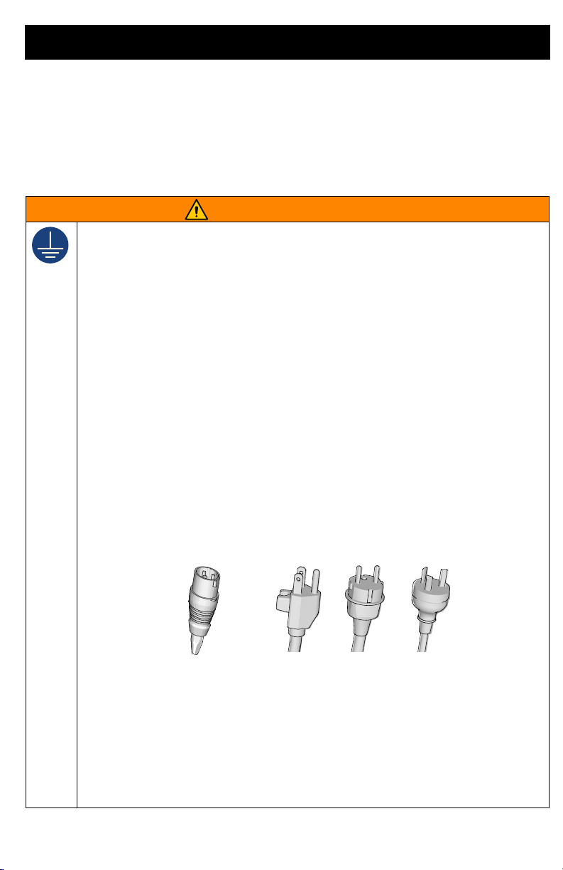
• This product is for use on a nominal 110V or 230V circuit and has a grounding
plug similar to the plugs illustrated in the figure below.
ti24583a
• Only connect the product to an outlet having the same configuration as the plug.
• Do not use an adapter with this product.
Extension Cords:
•
Use only a 3-wire extension cord that has a grounding plug and a grounding
receptacle that accepts the plug on the product.
• Make sure your extension cord is not damaged. If an extension cord is necessary
use 12 AWG (2.5mm) minimum to carry the current that the product draws.
• An undersized cord results in a drop in line voltage and loss of power and
overheating.
3A6748B 7
Page 8
Warnings
WARNING
FIRE AND EXPLOSION HAZARD
Flammable fumes, such as solvent and material fumes, in work area can ignite or
explode. To help prevent fire and explosion:
• Do not spray flammable or combustible materials near an open flame or sources
of ignition such as cigarettes, motors, and electrical equipment.
• Material or solvent flowing through the equipment is able to result in static
electricity. Static electricity creates a risk of fire or explosion in the presence of
material or solvent fumes. All parts of the spray system, including the pump, hose
assembly, spray gun, and objects in and around the spray area shall be properly
grounded to protect against static discharge and sparks. Use Graco conductive
or grounded high-pressure airless material sprayer hoses.
• Verify that all containers and collection systems are grounded to prevent static
discharge. Do not use pail liners unless they are anti-static or conductive.
• Connect to a grounded outlet and use grounded extensions cords. Do not use
a 3-to-2 adapter.
• Do not use a material or a solvent containing halogenated hydrocarbons.
• Do not spray flammable or combustible liquids in a confined area.
• Keep spray area well-ventilated. Keep a good supply of fresh air moving through
the area.
• Sprayer generates sparks. Keep pump assembly in a well ventilated area a least
20 feet (6.1 m) from the spray area when spraying, flushing, cleaning, or
servicing. Do not spray pump assembly.
• Do not smoke in the spray area or spray where sparks or flame is present.
• Do not operate light switches, engines, or similar spark producing products in the
spray area.
• Keep area clean and free of material or solvent containers, rags, and other
flammable materials.
• Know the contents of the materials and solvents being sprayed. Read all Safety
Data Sheets (SDSs) and container labels provided with the materials and
solvents. Follow the material and solvents manufacturer’s safety instructions.
• Keep a working fire extinguisher in the work area.
ELECTRIC SHOCK HAZARD
This equipment must be grounded. Improper grounding, setup, or usage of the
system can cause electric shock.
• Turn off and disconnect power cord before servicing equipment.
• Connect only to grounded electrical outlets.
• Use only 3-wire extension cords.
• Ensure ground prongs are intact on power and extension cords.
• Do not expose to rain. Store indoors.
• Wait five minutes after disconnecting power cord before servicing.
8 3A6748B
Page 9
Warnings
WARNING
SKIN INJECTION HAZARD
High-pressure spray is able to inject toxins into the body and cause serious injury
that can result in amputation. In the event that injection occurs, get immediate
surgical treatment.
• Do not aim the gun at, or spray any person or animal.
• Keep hands and other body parts away from the discharge. For example, do not
try to stop leaks with any part of the body.
• Always use the spray tip guard. Do not spray without spray tip guard in place.
• Use Graco spray tips.
• Use caution when cleaning and changing spray tips. In the case where the spray
tip clogs while spraying, follow the Pressure Relief Procedure for turning off the
unit and relieving the pressure before removing the spray tip to clean.
• Equipment maintains pressure after power is shut off. Do not leave the
equipment energized or under pressure while unattended. Follow the Pressure
Relief Procedure when the equipment is unattended or not in use, and before
servicing, cleaning, or removing parts.
• Check hoses and parts for signs of damage. Replace any damaged hoses or
parts.
• This system is capable of producing 1000 psi (69 bar, 6.9 MPa). Use Graco parts
or accessories that are rated a minimum of 1000 psi (69 bar, 6.9 MPa).
• Verify that all connections are secure before operating the unit.
• Know how to stop the unit and bleed pressure quickly. Be thoroughly familiar with
the controls.
PRESSURIZED ALUMINUM PARTS HAZARD
Use of fluids that are incompatible with aluminum in pressurized equipment can
cause serious chemical reaction and equipment rupture. Failure to follow this
warning can result in death, serious injury, or property damage.
• Do not use 1,1,1-trichloroethane, methylene chloride, other halogenated
hydrocarbon solvents or fluids containing such solvents.
• Do not use chlorine bleach.
• Many other fluids may contain chemicals that can react with aluminum. Contact
your material supplier for compatibility.
3A6748B 9
Page 10
Warnings
WARNING
EQUIPMENT MISUSE HAZARD
Misuse can cause death or serious injury.
• Do not operate the unit when fatigued or under the influence of drugs or alcohol.
• Do not exceed the maximum working pressure or temperature rating of the
lowest rated system component. See Technical Specifications in all
equipment manuals.
• Use fluids and solvents that are compatible with equipment wetted parts. See
Technical Specifications in all equipment manuals. Read fluid and solvent
manufacturer’s warnings. For complete information about your material, request
Safety Data Sheets (SDSs) from distributor or retailer.
• Do not leave the work area while equipment is energized or under pressure.
• Turn off all equipment and follow the Pressure Relief Procedure when
equipment is not in use.
• Check equipment daily. Repair or replace worn or damaged parts immediately
with genuine manufacturer’s replacement parts only.
• Do not alter or modify equipment. Alterations or modifications may void agency
approvals and create safety hazards.
• Make sure all equipment is rated and approved for the environment in which you
are using it.
• Use equipment only for its intended purpose. Call your distributor for information.
• Route hoses and cables away from traffic areas, sharp edges, moving parts, and
hot surfaces.
• Do not kink or over bend hoses or use hoses to pull equipment.
• Keep children and animals away from work area.
• Comply with all applicable safety regulations.
MOVING PARTS HAZARD
Moving parts can pinch, cut, or amputate fingers and other body parts.
• Keep clear of moving parts.
• Do not operate equipment with protective guards or covers removed.
• Equipment can start without warning. Before checking, moving, or servicing
equipment, follow the Pressure Relief Procedure and disconnect all power
sources.
PERSONAL PROTECTIVE EQUIPMENT
Wear appropriate protective equipment when in the work area to help prevent
serious injury, including eye injury, hearing loss, inhalation of toxic fumes, and burns.
This protective equipment includes but is not limited to:
• Protective eyewear, and hearing protection.
• Respirators, protective clothing, and gloves as recommended by the fluid and
solvent manufacturer.
10 3A6748B
Page 11
Component Identification 506
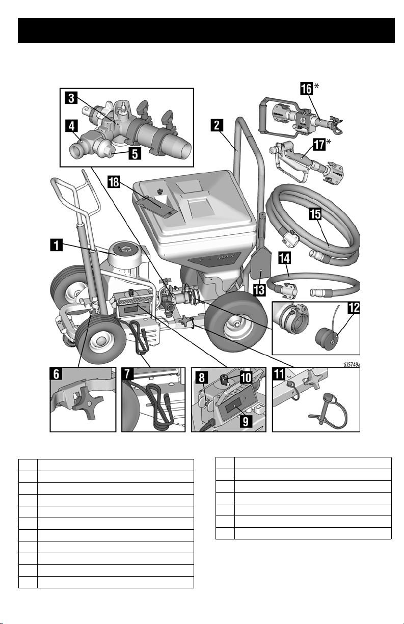
Component Identification 506
1 Pump Module
2 Hopper Frame
3Pump
4 Pump Outlet
5 Pressure Relief Valve
6 Module Securing Clamp
7 Power Cord
8 ON/OFF Switch
9 Display
10 Pressure Control Knob
11 Locking Pin
3A6748B 11
12 Hopper Plug
13 Scraper Tool
14 Whip Hose
15 Material Hose
16 T-Max Applicator
17 Inline Applicator
18 Tool Box
NOTE: All hoses sent with the unit are for
water-based material application only.
* See page14 for all applicators.
Page 12
Component Identification 657
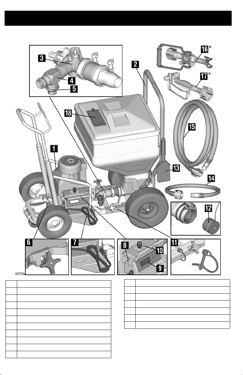
Component Identification 657
1 Pump Module
2 Hopper Frame
3Pump
4 Pump Outlet
5 Pressure Relief Valve
6 Module Securing Clamp
7 Power Cord
8 ON/OFF Switch
9 Display
10 Pressure Control Knob
11 Locking Pins
12 3A6748B
12 Hopper Plug
13 Scraper Tool
14 Whip Hose
15 Material Hose
16 T-Max Applicator
17 Inline Gun
18 Tool Box
NOTE: All hoses sent with the unit are for
water-based material application only.
* See page14 for all applicators.
Page 13
Component Identification 6912
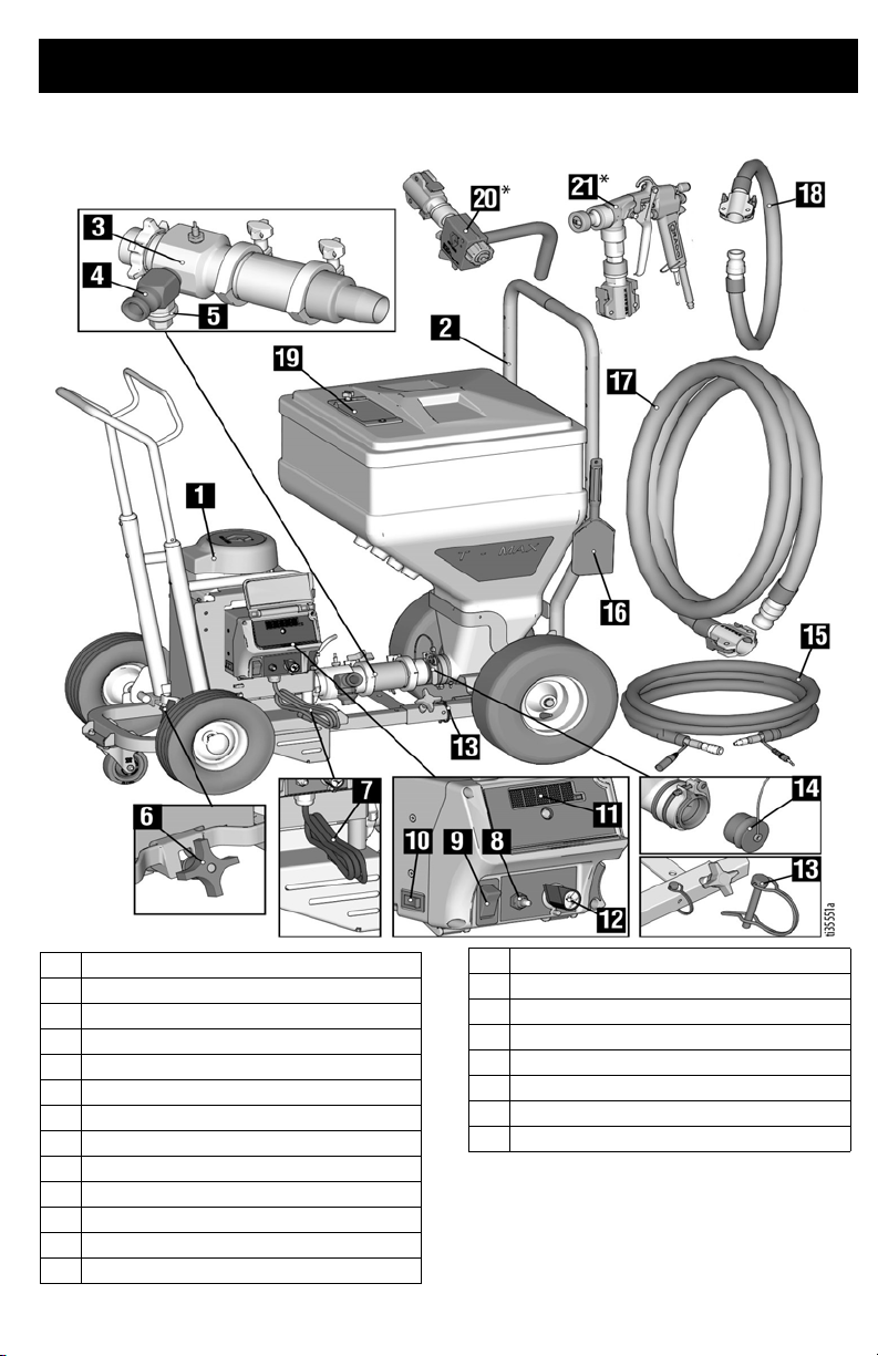
Component Identification 6912
1 Pump Module
2 Hopper Frame
3Pump
4 Pump Outlet
5 Pressure Relief Valve
6 Module Securing Clamp
7 Power Cord
8 Pump Mode Switch
9 ON/OFF Switch
10 Amp Switch
11 Display
12 Pressure Control Knob
13 Locking Pins
3A6748B 13
14 Hopper Plug
15 Signal / Air Hose
16 Scraper Tool
17 Material Hose
18 Whip Hose
19 Tool Box
20 Free Flow Applicator
21 STX Spray Gun
NOTE: All hoses sent with the unit are for
water-based material application only.
* See page14 for all applicators.
Page 14
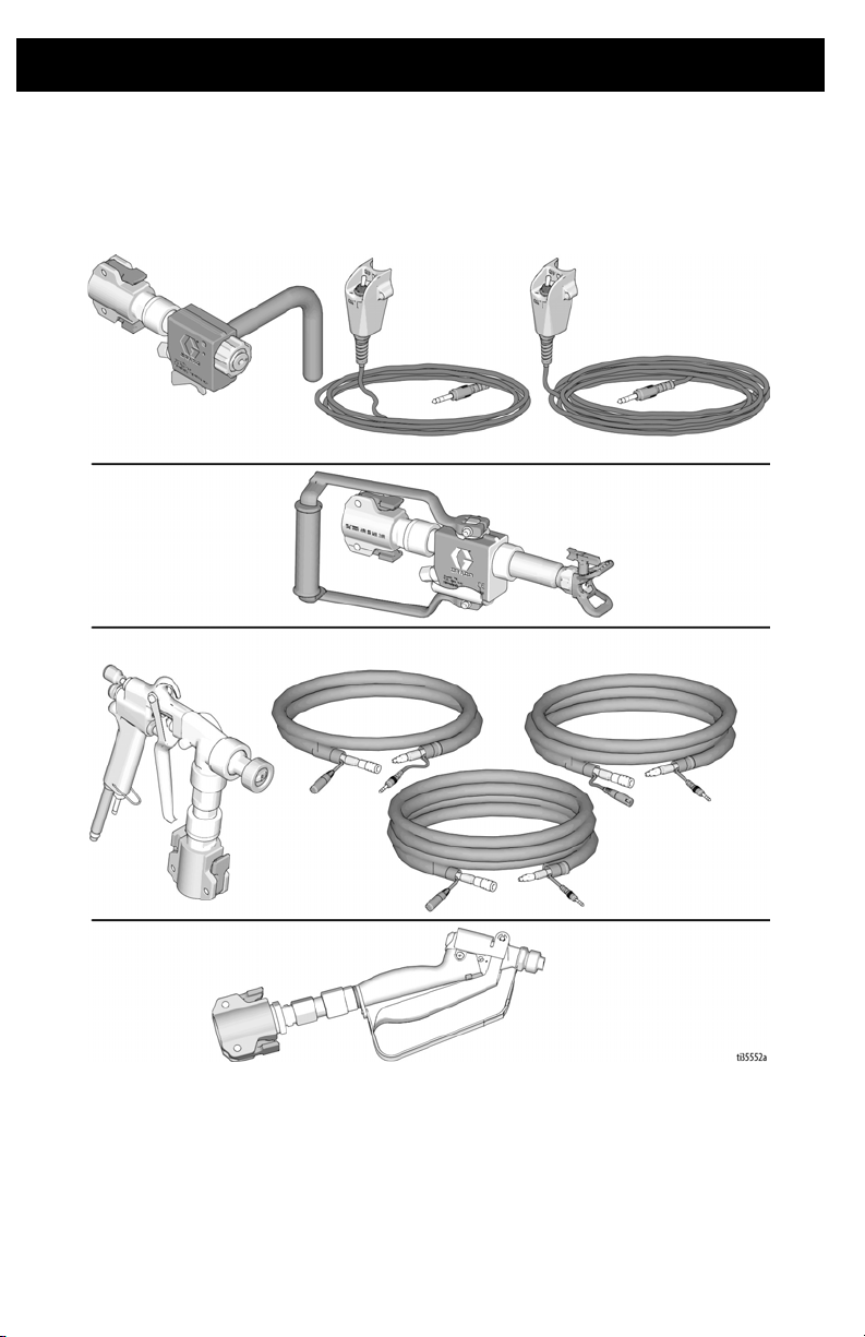
Component Identification
Free Flow
Applicator (17Z128)
T-Max Applicator
(17Z054)
STX Spray Gun
(17Y910)
18m Remote
Switch (17Z157)
30m Remote
Switch (17Z158)
13m Signal/Air
Hose (17Z144)
18m Signal/Air
Hose (17Z148)
33m Signal/Air
Hose (17Z151)
Inline Applicator
(17Y907)
Component Identification
14 3A6748B
Page 15
Pump Control Settings
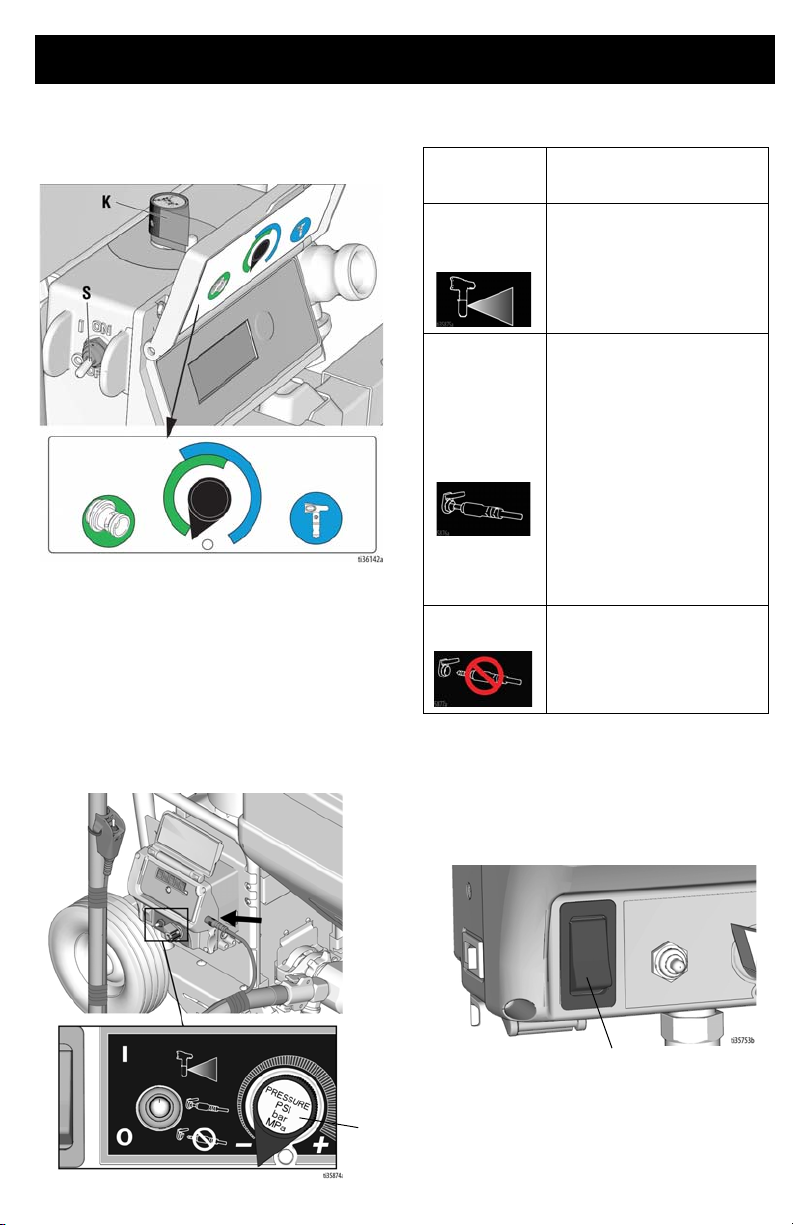
K
S
Pump Control Settings
T-Max 506/657
Flow Mode (first half of Pressure Control
Knob):
The motor will run continuously at the
speed determined by the Pressure Control
Knob (K). 0-100%
Pressure Mode (second half of Pressure
Control Knob):
pressure determined by the Pressure Control
Knob (K).
The motor will run to meet the
Pump Control
Setting Description
Pressure
Mode
Flow Mode
with Remote
Control
Flow Mode
The motor will run to meet the
pressure determined by the
Pressure Control Knob (K).
The “Flow Mode with Remote
Control” setting allows the
user to control ON/OFF
functionality of the pump
through the remote toggle
switch or the STX Spray
Gun. When the remote toggle
switch or the STX Spray Gun
is installed and the pump
control settings are set to
“Flow Mode with Remote
Control”, they can be used to
turn the pump ON and OFF.
The motor will run
continuously at the speed
determined by the Pressure
Control Knob (K). 0-100%
T-Max 6912
Operation
The motor power switch (S) must be
ON for the sprayer to pump material.
3A6748B 15
Page 16
Preparation
Preparation
Grounding
The equipment must be grounded to
reduce the risk of static sparking and
electric shock. An electric or static spark
can cause fumes to ignite or explode. An
improper ground can cause electric shock.
A good ground provides an escape wire for
the electric current.
This product is equipped with a cord having
a grounding wire with an appropriate
grounding plug. The plug must be plugged
into an outlet that is properly installed and
grounded in accordance with all local codes
and ordinances.
Do not modify the plug provided; if it does not
fit the outlet, have the proper outlet installed
by a qualified electrician.
Solvent-Based Materials
NOTE: All hoses sent with the unit are for
water-based material application only.
Solvent compatible hoses and applicators
must be used.
Flush the Equipment
• Flush with a fluid that is compatible with
the fluid being dispensed and the
equipment wetted parts.
• Flush at the lowest pressure possible.
Check connectors for leaks and tighten
as necessary.
1. Follow Pressure Relief Procedure,
page 19.
2. Set pump to lowest possible fluid
pressure, and start pump.
3. Hold a metal part of the gun firmly to a
grounded metal pail. Trigger the gun
until clean solvent dispenses.
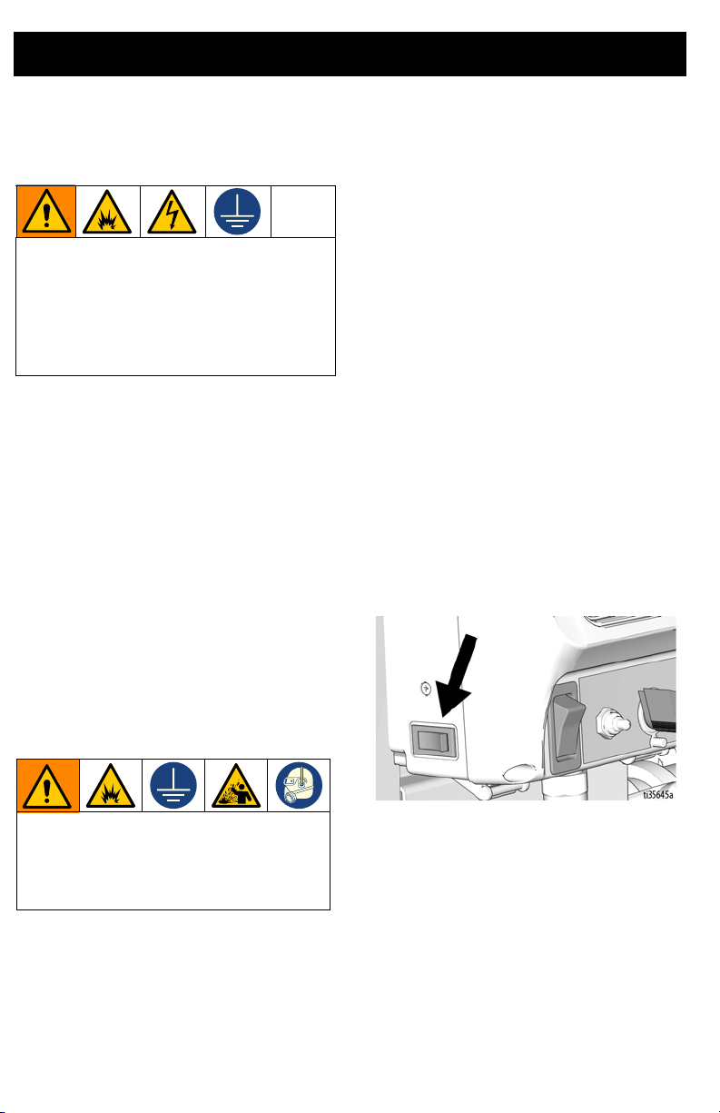
Amp Switch
Select 15A or 20A depending on your circuit
rating. 110V units require 100-120 VAC,
50/60 Hz, 15 – 20A, 1 phase
Select 10A or 16A depending on your circuit
rating. 230V units require 220-240 VAC,
50/60 Hz, 10 – 16A, 1 phase
To avoid fire and explosion, always
ground equipment and waste container.
To avoid static sparking and injury from
splashing, always flush at the lowest
possible pressure.
Flush before changing materials, before
•
fluid can dry or cure in the equipment, at
the end of the day, before storing, and
before repairing equipment.
16 3A6748B
Page 17
Preparation
ti2496c
40 lb.
TEXTURE MIX
5 GAL
PREMIX
5
GAL
ti2493b
Extension Cords
Use an extension cord with an undamaged
ground contact. If an extension cord is
necessary, use a 3-wire, 12 AWG (2.5 mm2)
minimum.
NOTE: Lighter gauge or longer extension
cords may reduce sprayer performance.
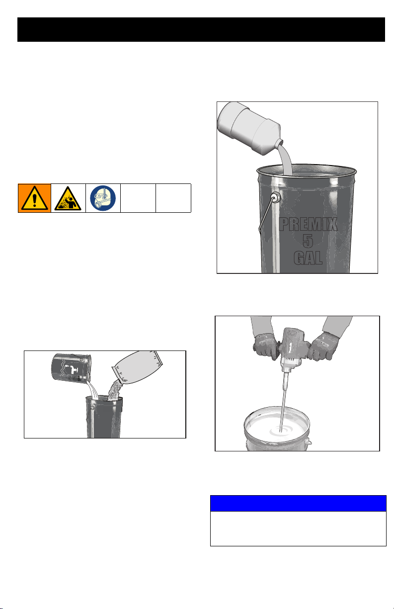
Mixing Material
NOTE: Correct material mixture is essential.
The pump and spray gun will not operate if
the mixture is too thick. Use water-based
materials only.
1. Mix the material and water in a
separate container.
Dry Mix
Carefully mix texture material and water
according to manufacturer instructions
on bag.
Premix
Slowly add water to a 5 gallon (18.9 liter)
bucket of premix.
2. Agitate to mix with mixing paddle, to a
smooth, lump-free consistency.
3. Make certain all dry powder clumps are
mixed throughly before pouring mixture
into the sprayer hopper.
NOTICE
Failure to make certain that all dry powder
is throughly mixed may cause tip or pump
clogging.
3A6748B 17
ti30766a
Page 18
Preparation
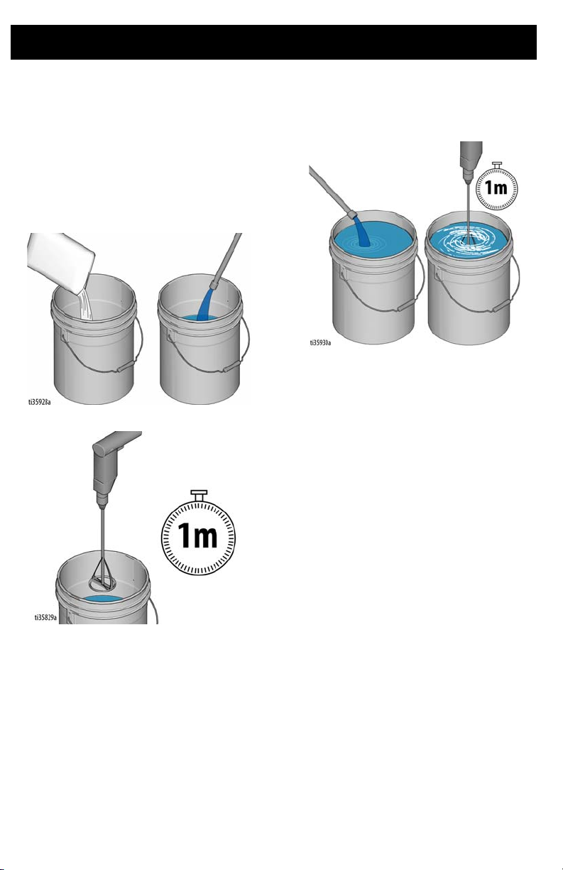
Hose Lubrication Mixing Instructions
Hose lubrication (17Z224) is used to lube the
pump and hose passages to reduce the risk
of packout when priming aggregate material.
NOTE: If using other hose lubricants, follow
manufacturer’s mixing instructions.
1. Empty one bag of hose lubricant into
five-gallon bucket and half fill with water.
2. Stir for one minute.
3. Fill remainder of bucket with water. Stir
for one minute.
4. Let mix stand for at least five minutes or
until a slick-like texture develops.
18 3A6748B
Page 19
Pressure Relief Procedure
Preparation
Follow the Pressure Relief
Procedure whenever you see this
symbol.
This equipment stays pressurized until
pressure is manually relieved. To help
prevent serious injury from pressurized
fluid, such as skin injection, splashing fluid
and moving parts, follow the Pressure
Relief Procedure when you stop spraying
and before cleaning, checking, or
servicing the equipment.
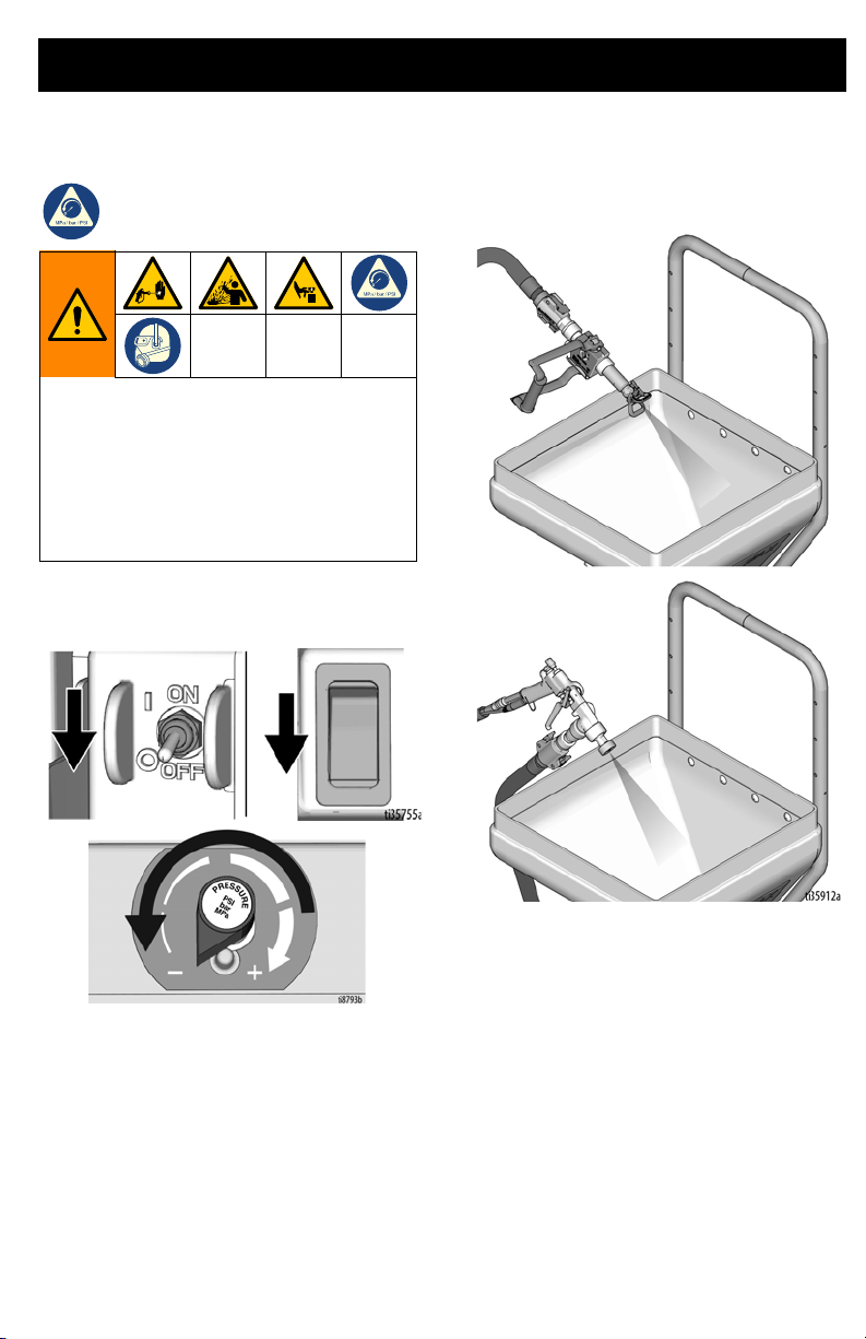
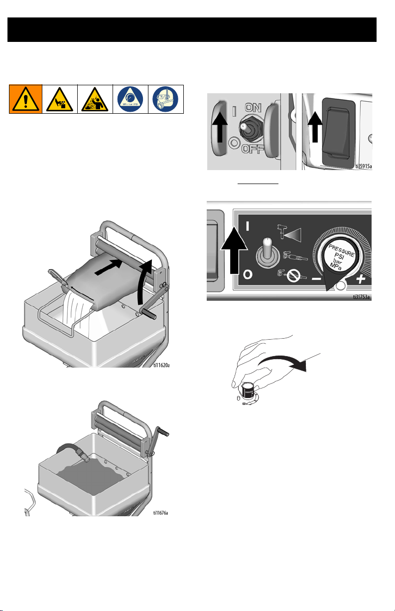
1. Turn ON/OFF Switch to OFF and turn
Pressure Control Knob fully
counterclockwise to OFF.
2. Point applicator into hopper. Turn
applicator ON.
3A6748B 19
Page 20
Preparation
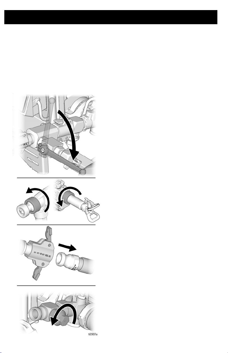
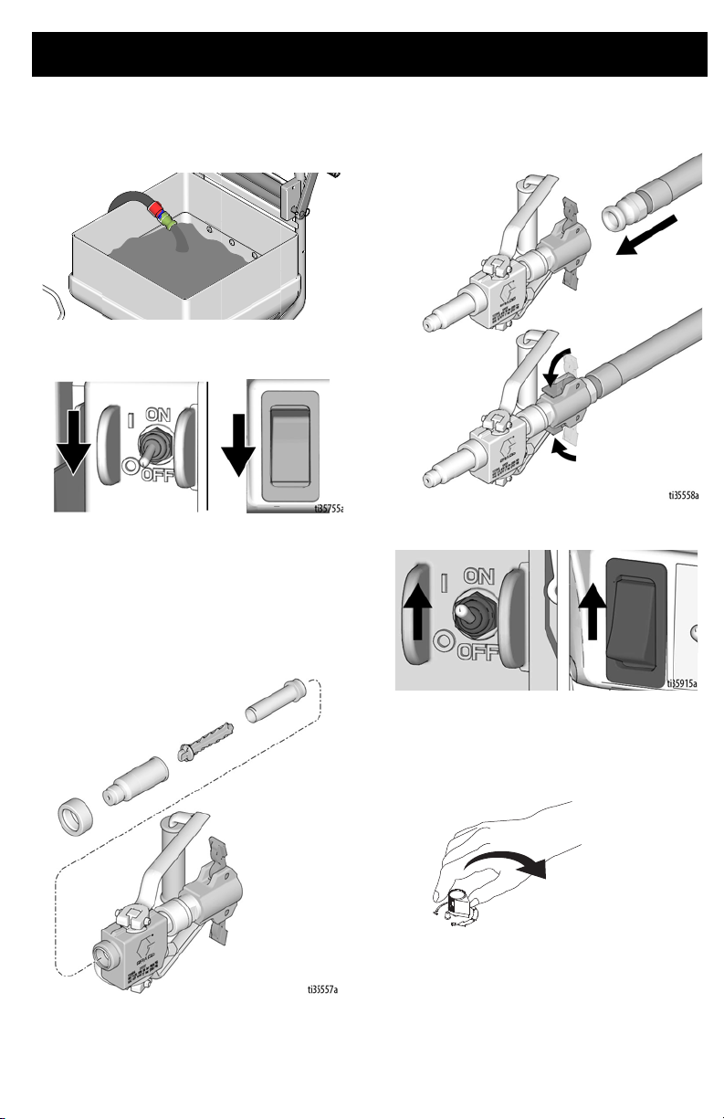
3. If you suspect the spray tip or hose is
clogged or that pressure has not been
fully relieved:
a. If installed, turn prime valve down to
prime position.
b. VERY SLOWLY loosen the
retaining ring, hose end coupling, or
pressure relief valve to relieve
pressure gradually.
c. Loosen the retaining nut or the
coupling completely.
d. Clear the obstruction in the hose or
tip.
NOTE: If pressure relief valve was used to
relieve pressure, be sure to disassemble and
clean thoroughly.
20 3A6748B
Page 21
Setup
When unpacking sprayer for the first time or
after long term storage perform setup
procedure. When first setup is performed
remove shipping plug from fluid outlet.
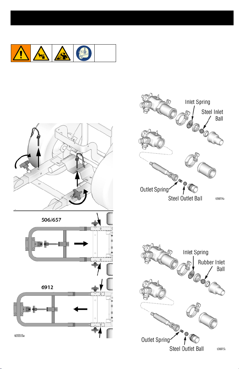
1. Loosen knobs on hopper frame and pull
out pins. Adjust hopper frame to fit the
506/657 (shortest frame position) or the
6912 (longest frame position).
Setup
Depending on materials being sprayed with
the T-Max 6912, different pump setups might
be desired. For disassembly instructions, see
Pump Repair, page 60.
a. Smooth materials: Use steel inlet
ball with spring and steel outlet ball
with spring. This is how the unit is
shipped.
b. Some aggregates: To help prevent
packout, use a rubber inlet ball with
spring and a steel outlet ball with
spring. NOTE: Sometimes it is
necessary to remove spring from
outlet if packout occurs. See Part C.
3A6748B 21
Page 22
Setup
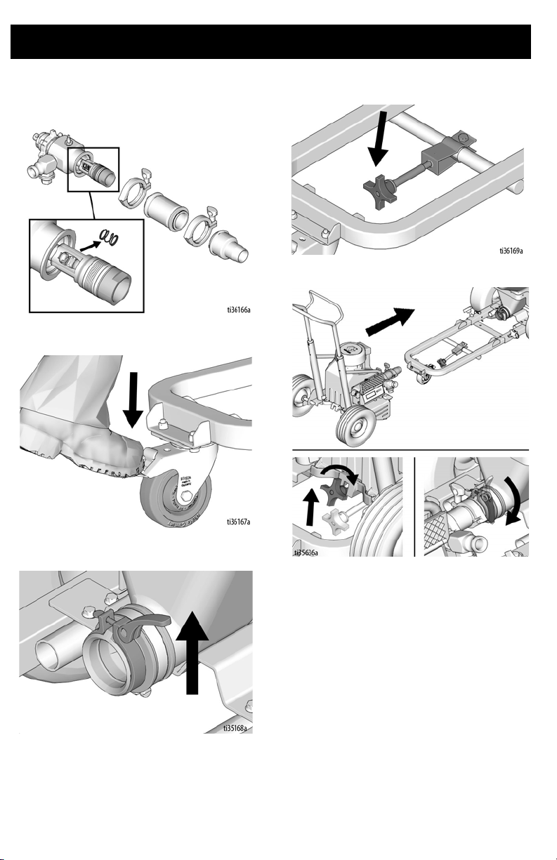
c. To remove outlet spring, remove
pump inlet and pump cylinder. Then
remove spring from the piston.
2. Lock front caster.
4. Move module securing clamp down.
5. Connect pump module to hopper frame.
3. Release hopper clamp.
22 3A6748B
Page 23

Setup
6. If hopper and pump do not align, loosen
four nuts on back of hopper. Make sure
hopper and pump are aligned and then
tighten four nuts.
7. Turn ON/OFF Switch to OFF. Connect
power cord.
8. Remove pump plug. Connect material
hose to pump outlet.
3A6748B 23
Page 24
Start Up - Airless
Start Up - Airless
Perform the start up procedure each time the
sprayer is started for the first time after it has
been cleaned or stored.
1. Perform Pressure Relief Procedure,
page 19.
2. Fill material hopper with pre-mixed
texture material. Bag roller sold
separately.
b. Turn ON/OFF Switch to ON.
c. 6912 only
Switch in up position.
d. Turn Pressure Control Knob
clockwise 1/4 turn.
: Place Pump Mode
3. Prime pump.
a. Place material hose in hopper.
24 3A6748B
Page 25
Start Up - Airless
ti11697a
ti8794a
e. Once a steady stream flows from
the material hose, run for an
additional 30 seconds.
f. Turn ON/OFF Switch to OFF.
4. Install filter or air passage plug and tip
extension. Material consistency and tip
size will determine which filter size to
use. In certain instances, air passage
plug with no screen is needed with large
tips to successfully spray materials with
sand or rock.
5. Connect applicator to material hose.
6. Turn ON/OFF Switch to ON.
7. Turn applicator ON. Turn Pressure
Control Knob clockwise until desired
material delivery rate is achieved. Run
for 15 seconds.
3A6748B 25
Page 26

Start Up - Airless
ti29242a
Spray Tip Installation
To avoid serious injury from skin injection
do not put your hand in front of the spray tip
when installing or removing the spray tip
and tip guard.
1. Perform Pressure Relief Procedure,
page 19.
2. Verify spray tip and tip guard parts are
assembled in the order shown.
c. Assemble retaining ring on tip guard
adapter then assemble tip guard.
3. Turn the arrow shaped handle on the
spray tip forward to the spray position.
a. Use spray tip to align gasket and
seal in the tip guard.
4. Screw spray tip and tip guard assembly
onto the gun and tighten.
b. Spray tip must be pushed all the
way into the tip guard. Turn spray tip
to push down.
26 3A6748B
Page 27

Start Up - Airless
ti11714a
ti11794a
ti11715a
ti11793a
Clear Spray Tip Clog
To avoid tip clogs:
• When the applicator is not in use for
extended periods of time, keep the tip
“wet” and perform Pressure Relief
Procedure, page 19.
• Keep spray tip clean and free of material.
1. Rotate spray tip to unclog position. Aim
applicator at floor and turn applicator
ON. When clog clears, turn applicator
OFF.
UNCLOG
2. Rotate spray tip back to spray position.
Turn applicator ON. Spray test pattern.
SPRAY
NOTE: When spraying, if the applicator is not
used for a significant period of time be sure to
clean the sprayer, or keep the gun “wet” by
placing in water or wrapping with a wet cloth.
This reduces the potential of the material
drying in the gun causing pack-out of the gun.
3A6748B 27
Page 28

Start Up - Air Assist
Start Up - Air Assist
Perform the start up procedure each time the
sprayer is started for the first time after it has
been cleaned or stored.
1. Perform Pressure Relief Procedure,
page 19.
2. To help prevent packout, fill material
hopper with hose lubrication. See Hose
Lubrication Mixing Instructions, page
18, then follow prime instructions. Pump
all hose lube through hose back into a
bucket then continue with the material
prime.
If spraying large aggregates, use rubber inlet
ball with spring and steel outlet ball with
spring.
To prime without outlet spring, remove hose
and pour water into the outlet. Place unit in
“flow mode” and turn Pressure Control Knob
clockwise until material comes out of the
pump outlet. Turn pressure control
counterclockwise until flow stops, then
connect material hose. If applicable, connect
a prime valve to the outlet, then connect
material hose. Open prime valve and slowly
turn the pressure control knob clockwise until
material comes out the prime valve.
Close prime valve and allow the hose to fill
(prime valve sold separately).
3. Fill hopper with mixed texture material.
NOTE: While priming material, allow residual
hose lube to flow into a bucket until material
starts to comes out.
NOTE: If having packout issues in the pump,
remove the outlet spring and run without it.
28 3A6748B
Page 29

Start Up - Air Assist
4. Prime pump.
a. Place material hose in hopper.
b. Turn ON/OFF Switch to ON.
c. Place Pump Mode Switch in down
position. Turn Pressure Control
Knob clockwise 1/4 turn.
d. Once a steady stream flows from
the material hose, run for an
additional 30 seconds.
ti11697a
e. Turn ON/OFF Switch to OFF.
3A6748B 29
Page 30

Start Up - Air Assist STX Gun
Start Up - Air Assist STX Gun
1. Turn air needle valve to low setting.
Connect applicator to material hose.
Connect signal wire connector to gun
handle, then the air hose.
2. Place Pump Mode Switch in center
position for remote pump control.
3. Hold applicator over material hopper and
turn applicator ON.
4. Turn Pressure Control Knob clockwise
until desired material delivery rate is
achieved. Run 15 seconds.
30 3A6748B
Page 31

Start Up - Air Assist STX Gun
5. When done spraying, release trigger.
The fluid passage will stay open,
relieving pressure.
6. When pressure is relieved, press trigger
stop button to close fluid passage.
7. Spray test pattern. Aim applicator at
floor. Turn air valve ON. Turn applicator
ON and move application to spray
surface.
8. Adjust air needle valve and/or select
alternative nozzle size (4 - 12mm) for
desired finish.
9. If a fan pattern is desired, remove
retaining ring and add adapter housing,
disk, and retaining nut to the assembly.
10. Select alternative disk (W4 - WXL) for
desired finish.
3A6748B 31
Page 32

Operation
ti11848a
Operation
The system has thermal overload
protection that will automatically shut
down the sysem if it overheats. To reduce
the risk of bodily injury due to the system
restarting unexpectedly, always turn the
ON/OFF switch to OFF.
An external air compressor may be
connected to the applicator air line fitting.
This may be useful for the application of
decorative or hard-to-spray materials.
Overpressurizing the system may cause
component rupture and result in serious
injury. To reduce risk of overpressurizing
system:
• Do not use a compressor with an
output pressure greater than 125 psi
(0.86 MPa, 8.6 bar).
The system comes with the following hoses:
T-Max 506:
• Fluid Hose: 5 m of 25 mm ID & 3 m
of 19 mm ID
T-Max 657:
• Fluid Hose: 10 m of 25 mm ID & 3 m
of 19 mm ID
T-Max 6912:
• Fluid Hose: 5m, 10m, 15m, 30m of
25mm ID & 3m of 19mm ID
• Air Hose: If applicable, 18m or 33m
Hose Usage
Always attach 25 mm ID hose to pump outlet.
Other hoses may then be added up to the
maximum fluid hose lengths:
• Use shortest fluid hose length required
for the spray application (25 mm x 5 m)
minimum.
• Unnecessary hose length decreases
sprayer performance.
• Maximum fluid hose lengths:
T-Max 506:
• 15 m of 25 mm ID or 10 m of 25 mm
ID + 3 m of 19 mm ID
T-Max 657:
• 30 m of 25 mm ID or 25 m of 25 mm
ID + 3 m of 19 mm ID
NOTE:
T-Max 6912:
• 30 m of 25 mm ID + 3m of 19mm ID
NOTE: Use only one 3 m of 19 mm ID. Do not
exceed 1000 psi. Temperature usage range
0°F - 180°F. All hoses sent with the unit are
for water-based material application only.
32 3A6748B
Page 33

Cleanup
ti11732a
ti11731a
Cleanup
Storage less than 24 hours
1. Perform Pressure Relief Procedure,
page 19.
2. Remove applicator. Keep applicator
“wet” by placing in water or wrapping
with a wet cloth.
3. Remove hose and couple ends together.
4. Clean hopper sides to material level.
Cover material in hopper with hopper
cover.
5. Disconnect pump from hopper.
3A6748B 33
Page 34

Cleanup
ti11711a
ti11850a
6. Install hopper plug.
7. Install cap on pump inlet.
8. Install pump cap (sold separately) on
pump outlet.
Storage more than 24 hours
1. Perform Pressure Relief Procedure,
page 19.
2. Shut air OFF if spraying with air. Remove
applicator from material hose. Clean
applicator.
3. Turn Pressure Control Knob clockwise
and pump unused texture from material
hopper and hose.
34 3A6748B
Page 35

Cleanup
4. Scrape remaining texture in hopper into
pump to be pumped from sprayer.
5. Rotate pump control to shut pump OFF.
7. Insert two wet cleaning balls into pump
outlet. Connect material hose to pump
outlet.
8. Fill material hopper with water and clean
sides.
9. Rotate Pressure Control Knob clockwise
to start pump.
6. Disconnect material hose from pump
outlet.
3A6748B 35
Page 36

Cleanup
10. Run pump until cleaning balls exit
material hose. Hold material hose
securely while passing balls through it.
Pressure can build up and make hose
jump. Save cleaning balls.
11. Rotate Pressure Control Knob to shut
pump OFF.
12. Connect applicator to material hose.
13. Turn Pressure Control Knob clockwise
to start pump.
14. Run pump until clean water flows from
applicator. Continue until hopper is
empty.
15. Add additional water and repeat steps 13
- 14, if necessary.
NOTE: After flushing with water, flush again
with Pump Armor to leave a protective
coating to prevent freezing and corrosion.
36 3A6748B
Page 37

Cleanup
16. Rotate Pressure Control Knob to shut
pump off.
17. Disconnect pump from hopper.
19. Clean applicators, spray tips and guard
with brush.
18. Flush hopper with water. Clean and
install drain plug.
3A6748B 37
Page 38

Cleanup
ti11811a
ti11847a
20. Clean hardened material from applicator
nozzles with air nozzle cleaner.
NOTICE
Do not use air nozzle cleaner to clean
applicator check valve and spray tip. Doing
so will damage both items.
38 3A6748B
Page 39

Troubleshooting
Troubleshooting
1. Follow Pressure Relief Procedure,
page 19, before checking or repairing.
2. Check all possible problems and causes
before disassembling unit.
Motor Will Not Operate
Problem Cause Solution
Basic Fluid Pressure Problems Pressure control knob setting.
Basic Mechanical Problems Frozen or hardened paint. Thaw sprayer if water or
Motor will not run if at minimum
setting (fully counterclockwise).
Spray tip or fluid filter may be
clogged.
Pump mode switch is not in the
proper position (6912).
Builds pressure but material will not
come out.
Displacement pump connecting rod
pin. Pin must be completely pushed
into connecting rod and retaining
spring must be firmly in groove of
pump pin.
Motor. With machine unplugged,
remove drive housing assembly.
Try to rotate fan by hand.
Slowly increase pressure setting to
see if motor starts.
Relieve pressure and clear clog or
clean filter; refer to separate gun or
tip instruction manual.
Place the pump mode switch in
proper position for application.
Up: Pressure Mode
Middle: Remote Control
Down: Flow Mode
Perform Pressure Relief
Procedure, page 19. Check
applicator, hose, and pump for
packout. May need to remove outlet
spring if packout in pump is
reoccuring.
water-based paint has frozen in
sprayer. Place sprayer in warm area
to thaw. Do not start sprayer until
thawed completely. If paint
hardened (dried) in spr ayer, replace
pump packing. See Pump Repair,
page 58.
Push pin into place and secure with
spring retainer.
Replace motor if fan won't turn.
3A6748B 39
Page 40

Troubleshooting
Problem Cause Solution
Basic Electrical Problems Motor control board. Board shuts
Motor is Hot and Runs Intermittently
down and displays error code.
Electrical supply. Meter must read:
210-255 Vac for 220-240 Vac
models;
85-130 Vac for 100-120 Vac
models.
Extension cord. Check extension
cord continuity with volt meter.
Sprayer power supply cord. Inspect
for damage such as broken
insulation or wires.
Check that motor leads are securely
fastened and properly mated.
ON/OFF Switch. Connect volt mete r
between L1 and L2 terminal on
ON/OFF switch. Plug in sprayer and
turn ON. Meter must read:
210-255 Vac for 220-240V models
85-130 Vac for 100-120V models.
Check all terminals for damage or
loose fit.
See Control Board Diagnostics,
page 43.
Reset building circuit breaker;
replace building fuse. Try another
outlet.
Replace extension cord.
Replace power supply cord.
Replace loose terminals; crimp to
leads. Be sure terminals are firmly
connected. Clean circuit board
terminals. Securely reconnect
leads.
Replace ON/OFF switch.
Replace damaged terminals and
reconnect securely.
Problem Cause Solution
Motor is hot and runs intermittently. Determine if sprayer was operated
at high pressure with small tips,
which causes low motor RPM and
excessive heat build up
Be sure ambient temperature where
sprayer is located is no more than
90°F and sprayer is not located in
direct sun
Decrease pressure setting or
increase tip size.
Move sprayer to shaded, cooler
area if possible.
40 3A6748B
Page 41

Troubleshooting
Low or Fluctuating Output
Problem Cause Solution
Low Output Worn spray tip. Follow Pressure Relief Procedure
Verify pump does not continue to
stroke when applicator is turned off.
Filter clogged (If optional filter is
installed).
Material hose length. Longer hose
length reduces sprayer
performance.
Pump hopper adapter connections. Tighten any loose connections.
Electrical supply with volt meter.
Meter must read:
210-255 Vac for 220-240 Vac
models;
85-130 Vac for 100-120 Vac
models. Low voltages reduce
sprayer performance.
Extension cord size and length;
must be at least 2.05 mm2 (12 awg)
wire and no longer than 90 m (295
ft). Longer cord lengths reduce
sprayer performance.
Leads from motor to pressure
control circuit board for damaged or
loose wires or connectors. Inspect
wiring insulation and terminals for
signs of overheating.
Low stall pressure. Turn pressure control knob fully
Fluctuating Output Material supply. Refill hopper and reprime pump.
Loose fittings. Tighten; use thread sealant or
Intake valve ball and piston ball are
not seating properly.
Leaking around throat packing nut
which may indicate worn or
damaged packings.
Pump rod damage. Repair pump.
3A6748B 41
Warning, then replace tip. See your
separate gun or tip manual.
Service pump. Check piston and
intake valves for wear or
obstructions.
Relieve pressure. Check and clean
filter.
Replace with hose length less than
specified maximum.
Replace pump hopper adapter if
cracked or punctured.
Reset building circuit breaker;
replace building fuse. Repair
electrical outlet or try another outlet.
Replace with a correct, grounded
extension cord.
Be sure male terminal blades are
centered and firmly connected to
female terminals. Replace any
loose terminal or damaged wiring.
Securely reconnect terminals.
clockwise. Make sure pressure
control knob is properly installed to
allow full clockwise position. Try a
new transducer. Check pump
control mode. If used in middle
position, the pump is limited to 600
psi.
sealing tape on threads if
necessary.
Remove intake and piston valves
and clean. Check balls and seats for
nicks or obstructions; replace if
necessary, page 58. Clean hopper
before using to remove particles
that could clog pump. Switch to a
rubber inlet ball (6912).
Replace packing, page 58. Also
check piston valve seat for
hardened paint or nicks and replace
if necessary.
Page 42

Troubleshooting
Problem Cause Solution
Motor runs but pump does not
stroke
Electrical Short
NOTICE
A short in any part of the motor power circuit will
cause the control circuit to inhibit sprayer
operation. Correctly diagnose and repair all shorts
before checking and replacing control board.
Problem Cause Solution
Building circuit breaker opens as
soon as sprayer switch is turned
on.
Building circuit breaker opens as
soon as sprayer is plugged into
outlet and sprayer is NOT turned
on.
Sprayer quits after sprayer
operates for 5 to 10 minutes.
Pump pin damaged or missing. Replace pump pin if missing. Be
Connecting rod assembly is
damage.
Gears or drive housing. Inspect drive housing assembly and
All electrical wiring for damaged
insulation, and all terminals for
loose fit or damage. Also wires
between pressure control and
motor.
Motor armature for shorts. Inspect
windings for burns
Motor control board by performing
motor control board diagnostics. If
diagnostics indicate, substitute
with a good board.
Basic Electrical Problems on
page 41.
For damaged or pinched wires in
pressure
control.
Basic Electrical Problems. Perform necessary procedures.
Electrical supply with volt meter.
Meter must read:
210-255 Vac for 220-240 Vac
models;
85-130 Vac for 100-120 Vac
models.
sure retainer spring is fully in groove
all around connecting rod.
Replace connecting rod assembly.
gears for damage and replace if
necessary.
Repair or replace any damaged
wiring or terminals. Securely
reconnect all wires.
Replace motor.
Replace with a new motor control
board.
Perform necessary procedures.
Replace damaged parts.
If voltage is too high, do not
operate sprayer until corrected.
42 3A6748B
Page 43

Repair
Control Board Diagnostics
Repair
1. Perform Pressure Relief Procedure,
page 19.
NOTE: Do not allow sprayer to develop fluid
pressure without transducer installed. Leave
pump outlet open if test transducer is used.
Control
board status
Display
No Display Never blinks Spray stops. Power is not
psi/bar/MPa Once Sprayer is pressurized. Power is
E=02
CODE 02
E=03
CODE 03
E=04
CODE 04
E=05
CODE 05
E=06
CODE 06
LED Blinks
Two times
repeatedly
Three times
repeatedly
Four times
repeatedly
Five times
repeatedly
Six times
repeatedly
Spray Operation Indicates What to Do
applied. Sprayer must be
pressurized.
applied. (Pressure varies with tip
size and pressure control
setting.)
Sprayer may continue to run.
Power is applied.
Sprayer shuts down and LED
continues to blink three times
repeatedly
Sprayer does not operate. Control board is
Sprayer does not start or stops
and LED continues to blink five
times repeatedly. Power is
applied.
Sprayer stops and LED blinks six
times repeatedly. Power is
applied.
2. Observe display messages in the
following table.
3. Observe LED operation and reference
the following table.
Loss of power. Check power source. Perform
Normal operation. Do nothing.
Run away pressure.
Pressure greater
than 1500 psi (103
bar, 10.3 MPa) or
damaged pressure
transducer.
Pressure transducer
is faulty or missing.
detecting multiple
voltage surges.
Motor fault. Check for locked rotor,
Motor is too hot or
there is a fault in
motor thermal
device.
Pressure Relief Procedure,
page 19, before repair or
disassembly.
Replace motor control board
or pressure transducer.
Check transducer connection.
Open drain valve. Substitute
new transducer for transducer
in sprayer. If sprayer runs,
replace transducer.
Check voltage switch, ensure
it is in the right voltage setting
for the voltage being used. Set
Sprayer to OFF and
disconnect power to sprayer.
Locate a good voltage supply
to prevent damage to
electronics.
shorted wiring or
disconnected motor. Repair or
replace failed parts.
Allow sprayer to cool. If
sprayer runs correctly when
cool, check motor fan function
and air flow. Keep sprayer in
cool location. If sprayer does
not run when cool and
continues to blink six times,
replace motor.
3A6748B 43
Page 44

Repair
Control
board status
Display
CODE 08 Eight times
CODE 10 Ten times
CODE 12 Twelve times
CODE 15 Fifteen times
CODE 16 Sixteen times
CODE 17 Seventeen
- - - Power is applied. Pressure less than
LED Blinks
repeatedly
repeatedly
repeatedly
repeatedly
repeatedly
times
repeatedly
Spray Operation Indicates What to Do
Sprayer does not operate. Voltage supply to
Sprayer does not operate. Overheating control
Sprayer does not operate. Excessive current
Sprayer does not operate. Motor connection
Sprayer does not operate. Control is not
Sprayer does not operate. Wrong voltage
low.
board
protection enabled.
problem.
receiving a motor
position signal.
detected.
60 psi (4.1 bar, 41
MPa).
Set sprayer to OFF and
disconnect power to sprayer
remove other equipment that
uses the same circuit. Locate
a good voltage supply to avoid
damage to electronics.
Make sure motor air intake is
not blocked. Make sure fan
has not failed. Make sure
control board is properly
connected to back plate and
that conductive thermal paste
is used on power
components. Replace control
board. Replace motor.
Cycle power on and off.
Set sprayer to OFF and
disconnect power to sprayer.
Remove motor shroud.
Disconnect motor control and
inspect for damge at
connectors.
Turn power OFF. Disconnect
motor position sensor and
inspect for damage at
connectors. Reconnect
sensor. Turn power on. If
problem continues, replace
motor.
Check voltage switch, ensure
it is in the right voltage setting
for the voltage being used. Set
Sprayer to OFF and
disconnect power to sprayer.
Locate a good voltage supply
to prevent damage to
electronics.
Increase pressure if desired.
Drain valve may be open.
44 3A6748B
Page 45

Repair
ti11854a
Control Board Removal 506/657
1. Perform Pressure Relief Procedure,
page 19. Unplug power cord to
disconnect power.
2. Separate pump from hopper.
3. Remove four screws and motor cover.
4. Remove four screws and control cover.
Disconnect display from control board.
3A6748B 45
Page 46

Repair
ti11853a
ti11856a
5. Reference Wiring Diagram, page 81.
Remove screw. Disconnect ground, blue
and brown leads.
6. Remove power cord from control box.
7. Remove filter board screws.
8. Remove ON/OFF switch toggle boot.
9. Disconnect black lead from control
board to filter board.
10. Remove filter board from control box.
46 3A6748B
Page 47

Repair
ti11864a
409
ti11862a
A
B
E
D
C
ti11863a
ti11863a
ti11862a
A
B
E
D
C
ti11864a
11. Remove screw from bottom of control
box.
12. Disconnect motor (A), thermister (B),
potentiometer (C) and transducer (D)
connectors. Remove grommet (E).
Control Board Installation 506, 657
1. Install control board with four screws.
2. Connect motor (A), thermister (B),
potentiometer (C) and transducer (D)
connectors. Install grommet (E).
13. Remove four screws and control board.
3. Install screw through bottom of control
box.
3A6748B 47
Page 48

Repair
ti11856a
412
ti11853a
4. Install filter board in control box.
5. Connect black lead from control board to
filter board.
6. Install ON/OFF switch toggle boot.
7. Install filter board screw.
8. Install power cord (C) in control box.
9. Reference Wiring Diagram, page 81.
Connect ground, blue and brown leads.
Install screw.
48 3A6748B
Page 49

Repair
ti11854a
ti11737a
10. Connect display to control board. Install
control cover with four screws.
11. Install motor cover with four screws.
Control Board Removal 6912
1. Perform Pressure Relief Procedure,
page 19. Unplug power cord to
disconnect power.
2. Separate pump from hopper.
3A6748B 49
Page 50

Repair
3. Remove four screws and motor cover. 4. Remove four screws and open cover.
5. Remove two screws and remove filter
board and amp switch.
50 3A6748B
Page 51

Repair
6. Reference Wiring Diagrams, page 82.
Disconnect mode switch (yellow and
black), transducer, potentiometer, amp
switch, LED display filter board (black,
blue). Remove front cover.
7. Disconnect motor leads, thermal switch,
and motor hall/encoder sensor. Remove
grommet.
8. Remove two screws from back of control
box and remove box.
Control Board Installation 6912
1. Install control box with two screws.
3A6748B 51
Page 52

Repair
2. Connect motor leads, thermal switch,
and motor hall/encoder sensor. Install
grommet.
3. Reference Wiring Diagrams, page 82.
Connect mode switch (yellow and
black), transducer, potentiometer, amp
switch, LED display filter board (black,
blue).
4. Install filter board in control box with two
screws. Install amp switch.
5. Close cover and install four screws.
52 3A6748B
Page 53

6. Install motor cover using four screws. 7. Connect pump to hopper.
Repair
3A6748B 53
Page 54

Repair
ti11854a
506/657
6912
Pump Removal
1. Perform Pressure Relief Procedure,
page 19. Unplug power cord to
disconnect power.
2. Perform Storage more than 24 hours
procedure, page 34.
3. Separate pump from hopper.
4. Remove four screws and motor cover.
5. Remove four screws and control cover.
54 3A6748B
Page 55

Repair
ti11867a
ti11747a
6. Disconnect transducer from control
board. Remove transducer and strain
relief from control box.
7. Slowly rotate fan blade on motor until
connecting rod is at bottom of stroke.
9. Loosen retaining nut.
10. Unscrew pump from bearing housing.
8. Pry retaining spring up on connecting
rod toward motor. Push pump pin out
with a screwdriver.
3A6748B 55
Page 56

Repair
ti11879a
5
0
-
7
0
m
m
ti11747a
Pump Installation
1. Push piston rod out of pump 50 to 70 mm
(2 to 2.8 in.).
2. Screw retaining nut onto pump until it
stops. Screw pump into bearing housing
until pump stops. Unscrew pump until
pump outlet is 13° from horizontal,
but no more than one turn.
3. Tighten retaining nut.
If pump pin loosens, parts may break off
due to force of pumping action. Parts may
project through the air and result in serious
injury or property damage. Make sure
pump pin and retaining spring are properly
installed.
4. Push retaining spring up with a
screwdriver toward motor. Push in pump
pin. Push retaining spring down over
pump pin.
56 3A6748B
Page 57

Repair
ti11854b
506/657
6912
5. Install transducer and strain relief in
control box. Connect transducer to
control board.
6. Install control cover with four screws.
7. Install motor cover with four screws.
8. Connect pump module.
3A6748B 57
Page 58

Repair
Pump Repair 506/657
Disassembly
NOTE: It may be easier to leave the pump
connected to the connecting rod and bearing
housing if the only assembies to be cleaned
and inspected are the intake housing or
piston valve.
1. Perform Pressure Relief Procedure,
page 19. Unplug power cord to
disconnect power.
2. Refer to Pump Removal, page 54, to
remove pump.
3. Remove clamp and intake housing.
4. Remove clamp and pump cylinder.
5. Remove packing nut. Push piston rod
from outlet housing.
6. Place end of piston rod in vise and
remove piston valve (12). Remove
piston seal (16). Inspect all parts for
nicks and scratches. Replace worn or
damaged parts as they may result in
poor pump performance.
58 3A6748B
Page 59

Repair
A
ti11755a
Assembly
1. Place end of piston rod in vise. Install
new piston seal. Torque piston valve to
27 ft-lb (36,6 N·m).
2. Install packing nut. Hand tighten then tap
with screw driver. Push piston rod into
outlet housing. Extend piston rod 50 - 75
mm (A) out of outlet housing.
3A6748B 59
Page 60

Repair
ti11752a
3. Install clamp on pump cylinder. Torque
clamp to 100in-lb (11.3 Nm).
4. Install clamp on intake housing. Torque
clamp to 100in-lb (11.3 Nm).
Pump Repair 6912
Disassembly
NOTE: It may be easier to leave the pump
connected to the connecting rod and bearing
housing if the only assembies to be cleaned
and inspected are the intake housing or
piston valve.
1. Perform Pressure Relief Procedure,
page 19. Unplug power cord to
disconnect power.
2. Refer to Pump Removal, page 54, to
remove pump.
3. Remove clamp and intake housing.
5. Refer to Pump Installation, page 56, to
install pump.
4. Disassemble intake valve.
60 3A6748B
Page 61

5. Remove clamp and pump cylinder.
6. Remove packing nut. Push piston rod
from outlet housing. Remove throat
packings and glands from cylinder.
Discard throat packings and glands.
Repair
7. Place cage of piston rod in vise and
remove piston valve. Remove piston
seal. Remove packings and glands from
piston rod. Inspect all parts for nicks and
scratches. Replace worn or damaged
parts as they may result in poor pump
performance.
3A6748B 61
Page 62

Repair
Assembly
1. Place cage of piston rod in vise. Install
new piston seal. Torque piston valve to
90 ft-lb (122 N·m). Install piston wiper
(note orientation, page 63) and backup
washer on piston valve, threads are
good for four repackings. Use thread
sealant on piston valve threads after four
repackings. Stack male gland on piston
rod. Alternately stack light and dark
packings (note orientation, page 63) on
piston rod. Install female gland.
2. Install packing nut. Hand tighten then tap
with screw driver. Push piston rod into
outlet housing. Extend piston rod 50 - 75
mm (A) out of outlet housing.
62 3A6748B
Page 63

Repair
Cross-Section Reference / Pump Ball Identification 6912
3A6748B 63
Page 64

Repair
Motor Removal
1. Perform Pressure Relief Procedure,
page 19. Unplug power cord to
disconnect power.
2. Remove pump. See Pump Removal,
page 54.
3. Tip unit on back.
4. While supporting motor/drive housing,
remove two screws from base.
5. Remove four screws, washers and
bearing housing.
NOTE: Do not drop gear cluster when
removing drive housing. Gear cluster may
stay engaged in motor front end bell or drive
housing.
6. Remove three screws and drive
housing.
7. Remove screw and fan.
64 3A6748B
Page 65

Repair
Motor Installation
NOTICE
When installing motor, carefully align gears
to avoid damaging mating parts.
1. Install drive housing with three screws.
2. Install bearing housing with four screws
and washers. Torque to 25 - 30 ft-lbs
(33.9 - 40.67 N·m).
3. Install motor with two screws. Torque to
200 - 220 in-lbs (22.6 - 24.9 N·m).
4. Install fan with screw. Torque 11 - 13
in-lb (1.24 - 1.46 N·m).
5. Install pump. See Pump Installation,
page 56.
3A6748B 65
Page 66

Repair
Recycling and Disposal at End of Life
At the end of the product’s useful life,
dismantle and recycle it in a responsible
manner.
Preparation:
• Perform the Pressure Relief
Procedure.
• Drain and dispose of fluids according to
applicable regulations. Refer to the
material manufacturer’s Safety Data
Sheet.
Dismantle and recycle:
• Remove motors, circuit boards, LCDs
(liquid crystal displays), and other
electronic components. Recycle
according to applicable regulations.
• Do not dispose of electronic components
with household or commercial waste.
• Deliver remaining product to a recycling
facility.
66 3A6748B
Page 67

Notes
Notes
3A6748B 67
Page 68

Parts - Hopper Frame
b
a
Parts - Hopper Frame
68 3A6748B
Page 69

Parts List - Frame
Parts - Hopper Frame
Ref. Part
1 19A673 FRAME, hopper, Tmax 1
2 156306 WASHER, flat 2
3 116038 WASHER, wave spring 2
4 119509 WHEEL, pneumatic 2
5 120211 RING, retaining, e-ring 2
6 19A675 BRACKET, support,
7 129335 SCREW, hex, serrated,
8 102040 NUT, lock, hex 9
9 25E625 FRAME, mounting, power
10 17N602 CASTER, swivel 1
11 110963 SCREW, cap, hex hd 4
12 111040 NUT, lock , insert, nylock
13 15C797 BRACKET, swivel 1
14 101566 NUT, lock 1
15 100004 SCREW, cap, hex hd 1
16 104430 PIN, cotter 1
17 15C799 ROD, clamp 1
Description Qty
hopper
1/4-20 x 2.00
module
5/16
Ref. Part
18 19A674 BRACKET, guide, hopper 1
19 113796 SCREW, flanged, hex hd 4
20 HOPPER, material
20a 25E541 17 gallon 1
20b 25E542 25 gallon 1
21 404533 BOLT, carriage 4
1
22 112958 NUT, hex, flanged 3/8 -16 4
23 121313 PIN, locking, 1-4” 2
4
24 111145 KNOB, pronged 2
27 15D306 PLUG, adapter, hopper 1
30 234188 CLAMP, quick release 1
1
31 19A646 TOOL, scraper 1
32 130878 BOLT, hook, 1/4-20 x
34 15D561 COVER, tool tray 1
4
35 115814 WASHER, flat, sst 2
36 551787 SCREW, cap 1
37 19A714 KNOB, stuf, #10-32 x .44 1
38 120481 SLEEVE, oval 4
39 120483 CABLE 2.5
50 19A748 LABEL, brand, Tmax, left 1
51 19A749 LABEL, brand, Tmax, right 1
Description Qty
1-5/8 thd
1
3A6748B 69
Page 70

Parts - Power Module 506/657
PAGE 78
PAGES 74, 75
Parts - Power Module 506/657
70 3A6748B
Page 71

Parts - Power Module 506/657
Parts List - Power Module 506/657
Ref. Part
1 287234 HOUSING, drive, Tmax
287235 HOUSING, drive, Tmax
2 116192 WASHER, thrust 1
3 114672 WASHER, thrust 2
4 114699 WASHER, thrust 1
5 243951 GEAR, cobination 1
6 289570 MOTOR 1
7 15C753 SCREW, mach, hex
8 240724 HOUSING, bearing 1
9 287395 ROD, connecting 1
10 106115 WASHER, lock 4
11 114666 SCREW, cap, socket
12 19A690 BASE, drive module,
13 120981 SCREW, mach, hex
14 119778 SPRING, retaining 1
17 15F856 PIN, pump 1
18 19A585 GUIDE, power module 2
19 100023 WASHER, flat 4
20 112746 NUT, lock, nylon 4
21 19A669 FRAME, right, Tmax,
22 19A670 FRAME, left, Tmax,
23 107129 BOLT, round head 4
35 15D088 FAN, motor 1
36 115477 SCREW, mach, torx
Description Qty
506
657
wash hd
head
machined
washer hd
painted
painted
pan hd
Ref. Part
42 19A713 BUMPER, rubber 1
1
43 115483 NUT, lock 2
44 103374 SCREw, mach, rhd 2
45 106062 WHEEL, semi-
46 101242 RING, retaining 2
47 104811 CAP, hub 2
51 100016 WASHER, lock 2
52 110298 SCREW, cap, sch 2
91 15R741 SHIELD, Tmax, painted 1
3
92 118444 SCREW, mach, slot hex
93 15T629 SHIELD, pump rod 1
97 287489 HANDLE, assy, hi cart 1
98 109032 SCREW, mach, pnh 2
4
191 187437 LABEL, torque 1
1
193 19A814 LABEL, brand, Tmax
2
1
1
19A815 LABEL, brand, Tmax
194 15U014 LABEL, brand, Tmax
195 17P925 LABEL, A+ Service 1
196 15Y118 LABEL, made in USA 1
197 15H108 LABEL, safety, warning,
198 17Z485 LABEL, safety 1
16C681 LABEL, notice 1
199
Description Qty
pneumatic
wash hd
506
657
cap
pinch
Replacement safety labels, tags, and
cards are available at no cost.
1
2
6
1
1
1
1
3A6748B 71
Page 72

Parts - Power Module 6912
PAGE 80
PAGE 76
Parts - Power Module 6912
72 3A6748B
Page 73

Parts - Power Module 6912
Parts List - Power Module 6912
Ref. Part
1 24M008 HOUSING, drive 1
2 116192 WASHER, thrust 1
3 114672 WASHER, thrust 2
4 114699 WASHER, thrust 1
5 243951 GEAR, combination 1
6 25P037 KIT, repair, motor 1
7 15C753 SCREW, mach, hex
8 245795 HOUSING, bearing 1
9 287395 ROD, connecting 1
10 106115 WASHER, lock 4
11 114666 SCREW, cap, socket,
12 19A690 BASE, drive module 1
13 120981 SCREW, mach, hex
14 17Z347 SPRING, retaining 1
17 15F856 PIN, pump 1
18 19A585 GUIDE, power module 2
19 100023 WASHER, flat 4
20 112746 NUT, lock, nylon 4
21 19A671 FRAME, right, Tmax,
22 19A672 FRAME, left, Tmax,
23 107129 BOLT, round head 4
24 117791 SCREW, cap 2
35* 15D088 FAN, motor 1
36* 115U77 SCREW 1
42 19A713 BUMPER, rubber 2
Description Qty
wash hd
head
washer hd
painted
painted
Ref. Part
43 115483 NUT, lock 2
44 103374 SCREW, mach 2
45 106062 WHEEL, semi-
46 101242 RING, retaining 2
47 104811 CAP, hub 2
3
4
2
1
1
49 19A738 GROMMET 1
91 19A676 COVER, motor, Tmax,
92 118444 SCREW, mach, slot hex
93 19A666 SHIELD, assy w/
94 15T629 SHIELD, pump rod 1
95 19A715 BRACE, front 1
96 126687 SCREW, mach, pnh 4
97 287489 HANDLE, assy, hi cart 1
98 109032 SCREW, mach, pnh 4
191 187437 LABEL, torque 1
193 19A750 LABEL, 6912 brand 1
194 15U014 LABEL, cap brand 1
195 17P925 LABEL, A+ service 1
196 15Y118 LABEL, made in USA 1
15H108 LABEL, pinch 1
197
16G596 LABEL, safety 1
198
16C681 LABEL, notice 1
199
* Included in Motor Repair Kit 25P037
Description Qty
2
pneumatic
1
painted
10
wash hd
1
shroud, painted
Replacement safety labels, tags, and
cards are available at no cost.
3A6748B 73
Page 74

Parts - Pump 289555 (506)
Parts - Pump 289555 (506)
Parts List - Pump
Ref. Part Description Qty
1 15D117 TUBE, fiber, pump 1
2 107185 PACKING, o-ring 1
3 118597 PACKING, u-cup 1
4 15R739 HOUSING, outlet,
machining
5 118598 CLAMP, sanitary, 1.5 in. 2
6 15R740 CYLINDER, pump 1
7 248232 VALVE, piston 1
248530 KIT, repair, seal, piston,
includes 7, 13, 15, 16
8 248162 SPRING, Intake ball 1
9 193395 SEAT, carbide 1
10 107098 PACKING, o-ring 1
11 15R620 ROD, pump 1
12 15D112 NUT, packing 1
74 3A6748B
Ref. Part Description Qty
13 501095 SPRING, ball check 1
14 121588 O-RING 2
15 101822 BALL, bearing 1
16 15D116 SEAL, piston 1
1
17 15D115 GUIDE, ball 1
18 107167 BALL, sst 1
19 248769 HOUSING, intake 1
37 111457 O-RING 1
38 289672 TRANSDUCER 1
1
40 17Z238 OUTLET 1
41 17Y930 RELIEF, pressure 1
48 17Z345 PLUG 1
49 121429 O-RING 1
50 193031 NUT, retaining 1
51 248530 KIT, valve, piston
includes 7, 13, 15, 16
1
Page 75

Parts - Pump 289556 (657)
Parts - Pump 289556 (657)
Parts List - Pump
Ref. Part Description Qty
1 15D117 TUBE, fiber, pump 1
2 107185 PACKING, o-ring 1
3 118597 PACKING, u-cup 1
4 15R621 HOUSING, outlet,
machining
5 500984 CLAMP 2
6 15R619 CYLINDER, pump 1
7 248232 VALVE, piston 1
248530 KIT, repair, seal, piston,
includes 7, 13, 15, 16
8 248162 SPRING, Intake ball 1
9 193395 SEAT, carbide 1
10 107098 PACKING, o-ring 1
11 15R620 ROD, pump 1
12 15D112 NUT, packing
248529 KIT, repair, throat seal
includes 1, 2, 3, 12
3A6748B 75
Ref. Part Description Qty
13 501095 SPRING, ball check 1
14 121587 O-RING 2
15 101822 BALL, bearing 1
16 15D116 SEAL, piston 1
1
17 15D115 GUIDE, ball 1
18 107167 BALL, sst 1
19 289941 HOUSING, intake 1
37 111457 O-RING 1
38 289672 TRANSDUCER 1
1
40 17Z238 OUTLET 1
41 17Y930 RELIEF, pressure 1
48 17Z345 PLUG 1
49 121429 O-RING 1
50 193031 NUT, retaining 1
51 248530 KIT, valve, piston
1
includes 7, 13, 15, 16
1
Page 76

Parts - Pump 25E668 (6912)
Parts - Pump 25E668 (6912)
76 3A6748B
Page 77

Parts - Pump 25E668 (6912)
Parts List - Pump 25E668 (6912)
Ref. Part Description Qty
1 19A610 HOUSING, outlet,
machining
2† 187939 GLAND, male 1
3† 187071 PACKING, vee 3
4† 188560 PACKING 2
5† 187070 GLAND, female 1
6† 19A625 WIPER, fiber, pump rod 1
7 19A685 NUT, packing 1
8 25E669 ROD, pump 1
8a 19A686 ROD, pump 1
8b 19A689 HOUSING, piston pump 1
8c 19A691 BALL, stop 1
8d 130862 SPRING, compression 1
8e 107167 BALL, sst 1
8g† 188432 GLAND, packing, male 1
8h† 187072 PACKING 3
8j† 188561 PACKING, throat 2
8k† 188433 GLAND, packing, female 1
8m† 188558 SEAL, u-cup 1
8n† 188627 WASHER, back-up 1
8o 17Z242 VALVE, piston, assy 1
9 19A609 CYLINDER, pump 1
Ref. Part Description Qty
10† 130792 O-RING 2
11 620223 CLAMP 2
12 17Z241 HOUSING, intake ball 1
13 235962 SEAL, foot valve 1
14 19A692 GUIDE, ball, inlet 1
15 25E679 SPRING, intake, assy 1
16 102973 BALL, metallic 1
37 111457 O-RING 1
38 289672 KIT, includes 37 1
40 17Z238 OUTLET 1
41 17Y930 RELIEF, pressure 1
50 193394 NUT 1
17Z556 BALL, sst, inlet & outlet
17Z648 BALL, hard, white, inlet &
outlet
17Z640 BALL, hard, black, inlet &
outlet
17Z231 BALL, rubber, inlet
248515 BALL, cleaning
† included in Pump Repack Kit 17Z641
3A6748B 77
Page 78

Parts - Control Box 506/657
Parts - Control Box 506/657
78 3A6748B
Page 79

Parts - Control Box 506/657
Parts List - Control Box 506/657
Ref. Part Description Qty
1 277228 BOX, control 1
2 15G562 BUSHING, control box 1
3 256219 POTENTIOMETER 1
4 116167 KNOB, potentiometer 1
5 249451 FILTER, board 1
6 195428 BOOT, toggle 1
7 24T249 BOARD, control, assy 1
8 120405 SCREW, mach, hex
washer hd
9 120165 SCREW, mach, phillips 1
12 120406 SCREW, mach, hex
washer hd
13 158674 O-RING 1
14 24X149 PLATE, heat sink 1
15 128038 SCREW, mach, hex,
washer hd
16 17F671 LABEL, control 1
51 100016 WASHER, lock 1
52 110298 SCREW, CAP, sch 1
Ref. Part Description Qty
53 15B120 GROMMET, transducer 1
54 121453 CLAMP, wire 1
55 15T342 CONDUIT, corrugated 1
56a 15B469 CORD, st, UK 1
56b 158470 CORD, st, CE 1
57 287789 COVER, control 1
58 15G861 LABEL, smart control
3
59 245931 DISPLAY, LCD 1
60 115522 SCREW, mach, pnh 1
61 15K401 LABEL, smartcontrol /
1
62 117501 SCREW, mach, slot hex
63 102478 STRAP, tie wiring 1
2
64 115498 SCREW, mach, slot hex
192 15U037 LABEL, control 1
LCD display
international
wash hd
wash hd
1
1
1
1
3A6748B 79
Page 80

Parts - Control Box 6912
Parts - Control Box 6912
Parts List - Control Box
Ref. Part Description Qty
277228 BOX, control 1
15G562 BUSHING, control box 1
287913 FILTER, board 1
120405 SCREW, mach, hex
washer hd
120165 SCREW, mach, phillips 1
120406 SCREW, mach, hex
washer hd
158674 O-RING 1
39 15T342 CONDUIT 1
50 25E760 CONTROL, board, 240V 1
51a 24U823 BOARD, EU 1
51b 24R597 BOARD, UK 1
52 119288 SCREW 2
53a 126029 SWITCH, rocker, 240V 1
53b 120059 SWITCH, rocker, 120V 1
54 15G935 CONNECTOR 1
55 114391 SCREW, grounding 1
56* 19A642 COVER 1
57* 16Y788 LABEL 1
58* 17Z406 LABEL 1
59* 16X797 LABEL 1
60 120761 COVER, jack 1
61* 16X796 LABEL 1
80 3A6748B
Ref. Part Description Qty
62 17D888 POTENTIOMETER 1
63 15C973 GASKET 1
64 116167 KNOB, potentiometer 1
5
65 130863 SWITCH, toggle 1
66 19A719 HARNESS 1
67 195428 BOOT, toggle 1
1
68a 15D527 SWITCH, rocker, 240V 1
68b 15C979 SWITCH, rocker, 120V 1
69 24U123 BOARD 1
70 114391 SCREW 2
71a 16T544 ADAPTER, EU 1
71b 16T546 ADAPTER, UK 1
72 16M834 CORD 1
73a 117745 BUSHING, strain relief, EU 1
73b 116171 BUSHING, strain relief, US 1
74 117625 NUT, locking 1
75* 16V095 SCREW 4
76 15H063 COIL, filter, US 1
77 16T541 JUMPER, wire, US 1
78 16U215 SCREW, phillips pan hd,
US
* Included in Repair Kit 19A902
1
Page 81

Wiring Diagrams
506/657
Wiring Diagrams
3A6748B 81
Page 82

Wiring Diagrams
6912 - US
82 3A6748B
Page 83

6912 - UK
Wiring Diagrams
3A6748B 83
Page 84

Technical Specifications
Technical Specifications
T-Max 506
US Metric
Power requirements . . . . . . . . . . 100-120 Vac 220-240 Vac
50/60 Hz, 13A 50/60 Hz, 8A
Motor. . . . . . . . . . . . . . . . . . . . . . 1.2 HP 900 W
Maximum fluid working pressure 730 psi 5.0 MPa, 50 bar
Maximum air working pressire . . 250 psi 1.7 MPa, 17 bar
Generator required . . . . . . . . . . . 7 kW
Hopper capacity . . . . . . . . . . . . .
Maximum
Operating 17 gallons 64 liters
Maximum delivery with texture
material. . . . . . . . . . . . . . . . . . . .
Fluid outlet size. . . . . . . . . . . . . . 1.0 in. (m) cam and groove
Dimensions
Length (with handle) . . . . . . . . . . 42 to 44 in. 107 cm to 112 cm
Width. . . . . . . . . . . . . . . . . . . . . . 23 in. 58 cm
Height . . . . . . . . . . . . . . . . . . . . . 46 in. 117 cm
Weight
Module only 88 lb 40 kg
Module & hopper . . . . . . . . . . . . 156 lb 71 kg
Noise (dBa)
Maximum sound pressure . . . . .
Maximum power level. . . . . . . . .
Sound pressure measured 3.28 feet (1 meter) from equipment.
Sound power measured per ISO-3744.
Wetted Parts
Buna-N, aluminum, brass, polyethylene, neoprene, stainless steel, chrome-plated carbon
steel, nickel-plated carbon steel, viton, nickel-plated iron, wool felt, tungsten carbide, PTFE
20 gallons
1.2 to 1.7 gpm 4,5 to 6,4 lpm
76 liters
82.4
97.0
84 3A6748B
Page 85

Technical Specifications
T-Max 657
US Metric
Power requirements . . . . . . . . . . 100-120 Vac 220-240 Vac
50/60 Hz, 13A 50/60 Hz, 8A
Motor. . . . . . . . . . . . . . . . . . . . . . 1.2 HP 900 W
Maximum fluid working pressure. 940 psi 6.5 MPa, 17 bar
Maximum air working pressire . . 250 psi 1.7 MPa, 17 bar
Generator required . . . . . . . . . . . 7 kW
Dimensions
Maximum 28 gallons 106 liters
Operating 25 gallons 95 liters
Maximum delivery with texture
material . . . . . . . . . . . . . . . . . . . .
Fluid outlet size . . . . . . . . . . . . . . 1.0 in. (m) cam and groove
Dimensions
Length (with handle) . . . . . . . . . . 46 to 48 in. 117 cm to 122 cm
Width. . . . . . . . . . . . . . . . . . . . . . 23 in. 58 cm
Height . . . . . . . . . . . . . . . . . . . . . 46 in. 117 cm
Weight
Module only 91 lb 41 kg
Module & hopper. . . . . . . . . . . . . 160 lb 73 kg
Noise (dBa)
Maximum sound pressure. . . . . .
Maximum power level . . . . . . . . .
Sound pressure measured 3.28 feet (1 meter) from equipment.
Sound power measured per ISO-3744.
Wetted Parts
Buna-N, aluminum, brass, polyethylene, neoprene, stainless steel, chrome-plated carbon
steel, nickel-plated carbon steel, viton, nickel-plated iron, wool felt, tungsten carbide, PTFE
1.4 to 1.9 gpm 5,3 to 7,2 lpm
82.4
97.0
3A6748B 85
Page 86

Technical Specifications
WARNING: This product can expose you to chemicals known to the State of California
to cause cancer and birth defects or other reproductive harm. For more information
go to www.P65Warnings.ca.gov.
CALIFORNIA PROPOSITION 65
T-Max 6912
US Metric
Power requirements . . . . . . . . . . 100-120 Vac 220-240 Vac
50/60 Hz, 15/20A 50/60 Hz, 10/16A
Motor. . . . . . . . . . . . . . . . . . . . . . 2.5 HP 1864 W
Maximum fluid working pressure 1000 psi 6.9 MPa, 69 bar
Maximum air working pressire . . 250 psi 1.7 MPa, 17 bar
Generator required . . . . . . . . . . . 7 kW
Dimensions
Maximum 28 gallons 106 liters
Operating 25 gallons 95 liters
Maximum delivery with texture
material. . . . . . . . . . . . . . . . . . . .
Fluid outlet size. . . . . . . . . . . . . . 1.0 in. (m) cam and groove
Dimensions
Length (with handle) . . . . . . . . . . 46 to 48 in. 117 cm to 122 cm
Width. . . . . . . . . . . . . . . . . . . . . . 23 in. 58 cm
Height . . . . . . . . . . . . . . . . . . . . . 46 in. 117 cm
Weight
Module only 121 lb 55 kg
Module & hopper . . . . . . . . . . . . 190 lb 86 kg
Noise (dBa)
Maximum sound pressure . . . . .
Maximum power level. . . . . . . . .
Sound pressure measured 3.28 feet (1 meter) from equipment.
Sound power measured per ISO-3744.
Wetted Parts
Buna-N, aluminum, brass, polyethylene, neoprene, stainless steel, chrome-plated carbon
steel, nickel-plated carbon steel, viton, nickel-plated iron, wool felt, tungsten carbide, PTFE
2.4 to 3.2 gpm 9,1 to 12,1 lpm
80.7
95.8
86 3A6748B
Page 87

Graco Standard Warranty
Graco Standard Warranty
Graco warrants all equipment referenced in this document which is manufactured by Graco and bearing
its name to be free from defects in material and workmanship on the date of sale to the original purchaser
for use. With the exception of any special, extended, or limited warranty published by Graco, Graco will,
for a period of twelve months from the date of sale, repair or replace any part of the equipment
determined by Graco to be defective. This warranty applies only when the equipment is installed,
operated and maintained in accordance with Graco’s written recommendations.
This warranty does not cover, and Graco shall not be liable for general wear and tear, or any malfunction,
damage or wear caused by faulty installation, misapplication, abrasion, corrosion, inadequate or
improper maintenance, negligence, accident, tampering, or substitution of non-Graco component parts.
Nor shall Graco be liable for malfunction, damage or wear caused by the incompatibility of Graco
equipment with structures, accessories, equipment or materials not supplied by Graco, or the improper
design, manufacture, installation, operation or maintenance of structures, accessories, equipment or
materials not supplied by Graco.
This warranty is conditioned upon the prepaid return of the equipment claimed to be defective to an
authorized Graco distributor for verification of the claimed defect. If the claimed defect is verified, Graco
will repair or replace free of charge any defective parts. The equipment will be returned to the original
purchaser transportation prepaid. If inspection of the equipment does not disclose any defect in material
or workmanship, repairs will be made at a reasonable charge, which charges may include the costs of
parts, labor, and transportation.
THIS WARRANTY IS EXCLUSIVE, AND IS IN LIEU OF ANY OTHER WARRANTIES, EXPRESS OR
IMPLIED, INCLUDING BUT NOT LIMITED TO WARRANTY OF MERCHANTABILITY OR WARRANTY
OF FITNESS FOR A PARTICULAR PURPOSE.
Graco’s sole obligation and buyer’s sole remedy for any breach of warranty shall be as set forth above.
The buyer agrees that no other remedy (including, but not limited to, incidental or consequential
damages for lost profits, lost sales, injury to person or property, or any other incidental or consequential
loss) shall be available. Any action for breach of warranty must be brought within two (2) years of the
date of sale.
GRACO MAKES NO WARRANTY, AND DISCLAIMS ALL IMPLIED WARRANTIES OF
MERCHANTABILITY AND FITNESS FOR A PARTICULAR PURPOSE, IN CONNECTION WITH
ACCESSORIES, EQUIPMENT, MATERIALS OR COMPONENTS SOLD BUT NOT MANUFACTURED
BY GRACO. These items sold, but not manufactured by Graco (such as electric motors, switches, hose,
etc.), are subject to the warranty, if any, of their manufacturer. Graco will provide purchaser with
reasonable assistance in making any claim for breach of these warranties.
In no event will Graco be liable for indirect, incidental, special or consequential damages resulting from
Graco supplying equipment hereunder, or the furnishing, performance, or use of any products or other
goods sold hereto, whether due to a breach of contract, breach of warranty, the negligence of Graco, or
otherwise.
FOR GRACO CANADA CUSTOMERS
The Parties acknowledge that they have required that the present document, as well as all documents,
notices and legal proceedings entered into, given or instituted pursuant hereto or relating directly or
indirectly hereto, be drawn up in English. Les parties reconnaissent avoir convenu que la rédaction du
présente document sera en Anglais, ainsi que tous documents, avis et procédures judiciaires exécutés,
donnés ou intentés, à la suite de ou en rapport, directement ou indirectement, avec les procédures
concernées.
3A6748B 87
Page 88

Graco Information
For the latest information about Graco products, visit www.graco.com.
For patent information, see www.graco.com/patents.
TO PLACE AN ORDER, contact your Graco distributor or call 1-800-690-2894 to identify the
nearest distributor.
All written and visual data contained in this document reflects the latest product information available at
Graco reserves the right to make changes at any time without notice.
Original instructions. This manual contains English. MM 3A6748
International Offices: Belgium, China, Japan, Korea
GRACO INC. AND SUBSIDIARIES • P.O. BOX 1441 • MINNEAPOLIS MN 55440-1441 • USA
Copyright 2019, Graco Inc. All Graco manufacturing locations are registered to ISO 9001.
the time of publication.
Graco Headquarters: Minneapolis
www.graco.com
Revision B, June 2019
 Loading...