

Graco TexSpray GTX, 248082, 248083, 248084 Repair Parts Manual
Repair -- Parts List
TexSpray GTXt 2000
US Patents D502,532; D580,517 S; and 7,114,664
- For Water-Based Materials Only -
Model: 248082
Sprayer with Graco Trigger Gun
120 psi (8.27 bar) Maximum Working Air Pressure
120 psi (8.27 bar) Maximum Working Fluid Pressure
Model: 248083
Sprayer with Graco Flex Gun
120 psi (8.27 bar) Maximum Working Air Pressure
120 psi (8.27 bar) Maximum Working Fluid Pressure
Model: 248084
Sprayer with Graco Pole Gun
120 psi (8.27 bar) Maximum Working Air Pressure
120 psi (8.27 bar) Maximum Working Fluid Pressure
309916K
Important Safety Instructions
Read all warnings and instructions in this manual.
Save these instructions.
Related Manuals:
Pump: 308479
Gun: 310616 model 248082
308603 model 248083 and 248084
Operation: 309915 English
GRACO INC. P.O. BOX 1441 MINNEAPOLIS, MN 55440 --1441
Copyright 2003, Graco Inc. is registered to I.S. EN ISO 9001
ti3785b
Model 248082 Shown
Table of Contents
Warnings 2......................................
Component Identification and Function 4............
Pump Maintenance 10............................
Troubleshooting 18...............................
Removing and Inspecting Cooler 13................
Parts Drawing 21.................................
Parts List 20.....................................
Technical Data 26................................
Graco Warranty 28..............................
Graco Phone Number 28..........................
Symbols
Warning Symbol
WARNING
This symbol alerts you to the possibility of serious
injury or death if you do not follow the instructions.
The following are general warnings related to the safe setup, use, maintenance and
repair of this equipment. Additional, more specific warnings may be found throughout
the text of this manual where applicable.
Caution Symbol
CAUTION
Alerts you to the possibility of damage to or destruction
of equipment if you do not follow the instructions.
WARNING
Fire and Explosion Hazard
Flammable fumes, such as solvent and paint fumes, in work area can ignite or explode. To help
prevent fire and explosion:
D Use equipment in well ventilated areas only.
D Do no fill fuel tank while motor is running or hot; shut off motor and let it cool. Fuel is flammable
D Eliminate all ignition sources; such as pilot lights, cigarettes, portable electric lamps, and plastic
D Keep the work area free of debris, including solvent, rags, and gasoline.
D Do not plug or unplug power cords or turn lights on or off when flammable fumes are present.
Carbon Monoxide Hazard
Exhaust contains poisonous carbon monoxide, which is colorless and odorless. Breathing carbon
monoxide can cause death. Do not operate in an enclosed area.
Equipment Misuse Hazard
Equipment misuse can cause death or serious injury.
INSTRUCTIONS
2 309916
D Do not exceed the maximum working pressure or temperature rating of the lowest rated system
D Use fluids and solvents that are compatible with equipment wetted parts. See Technical Data in
D Check equipment daily. Repair or replace worn or damaged parts immediately.
D Do not alter or modify this equipment.
D Use the equipment only for its intended purpose. Call your Graco distributor for information.
D For professional use only.
D Route hoses away from traffic areas, sharp edges, moving parts, and hot surfaces.
D Do not use hoses to pull equipment.
D Comply with all applicable safety regulations.
and can ignite or explode if spilled on hot surface.
drop cloths (potential static arc).
component. See Technical Data in all equipment manuals.
all equipment manuals. Read fluid and solvent manufacturer’s warnings.
WARNING
Burn Hazard
Equipment surfaces and fluid that is heated can become very hot during operation. To avoid severe
burns, do not touch hot fluid or equipment. Wait until equipment/fluid has cooled completely.
Pressurized Equipment Hazard
Compressed air can inject in skin. Air tubing rupture can cause injury if disconnect while under
pressure. To reduce risk of injury:
D Never exceed maximum working pressure of any attachment
D Do not direct air stream at body
D Follow Pressure Relief Procedure, page 6 whenever you are instructed to relieve pressure, stop
spraying, service equipment, install or clean spray nozzle or disconnect or connect hose.
Cleaning Solvent with Plastic Parts Hazard
Use only compatible solvents to clean plastic structural or pressure-containing parts. Many solvents
can degrade plastic parts to the point where they could fail. Such failure could cause serious injury or
property damage. See the Technical Data section on page 26 in this instruction manual and in all
other equipment manuals. Read the fluid and solvent manufacturer’s warnings.
Personal Protective Equipment
Wear appropriate protective equipment when operating, servicing, or when in the operating area of
this equipment to help protect yourself from serious injury, including eye injury, inhalation of toxic
fumes, burns and hearing loss. This equipment includes, but is not limited to:
D protective eye wear
D clothing and respirator as recommended by fluid and solvent manufacturer
D hearing protection
D gloves
CAUTION
Water or material remaining in unit when temperatures are below freezing can damage pump and/or delay
startup.
To insure water and material are completely drained out of unit:
D Remove material line from sprayer
D Tip sprayer to allow material (water) to flow out of pump inlet.
Before adding material or staring unit in cold weather, run warm water through pump.
3309916
C
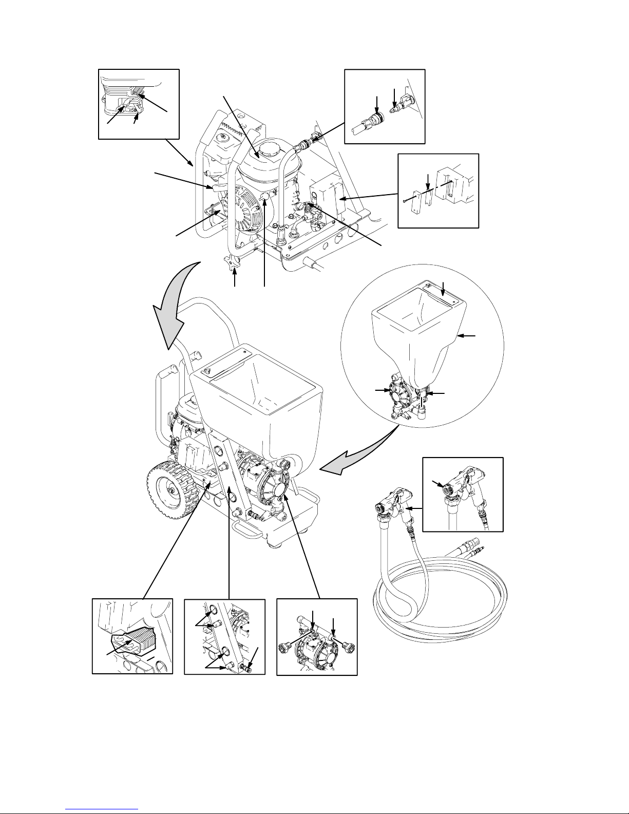
Component Identification
V
A
D
B
Q
R
P
Z
W
F
S
E
G
J
H
4 309916
M
Y
ti3929b
K
L
T
N
U

Component Identification
Note: Letters A--Z used in the chart below to identify specific components, will also be used throughout the text of
this manual to identity those components.
English
A Gas Tank
B Fuel Valve
C Choke
D Throttle Lever
E Engine ON/OFF Switch
F Nozzle Storage
G Hopper
H Hopper Quick Connect
J Diaphragm Pump
K Material Outlet Option 1
L Material Outlet Option 2
M Air Cooler
N Gun Air Outlet Quick Connect
P Air Filter (both sides)
Q Air Line Quick Connect
R Engine Starter Cord
S Motor Lock Knob
T Material (Pump) Air Pressure Gage and Control Knob
U Gun Air Pressure Gage and Control Knob
V Sprayer Quick Connect Air In and AIr ON/OFF Valve
W Pressure Unloader
Y Gun (see manual 308878)*
Z Compressor Power Pack
*Reference numbers used in gun illustrations throughout this manual, coincide with reference numbers used in gun manual
308878
5309916

Preparation
Pressure Relief Procedure
1. Turn engine ON/OFF switch (E) OFF.
2. Open gun air valve (23).
3. Trigger gun, and spray material back into hopper.
Removing and Installing the Hopper
The hopper (G) can be removed from the cart for
cleaning and servicing equipment.
NOTE: Before removing hopper, allow unit to cool
down and/or remove compressor power pack from
cart.
Removing Hopper
1. To remove hopper (G), release the latches on each
side of coupler (H).
2. Lift hopper straight up, off unit. See Fig. 1.
Installing Hopper
1. To install hopper, position coupler over material
outlet and slide it straight down, over the fitting, as
far as it will go.
2. Secure latches by pushing each one up and firmly
into locked position. See Fig. 2.
G
H
Fig. 1
ti3900a
Fig. 2
G
H
ti3900a
6 309916
Preparation
Removing and Installing the Compressor
Power Pack
WARNING
Page 6Page 3
When servicing equipment it may be necessary to
remove the Compressor Power Pack (Z) from the cart.
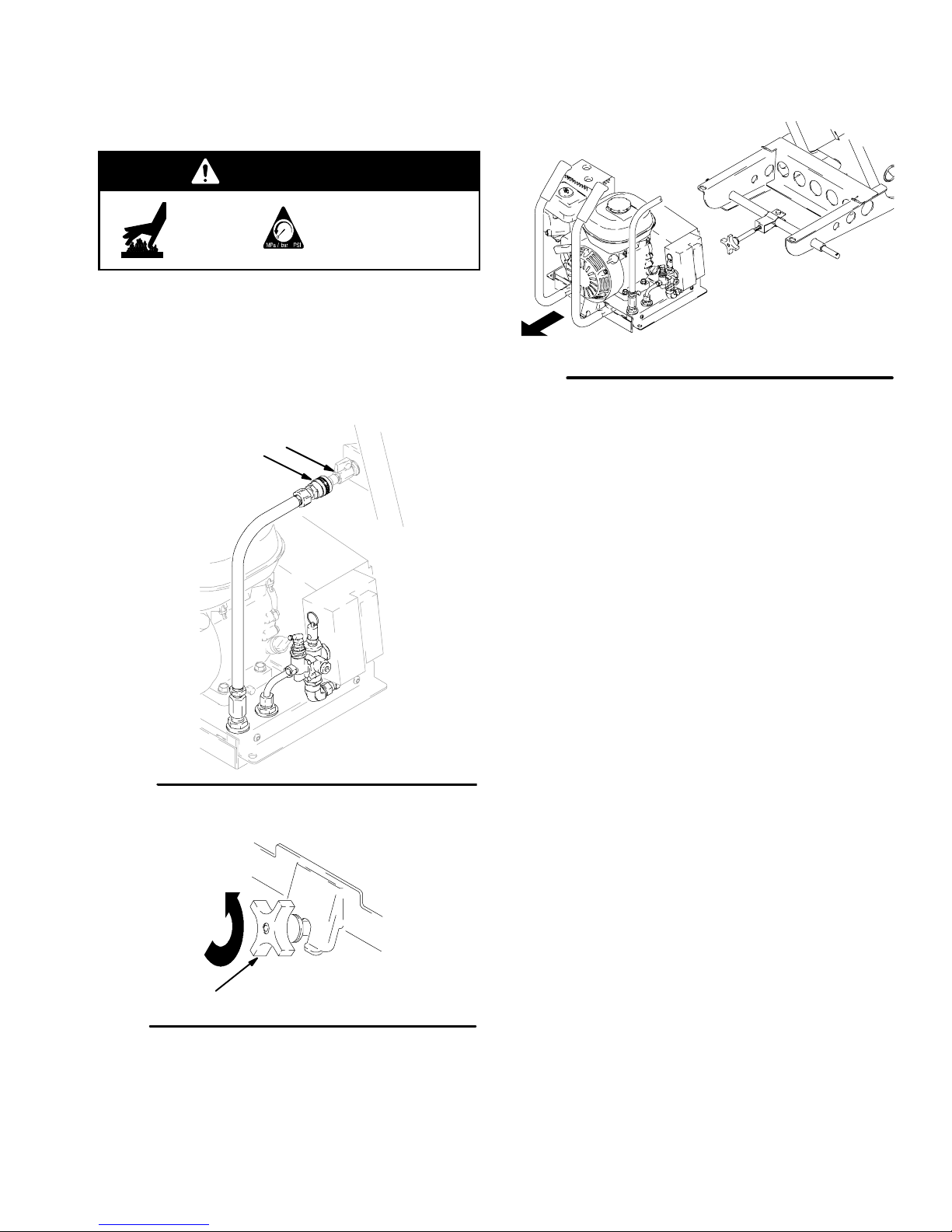
Removing Compressor Power Pack:
1. Disconnect air line quick connect fitting (Q) from
compressor air quick connect fitting (V). See Fig 3.
NOTE: Quick connect fitting will become hot during
operation, see Burn Hazard, page 3.
V
Q
ti3892a
Fig. 5
4. The Compressor Power Pack (Z) slides off back of
cart. See Fig 5.
ti3791a
Fig. 3
2. Loosen knob (S) by turning it counter--clockwise,
relieving tension on the bracket. See Fig. 4.
S
Fig. 4
3. Push knob down. See Fig. 4.
7309916
Installing Compressor Power Pack:
1. Disconnect one end of air hose from air line quick
connect fitting (Q) and the other end of the air
hose from compressor air quick connect inlet fitting
(V).
2. Inspect cart and compressor power pack (Z).
Remove any debris or dirt.
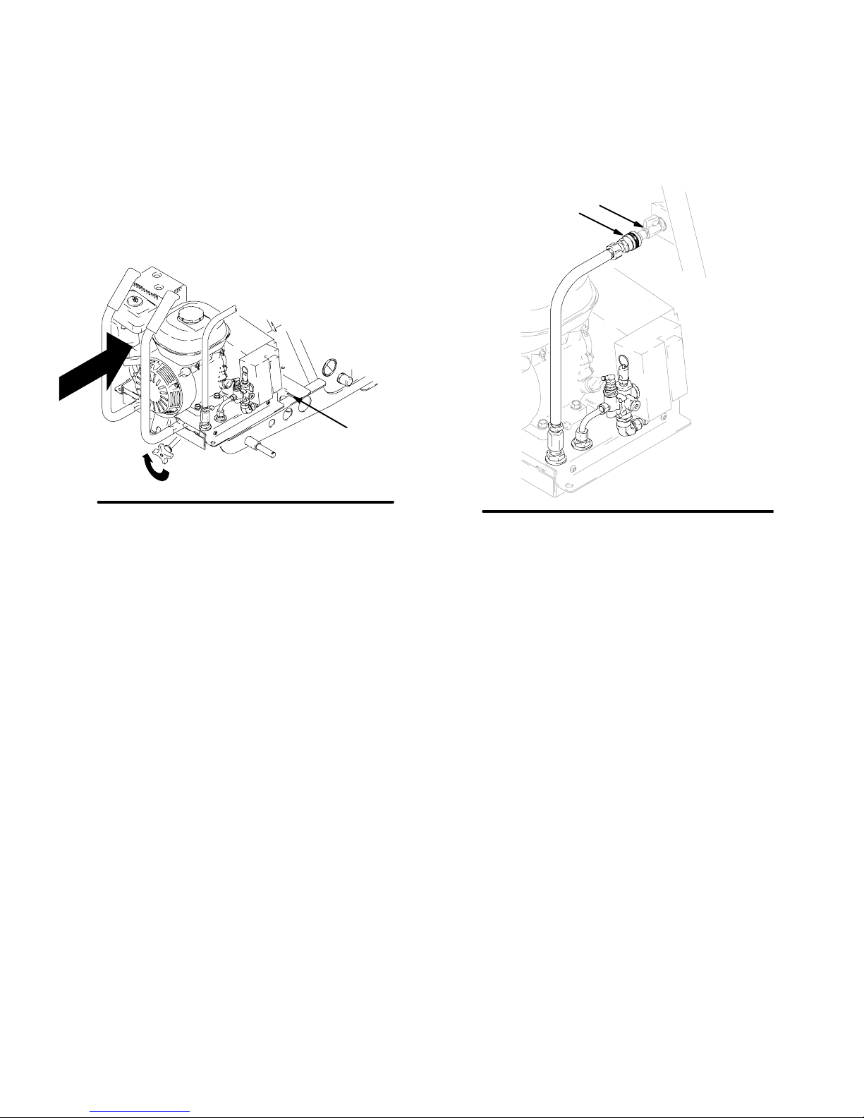
4. Slide Compressor Power Pack (Z) forward until
front edge meets tabs. Fig. 6.
5. Lift and turn motor lock knob (S) until Compressor
Power Pack (Z) is securely attached to the cart.
6. Attach air line quick connect fitting (Q) to compressor air quick connect fitting (V) Fig 7.
3. Using handles, lift compressor power pack (Z) onto
cart frame.
tabs
Fig. 6
ti3782a
V
Q
ti3791a
Fig. 7
8 309916
Engine Maintenance
Changing Engine Oil
WARNING
Page 6
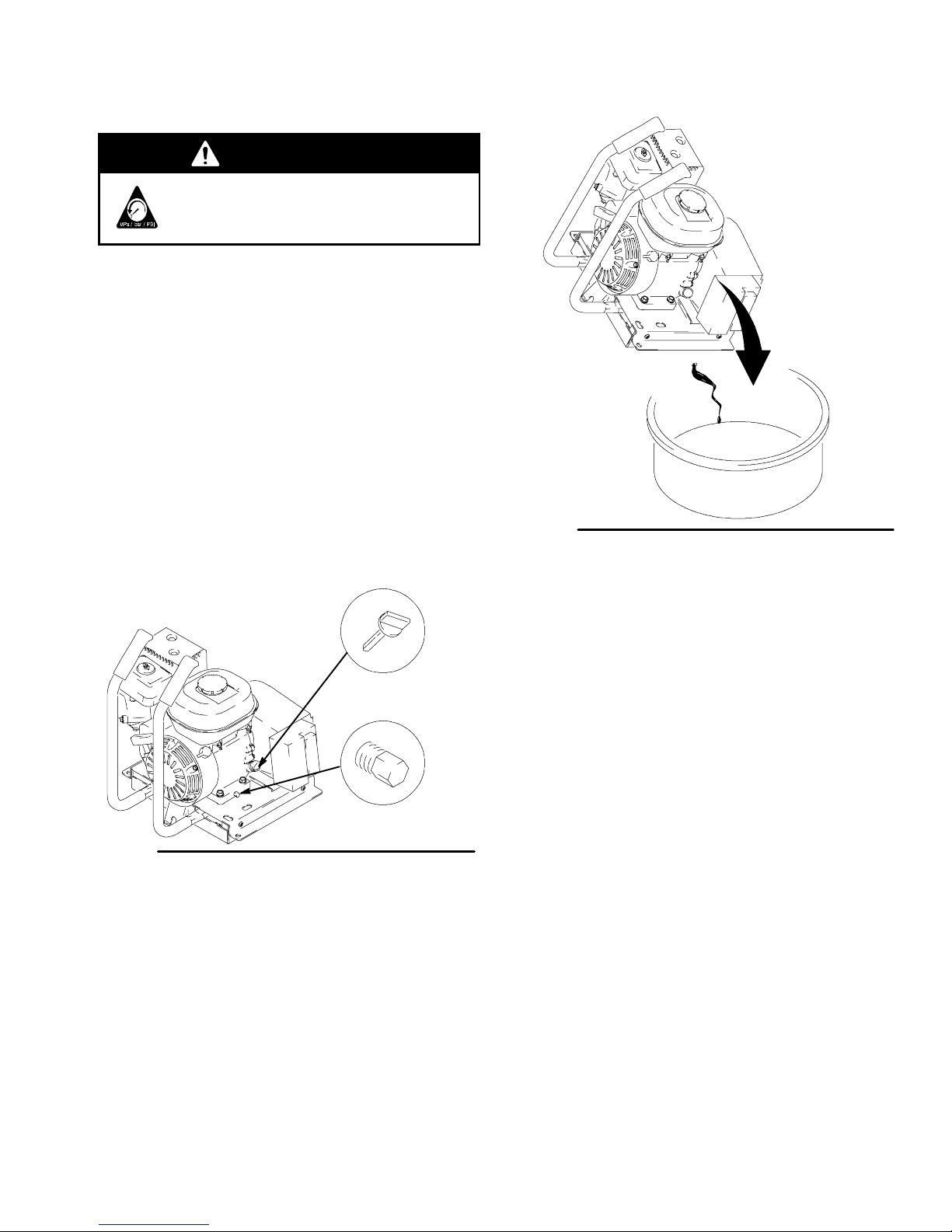
1. Relieve Pressure, page 6.
2. Remove compressor power pack, page 7.
3. Place a suitable container to catch the used oil
below the compressor power pack.
4. Remove drain bolt and filler cap/dip stick. Fig. 8.
5. Tip unit to drain the used oil out of unit. Fig. 9. .
ti4250a
Fig. 9
6. Reinstall drain bolt. Tighten securely. Fig. 8.
7. Place the compressor power pack on a level
surface. Fill to the outer edge of the oil filler hole
with SAE 10W--30 oil. The engine oil capacity is
0.63 qt (0.60 liters). (Refer to the Honda Engines
Owner’s Manual for recommended oil weight.)
Filler Cap/
Dip Stick
Drain Bolt
Fig. 8
For all other engine maintenance, troubleshooting, and repair, see Honda Engines Owner’s Manual.
ti4249a
8. Reinstall the filler cap/dip stick. Tighten securely.
NOTE: Running engine with a low oil level can cause
engine damage. The Oil Alertr system will automatically stop the engine before the oil level falls below the
safe limit. However, to avoid the inconvenience of an
unexpected shutdown, fill to the upper limit and check
oil level regularly.
9. Reinstall compressor power pack on sprayer, page
8.
9309916
 Loading...