

Page 1
INSTRUCTIONS-PARTS
LIST
308–718
This
manual contains important
warnings and information.
READ AND KEEP FOR REFERENCE.
INSTRUCTIONS
First
quality counts.
– For Water-Based Materials Only –
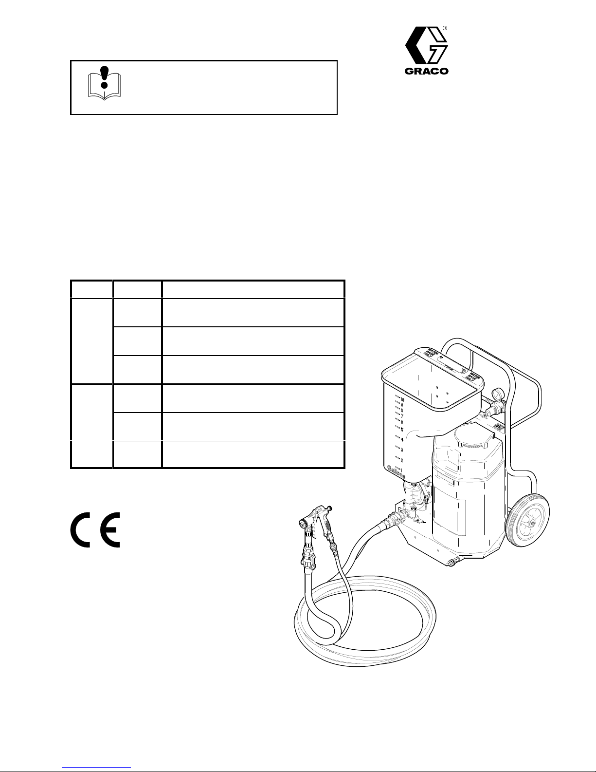
ELECTRIC TEXTURE SPRAYER WITH COMPRESSOR
TexSpray
100 psi (7 bar) Maximum Working Pressure
Power Model Description
120V,
60
Hz
231–780
231–782
Sprayer Model 231–801 with 1 in. fluid
hose, 3/8 in. air hose and T
Sprayer Model 231–801 with 1 in. fluid
hose, 3/8 in. air hose and Flex Gun
Compact HP
rigger Gun
Rev. C
Supercedes Rev. B
choice when
240V,
50 Hz
231–783
231–788
231–790
231–791
Sprayer Model 231–801 with 1 in. fluid
hose, 3/8 in. air hose and 3 ft Pole Gun
Sprayer Model 231–803 with 1 in. fluid
hose, 3/8 in. air hose and T
Sprayer Model 231–803 with 1 in. fluid
hose, 3/8 in. air hose and Flex Gun
Sprayer Model 231–803 with 1 in. fluid
hose, 3/8 in. air hose and 3 ft Pole Gun
rigger Gun
GRACO INC. P.O. BOX 1441
MINNEAPOLIS, MN
COPYRIGHT
Graco
Inc. is registered to I.S. EN ISO 9001
1997, GRACO INC.
7068A
55440–1441
Page 2
Table
of Contents
Warnings 2.
Component
Preparation 5
Startup 9
Spray T
Shutdown
Pump
Troubleshooting 14
. . . . . . . . . . . . . . . . . . . . . . . . . . . . . . . . . . . . .
Identification and Function4. . . . . . . . . . . .
. . . . . . . . . . . . . . . . . . . . . . . . . . . . . . . . . . . .
. . . . . . . . . . . . . . . . . . . . . . . . . . . . . . . . . . . . . . . .
echniques
and Cleanup
Maintenance
. . . . . . . . . . . . . . . . . . . . . . . . . . . .
. . . . . . . . . . . . . . . . . . . . . . .
. . . . . . . . . . . . . . . . . . . . . . . . . . .
. . . . . . . . . . . . . . . . . . . . . . . . . . . . . . .
10.
12.
14.
Symbols
Warning Symbol
WARNING
This
symbol alerts you to the possibility of serious
injury or death if you do not follow the instructions.
WARNING
EQUIPMENT MISUSE HAZARD
INSTRUCTIONS
Equipment
D
This equipment is for professional use only
misuse can cause the equipment to rupture or malfunction and result in serious injury
Compressor
Cooler
Parts
– Sprayer
Wiring
Accessories 23
Technical
Graco
Graco Warranty 24.
Repair
Repair
Diagram
Phone Number
. . . . . . . . . . . . . . . . . . . . . . . . . . . . . . . .
. . . . . . . . . . . . . . . . . . . . . . . . . . . . . .
. . . . . . . . . . . . . . . . . . . . . . . . . . . . . .
. . . . . . . . . . . . . . . . . . . . . . . . . . . . . . . . . .
Data
. . . . . . . . . . . . . . . . . . . . . . . . . . . . . . .
. . . . . . . . . . . . . . . . . . . . . . . . . . . . .
. . . . . . . . . . . . . . . . . . . . . . . . . . .
. . . . . . . . . . . . . . . . . . . . . . . . .
Caution Symbol
CAUTION
This
symbol alerts you to the possibility of damage to
or destruction of equipment if you do not follow the
instructions.
.
.
17.
19.
22.
22.
23.
23.
D
Read all instruction manuals, tags, and labels before operating the equipment.
D
Use the equipment only for its intended purpose. If you are not sure, call Graco T
tance at 1–800–543–0339.
D
Do not expose the system to rain. Always store the system indoors.
D
Do not alter or modify this equipment. Use only genuine Graco parts.
D
Check equipment daily
D
Do not exceed the maximum working pressure of the lowest rated component in your system. This
equipment has a
pressure.
D T
o reduce the risk of serious injury
the
Pressure Relief Procedure
D
Do not use hoses to pull equipment.
D
Route hoses away from traffic areas, sharp edges, moving parts, and hot surfaces. Do not expose
Graco hoses to temperatures above 55_C (130_F) or below –40_C (–40
D
Do not lift pressurized equipment.
. Repair or replace worn or damaged parts immediately
100 psi (7 bar) maximum working pressure at 100 psi (7 bar) maximum air
, including electric shock and splashing fluid in the eyes, follow
on page 7 before checking or repairing the compressor
_F).
echnical Assis
.
.
-
2
308–718
Page 3
TOXIC FLUID HAZARD
WARNING
Hazardous
inhaled, or swallowed.
Know the specific hazards of the fluid you are using.
Store hazardous fluid in an approved container
state and national guidelines.
Always wear protective eyewear
solvent manufacturer
Pipe and dispose of exhaust air safely
Never directly inhale compressed air
fluid or toxic fumes can cause serious injury or death if splashed in the eyes or on the skin,
. Dispose of hazardous fluid according to all local,
, gloves, clothing and respirator as recommended by the fluid and
.
, away from people, animals, and food handling areas.
. Compressed air may contain toxic vapors.
FIRE AND EXPLOSION HAZARD
Improper
result in a fire or explosion and serious injury
grounding, poor ventilation, open flames or sparks can cause a hazardous condition and
.
The system is for use only with water-based materials.
ment wetted parts. Refer to the Technical Data
and solvent manufacturer’s warnings.
Ground the equipment. Refer to
Grounding
section of all equipment manuals. Read the fluid
on page 5.
Use fluids compatible with the equip
-
If there is any static sparking or you feel an electric shock while using this equipment,
ing immediately. Do not use the equipment until you identify and correct the problem.
Provide fresh air ventilation to avoid the buildup of flammable fumes from solvents or the fluid
being sprayed.
Keep the work area free of debris, including solvent, rags, and gasoline.
Locate the sprayer at least 20 ft (6.1 m) away from any explosive vapors, due to arcing parts.
Comply with all applicable local, state, and national fire, electrical, and safety regulations.
stop spray-
308–718
3
Page 4
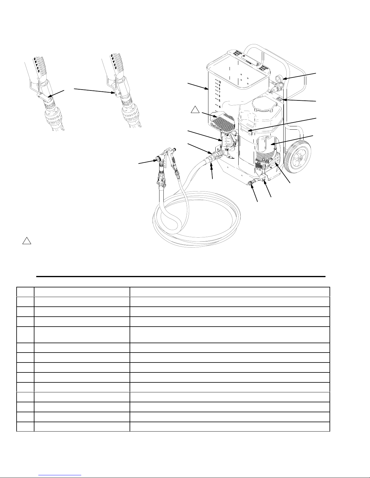
Component
Identification and Function
C
Closed
1
Located inside
hopper
N
Open
7136A
H
J
D
1
L
K
F
B
A
O
M
G
E
Fig. 1
A Air
B
C
D
E Compressor
F Pump
G
H
J Hopper
K
L
M
N
O
Outlet
Pump Outlet Fitting Provides connection for hose and fluid supply to spray gun
Air Pressure Regulator
ON/OFF Switch
Heat Exchanger
Spray Gun
Air Filter
Material Screen
Auxiliary Air Compressor Port
Gun Air V
Air Line Drain V
alve
alve
7069A
Provides quick disconnect connection for air supply to spray gun
Adjusts air pressure to control air pressure to pump
Power switch that controls 120/240 V
Open frame AC motor
air compressor
Pressurizes fluid to be sprayed through spray gun
Reduces temperature of air from compressor
Uses compressor air to break up and spray texture material
Holds texture material;12 gallon maximum capacity
Filters incoming air to the compressor
Filters material to the pump
Provides connection to replacement or supplemental air compressor
Shuts of
Allows air line moisture accumulation to be drained
f air supply to spray gun
, 1 phase, with two cylinder oil-less single stage
ac power to sprayer
4
308–718
Page 5
Preparation
Compressor Break-in
The
first time you use the system, run the compressor
under no load to break it in, improve performance and
lengthen its life.
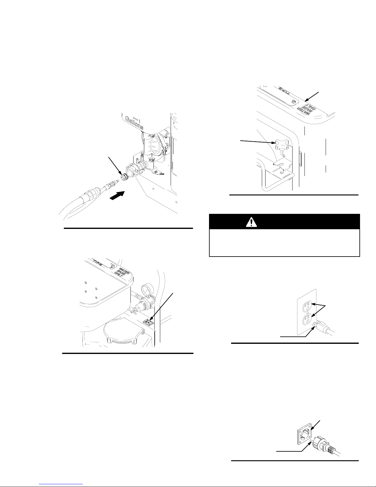
1.
Connect the air hose to (A) and the gun to the
other end of the hose. Open gun air valve (423)
and turn air restrictor valve (424) all the way to the
+ position. See Fig. 2 and 9.
A
2. T
o install the hopper
over the pump inlets while tilting the hopper very
slightly forward. As you engage the inlets,
straighten the hopper and push down. V
inspect the pump inlets to be sure the hopper is
fully engaged. T
P
, position the hopper drain
ighten the knob (P). See Fig. 4.
J
isually
Fig. 2
2. T
urn the ON/OFF switch (D) ON. Run the system
for 15 minutes. T
Fig. 3
urn the switch OFF
. See Fig. 3.
7070A
D
7078A
Hose Size and Lengths
The
system comes with a hose set consisting of a 1 in.
ID x 25 ft (25 mm x 7.6 m) fluid hose and a 3/8 in. ID
air hose. The 1 in. hose set includes an adapter hose
between the gun and main hose. See parts, page 22.
Use the shortest length possible when spraying. In
creasing hose length decreases sprayer performance.
Do not use more than 75 ft (23 m) of fluid hose.
-
Removing and Installing the Hopper
Fig. 4
Grounding
WARNING
Improper installation or alteration of the grounding
plug will result in a risk of electric shock, fire or
explosion that could cause serious injury or death.
120 V
ac Systems
1.
This equipment requires a 120 V
circuit with a grounding receptacle. See Fig. 5.
Grounding
Fig. 5
2. Do
3.
240 V
1.
2.
3.
not alter the ground prong or use an adapter
See page 6 for Extension Cord Requirements.
ac Systems
This equipment requires a 240 V
circuit with a grounding receptacle. See Fig. 6.
Do not alter the ground prong or use an adapter
See page 6 for Extension Cord Requirements.
Prong
ac, 60 Hz, 15A
Grounded
Outlets
ac, 50 Hz, 6A
Grounded
Outlet
7071A
.
.
1. To
remove the hopper (J), loosen the knob (P) until
about 1 in. of thread shows. Lift the hopper straight
up of
f the unit. See Fig. 4.
Fig. 6
Grounding
Prong
308–718
5
Page 6
Preparation
Setup the System
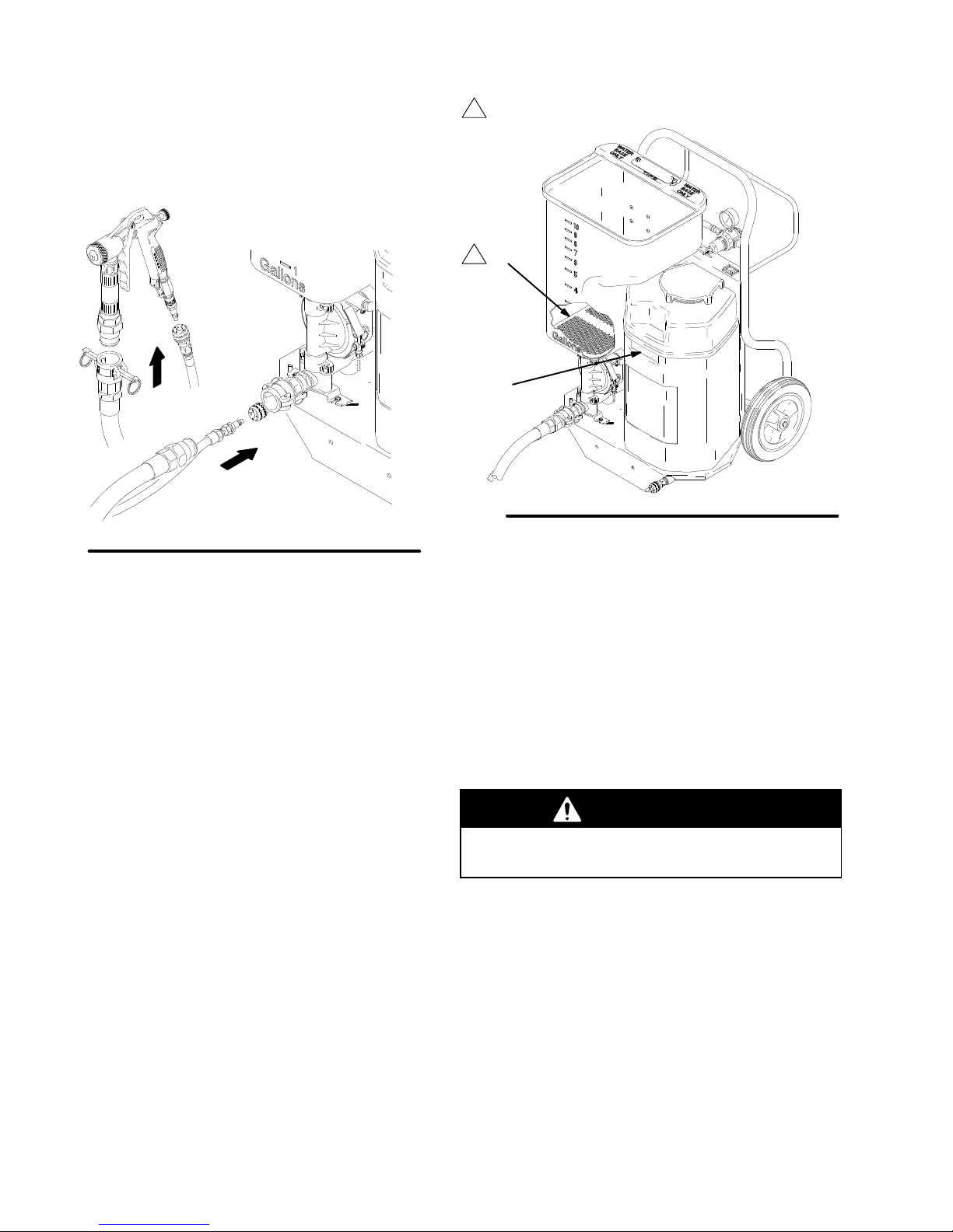
1. Connect
Fig. 7
the hoses and gun as shown See Fig. 4.
7072A
1
Located inside hopper
L
1
K
Fig. 8
Using an Auxiliary Air Compressor
07073A
2.
Be sure the air filter (K) and the material screen (L)
are in place. See Fig. 8.
3.
Plug the power cord into a properly grounded,
120V
, 15A (240V
, 16A) (minimum) outlet.
Extension Cord Requirements:
Use
a cord with an undamaged, 3 prong plug.
For up to 25 ft (7.6 m) cord, use three wires, 12
A
WG (1.5 mm2) minimum.
For 25 to 50 ft (7.6 to 15.2 m) cords, use three
wire, 10 A
Do not use an ungrounded adapter
WG (2.5 mm2) minimum.
.
An
external air compressor may be connected (adapt
er included) to the auxiliary air compressor port (L) to
supplement, or replace, the internal air compressor of
the TexSpray
Additional air is needed to break up hard-to-spray
materials or
When the job site does not have the proper electric
service, but a gasoline-powered compressor is
available.
. This may be useful when:
,
WARNING
Over pressurizing the system may cause compo
nent rupture and resulting in serious injury
T
o reduce the risk of over pressurizing the system, do
not use a compressor with an output pressure greater
than 100 psi (7 bar
greater than 6.8 scfm at 90 psi (0.19 m3/min. at 6.3
bar
, 60.3 kPa).
, 70 kPa), and/or with a delivery
-
.
-
6
308–718
Page 7
Preparation
WARNING
PRESSURIZED EQUIPMENT HAZARD
The system pressure must be manually relieved to
prevent the system from starting or spraying acci
dentally. T
dental spray from the gun, splashing fluid, or
moving parts, follow the
dure
Pressure Relief Procedure
1. Shut
2. T
3.
Open the gun air valve (handle parallel with valve
body).
o reduce the risk of an injury from acci
Pressure Relief Proce
whenever you:
are instructed to relieve the pressure,
stop spraying,
check or service any of the system equipment,
or install or clean the spray nozzle.
of
f the system.
rigger the gun back into the hopper
.
5.
Always have the fluid hose installed when there is
material in the hopper
hopper will drain out through the pump.
-
-
-
The motor has a thermal overload switch which
shuts down the motor if it overheats.
T
o reduce the risk of serious bodily injury due to the
system restarting unexpectedly
ON/OFF switch (D) OFF if the motor shuts down.
See Fig. 3.
. If the hose is removed, the
WARNING
, always turn the
CAUTION
Damage to the power cord may result from uninter
rupted operation. Do not operate sprayer at maxi
mum pressure for more than 1 hour in any 2 hour
period.
Gun air valve
1
shown open
-
-
4.
Unplug the system.
5.
Place a rag over the pump outlet fitting (B) and
slowly open the cam locks to relieve residual
pressure.
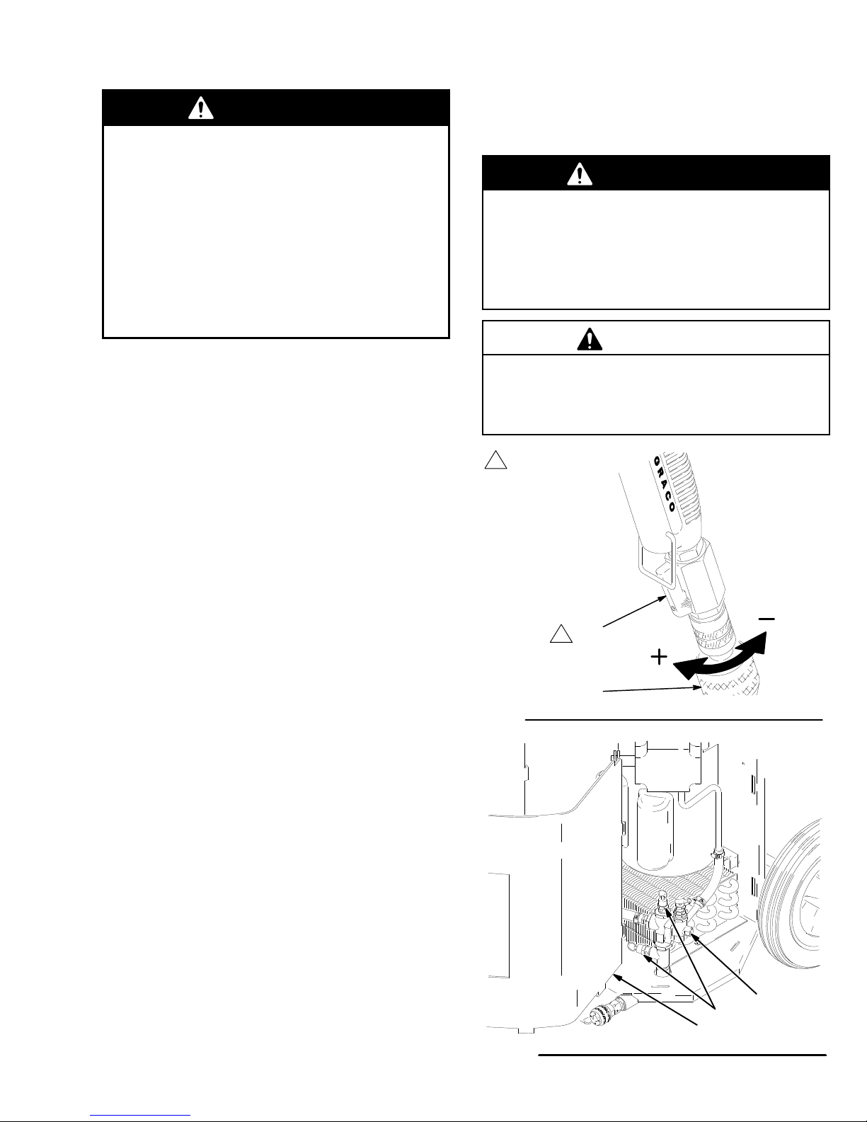
Operation Characteristics
1. Always
relieved!
How to relieve pressure: Be sure the gun air
valve (423) and air restrictor valve (424) are open.
This relieves compressor air every time you shut
of
2.
Air bleeds from the gun nozzle whenever the gun
air valve (423) is open. Close the valve to stop the
air
during priming. See Fig. 9. See page 10 for more
gun characteristics.
3.
A compressor unloader valve (10) with two pres
sure relief valves (W) is located under the com
pressor guard (1
causing a popping sound, when air flow at the gun
is too restricted. The valve resets automatically
when the air flow is increased. See Fig. 10.
4.
If air exhausts through the pump muf
pump starts and then stops, see texture pump
manual 308–781.
start the system with the compressor air
f the system. See Fig. 9.
, if desired. Otherwise, it can stay open except
1). Air escapes from the valve,
fler or the
423
1
424
Fig. 9
-
-
W
11
Fig. 10
7132A
10
7074A
308–718
7
Page 8
Preparation
Wet the Hose Before Pumping Texture
Material
Wet
the inside of the hose before each use to flush out
sediment and to prevent the texture material from
packing out the hose.
1.
The hopper (J) capacity is 12 gallons (30 liters).
Pour a gallon of clean water into the hopper
Close the gun air valve (423); the system primes
2.
easier if no air is supplied to the gun.
3. T
urn the ON/OFF switch (D) ON. T
into the hopper (J). T
water for a few minutes and wet the inside of the
fluid hose.
4. T
rigger the gun into a pail to lower the water to the
hopper strainer (L) level.
5. T
urn the ON/OFF switch (D) OFF
6.
Open the gun air valve (423) to relieve the com
pressor air
Closed
.
rigger the gun to circulate the
423
rigger the gun
.
Open
Mix the Material
CAUTION
This
system is designed for use with only certain
types of material. Any other use could seriously
.
-
damage the unit.
Do not use any solvent-based materials. Use
only water-based materials.
Use only simulated acoustic and gypsum-based
wall texture materials in this system.
Do not spray cementious materials, which will
damage the pump.
Proper material mixture is essential. The pump
won’t operate if the material is too thick.
Mix material in a separate container and pour into the
hopper for best results.
Slowly add one bag of texture material to clean water
as instructed on the bag instructions. Agitate to a
smooth, lump-free consistency. Thin the material as
needed before pouring it into the hopper. For the
best results, do not use partial bags of material.
Fig. 11
7136A
8
308–718
Page 9

Prime the System
Startup
1. Fill
2.
3.
4.
NOTE:
aggregate material, disconnect the hose at the gun,
prime the pump and hose, and circulate material back
into the hopper for 10 seconds. T
Install the gun and tip.
5. T
6.
the hopper (J) with the prepared texture
material.
Install a tip. Refer to the T
page 10.
Open the gun air valve (423) to be sure air pres
sure is relieved and then close it again; the system
primes easier if no air is supplied to the gun.
Be sure there are no kinks in the hose, which
restricts fluid flow
If spraying a simulated acoustic and coarse
urn the ON/OFF switch (D) ON. T
into a pail. When texture material appears at the
tip, move the gun to the hopper and circulate until
there is a solid stream of texture material.
See SPRA
for how to balance the pump and gun adjustments
for a good spray pattern.
.
Y TECHNIQUES on pages 10 and 1
ip Selection Chart on
urn of
f the pump.
rigger the gun
-
1
J
L
1
1
Located inside hopper
Fig. 12
D
7073A
308–718
9
Page 10

Spray
T
echniques
Tip Selection Chart
Application Tip
Fog
Simulated
Acoustic
Orange Peel
Splatter Coat
Knockdown
1
Control air volume with the gun air flow valve (424).
2
For more material volume, try a larger orifice tip.
Orifice
1/8 in.
3/16 in.
(fine, or small
confined areas)
1/4 in.
(fine to medium)
5/16 in.
(coarse)
1/8 to 3/16 in.
1/4 to 5/16 in.
5/16 in.
2
Air V
High
Medium to
High
Medium to
High
Low to
Medium
Low
olume
1
Adjusting the System
Sufficient
atomization requires testing to balance the compressor
air to the gun and pump and to select the right tip.
Keep in mind these important points when adjusting
the gun:
fluid output (volume and pressure) and good
To Get Less Material
Try
any one or a combination of these methods.
1.
Screw in the gun fluid regulator knob (418).
2.
Use a smaller tip.
3.
Reduce pump pressure. Use the regulator
To Get More Material
Try
any one or a combination of these methods.
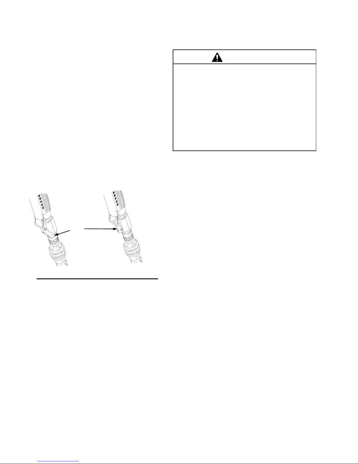
1. T
urn the air flow valve (424) to decrease (
Unscrew the fluid knob (418) to increase trigger
2.
travel.
Note:
Maximum trigger travel occurs when trigger
bail (401) can hold trigger in open position. Fig. 13.
3.
Use a shorter hose.
4.
Use a thinner material mixture.
5. T
ry a larger orifice tip.
6.
Increase pump pressure. Use the regulator
.
–).
.
1.
Read all of pages 10 and 1
2.
Refer to the chart above for tip selection. Consider
the size of aggregate in the material and the
coarseness of the spray pattern. Remember
larger the tip, the heavier the pattern.
3.
The compressor provides air to both
the pump; the more air you supply to the gun, the
less that is available for the pump.
4.
All spraying adjustments are made at the gun;
material pressure and flow rate is made by adjust
ing the regulator
5.
Start the sprayer with the gun air flow valve (424)
at its maximum setting (fully +). If needed, slowly
decrease the gun air flow until you get a good
spray pattern. Use the minimum amount of air at
the spray gun to achieve the proper spray pattern
and minimize bounce back.
6. T
urning the air flow valve (424) toward
(+)
increases air flow
decreases texture material output
.
1 first.
the gun and
through the gun which
.
, the
CAUTION
T
urning the knob (418) out too far will remove the
knob and the gun will not shut of
released.
7. T
est the spray pattern on cardboard. Hold the gun
18 to 30 in. (457 to 762 mm) from the surface. Use
this spraying distance for most applications.
8.
Overlap each stroke 50% in a circular motion.
418
401
f when the trigger is
IN
OUT
424
urning the air flow valve (424) toward
7. T
(–) decreases air flow through the gun
increases pump output.
10
308–718
which
Fig. 13
423
Page 11

Spray
T
echniques
How to Prevent Material Surge at the
Beginning of a Spray Pattern
Squeeze
tion while moving the gun quickly
the trigger slowly to the fully triggered posi
.
For Continuous Spraying
Use
the trigger bail (401) to hold the trigger open to
reduce operator fatigue.
Check Material Consistency Periodically
Check
and thin the material as needed to maintain the
proper consistency
and slow down production or af
pattern.
. The material may thicken as it sits
fect the spray
418
-
401
423
Fig. 14
IN
OUT
424
308–718
11
Page 12

Shutdown
and Cleanup
1. Fig.
2. T
3.
NOTE:
page 5.
4. T
5.
6.
7. T
8. T
15. and 16. Be sure the compressor pressure
is relieved – gun air valve (423) open. Close the
gun air valve again. T
ON.
rigger the gun into a pail to lower the fluid to the
hopper strainer (L) level. See Fig. 16.
Fill the hopper (J) about half full with clean water
depending on the hose length. Clean the inside of
the hopper with a brush, if needed.
The hopper can be removed for cleaning. See
rigger the gun into a pail until most of the texture
material is pumped out.
Fill the hopper with clean water
Start the sprayer
T
rigger the gun into the hopper to circulate the
remaining water for a few minutes.
rigger the gun into the pail to empty the hopper
and the hose.
urn the ON/OFF switch (D) OFF
air valve (423) to relieve compressor pressure.
See Fig. 15. and 16.
urn the ON/OFF switch (D)
.
. Spray half the water into a pail.
. Open the gun
NOTE:
not freeze. If it does freeze, thaw it thoroughly before
using it.
10.
,
11.
12.
NOTE:
between texture, knockdown and orange peel. A dirty
pump can release a piece of texture into the finish.
13.
In cold weather
Remove the air filter (21), wash it thoroughly with
soap and water
Clean and dry the gun. Oil the gun daily with a few
drops of SAE–10 light oil at the points indicated in
Fig. 15.
When the unit cools, rinse the cooler with plain
water.
Keep the pump and hose clean when switching
Drain the frame air line after each use.
a.
Open the drain cock valve (S). See Fig. 16.
b. T
urn the ON/OFF switch ON.
c.
Rock the sprayer back and forth slightly to
drain any moisture in the air line.
, store the system where it will
, and reinstall it. See Fig. 16.
9. Keep pump wet during non-use.
(360 ml) of clean water into the hopper drain.
Pour 12 oz.
CAUTION
T
o keep the unit in good operating condition, always
clean it thoroughly and prepare it properly for
storage, even for overnight storage. Pay particular
attention to these areas:
Keep the pump wet during non-use to help
prevent contaminants from drying inside the
pump.
Clean the sponge filter at least daily
allows contaminates into the compressor and
eventually into the pump, resulting in poor perfor
mance and damage.
Removing the material hose will allow the pump
to drain rapidly
connected to keep the pump wet.
Oil the gun daily
. The material hose must remain
.
. A dirty filter
d. T
urn the ON/OFF switch OFF
e.
Close the drain cock valve.
-
.
Oil the pump air inlet. See Pump Maintenance in
the T
exture Pump Manual 308–781.
12
308–718
Page 13

Shutdown
and Cleanup
1
Closed
Fig.
L
K
15
423
Open
7136A
1
1
Oil here
Fig. 17
D
0631
Fig. 16
S
7092A
308–718
13
Page 14

Pump
For
pump maintenance, troubleshooting and/or repair
Maintenance
, see Manual 308–781.
Troubleshooting
WARNING
T
o reduce the risk of injury
System Troubleshooting
PROBLEM CAUSE SOLUTION
Compressor
No material output from pump.
Unloader Malfunctions
does not start.
, follow the
T
rapped air pressure.
Improper power supply
T
ripped thermal overload in motor.Check extension cord. A maximum
Not enough air pressure to pump.
Material too thick.
Unloader unloads too early
Pressure Relief Procedure
Relieve air pressure by connecting
air hose and opening gun air valve.
.
Connect to power supply rated for
your sprayer
length of 25 ft of 12 A
10 A
used for 120 Vac, 15A. (A maximum
length of 8 m of 1.5 mm2 or 15 m of
2.5 mm2 may be used for 240 V
16A). Allow unit to cool down and
try again.
Note: Remove extension cord and
plug unit directly into outlet. If unit
operates correctly
extension cord problem.
Clean filter
fan. Allow unit to cool down and try
again.
Have motor serviced.
Shut of
air pressure to the pump to maxi
mum. T
increase.
Thin material. Material must be
mixed thoroughly to a consistency
that immediately folds back in as
you draw your finger through the
surface of the material.
Replace unloader
on page 7.
WG extension cord may be
.
WG or 50 ft of
ac,
, this indicates an
, air cooler and cooling
f air at the gun and increase
-
urn regulator clockwise to
.
Unloader stutters
Unloader unloads to late
14
308–718
Page 15

Troubleshooting
PROBLEM CAUSE SOLUTION
No material output from pump
(continued)
Air
valve is stalled.
Reset the pump. See Fig.
1.
Open air to the gun.
Note:
Under normal use the
duck bills and diaphragms will
wear out at 20,000 gallons. If the
material being sprayed has a
stone aggregate the expected
life is 3,000 to 4,000 gallons.
122
Gun or nozzle plugged.
Hose plugged or too small.
Leaky or damaged duck bills.
Pump needs repair
.
2. T
urn the unit of
3.
Move the reset handle (122) in
the direction of least resistance
(about 15 lb. of force needed).
4.
If the reset handle can not be
moved in either direction, the
pump is plugged. Flush the
pump out or stick a wooden
7079A
dowel down each of the intakes
to clear it.
5.
If the reset handle moved and
the pump still does not pump,
see troubleshooting in pump
manual 308–781.
6. T
urn the ON/OFF switch ON
and trigger the gun into the hop
per until there is a solid stream
of texture material.
Note: If the pump continues to
stall:
1.
Thin the material. See above
2.
Clean hose and gun. See below
3. T
ry a 1–1/4 in. hose. See below
4.
See troubleshooting in pump
manual 308–781.
Relieve pressure, remove gun from
material hose and cycle pump.
Note: A plugged gun or nozzle may
cause the hose and pump to plug.
If necessary flush hose and pump
with clean water before cycling ma
terial through the hose with the gun
removed.
Relieve pressure, flush hose with
clean water and/or try a 1–1/4 in.
hose.
Clean and inspect duck bills.
Note: Match pump part number
with the correct pump breakdown in
308–781. Not all texture pumps
have the same assembly order
See pump manual 308–781.
f.
-
-
.
308–718
15
Page 16

Troubleshooting
PROBLEM CAUSE SOLUTION
Material pulses or surges.
Speed of application too slow
Pattern too fine or too much
overspray
Pattern too coarse. Material too thick.
T
riggering too fast.
Leaky or damaged duck bills.
Not enough air pressure to pump.
Material too thick.
Nozzle is too small.
Hose plugged or too small.
Leaky or damaged duck bills.
Pump needs repair
Material too thin.
Air pressure at gun is too high.
Fluid delivery is too low
Air pressure at gun is too low
Fluid delivery is too high.
Squeeze trigger slowly to fully open
position
circular
Clean and inspect duck bills.
Note: Match pump part number
with the correct pump breakdown in
308–781. Not all texture pumps
have the same assembly order
Shut of
air pressure to the pump to maxi
mum. T
increase.
Material must be mixed thoroughly
to a consistency that immediately
folds back in as you draw your fin
ger through the surface of the ma
terial.
Increase nozzle size.
Relieve pressure, clean hose or try
a 1–1/4 in. hose.
Clean and inspect duck bills.
Note: Match pump part number
with the correct pump breakdown in
308–781. Not all texture pumps
have the same assembly order
.
.
.
See pump manual 308–781.
Thicken material. Material must be
mixed thoroughly to a consistency
that immediately folds back in as
you draw your finger through the
surface of the material.
Decrease air to gun at gun fitting.
Increase nozzle size
Increase air pressure to pump and/
or decrease air to gun at gun fitting
T
spray technique on pg. 10.
Thin material. Material must be
mixed thoroughly to a consistency
that immediately folds back in as
you draw your finger through the
surface of the material.
Increase air to gun at gun fitting.
Decrease nozzle size
Decrease air pressure to pump and/
or increase air to gun at gun fitting
T
spray techniques on pages 10
and 1
while moving gun quickly in
motion.
f air at the gun and increase
urn regulator clockwise to
urn fluid knob out on gun. See
urn fluid knob in on gun. See
1.
a
.
-
-
-
.
16
308–718
Page 17

WARNING
HOT
SURF
Be sure the compressor duct work is
cool before removing it. If the sprayer
was operated recently
and can cause burns!
Compressor
ACE HAZARD
, it will be very hot
Repair
3.
Fig. 18. Remove two screws (26A) and loosen two
screws (26B). Move pump (35) out of the way
4.
Remove filter cover (20).
5.
Remove two screws (7).
6.
Remove compressor cover (23) and air filter (K).
.
NOTE:
serviced.
1.
2.
Clean the cooler whenever the compressor is
Follow the
Fig. 1. Remove hopper (J).
20
7
23
35
26A
Pressure Relief Procedure
on page 2.
7.
Remove compressor guard (16).
8.
Remove grounding screw (36) and two leads (U)
from bottom of switch (9).
Continued on page 18.
9
76
36
U
K
16
Fig. 18
26B
308–718
18
17
Page 18

Compressor
Repair
9. Fig.
10.
11.
12.
13.
19. Tip T
Loosen hose clamps (28) and pull out hose (31).
Remove two screws (76) and saddle-mount
cups (77).
Place a piece of cardboard between compressor
and cooler to protect cooler from damage during
step 13.
Carefully remove compressor wires while lifting
compressor up and away from cart frame (1).
exSpray horizontal.
Compressor Repair
If
you are rebuilding the compressor (18), see DeVIL
BISS manual OEM–4000–A.
Graco of
sor
NOTE:
vice center locations, call your Graco distributor or
1-800-888-2468.
fers repair kits for the two cylinder compres
. The repair kits are listed in the
For repair assistance or for compressor ser
Accessories.
-
-
Compressor Installation
1. Fig.
2.
-
NOTE:
A
18 and 19. Clean air filter (K).
Reassemble sprayer in reverse order of
Compressor Removal
See the wiring diagram on page 22.
28
procedure.
31
76
77
A
Fig. 19
18
308–718
7081A
Page 19

WARNING
HOT
SURF
Be sure the compressor duct work is
cool before removing it. If the sprayer
was operated recently
and can cause burns!
ACE HAZARD
, it will be very hot
Cooler
Repair
1.
Follow the
page 2.
2.
Loosen the clamp (28) on the hose (29) and
remove the hose from the cooler (27). See Fig. 20.
3.
Remove the screws (7) and cooler (27). Clean and
inspect for leaks, dents or plugging with dust. See
Fig. 20.
Pressure Relief Procedure
on
28
29
27
A
7
A
Fig. 20
308–718
7082A
19
Page 20

Notes
20
308–718
Page 21

Model
231–801 and 231–803
Parts
20
8
18a
– Sprayer
7
A
23
22
10
21
11
7
14
60
13
71a
71b
18
23(Ref)
A
29(Ref)
7
27
17
16
15
71d
18b
18c
24
7
51
24
25
31
12
B
11 2829
32
79
30c
30d
7
28
B
9
33
30d
30b
30a
11
36
1
30
6
26
39
38
37
2
3
71c
72
71e
72a
75
72
72b
White
Black
34
White
Black
37(Ref)
9(Ref)
Black
Green
308–718
White
Green
36(Ref)
7083B
21
Page 22

Parts
Model
231–801 and 231–803, Series A
with 1 in. fluid hose, 3/8 in. air hose, and gun.
– Sprayer
Ref
No
1 192–243
2 113–807
3 113–958
4 189–265
6 191–948
7 113–974 SCREW
8 108–471
9 111–961
10 113–673 GAUGE 1
11 100–606
12 208–536
13 239–753 PUMP 1
14 239–282
15 290–440
16 191–941
17 191–945 FIL
18
Part No.
Description Qty
FRAME, T
WHEEL, flat free urethane
RING, retaining, external
LABEL, danger
COVER, tool box
KNOB, pronged
SWITCH, rocker
PIPE, close
COUPLER, line, air
HOPPER, 12 gallon
LABEL, identification
GUARD, compressor
TER, air
COMPRESSOR, air
exSpray twin
, mch, sltd, hex wash hd
, twin cylinder
14
includes 18a through 18c
Model 231–801
239–743 120V
239–744 220V
18a DAC–244 .
18b SSF–297 . SCREW
18c ACG–18 . CUP
20 191–944
21 113–406
22 162–453 NIPPLE 1
23 113–813
24 189–286
25 189–285
26 103–394
27 191–940
28 113–382 CLAMP
29 113–810
30 239–058 REGULAT
30a 106–228 .
30b 113–809 . REGULAT
30c 113–385 .
30d 113–811 . VAL
, 60 Hz, 15A
Model 231–803
, 50 Hz, 12A
SHROUD, front
, 1/4 x 1.125 in.
, saddle–mount
COVER, filter
AIR REGULA
HOSE, air
LABEL, warning, moving
LABEL, caution, hot
BUSHING, snap
COOLER, air
HOSE, air
TEE, street
BARB, hose
VE, safety
TOR 1
, cpld, 3/8 in. x 25 in.
, hose
, 3/8 in. x 13 in.
OR, unloader assy
OR, unloader
Ref.
No.
31 113–812
1
32 290–491
2
33 192–249 CLIP
2
34 239–289 CONDUCT
2
35 186–620
1
36 111–593 SCREW 1
37 113–799 INLET
1
38 192–149
1
39 106–520 SCREW
41 290–539
4
43 169–970
2
46 113–397
48
1
1
1
1
51 113–491 CLAMP 1
60 192–211 FIL
71 238–810
1
Part No.
239–290 120V
239–291 220V
Description Qty.
HOSE, air
LABEL, instruction
LABEL, symbol, ground
PLUG, retainer
LABEL, caution
FITTING, line, air
BALL, sponge, 30 mm
CORD SET
Model 231–801
Model 231–803
TER, hopper
1 in. GUN KIT
, 3/8 in. x 3 in.
, spring, switch
OR, electrical
, AC power
, thread forming
, (m) 1
, 25 ft, USA, 14 awg
, 60 Hz, 15A
, 50 Hz, 12A
includes items 71a through 71e
1
71a 224–722 .
1
2
71b 187–633 .
71c 113–392 .
2
71d 169–967 .
1
71e 191–223 . GASKET
72 239–697 .
1
2
72a 113–668
72b 113–675
1
75 KIT
1
1
4
1
1
1
79 114–041 VAL
1
1
2
238–080
238–807
Replacement
are available at no cost.
TEXTURE GUN
see
manual 308–162 for parts
HOSE ADAPTER
COUPLER, 1 in. male
FITTING, air line
, coupler
HOSE SET
3/8 in. air hose;
COUPLER, 1 in. (f)
COUPLER, 1 in. (m)
, spray gun
FLEXHEAD
see
manual 308–603
POLE GUN, 3 ft
see
manual 308–603
VE, drain cock
Danger and W
arning labels, tags and cards
(used
, 1 in.
, 1 in. fluid hose,
includes 72a, 72b
(used
on 231–782)
(used
on 231–780)
on 231–783)
1
1
1
1
1
1
1
2
1
1
1
1
1
1
1
1
1
1
1
1
1
1
1
1
1
1
1
1
22
308–718
Page 23

Accessories
Hose
Cleanup Balls
5 sponge rubber balls to help scrub interior surface of
hose during cleanup
Pole Spray Gun
Rigid 3 ft extension spray gun for spraying hard to
reach places.
Garden Hose Flush Adapter
Adapts 1 in. outlet to 3/4 in. hose.
Fine Finish Kit 237–855
Screw-on nozzle adapter for trigger gun for fine knock
down or orange peel finish.
Connecting Rod Kit
Service parts kit for compressor connecting rod re
placement.
Compressor Cyl/Comp Ring Kit
Service parts kit for cylinder and compression ring
replacement.
Compressor V
Service parts kit for valve plate assembly
instructions.
alve Plate Kit
238–043
238–807
190–952
239–740
-
239–741
239–742
. Includes
T
exture Pump Kit
Service parts kit for texture pump assembly
instructions.
1
10V/60Hz Compressor Replacement Kit
Service parts kit for 1
ment.
220V/50Hz Compressor Replacement Kit
Service parts kit for 220V
ment.
HOSE SETS
25 ft, 1 in. Clear
Complete hose set for T
of clear PVC with nylon braid reinforcing. Light weight
standard hose with system.
25 ft, 1-1/4 in. Clear
Complete hose set for T
239–297 except diameter is 1–1/4 in. Allows greater
production rates and longer hose lengths with some
texture materials.
25 ft, 1 in. Black
Complete hose set for T
of black reinforced rubber
The most abrasion resistent hose.
10V
, Braided
exSpray units. Material made
exSpray units. Same as
exSpray units. Material made
, 60 Hz compressor replace
, 50 Hz compressor replace
. Heavy
, duty
239–753
. Includes
239–743
239–744
239–697
239–698
239–699
, rugged hose.
-
-
Technical
Maximum
W
Air
Pressure Operating Range
Compressor Specifications
Compressor Air Consumption11.9 displacement scfm
Generator
Hopper
Maximum
Operating 10
TO
PLACE AN ORDER
1–800–367–4023 T
Air and Fluid
orking Pressure
8.5 scfm at 40 psi (0.238 m3/min at 2.8 bar)
6.8 scfm at 90 psi (0.19 m3/min at 6.3 bar)
.
. . . . . . . . . . . . . . . . . . . . . . . . . . . . . . . . .
Capacity
.
. . . . . . . . . . . . . . . .
.
. . . . . . . . . . . . . . . . .
.
. . . . . . . . . . . . . .
.
(1.75–7 bar
AC brushless open motor
thermally protected, oilless;
120/240V
.
100 psi (6.9 bar)
. . . . . . . . .
, 60/50 Hz,15/13A
12 gallons (45.6 liters)
25–100 psi
, 18–70 kPa)
gallons (38 liters)
Graco
, contact your Graco distributor
oll Free
7 kW
Phone Number
Data
Maximum
T
Dimensions
Length 23
,
, or call this number to identify the distributor closest to you:
Width 24 in. (610 mm) .
Height 40 in. (1016 mm).
Weight
System
Wetted
Sound Data:
Sound Pressure Level
Sound
*Measured
Measured per ISO-3744.
Delivery with
exture Material
.
. . . . . . . . . . . . . .
. . . . . . . . . . . . . . . . . . . . . . . . .
. . . . . . . . . . . . . . . . . . . . . . .
System w/o hoses or gun
with hoses and gun
Parts
Power Level
while spraying at 1 m.
.
. . . . . . . .
.
. . . . . . . . . .
Buna–N,
Aluminum, Brass, polyethylene
.
. . . . . . . . . . . . . . . . .
. . . . . . . . . . . . . . . . .
1–1.5 gpm (3.8–5.7 lpm)
in. (584 mm) with handle
1
13 lb (51 kg)
.
. . .
.
. . . . . . . .
Acetal, Glass–Filled Acetal,
125 lb (57 kg)
79 dB(A)*
87.5 dB(A)
.
308–718
23
Page 24

Graco
Graco
warrants all equipment listed in this manual which is manufactured by Graco and bearing its name to be free from defects in
material
any
replace
operated
This
faulty installation, misapplication, abrasion, corrosion, inadequate or improper maintenance, negligence, accident, tampering, or
substitution
Graco
installation,
This
verification
equipment
in
transportation.
Graco’s
remedy (including, but not limited to, incidental or consequential damages for lost
other incidental or consequential loss) shall be available. Any action for breach of warranty must be brought within two
date
GRACO
A PARTICULAR PURPOSE IN CONNECTION WITH ACCESSORIES, EQUIPMENT
NOT MANUFACTURED BY GRACO. These items sold, but not manufactured by Graco (such as electric motors, gas engines,
switches,
in
In
hereunder,
breach
and workmanship on the date of sale by an authorized Graco distributor to the original purchaser for use. With the exception
special extended or limited warranty published by Graco, Graco will,
any part of the equipment determined by Graco to be defective. This warranty applies only when the
and maintained in accordance with Graco’
warranty does not cover
of non-Graco component parts. Nor shall Graco be liable for malfunction, damage or wear caused by the incompatibility of
equipment with structures, accessories, equipment or materials not supplied by Graco, or the
operation or maintenance or structures, accessories, equipment or materials not supplied by Graco.
warranty is conditioned upon the prepaid return of the equipment claimed to be defective to an authorized Graco distributor for
of the claimed defect. If the claimed defect is verified, Graco will repair or replace free of charge any defective parts. The
will be returned to the original purchaser transportation prepaid. If inspection of the equipment does not disclose any defect
material or
of sale.
making any claim for breach of these warranties.
no event will Graco be liable for indirect, incidental, special or consequential damages resulting from Graco supplying equipment
workmanship, repairs will be made at a reasonable charge, which charges may include the costs of parts, labor
sole obligation and buyer’s sole remedy for any breach of warranty shall be as set forth above.
MAKES NO W
hose, etc.), are subject to the warranty
or the furnishing, performance, or use of any products or other goods sold hereto, whether due to a breach of contract,
of warranty
, the negligence of Graco, or otherwise.
, and Graco shall not be liable
ARRANTY
, AND DISCLAIMS ALL
s written recommendations.
, if any
W
arranty
for a period of twelve months from the date of sale, repair or
for general wear and tear
IMPLIED W
, of their manufacturer
ARRANTIES OF MERCHANT
of
equipment is installed,
, or any malfunction, damage or wear caused by
improper design, manufacture,
, and
The buyer agrees that no other
profits,
lost sales, injury to person or property
(2)
ABILITY AND FITNESS FOR
, MA
TERIALS OR COMPONENTS SOLD BUT
. Graco will provide purchaser with reasonable assistance
, or any
years of the
FOR
GRACO CANADA CUST
The
parties acknowledge that they have required that the present document, as well as all documents, notices and legal proceedings
entered into, given or instituted pursuant hereto or relating directly or indirectly hereto, be drawn up in English. Les parties
reconnaissent
judiciaires
avoir convenu que la rédaction du présente document sera en Anglais,
exécutés, donnés ou intentés à la suite de ou en rapport, directement ou indirectement, avec les procédures concernées.
OMERS
ainsi que tous documents, avis et procédures
ADDITIONAL WARRANTY COVERAGE
Graco does provide extended warranty and wear warranty for products described in the “Graco Contractor Equipment Warranty
Program”.
All
written and visual data contained in this document reflects the latest product information available at the time of publication.
Graco reserves the right to make changes at any time without notice.
Foreign Offices:
Sales Offices:
Belgium, Canada, England, Korea, France, Germany
GRACO INC. P.O. BOX 1441
PRINTED
24
308–718
Minneapolis, Detroit, Los Angeles
, Hong Kong, Japan
MINNEAPOLIS, MN
IN U.S.A. 308–718 April 1997, Revised August 1997
55440–1441
 Loading...