

Page 1
Operation
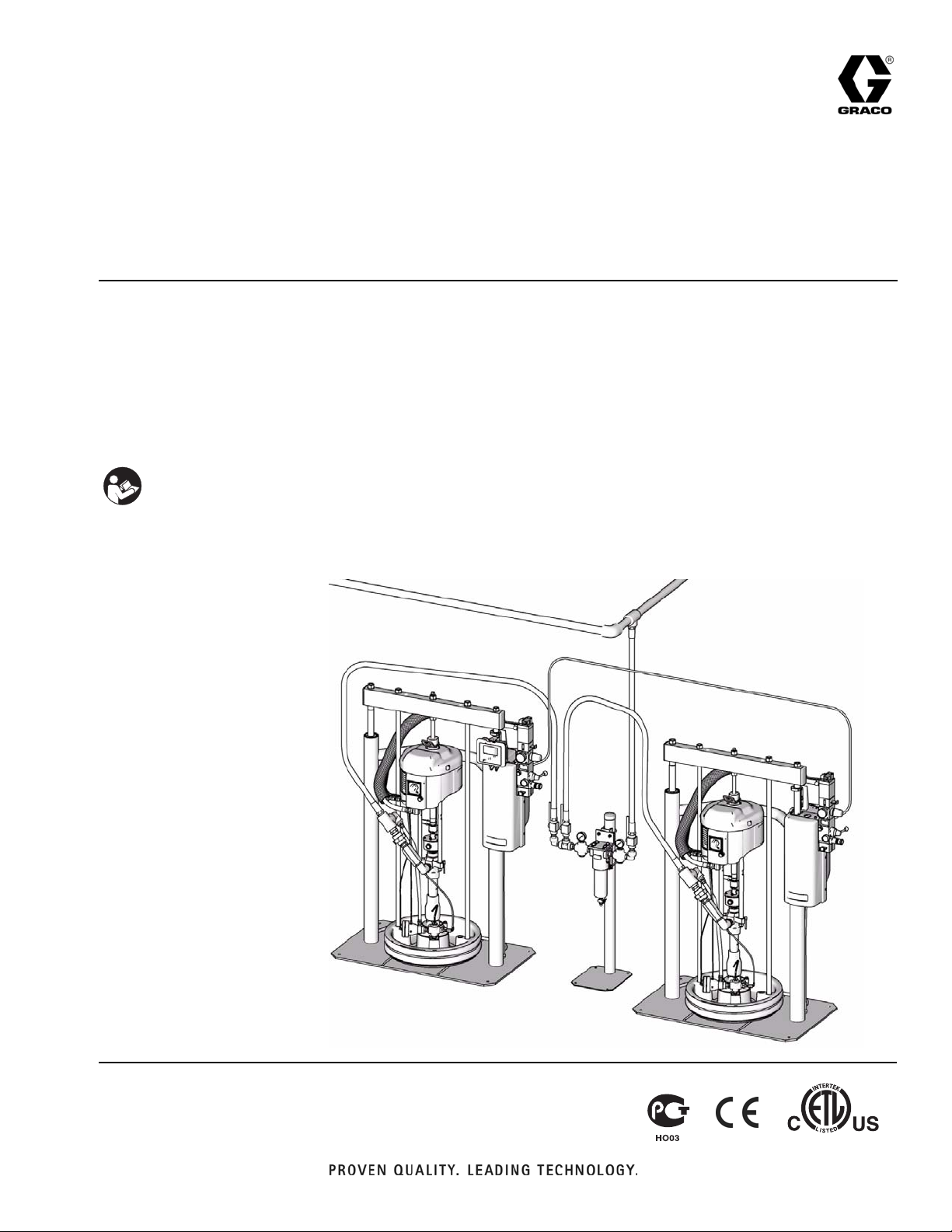
Tandem Supply
Systems
312395D
For use with non-heated bulk supply of medium to high viscosity sealants and adhesive
materials. Not for use in hazardous locations.
150 psi (1.0 MPa, 10 bar) Maximum Air Inlet Pressure - 3 in. rams
125 psi (0.9 MPa, 9 bar) Maximum Air Inlet Pressure - 6.5 in. rams
Important Safety Instructions
Read all warnings and instructions in this manual.
Save these instructions.
US Patent Pending
The Graco Control Architecture Electric Components are Listed in Intertek’s Directory of Listed Products.
TI10865A
2ECOGNIZED#OMPONENT
#-
#ERTIFIEDTO#!.#3!#3!#.O
#ONFORMSTO5,
Page 2

Contents
Related Manuals . . . . . . . . . . . . . . . . . . . . . . . . . . . 3
Translations . . . . . . . . . . . . . . . . . . . . . . . . . . . . . 3
Models . . . . . . . . . . . . . . . . . . . . . . . . . . . . . . . . . . . 4
Warnings . . . . . . . . . . . . . . . . . . . . . . . . . . . . . . . . . 7
Overview . . . . . . . . . . . . . . . . . . . . . . . . . . . . . . . . . . 9
System Description . . . . . . . . . . . . . . . . . . . . . . . 9
Ram Installation . . . . . . . . . . . . . . . . . . . . . . . . . 9
Fluid Filter Kit Installation . . . . . . . . . . . . . . . . . . 9
Grounding . . . . . . . . . . . . . . . . . . . . . . . . . . . . . . 9
Integrated Air Controls . . . . . . . . . . . . . . . . . . . 10
System Components (Pneumatic Crossover) . . 10
255468 Light Tower Accessory . . . . . . . . . . . . . 12
Communications Gateway Module . . . . . . . . . . 12
Module Status LED Signals . . . . . . . . . . . . . . . 12
System Components (Electronic Crossover) . . 13
Display Module (Electronic Crossover Systems) 15
Fluid Control Module . . . . . . . . . . . . . . . . . . . . . 18
Electronic Crossover Operation . . . . . . . . . . . . . . 19
Pressure Relief Procedure . . . . . . . . . . . . . . . . 19
Flush Before Using Equipment . . . . . . . . . . . . . 19
Startup . . . . . . . . . . . . . . . . . . . . . . . . . . . . . . . 19
Priming . . . . . . . . . . . . . . . . . . . . . . . . . . . . . . . 20
Automatic Crossover . . . . . . . . . . . . . . . . . . . . . 21
Manual Crossover . . . . . . . . . . . . . . . . . . . . . . . 21
Recirculate Function . . . . . . . . . . . . . . . . . . . . . 21
Depressurize Function . . . . . . . . . . . . . . . . . . . 22
Shutdown . . . . . . . . . . . . . . . . . . . . . . . . . . . . . 22
Setup Screens . . . . . . . . . . . . . . . . . . . . . . . . . . . . 23
Password Screen . . . . . . . . . . . . . . . . . . . . . . . . 23
Setup Screen 1 . . . . . . . . . . . . . . . . . . . . . . . . . 23
Maintenance Setup Screen 1 . . . . . . . . . . . . . . 24
Maintenance Setup Screen 2 . . . . . . . . . . . . . . 24
Hardware Setup Screen 1 . . . . . . . . . . . . . . . . . 25
Hardware Setup Screen 2 . . . . . . . . . . . . . . . . . 25
Hardware Setup Screen 3 . . . . . . . . . . . . . . . . . 25
Advanced Setup Screen 1 . . . . . . . . . . . . . . . . . 26
Advanced Setup Screen 2 . . . . . . . . . . . . . . . . . 26
Advanced Setup Screen 3 . . . . . . . . . . . . . . . . . 27
Advanced Setup Screen 4 . . . . . . . . . . . . . . . . . 27
Advanced Setup Screen 5 . . . . . . . . . . . . . . . . . 27
Run Screens . . . . . . . . . . . . . . . . . . . . . . . . . . . . . . 28
Home Run Screen . . . . . . . . . . . . . . . . . . . . . . . 28
Status Screens . . . . . . . . . . . . . . . . . . . . . . . . . 29
Maintenance Screens . . . . . . . . . . . . . . . . . . . . 30
Report Screens . . . . . . . . . . . . . . . . . . . . . . . . . 31
Fluid Filter Kit Dimensions . . . . . . . . . . . . . . . . . . 32
Technical Data . . . . . . . . . . . . . . . . . . . . . . . . . . . . 35
Graco Standard Warranty . . . . . . . . . . . . . . . . . . . 36
Graco Information . . . . . . . . . . . . . . . . . . . . . . . . . 36
2 312395D
Page 3

Related Manuals
Related Manuals
Component Manuals in U.S. English:
Manual Description
312400 Tandem Supply Systems Repair-Parts
312371 Supply Systems Operation
312373 Supply Systems Repair-Parts
®
Displacement Pumps
®
Pump Packages
™
Displacement Pumps (145cc,
312375
312376
311827
Check-Mate
Instructions-Parts
Check-Mate
Instruction-Parts
Dura-Flo
180cc, 220cc, 290cc) Instructions-Parts
Manual
311825
311717
311828
Dura-Flo
580cc) Instructions-Parts Manual
Carbon Steel Displacement Pump
(1000cc) Instructions-Parts Manual
Dura-Flo
180cc, 220cc, 290cc) Instructions-Parts
™
Displacement Pumps (430cc,
™
Pump Packages (145cc,
Manual
311826
311833
312467
312468
312469
312470
Dura-Flo
580cc) Instructions-Parts Manual
Two-Ball NXT
Instructions-Parts Manual
100 cc Check-Mate Displacement Pump
Repair Parts Manual
200 cc Check-Mate Displacement Pump
Repair Parts Manual
250 cc Check-Mate Displacement Pump
Repair Parts Manual
500 cc Check-Mate Displacement Pump
Repair Parts Manual
311238 NXT
308213 Premier
™
Pump Packages (430cc,
™
Pump Packages (1000cc)
™
Air Motor Instructions-Parts
®
Air Motor Instructions-Parts
312374 Air Controls Instructions-Parts
312491 Pump Fluid Purge Kit
Translations
The Tandem Supply System Operation manual is available in the following languages. See the following chart
for specific languages and corresponding part numbers.
Manual Language
312718 Chinese
312719 French
312720 German
312721 Japanese
312722 Korean
312723 Portuguese
312724 Spanish
313136 Italian
313162 Russian
312492 Drum Roller Kit Instruction
312493 Light Tower Kit Instruction
312864
313138
Communications Gateway Module,
Instructions-Parts
Supply System Communications Gateway
Module Installation Kit, Instructions-Parts
406681 Platen Cover Kit
312395D 3
Page 4
Models
Models
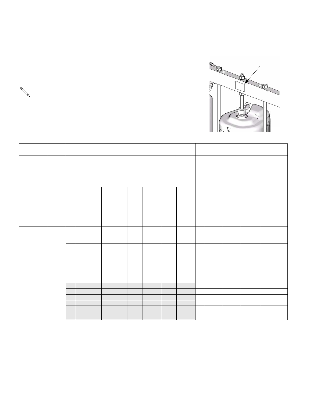
Check the identification plate (ID) for the 6-digit part number of your tandem system. Use the following matrix to define the construction of your system, based on
the six digits. For example, Tandem Part No. TC2414 represents a Check-Mate
tandem system (TC), pump (24), crossover option (1), and platen/ram option (4).
Systems with the TD as the first and second digits are Dura-Flo tandem systems.
Some configurations in the following matrix cannot be built. See the
Product Selection Guide for available systems.
ID
To order replacement parts, see Parts section in manual 312400. The digits in
the matrix do not correspond to the Ref. Nos. in the Parts drawings and lists.
TC 24 1 4
First and
Second
Digit
TC
(Tandem
System with
Check-Mate
displacement pump)
TD
(Tandem
System with
Dura-Flo
displacement pump)
Third
and
Fourth
Digit
Pump
Code
(See
Table 2
for
2-digit
Check-
Mate
pump
code)
(See
Table 3
for
2-digit
Dura-
Flo
pump
code)
Fifth Digit
1
2
3
4
5
6
7
8
Electronic
Crossover
(Smart
Motors
only)
✔✔✔
✔✔✔
✔✔
✔✔
✔✔
✔
Pneumatic
Crossover
(Standard
Fifth Digit Sixth Digit
Crossover Options Platen/Ram Options
Depressurize/
Recirculate
Valve
Motors
only)
✔
✔
Fluid
Filter
Carbon
Steel SST
Ram
Size
n/a 4 30 G D EPDM D200, 0V
n/a A 55 G P EPDM D200, 0V
n/a B 55 G P EPDM D200, Vac
n/a C 55 G P EPDM D200, Vdc
n/a F 55 G P EPDM D200S, 0V
n/a G 55 G P EPDM D200S, Vac
D200,
(3 in.)
D200S,
(6.5 in.)
Platen
Size
Sixth Digit
H 55 G P EPDM D200S, Vdc
J 55 G N EPDM D200, 0V
L 55 G N EPDM D200, Vac
M 55 G N EPDM D200, Vdc
R 55 G N EPDM D200S, 0V
S 55 G N EPDM D200S, Vac
T 55 G N EPDM D200S, Vdc
Platen
Style
(see
Key
below)
Wiper
Material
TI11157A
Ram Code
(See Table
1, page 5)
Platen Style Key:
D = 90° D Style
N = Non-PTFE
P = PTFE
T = Tire Style
4 312395D
Page 5

Models
Table 1: Ram Identification Code
Ram Options (see manual 312373 for parts)
Size Style Volt Air Controls
D200, 0V 3 in. DP no volt INT
D200S, 0V 6.5 in. DP no volt INT
D200, Vdc 3 in. DP 24 Vdc INT
D200, Vac 3 in. DP 100-240
Vac
D200S, Vdc 6.5 in. DP 24 Vdc INT
D200S, Vac 6.5 in. DP 100-240
Vac
Key:
DP = Dual Post Ram
INT = Integrated Air Controls
INT
INT
Table 2: Check-Mate Pump Identification
Code/Part No. Index
Pump Part No.
Pump
Code
(see manual
312376)
NXT 2200/CM 100
11 P40LCS
12 P40LCM
13 P40RCS
14 P40RCM
NXT 3400/CM 100
15 P63LCS
16 P63LCM
17 P63RCS
18 P63RCM
NXT 2200/CM 200
21 P23LCS
22 P23LCM
23 P23RCS
24 P23RCM
25 P23LSS
26 P23LSM
27 P23RSS
28 P23RSM
NXT 3400/CM 200
29 P36LCS
2A P36LCM
Pump
Code
NXT 6500/CM 200
NXT 6500/CM 500
Premier/CM 250
Premier/CM 500
Pump Part No.
2L P68LCS
2M P68LCM
2R P68RCS
2S P68RCM
59 P26LCS
5A P26LCM
5B P26RCS
5C P26RCM
5F P26LSS
5G P26LSM
5H P26RSS
5J P26RSM
3L P82LCS
3M P82LCM
5L P39LCS
5M P39LCM
5R P39LSS
5S P39LSM
2B P36RCS
2C P36RCM
2F P36LSS
2G P36LSM
2H P36RSS
2J P36RSM
(see manual
312376)
312395D 5
Page 6

Models
Table 3: Dura-Flo Pump Identification Code/Part No. Index
Pump Part No.
Pump
Code
(see manual
311828)
NXT 2200/DF 145SS
A1 P31LSS
A2 P31LSM
A3 P31HSS
A4 P31HSM
NXT 3400/DF 145SS
11 P46LSS
12 P46LSM
13 P46HSS
14 P46HSM
NXT 3400/DF 180SS
15 P40LSS
16 P40LSM
17 P40HSS
18 P40HSM
NXT 3400/DF 220SS
21 P30LSS
22 P30LSM
23 P30HSS
24 P30HSM
NXT 6500/DF 220SS
2A P57LSS
2B P57LSM
2C P57HSS
2D P57HSM
NXT 6500/DF 290SS
31 P45LSS
32 P45LSM
33 P45HSS
34 P45HSM
Premier/DF 290SS
3L P67LSS
3M P67LSM
3R P67HSS
3S P67HSM
Pump Part No.
Pump
Code
(see manual
311826)
NXT 3400/DF 430CS
41 P15LCS
42 P15LCM
43 P15HCS
44 P15HCM
NXT 3400/DF 430SS
45 P15LSS
46 P15LSM
47 P15HSS
48 P15HSM
NXT 6500/DF 430CS
49 P32LCS
4A P32LCM
4B P32HCS
4C P32HCM
NXT 6500/DF 430SS
4F P32LSS
4G P32LSM
4H P32HSS
4J P32HSM
Premier/DF 430
4L P44LSS
4M P44LSM
4R P44LCS
4S P44LCM
NXT 3400/DF 580CS
51 P12LCS
52 P12LCM
53 P12HCS
54 P12HCM
NXT 3400/DF 580SS
55 P12LSS
56 P12LSM
57 P12HSS
58 P12HSM
Pump Part No.
Pump
Code
(see manual
311826)
NXT 6500/DF 580CS
59 P22LCS
5A P22LCM
5B P22HCS
5C P22HCM
NXT 6500/DF 580SS
5F P22LSS
5G P22LSM
5H P22HSS
5J P22HSM
Premier/DF 580CS
5L P34LSS
5M P34LSM
5R P34LCS
5S P34LCM
Pump Part No.
Pump
Code
(see manual
311833)
NXT 3400/DF 1000CS
O1 P06LCS
O2 P06LCM
O3 P06HCS
O4 P06HCM
NXT 3400/DF 1000SS
O5 P06LSS
O6 P06LSM
O7 P06HSS
O8 P06HSM
NXT 6500/DF 1000CS
O9 P10LCS
0A P10LCM
0B P10HCS
0C P10HCM
NXT 6500/DF 1000SS
0F P10LSS
0G P10LSM
0H P10HSS
0J P10HSM
Premier/DF 1000
0L NR
0M NR
0R NR
0S NR
6 312395D
Page 7
Warnings
Warnings
The following warnings are for the setup, use, grounding, maintenance, and repair of this equipment. The exclamation point symbol alerts you to a general warning and the hazard symbol refers to procedure-specific risk. Refer back
to these warnings. Additional, product-specific warnings may be found throughout the body of this manual where
applicable.
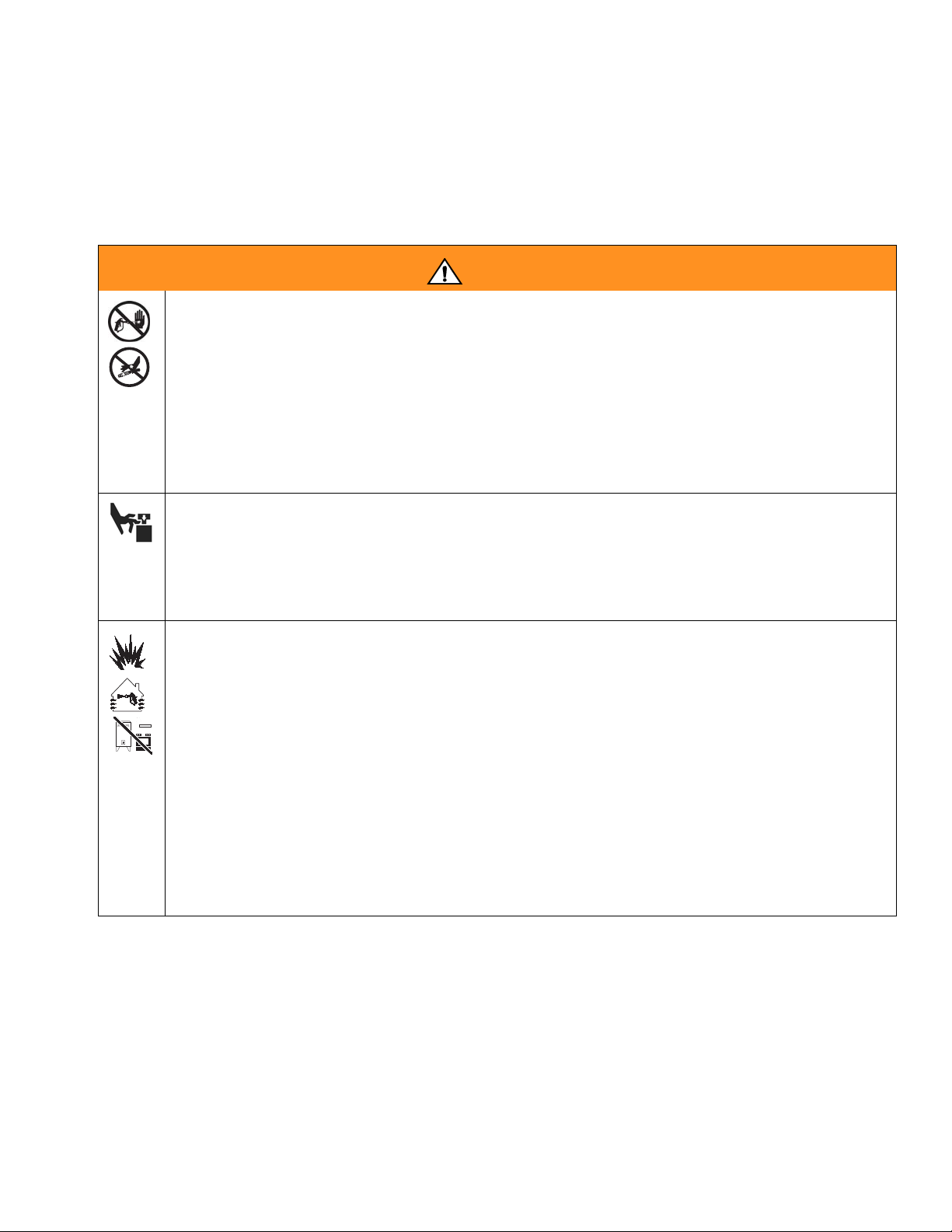
WARNING
SKIN INJECTION HAZARD
High-pressure fluid from gun, hose leaks, or ruptured components will pierce skin. This may look like just
a cut, but it is a serious injury that can result in amputation. Get immediate surgical treatment.
• Do not point gun at anyone or at any part of the body.
• Do not put your hand over the spray tip.
• Do not stop or deflect leaks with your hand, body, glove, or rag.
• Do not spray without tip guard and trigger guard installed.
• Engage trigger lock when not spraying.
• Follow Pressure Relief Procedure in this manual, when you stop spraying and before cleaning,
checking, or servicing equipment.
MOVING PARTS HAZARD
Moving parts can pinch or amputate fingers and other body parts.
• Keep clear of moving parts.
• Do not operate equipment with protective guards or covers removed.
• Pressurized equipment can start without warning. Before checking, moving, or servicing equipment,
follow the Pressure Relief Procedure in this manual. Disconnect power or air supply.
FIRE AND EXPLOSION HAZARD
Flammable fumes, such as solvent and paint fumes, in work area can ignite or explode. To help prevent
fire and explosion:
• Use equipment only in well ventilated area.
• Eliminate all ignition sources; such as pilot lights, cigarettes, portable electric lamps, and plastic drop
cloths (potential static arc).
• Keep work area free of debris, including solvent, rags and gasoline.
• Do not plug or unplug power cords, or turn power or light switches on or off when flammable fumes
are present.
• Ground all equipment in the work area. See Grounding instructions.
• Use only grounded hoses.
• Hold gun firmly to side of grounded pail when triggering into pail.
• If there is static sparking or you feel a shock, stop operation immediately. Do not use equipment
until you identify and correct the problem.
• Keep a working fire extinguisher in the work area.
312395D 7
Page 8
Warnings
WARNING
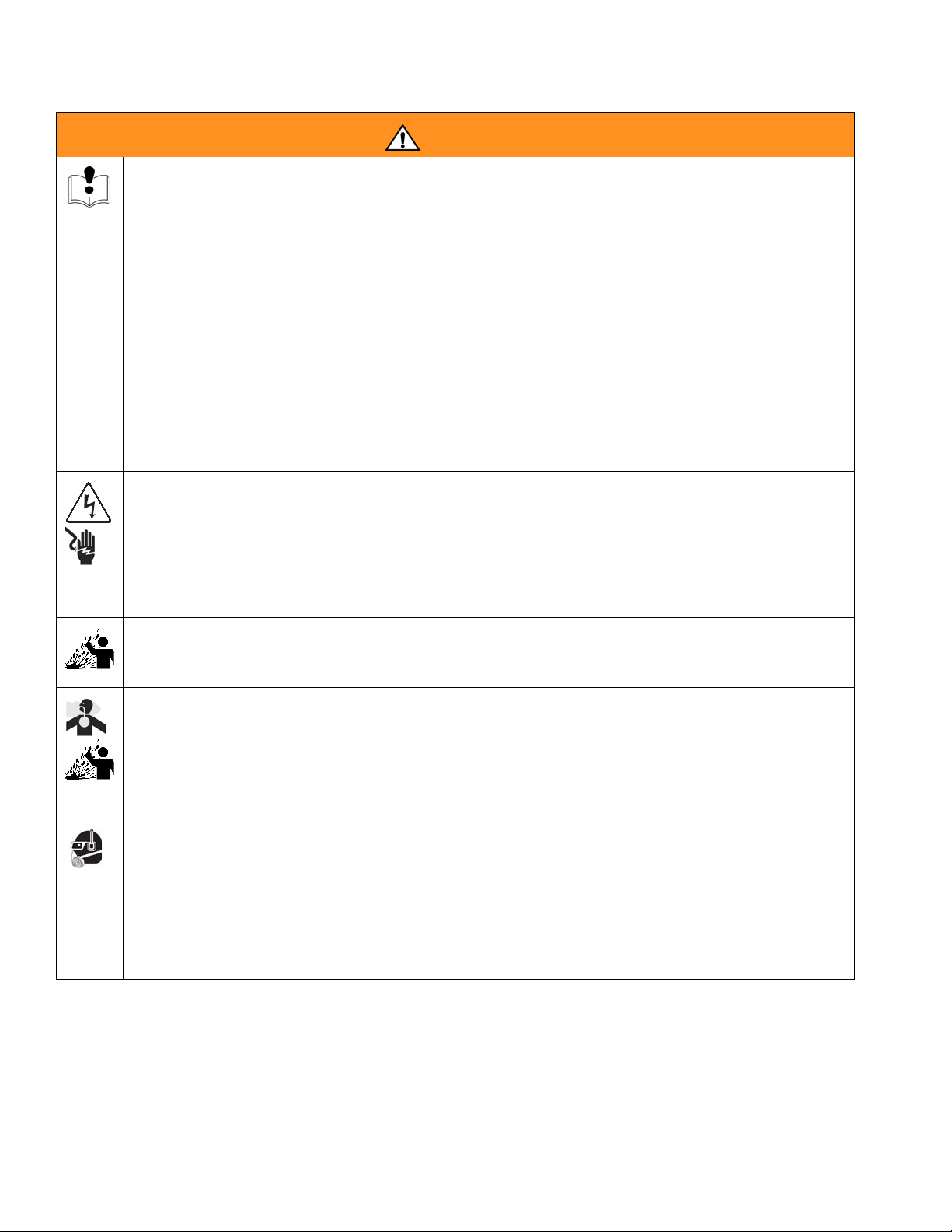
EQUIPMENT MISUSE HAZARD
Misuse can cause death or serious injury.
• Do not operate the unit when fatigued or under the influence of drugs or alcohol.
• Do not exceed the maximum working pressure or temperature rating of the lowest rated system
component. See Technical Data in all equipment manuals.
• Use fluids and solvents that are compatible with equipment wetted parts. See Technical Data in all
equipment manuals. Read fluid and solvent manufacturer’s warnings. For complete information
about your material, request MSDS forms from distributor or retailer.
• Check equipment daily. Repair or replace worn or damaged parts immediately with genuine manufacturer’s replacement parts only.
• Do not alter or modify equipment.
• Use equipment only for its intended purpose. Call your distributor for information.
• Route hoses and cables away from traffic areas, sharp edges, moving parts, and hot surfaces.
• Do not kink or over bend hoses or use hoses to pull equipment.
• Keep children and animals away from work area.
• Comply with all applicable safety regulations.
ELECTRIC SHOCK HAZARD
Improper grounding, setup, or usage of the system can cause electric shock.
• Turn off and disconnect power cord before servicing equipment.
• Use only grounded electrical outlets.
• Use only 3-wire extension cords.
• Ensure ground prongs are intact on sprayer and extension cords.
• Do not expose to rain. Store indoors.
SPLATTER HAZARD
During blowoff of platen splatter may occur.
• Use minimum drum removal air pressure.
TOXIC FLUID OR FUMES HAZARD
Toxic fluids or fumes can cause serious injury or death if splashed in the eyes or on skin, inhaled, or
swallowed.
• Read MSDS’s to know the specific hazards of the fluids you are using.
• Store hazardous fluid in approved containers, and dispose of it according to applicable guidelines.
• Always wear impervious gloves when spraying or cleaning equipment.
PERSONAL PROTECTIVE EQUIPMENT
You must wear appropriate protective equipment when operating, servicing, or when in the operating
area of the equipment to help protect you from serious injury, including eye injury, inhalation of toxic
fumes, burns, and hearing loss. This equipment includes but is not limited to:
• Protective eyewear
• Clothing and respirator as recommended by the fluid and solvent manufacturer
•Gloves
• Hearing protection
8 312395D
Page 9
Overview
Overview
System Description
Each tandem supply system consists of two air-powered
rams. Each ram drives a Check-Mate pump and a platen
into a drum of material. The pump removes material
from the drum and pushes it through a supply hose to a
customer-supplied header. Material flows through the
header to individual dispense drops.
When one drum is emptied the system performs an
automatic crossover, shutting off the air supply to the
pump on the empty ram and activating the pump on the
full ram.
Keep clear of the inactive ram, as automatic crossover
may occur unexpectedly. To repair or adjust the ram,
first follow all steps of the Pressure Relief Procedure
on page 19.
Ram Installation
Install the rams as explained in manual 312371, supplied. See also F
over systems) and F
crossover systems).
IG. 2 on page 11 (for pneumatic cross-
IG. 3 on page 14 (for electronic
Grounding
The equipment must be grounded. Grounding reduces
the risk of static and electric shock by providing an
escape wire for the electrical current due to static build
up or in the event of a short circuit.
Pump: use ground wire and clamp (supplied). Loosen
grounding lug locknut and washer. Insert ground wire
end into lug slot and tighten locknut securely. Connect
ground clamp to a true earth ground.
Air and fluid hoses: use only electrically conductive
hoses with a maximum of 500 ft. (150 m) combined
hose length to ensure grounding continuity. Check electrical resistance of hoses. If total resistance to ground
exceeds 29 megohms, replace hose immediately.
Air compressor: follow manufacturer’s recommendations.
Dispense valve: ground through connection to a prop-
erly grounded fluid hose and pump.
Fluid supply container: follow local code.
Fluid Filter Kit Installation
Solvent pails used when flushing: follow local code.
Some systems include a fluid filter kit. See Fluid Filter
Kit Dimensions on page 32. Ensure that the fluid filter
stand base is level in all directions. If necessary, level
the base using metal shims. Secure the base to the floor
using anchors that are long enough to prevent the filter
stand from tipping.
312395D 9
Use only conductive metal pails, placed on a grounded
surface. Do not place the pail on a nonconductive sur-
face, such as paper or cardboard, which interrupts
grounding continuity.
To maintain grounding continuity when flushing or
relieving pressure: hold metal part of the dispense
valve firmly to the side of a grounded metal pail, then
trigger the valve.
Page 10
Overview
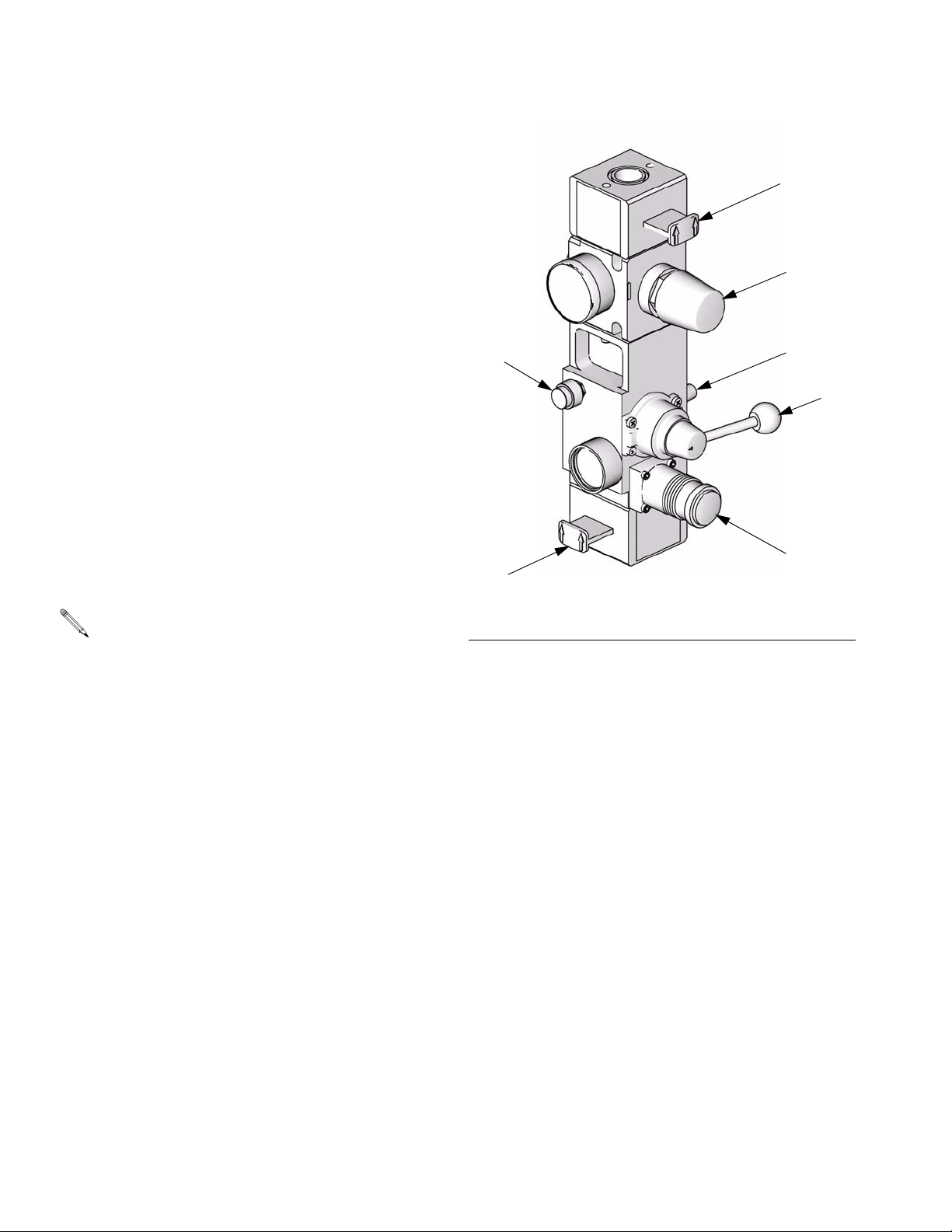
Integrated Air Controls
The integrated air controls include:
• Main air slider valve (BA): turns air on and off to
the system. When closed, the valve relieves pressure downstream.
BF
• Ram air regulator (BB): controls ram up and down
pressure and blowoff pressure.
• Ram director valve (BC): controls ram direction.
• Exhaust port with muffler (BD)
• Air motor regulator (BE): controls air pressure to
motor.
• Air motor slider valve (BF): turns air on and off to
the air motor. When closed, the valve relieves air
trapped between it and the air motor. Push the valve
in to shutoff.
• Blowoff button (BG): turns air on and off to push
the platen out of an empty drum.
The air solenoid (Y, FIG. 3), the air motor slider
valve (BF), and the main air slider valve (BA) must
be open for air to flow to the air motor.
• Air relief valve (not visible, attached to ram air reg-
ulator): automatically relieves excessive pressure to
the pump.
BE
BG
BA
F
IG. 1. Integrated Air Controls
BD
BC
BB
TI10438A
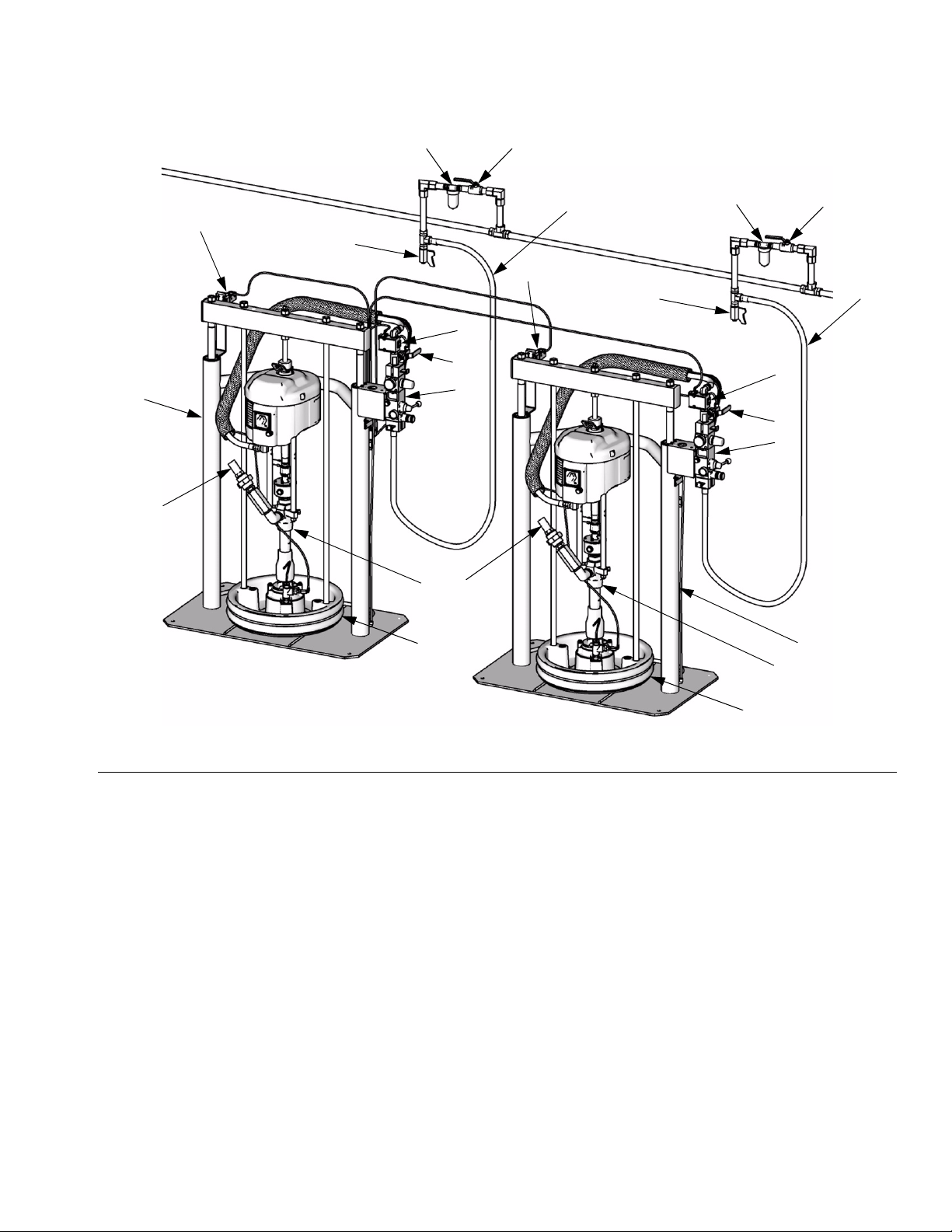
System Components (Pneumatic Crossover)
FIG. 2. shows a pneumatic crossover system. Refer to
manual 312371 (supplied) for ram installation and operating instructions. The pneumatic crossover operates as
follows:
During system operation, as the ram approaches the
drum bottom, the top of the ram contacts the limit switch
(E). The limit switch shuts off air to the air motor via a
solenoid valve (Y), which stops air flow to one motor and
starts air flow to the other air motor. This allows continuous material flow and changing of material drums.
The position of the limit switch (E) on the ram determines when the air motor is turned off. Start by positioning the limit switch to trip when the ram platen (D) is 1 in.
(25 mm) from the bottom of the drum. During operation
the position may be adjusted as desired.
The bypass valve (L) allows you to prime the inactive
pump after a drum change. Open the valve to prime the
pump. Close the valve when priming is complete, and
during normal operation.
10 312395D
Page 11
Overview
V
W
T
V
W
E
U
E
U
T
Y
L
A
H
Y
L
H
S
S
C
D
FIG. 2: Component Identification, Pneumatic Crossover
Key to FIG. 2:
ARam A
BRam B
C Pump (Ram A and B)
D Platen (Ram A and B)
E Limit Switch (Ram A and B)
H Integrated Air Controls (Ram A and B); see page 10
L Bypass Valve (Ram A and B)
S Fluid Line (not supplied)
T Main Air Line (not supplied)
U Air Line Drain Valve (not supplied)
V Air Filter (not supplied)
W Bleed-Type Air Shutoff Valve (not supplied)
Y Solenoid Valve (Ram A and B)
B
C
D
TI11160A
312395D 11
Page 12

Overview
255468 Light Tower Accessory
Order the 255468 Light Tower Accessory as a diagnostic indicator for tandem supply systems. Refer to Light
Tower Kit manual for installation instructions. See Table
4 for a description of light tower signals.
Table 4: Light Tower Signals
Signal Description
Green on only System is powered up and there
are no error conditions present.
Yellow flashing A low priority error exists.
Yellow on A medium priority error exists.
Red flashing A high priority error exists.
Red on The system is shut down due to
error conditions.
Communications Gateway Module
The Communications Gateway Module (CGM) provides
a control link between Graco Control Architecture based
systems and a selected fieldbus. This provides the
means for remote monitoring and control by external
automation systems.
Data provided by the CGM to the fieldbus depends on
which Graco Control Architecture based system and
fieldbus are connected. A data map supplied on a map
token is defined for this pairing. Once the data map has
been loaded into the CGM, it is stored internally, and the
map token is no longer required for operation.
Module Status LED Signals
Signal Description
Green on System is powered up
Yellow Internal communication in progress
Red
Solid
*Red
(5 flashes)
*Red
(7 flashes)
*The red LED (F) will flash a code, pause, then repeat.
See for diagnositc information in CGM manual 312864.
NOTE:
Verify that you are using the correct token for your system and reinstall token. If fails, order new token.
CGM hardware failure
CGM hardware failure
Data map load failure
Incorrect data map for fieldbus type
No data map loaded
12 312395D
Page 13

Overview
System Components (Electronic Crossover)
See FIG. 3. Before you install the system, you should be
familiar with the following components.
Reference numbers and letters in parentheses in
the text refer to the callouts in the figures.
Both rams (A and B) include a Check-Mate Pump (C),
platen (D), integrated air controls (H), drum empty sensor (E), and fluid control module (G).
Only Ram A includes the display module (F) and power
supply box (K).
• Drum empty sensor (E). Signals drum empty condition.
• Display module (F). Mounted on Ram A only. Provides Run Mode status screens, Setup screens, and
control keys.
• Fluid control module (G). See page 18.
• Integrated air controls (H). See page 10.
• Power supply box (K).
• Air motor solenoid (Y). Solenoid is on when system
is on and in Run Mode, Recirculate Mode, or Prime
Mode. Solenoid is off when system is shut off or
when in Depressurize Mode, or the ram is in an
Inactive Ready Mode. Turns on in Recirculate Mode.
The solenoid LED will illuminate when the solenoid
is on.
• Depressurize/recirculate fluid valve (Z). Depressurizes system when Depressurize Mode is active.
Recirculates fluid when Recirculate Mode is active.
To depressurize the system, press the Depressurize
key on the display module and select Yes when
asked if you want to depressurize the system. Follow
the Pressure Relief Procedure on page 19. Shutting
off power or removing power from the system will not
depressurize the system.
312395D 13
Page 14

Overview
A
F
E
Y
B
E
X
H
Y
H
G
G
K
C
Z
DZ
J
D
TI10865A
FIG. 3: Component Identification, Electronic Crossover
Key to FIG. 3:
ARam A
BRam B
C Pump (Ram A and B)
D Platen (Ram A and B)
E Drum Empty Sensor (partially hidden; Ram A and B)
F Display Module (Ram A only)
G Fluid Control Module (behind rear shroud, Ram A and B)
H Integrated Air Controls (Ram A and B); see page 10
J Fluid Filter and Stand
K Power Supply Box (behind shroud, Ram A only)
X CAN Communication Cable
Y Air Motor Solenoid (Ram A and B)
Z Depressurize/Recirculate Fluid Valve (Ram A and B)
C
14 312395D
Page 15

Display Module (Electronic Crossover Systems)
FIG. 4: Display Module (see Table 5 for Module Key Functions)
Overview
Table 5: Display Module Key Functions (see FIG. 4)
Key Function
System On/Off Press to toggle the system ON and OFF.
• When ON, the active ram is pressurized and the air motor solenoid is ON. The active ram
is indicated by a highlighted letter (A or B) on the display. The hose graphic is darkened on
the active ram when the system is ON.
• When OFF, the air motor solenoids are OFF.
CAUTION: Turning the system OFF relieves pressure from the pump motor. It does not
depressurize the fluid pressure. Follow the Pressure Relief Procedure, page 19.
NOTE: The ram up/down and blowoff air is independent of the electronic controls and can be
operated anytime the main air slider valve is open and air pressure is available.
Cancel Cancels current action or window.
Setup Press to enter Setup Mode, or to exit Setup Mode and return to the Run screens.
• Setup changes can be made while system is operating.
• Password is required if enabled.
Enter Opens drop down menus on Setup fields.
Press to enter changes and to select an action.
Arrows Left/Right Use to move between tabs in a screen or to highlight digits.
Arrows Up/Down Use to increase or decrease a value, and move between screens or between fields.
312395D 15
Page 16

Overview
Table 5: Display Module Key Functions (see F
IG. 4)
Key Function
Depressurize Use to relieve fluid pressure from the pump outlet to below the platen on the currently active
ram. This function is not available with all models; see page 4.
If system is pressurized, press key.
• Display reads “Depressurize system?”
• Select Yes or No. Key LED turns on in Depressurize Mode. Depressurizing the active
ram will depressurize both rams.
NOTE: If additional user-supplied check valves have been added to the system, only the active
ram will be depressurized. You must do a manual crossover and select depressurize again to
depressurize both rams. See Crossover section of this table on page 17.
If system is depressurized, press key.
• Display reads “Pressurize system?”
• Select Yes or No. Key LED turns off in Pressurize Mode.
Pump Prime • Activates the air solenoid on the inactive ram, allowing you to purge air and prime the
pump.
• Clears the Pump Not Primed warning or alarm (depending on setup selection).
• Resets the drum volume remaining to the drum fill volume setpoint.
Press key when in Run Mode.
• Display reads “Prime the inactive ram?”
• Select Yes to prime. Key LED turns on. One minute before expiration of the prime time
counter the LED begins to blink. Key LED turns off when counter expires.
Press key when in Prime Mode to exit Prime Mode or to reset counter to the prime time.
• Display reads “Exit Prime Mode?”
• Select Yes to exit Prime Mode. Key LED turns on. One minute before expiration of the
prime time counter the LED begins to blink. Key LED turns off when counter expires.
• Select No. Display reads “Reset the Prime Time Counter?” Select Yes to reset. Select No
to not reset.
Recirculate Recirculate Mode pumps fluid from the drum, through the pump, and back into the drum on the
currently active ram. This function is not available with all models; see page 4.
Set motor air regulator to 30 psi (0.2 MPa, 2.1 bar) before pressing Recirculate key.
If system is not in Recirculate Mode, press key.
• Display reads “Turn recirculation on?”
• Select Yes or No. Key LED turns on in Recirculate Mode. Adjust motor air regulator to
obtain desired flow rate.
If system is in Recirculate Mode, press key.
• Display reads “Turn recirculation off?”
• Select Yes or No. Key LED turns off upon exiting Recirculate Mode.
16 312395D
Page 17

Overview
Table 5: Display Module Key Functions (see F
IG. 4)
Key Function
Crossover Crossover key transitions the active ram to inactive, and inactive ram to active.
NOTE: If an alarm is present on the inactive ram, crossover will not be successful. Manual
crossover is disabled in single ram operation.
Press key.
• Display reads “Initiate a crossover?”
• Select Yes or No.
If Crossover error exists, press key to clear Crossover error.
• Display reads “Clear crossover alarm?”
• Select Yes or No.
312395D 17
Page 18

Overview
Fluid Control Module
Table 6: Fluid Control Module Sensor Connections
Connection Ram Sensor Description
1 not used not used
2 not used not used
3 Ram A Fluid pressure at filter inlet.
4 Ram A Fluid pressure at filter outlet.
5 Ram A and Ram B Signal harness: air motor solenoid (white), light tower (green),
drum low (yellow), drum empty (black)
6 Ram A and Ram B Fluid depressurize/recirculate solenoid.
7 Ram A and Ram B Air motor sensors.
CAN communication
cable 1
CAN communication
cable 2
Ram A (F
IG. 5, top view) From Ram A Fluid Control Module to Display Module.
Ram A and B (F
bottom view)
IG. 5,
15 ft (4.57 m) from Ram A Fluid Control Module to Ram B Fluid
Control Module.
Ram A, Top View Ram B, Top View
CAN Cable 1
3
45
TI10866A TI10867A
5
Bottom View, Both Rams
CAN Cable 2
TI10868A
67
FIG. 5: Fluid Control Module Sensor Connections
18 312395D
Page 19

Electronic Crossover Operation
Electronic Crossover Operation
These instructions are for the display module functions used on tandem systems. For basic ram and
pump operation, refer to the component manuals
supplied.
Pressure Relief Procedure
1. Lock the gun/valve trigger.
2. Press the System On/Off key . If system is
On, display will read: “Turn the system off?” Select
Yes to turn off. See F
IG. 6.
If you suspect that the spray tip/nozzle or hose is completely clogged, or that pressure has not been fully
relieved after following the steps above, very slowly
loosen the tip guard retaining nut or hose end coupling
and relieve pressure gradually, then loosen completely.
Now clear the tip/nozzle or hose.
Flush Before Using Equipment
The pump was tested with lightweight oil, which is left in
the fluid passages to protect parts. To avoid contaminating your fluid with oil, flush the pump with a compatible
solvent before use. See your pump manual for flushing
directions.
Startup
1. On both ram A and B, turn on the main air slider
valve (BA). Set the ram director valve (BC) to the
down position. The ram will slowly drop.
2. Turn on the air motor slider valve (BF) on both ram A
and B.
FIG. 6: System Function Screen
3. Turn off the air motor slider valve (BF) on both ram A
and B.
4. On both ram A and B, turn off the main air slider
valve (BA). Set the ram director valve (BC) to the
down position. The ram will slowly drop.
5. Unlock the gun/valve trigger.
6. Hold a metal part of the gun/valve firmly to the side
of a grounded metal pail, and trigger the gun/valve
to relieve pressure.
7. Lock the gun/valve trigger.
8. On both ram A and B, open the drain valve and/or
the pump bleed port. Have a container ready to
catch the drainage.
9. Leave the pump bleed port open until you are ready
to dispense again.
BF
BE
BC
BA
BB
TI10438A
FIG. 7. Integrated Air Controls
312395D 19
Page 20

Electronic Crossover Operation
3. Turn on the power on/off switch at the back of the
power supply box on ram A. The Splash screen will
appear. See F
IG. 8: Splash Screen
F
IG. 8.
4. Verify that “No Active Error” displays in the lower left
corner of the screen. If an error is displayed, refer to
the Troubleshooting section of manual 312400.
5. Press the System On/Off key . If system is
Off, display will read: “Turn the system on?” Select
Yes to turn on.
6. See F
IG. 9. The Home Run screen displays which
ram (A or B) is active and how much volume is
remaining in each drum. The fluid line is shown filled
indicating the system is on.
7. The air motor solenoid LED will illuminate.
2. Press the Pump Prime key . The display
prompts the operator to confirm. See F
IG. 10. Select
Yes to begin prime.
F
IG. 10: Prime Function Screen
3. The LED on the keypad will turn on. When the prime
timer is less than 1 minute, the LED will begin flashing. When the timer expires the LED and the air
motor solenoid will turn off.
4. To exit Prime Mode before the timer expires, press
the Pump Prime key . The display prompts the
operator to confirm. See F
IG. 11. Select Yes to exit
prime.
To extend the prime time counter, select No in F
IG.
11. Display will read “Reset the Prime Time Counter?” See F
IG. 12. Select Yes to reset.
Active ram is
highlighted
Fluid line shown filled
when system is ON
Current
screen
IG. 9: Home Run Screen
F
Priming
1. To prime the inactive ram, first ensure that the sys-
tem is on and in Run Mode; see Startup, page 19.
F
IG. 11: Exit Prime Mode Screen
F
IG. 12: Reset Prime Time Counter
20 312395D
Page 21

Electronic Crossover Operation
Automatic Crossover
Keep clear of the inactive ram, as automatic crossover
may occur unexpectedly. To repair or adjust the ram,
first follow all steps of the Pressure Relief Procedure
on page 19.
The automatic crossover feature allows continuous flow
and prevents system shutdown. If the active ram
encounters a pump runaway, drum empty, or air solenoid disconnected alarm it will attempt an automatic
crossover to the inactive ram.
The system will generate a crossover error if the active
ram attempts an automatic crossover while the inactive
ram has a pump runaway, drum empty, air solenoid disconnected, or not primed alarm.
Manual Crossover
If the active ram has a pump runaway error, drum
empty error, or air motor solenoid disconnected
error, the system will attempt an automatic crossover.
F
IG. 13: Crossover Function Screen
Recirculate Function
Use Recirculate Mode to pump fluid from the drum,
through the pump, and back into the drum on the currently active ram.
To enter Recirculate Mode, set motor air regulator to 30
In Run Mode, press the Crossover key . The dis-
play prompts the operator to confirm. See F
Press the Crossover key to initiate a manual crossover
to the inactive ram, provided the following conditions are
met:
• inactive ram is not in the drum empty error condition.
• air motor solenoid disconnected error does not
exist.
• pump runaway and not primed alarms do not exist.
IG. 13.
psi (0.2 MPa, 2.1 bar). Press the Recirculate key .
The display prompts the operator to confirm. Adjust
motor air regulator to obtain desired flow rate. See F
14.
To exit Recirculate Mode, press the Recirculate key. The
display prompts the operator to confirm.
You must exit Recirculate Mode before depressurizing or initiating a crossover.
While in Recirculate Mode, the inactive ram cannot
be primed.
IG.
F
IG. 14: Enter Recirculate Mode
312395D 21
Page 22

Electronic Crossover Operation
Depressurize Function
Use the Depressurize function to relieve fluid pressure
from the pump outlet to below the platen on the currently
active ram.
In Run Mode, press the Depressurize key . The
display prompts the operator to confirm depressurize or
pressurize (depending on current system status). See
F
IG. 15.
F
IG. 15: Depressurize Function Screen
Shutdown
CAUTION
Turning the system OFF relieves pressure from the
pump motor. It does not depressurize the fluid pressure. Follow the Pressure Relief Procedure, page
19.
The ram up/down and blowoff air is independent of
the electronic controls and can be operated anytime the main air slider valve is open and air pressure is available.
Follow the Pressure Relief Procedure, page 19.
22 312395D
Page 23

Setup Screens
Setup Screens
Password Screen
In Run Mode, press the Setup key . If the password
is not set to 0000, the Password screen will appear. See
F
IG. 16. Enter the password to continue in Setup Mode.
To set the password, see Advanced Setup Screen
4, page 27.
F
IG. 16: Password Screen
Setup Screen 1
Table 7: System Setup Parameters
Parameter Units Range
Operating Mode Tandem/Ram
A/Ram B
Not Primed
Event
Prime Time Minutes 1 - 9
Pump Runaway
Limit
Warning/Alarm Select as desired
Cycles per Minute
Select as desired
0 - 99 (Default is
60; 00 disables)
This screen allows you to change system setup parame-
ters. Use the Enter key to access pull-down
menus. See F
IG. 17: Setup Screen 1
F
IG. 17 and Table 7.
312395D 23
Page 24

Setup Screens
Maintenance Setup Screen 1
This screen allows you to change system maintenance
intervals. See F
F
IG. 18: Maintenance Setup Screen 1 FIG. 19: Maintenance Setup Screen 2
IG. 18 and Table 8.
Maintenance Setup Screen 2
This screen allows you to change platen seal maintenance intervals. See F
Table 8: Maintenance Setup Parameters
Parameter Units Range
Ram Maintenance (A and B)
Rebuild Pump (A
and B)
Rebuild Air Motor
(A and B)
Rebuild Platen
Seals (A and B)
IG. 19 and Table 8.
User Settable;
see Advanced
Setup Screen 1,
page 26
User Settable;
see Advanced
Setup Screen 1,
page 26
User Settable;
see Advanced
Setup Screen 1,
page 26
Drums 0 - 9999
0 - 999
(0 disables)
0 - 999
(0 disables)
0 - 99999
(0 disables)
(0 disables)
24 312395D
Page 25

Setup Screens
Hardware Setup Screen 1
This screen allows you to specify if a fluid filter monitor
is installed, and set the high and low limits for the pressure drop across the filter. See F
see Status Screen 2, page 29, for additional details.
Monitor the filter pressure readings through the normal
range of flow with a clean filter to establish the initial limit
settings.
Set the low limit to detect a filter element collapse
or a missing element.
Set the high limit to detect a clogged filter.
IG. 20 and Table 9. Also
Hardware Setup Screen 2
This screen allows you to specify if a fluid solenoid is
installed. The fluid solenoid controls the depressurize/recirculate valve. See F
FIG. 21: Hardware Setup Screen 2
IG. 21.
Hardware Setup Screen 3
This screen allows you to specify if a drum low sensor is
installed. See F
IG. 22.
F
IG. 20: Hardware Setup Screen 1
Table 9: Fluid Filter Monitor Setup Parameters
Parameter Units Range
Filter Mode Disabled Moni-
tor warning
Filter Monitor
Low Limit
Filter Monitor
High Limit
User Settable;
see Advanced
Setup Screen 1,
page 26
User Settable;
see Advanced
Setup Screen 1,
page 26
Select as desired
0 - 1000
0 - 5000
IG. 22: Hardware Setup Screen 3
F
312395D 25
Page 26

Setup Screens
Advanced Setup Screen 1
This screen allows you to set units displayed on other
screens. Use the Enter key to access pull-down
menus. See F
IG. 23: Advanced Setup Screen 1
F
Parameter Units Range
Language English, Spanish,
Volu me
Unit
Pressure
Unit
Maintenance Unit
IG. 23 and Table 10.
Table 10: Advanced Setup Screen 1
Select as desired
French, German,
Japanese, Chinese,
Korean, Portuguese
cycles/gal. (US),
gal. (UK), oz (US),
oz (UK), liters/cc
psi, bar Select as desired
1000 cycles, drum,
1000 gal. (US),
1000 gal. (UK),
1000 liters
Select as desired
Select as desired
Advanced Setup Screen 2
This screen allows you to set pump size (in cc/cycle),
drum size (in gal. or liters), and drum fill volume (in gal.
or liters). Drum fill volume is the amount of material in a
new drum. It is used to calculate the volume of material
remaining during operation. See F
These values must be entered accurately for the
volume remaining estimates on the Home Run
screen to be accurate.
F
IG. 24: Advanced Setup Screen 2
Table 11: Advanced Setup Screen 2
Parameter Units Range
Pump Size (A and B) cc/cycle _ _ _
Drum Size (A and B) User Settable; see
Advanced Setup
Screen 1, page 26
Drum Fill Volume
(A and B)
User Settable; see
Advanced Setup
Screen 1, page 26
IG. 24 and Table 11.
(100,
200, 250,
or 500)
1 - 9999
1 - 9999
26 312395D
Page 27

Setup Screens
Advanced Setup Screen 3
This screen allows you to set the date and time. See
F
IG. 25 and Table 12.
F
IG. 25: Advanced Setup Screen 3
Table 12: Advanced Setup Screen 3
Parameter Range
Month 1 - 12
Day 1 - 31
Year 2000 - 2999
Hour 0 - 23
Minute 0 - 59
Advanced Setup Screen 5
This screen contains software part number and version
information for system components. See F
FIG. 27: Advanced Setup Screen 5
IG. 27.
Advanced Setup Screen 4
This screen allows you to set the password and screen
saver time, and adjust the contrast. See F
Table 13.
F
IG. 26: Advanced Setup Screen 4
Table 13: Advanced Setup Screen 4
Parameter Units Range
Password Digits 0 - 9999;
0000 = no password
Screen Saver Minutes 1 - 9
Adjust Contrast Sliding
Scale
Scale is 0 - 100, but no
numbers are displayed
IG. 26 and
312395D 27
Page 28

Run Screens
Run Screens
The Run screens display information related to system
operation. See F
lighted. Use the left/right arrow keys to move to the next
tab.
IG. 28. The current screen is high-
Home Run Screen
The Home Run screen displays which ram (A or B) is
active and how much volume is remaining in each drum.
The fluid line is shown filled, indicating the system is on.
This screen also displays the flow rate of the active ram.
Active ram is
highlighted
Current
screen
Fluid line shown filled
when system is ON
Icon
FIG. 29: Home Run Screen with Recirculate Icon
IG. 28: Home Run Screen
F
See F
IG. 29. The Home Run screen will display the
appropriate icon if the system is:
• depressurized
• in Recirculate Mode
• or if the inactive ram is in Prime Mode
28 312395D
Page 29

Run Screens
Status Screens
Use the left/right arrow keys to move to the Status
screens.
There are three Status screens. Use the up/down arrow
keys to navigate among the three screens.
Status Screen 1
This screen displays primary system status information
and pump diagnostic codes describing any error conditions detected. See F
F
IG. 30: Status Screen 1
IG. 30 and Table 14.
Drum Empty alarms cannot be cleared by the operator;
they are cleared when the condition is corrected.
To clear an alarm, navigate to the alarm, press Enter
key then confirm on the screen. See F
IG. 31.
• Pump Runaway must always be cleared by the
operator, after the condition has been corrected.
• Not Primed can be either an alarm or a warning,
and may or may not be cleared by the operator (if
the inactive ram enters Prime Mode, the warning/alarm will automatically clear).
FIG. 31: Confirm Clearing Alarm
Table 14: Error Codes
Code Description
E1 Pump diving up.
E2 Pump diving down.
E5 Air motor position sensor error.
Status Screen 2
This screen displays the fluid filter inlet pressure, outlet
pressure, and the pressure drop across the filter. See
F
IG. 32.
F
IG. 32: Status Screen 2
• Filter Pressure Drop Low Warning will appear if the
pressure drop is below the setpoint for 10 consecutive pump cycles.
• Filter Pressure Drop High Warning will appear if the
pressure drop is above the setpoint for 10 consecutive pump cycles.
• To clear a warning, navigate to the warning, press
Enter key then confirm on the screen.
312395D 29
Page 30

Run Screens
Status Screen 3
This screen displays the job totals and grand totals. See
F
IG. 33.
F
IG. 33: Status Screen 3
To reset a job total for a single ram (A or B), navigate to
the value, press Enter key , and confirm. See F
34.
If you select and reset Total, A and B totals will also be
reset.
IG.
Maintenance Screen 1
This screen displays the number of maintenance units
remaining before preventive maintenance is due for the
ram, pump, and air motor. See F
FIG. 35: Maintenance Screen 1
To reset the counter to its user-settable value, navigate
to the counter, press Enter key , and confirm. See
IG. 36.
F
IG. 35.
Grand totals are not resettable.
F
IG. 34: Reset Job Totals
Maintenance Screens
Use the left/right arrow keys to move to the Maintenance
screens. There are two Maintenance screens. Use the
up/down arrow keys to navigate between the screens.
The maintenance screens enable you to establish a preventive maintenance schedule based on the equipment’s application and repair history.
F
IG. 36: Confirm Maintenance Counter Reset
Maintenance Screen 2
This screen displays the number of maintenance units
remaining before preventive maintenance is due on the
platen seals. See F
IG. 37.
If a maintenance interval is set to 0, the display will be a
series of dashes.
30 312395D
F
IG. 37: Maintenance Screen 2
Page 31

Run Screens
Report Screens
Use the left/right arrow keys to move to the Report
screens.
The Report screens display a chronological list of the
most recent 15 errors. Use the up/down arrow keys to
scroll through the three Report screens. See F
Table 15 lists the possible Error Conditions.
F
IG. 38: Report Screen
Table 15: Error Conditions
Alarms
A - Alarm 1 Pump Runaway
B - Alarm 1 Pump Runaway
A - Alarm 2 Drum Empty
B - Alarm 2 Drum Empty
A - Alarm 3 Not Primed
B - Alarm 3 Not Primed
A - Alarm 4 Air Solenoid Disconnected
B - Alarm 4 Air Solenoid Disconnected
A - Alarm 5 Reed Switch Error
B - Alarm 5 Reed Switch Error
A - Alarm 6 Communication Error - Ram A
Not Found
B - Alarm 6 Communication Error - Ram B
Not Found
Alarm 7 Crossover Error
IG. 38.
Table 15: Error Conditions
Warnings
A - Warning 1 Not Primed
B - Warning 1 Not Primed
A - Warning 2 Drum Low
B - Warning 2 Drum Low
A - Warning 3 Pump Diving Up
B - Warning 3 Pump Diving Up
A - Warning 4 Pump Diving Down
B - Warning 4 Pump Diving Down
A - Warning 5 Ram Maintenance Due
B - Warning 5 Ram Maintenance Due
A - Warning 6 Ram Maintenance Reset
B - Warning 6 Ram Maintenance Reset
A - Warning 7 Rebuild Air Motor
B - Warning 7 Rebuild Air Motor
A - Warning 8 Air Motor Maintenance Reset
B - Warning 8 Air Motor Maintenance Reset
A - Warning 9 Rebuild Platen Seals
B - Warning 9 Rebuild Platen Seals
A - Warning 10 Platen Seals Maintenance Reset
B - Warning 10 Platen Seals Maintenance Reset
A - Warning 11 Rebuild Pump
B - Warning 11 Rebuild Pump
A - Warning 12 Pump Maintenance Reset
B - Warning 12 Pump Maintenance Reset
A - Warning 13 Fluid Solenoid Disconnected
B - Warning 13 Fluid Solenoid Disconnected
Warning 14 Filter Pressure Drop Low
Warning 15 Filter Pressure Drop High
312395D 31
Page 32

Fluid Filter Kit Dimensions
Fluid Filter Kit Dimensions
Refer to the supplied manuals, page 3, for dimensions of the rams, pumps, and other components.
F
G
A
Key
A 52.25 in. (1327 mm)
B 11 in. (279 mm)
C 14 in. (356 mm)
D 17 in. (432 mm)
E 14. in. (356 mm)
F (fluid inlets) 1 in. npt(f)
G (fluid outlet) 1 in. npt(f)
Filter Element Mesh Sizes
Part No. Mesh
515219 60
515220 50
515221 40
515222 30 (standard)
B
C
32 312395D
E
D
TI11158A
Page 33

Fluid Filter Kit Dimensions
312395D 33
Page 34

Fluid Filter Kit Dimensions
34 312395D
Page 35

Technical Data
Technical Data
See the supplied component manuals, page 3, for
complete component technical data.
Maximum air inlet pressure 3 in. rams: 150 psi (1.0 MPa, 10 bar)
6.5 in. rams: 125 psi (0.9 MPa, 9 bar)
Fluid filter: 5000 psi (35 MPa, 350 bar)
Pump outlet check valve and fittings: 5000 psi (35 MPa, 350 bar)
Depressurize/recirculate fluid valves and fittings: 5000 psi (35 MPa, 350 bar)
Maximum fluid working pressure 5000 psi (35 MPa, 350 bar) or the maximum working pressure of the pump, if
less than 5000 psi (35 MPa, 350 bar).
For Check-Mate displacement pumps, see manual 312376.
For Dura-Flo displacement pumps, see manuals 311717, 311825, 311826,
311827, 311828, 311833.
Maximum flow See pump manuals.
External power supply requirements Vac systems: 100-240 Vac, 50/60 Hz, single-phase, 1.2 A maximum draw
Vdc systems: 24 Vdc, 1.2 A maximum draw
Ambient operating temperature
range
Sound data See applicable air motor manual, page 3.
Wetted parts For Check-Mate displacement pumps, see manual 312375.
32-120°F (0-49°C)
For Dura-Flo displacement pumps, see manuals 311717, 311825, 311827.
Platen: see manual 312373.
Pump outlet check valve kits 255452, 255453, 255455: carbon steel
Pump outlet check valve kits 255454, 255456: stainless steel
Depressurization/recirculation kit 255457: carbon steel
Depressurization/recirculation kit 255458: stainless steel
Fluid filter: zinc-plated carbon steel, 304 and 17-4 PH stainless steel, cast
iron, fluoroelastomer, nitrile
Fluid filter pressure gauges: brass, phosphos bronze
312395D 35
Page 36

Graco Standard Warranty
Graco warrants all equipment referenced in this document which is manufactured by Graco and bearing its name to be free from defects in
material and workmanship on the date of sale to the original purchaser for use. With the exception of any special, extended, or limited warranty
published by Graco, Graco will, for a period of twelve months from the date of sale, repair or replace any part of the equipment determined by
Graco to be defective. This warranty applies only when the equipment is installed, operated and maintained in accordance with Graco’s written
recommendations.
This warranty does not cover, and Graco shall not be liable for general wear and tear, or any malfunction, damage or wear caused by faulty
installation, misapplication, abrasion, corrosion, inadequate or improper maintenance, negligence, accident, tampering, or substitution of
non-Graco component parts. Nor shall Graco be liable for malfunction, damage or wear caused by the incompatibility of Graco equipment with
structures, accessories, equipment or materials not supplied by Graco, or the improper design, manufacture, installation, operation or
maintenance of structures, accessories, equipment or materials not supplied by Graco.
This warranty is conditioned upon the prepaid return of the equipment claimed to be defective to an authorized Graco distributor for verification of
the claimed defect. If the claimed defect is verified, Graco will repair or replace free of charge any defective parts. The equipment will be returned
to the original purchaser transportation prepaid. If inspection of the equipment does not disclose any defect in material or workmanship, repairs will
be made at a reasonable charge, which charges may include the costs of parts, labor, and transportation.
THIS WARRANTY IS EXCLUSIVE, AND IS IN LIEU OF ANY OTHER WARRANTIES, EXPRESS OR IMPLIED, INCLUDING BUT NOT LIMITED
TO WARRANTY OF MERCHANTABILITY OR WARRANTY OF FITNESS FOR A PARTICULAR PURPOSE.
Graco’s sole obligation and buyer’s sole remedy for any breach of warranty shall be as set forth above. The buyer agrees that no other remedy
(including, but not limited to, incidental or consequential damages for lost profits, lost sales, injury to person or property, or any other incidental or
consequential loss) shall be available. Any action for breach of warranty must be brought within two (2) years of the date of sale.
GRACO MAKES NO WARRANTY, AND DISCLAIMS ALL IMPLIED WARRANTIES OF MERCHANTABILITY AND FITNESS FOR A
PARTICULAR PURPOSE, IN CONNECTION WITH ACCESSORIES, EQUIPMENT, MATERIALS OR COMPONENTS SOLD BUT NOT
MANUFACTURED BY GRACO. These items sold, but not manufactured by Graco (such as electric motors, switches, hose, etc.), are subject to
the warranty, if any, of their manufacturer. Graco will provide purchaser with reasonable assistance in making any claim for breach of these
warranties.
In no event will Graco be liable for indirect, incidental, special or consequential damages resulting from Graco supplying equipment hereunder, or
the furnishing, performance, or use of any products or other goods sold hereto, whether due to a breach of contract, breach of warranty, the
negligence of Graco, or otherwise.
FOR GRACO CANADA CUSTOMERS
The Parties acknowledge that they have required that the present document, as well as all documents, notices and legal proceedings entered into,
given or instituted pursuant hereto or relating directly or indirectly hereto, be drawn up in English. Les parties reconnaissent avoir convenu que la
rédaction du présente document sera en Anglais, ainsi que tous documents, avis et procédures judiciaires exécutés, donnés ou intentés, à la suite
de ou en rapport, directement ou indirectement, avec les procédures concernées.
Graco Information
TO PLACE AN ORDER, contact your Graco distributor or call to identify the nearest distributor.
Phone: 612-623-6921 or Toll Free: 1-800-328-0211 Fax: 612-378-3505
All written and visual data contained in this document reflects the latest product information available at the time of publication.
Graco reserves the right to make changes at any time without notice.
This manual contains English. MM 312395
Graco Headquarters: Minneapolis
International Offices: Belgium, China, Japan, Korea
GRACO INC. P.O. BOX 1441 MINNEAPOLIS, MN 55440-1441
www.graco.com
9/2007, Rev. 10/2008
 Loading...