

Page 1
Instructions-Parts
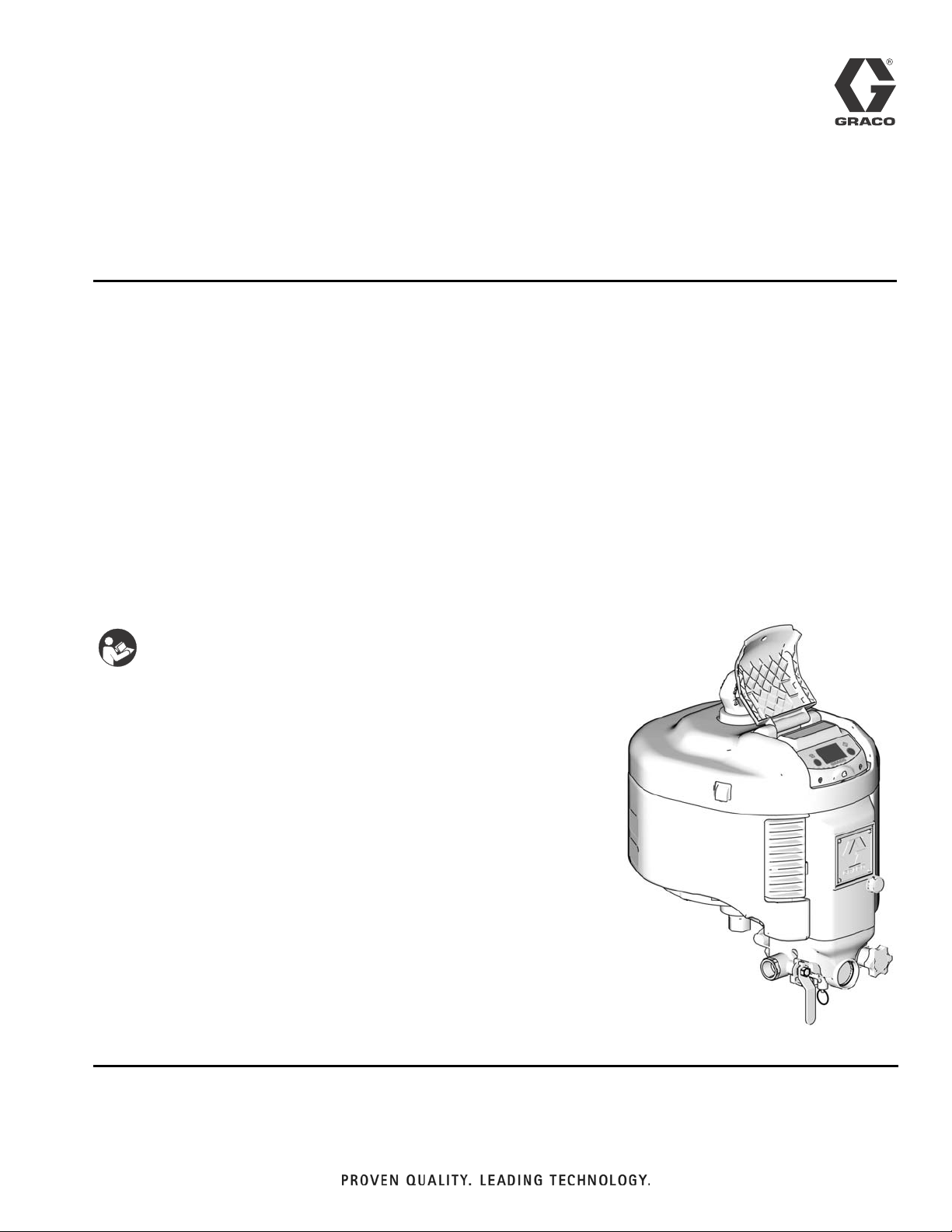
Integrated Air
311239H
Control Modules
Integrated air controls for use with NXT® Model 2200, 3400, and 6500 Air Motors. For
professional use only.
100 psi (0.69 MPa, 6.9 bar) Maximum Regulated Working Pressure
NXT011, Series E
With locking air regulator and 110 psi (0.76 MPa, 7.6 bar) relief valve
NXT021, Series E
With non-locking air regulator and 110 psi (0.76 MPa, 7.6 bar) relief valve
EN
NXT031, Series E
With locking air regulator and 85 psi (0.58 MPa, 5.8 bar) relief valve
Important Safety Instructions
Read all warnings and instructions in this manual
and in NXT air motor manual 311238. Save these
instructions.
Integrated Air Control Module shown
mounted on an NXT Air Motor
TI8233c
Page 2

Related Manuals
Contents
Related Manuals . . . . . . . . . . . . . . . . . . . . . . . . . . . 2
Warnings . . . . . . . . . . . . . . . . . . . . . . . . . . . . . . . . . 3
Installation . . . . . . . . . . . . . . . . . . . . . . . . . . . . . . . . 4
Operation . . . . . . . . . . . . . . . . . . . . . . . . . . . . . . . . . 5
Troubleshooting . . . . . . . . . . . . . . . . . . . . . . . . . . . . 7
Repair . . . . . . . . . . . . . . . . . . . . . . . . . . . . . . . . . . . . 9
Related Manuals
Manuals are available at www.graco.com.
This manual is available in the following languages:
Manual Language
3A0081 Chinese
3A0082 Danish
3A0083 French
3A0084 Finnish
3A0085 German
3A0086 Greek
Parts . . . . . . . . . . . . . . . . . . . . . . . . . . . . . . . . . . . . 12
Accessories . . . . . . . . . . . . . . . . . . . . . . . . . . . . . . 13
Schematic Diagram . . . . . . . . . . . . . . . . . . . . . . . . 14
Technical Data . . . . . . . . . . . . . . . . . . . . . . . . . . . . 15
Graco Standard Warranty . . . . . . . . . . . . . . . . . . . 16
Graco Information . . . . . . . . . . . . . . . . . . . . . . . . . 16
3A0087 Italian
3A0088 Japanese
3A0089 Korean
3A0090 Norwegian
3A0091 Polish
3A0092 Portuguese
312917 Russian
313800 Spanish
3A0093 Swedish
3A0094 Turkish
2 311239H
Page 3
Warnings
Warnings
The following warnings are for the setup, use, grounding, maintenance, and repair of this equipment. The exclamation point symbol alerts you to a general warning and the hazard symbols refer to procedure-specific risks. Refer
back to these Warnings. Additional, product-specific warnings may be found throughout the body of this manual
where applicable.
WARNING
PRESSURIZED EQUIPMENT HAZARD
Fluid from the gun/dispense valve, leaks, or ruptured components can splash in the eyes or on skin and
cause serious injury.
• Follow Pressure Relief Procedure in this manual, when you stop spraying and before cleaning,
checking, or servicing equipment.
• Tighten all fluid connections before operating the equipment.
• Check hoses, tubes, and couplings daily. Replace worn or damaged parts immediately.
PERSONAL PROTECTIVE EQUIPMENT
You must wear appropriate protective equipment when operating, servicing, or when in the operating
area of the equipment to help protect you from serious injury, including eye injury, inhalation of toxic
fumes, burns, and hearing loss. This equipment includes but is not limited to:
• Protective eyewear
• Clothing and respirator as recommended by the fluid and solvent manufacturer
•Gloves
• Hearing protection
EQUIPMENT MISUSE HAZARD
Misuse can cause death or serious injury.
• Do not operate the unit when fatigued or under the influence of drugs or alcohol.
• Do not exceed the maximum working pressure or temperature rating of the lowest rated system
component. See Technical Data in all equipment manuals.
• Use fluids and solvents that are compatible with equipment wetted parts. See Technical Data in all
equipment manuals. Read fluid and solvent manufacturer’s warnings. For complete information
about your material, request MSDS forms from distributor or retailer.
• Check equipment daily. Repair or replace worn or damaged parts immediately with genuine Graco
replacement parts only.
• Do not alter or modify equipment.
• Use equipment only for its intended purpose. Call your Graco distributor for information.
• Route hoses and cables away from traffic areas, sharp edges, moving parts, and hot surfaces.
• Do not kink or over bend hoses or use hoses to pull equipment.
• Keep children and animals away from work area.
• Comply with all applicable safety regulations.
311239H 3
Page 4
Installation
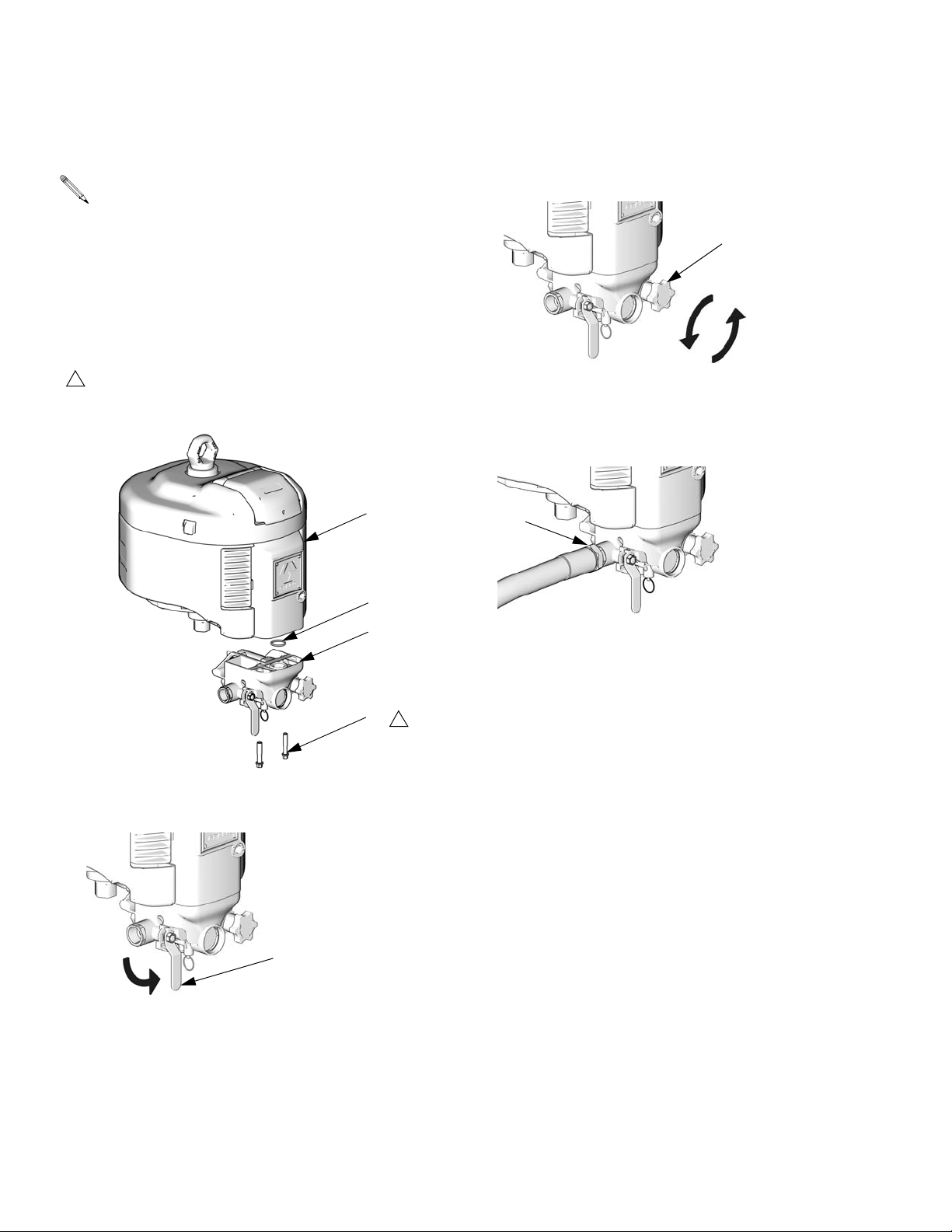
Installation
Air Control Modules NXT011 and NXT031 (locking
air regulator) and NXT021 (non-locking air regulator) are available.
1. Install supplied o-ring (43) into counterbore on upper
side of air control module (D). Fasten module to air
motor (M) with two supplied screws (44). Start
threading screws by hand before using a tool.
Torque to 20 ft-lb (27.1 N•m).
1
Screws are thread-forming. Start threading by hand
before using a tool. Torque to 20 ft-lb (27.1 N•m).
M
43
3. Turn air regulator knob (C) fully counterclockwise.
C
TI8322c
4. Hold the 3/4 npt(f) air inlet fitting (A) with a 1-5/16 in.
wrench to prevent it from turning while securely connecting the air supply hose.
A
TI8235c
2. Close bleed-type master air valve (B).
B
D
44
1
TI8323c
TI8322c
4 311239H
Page 5
Operation
Operation
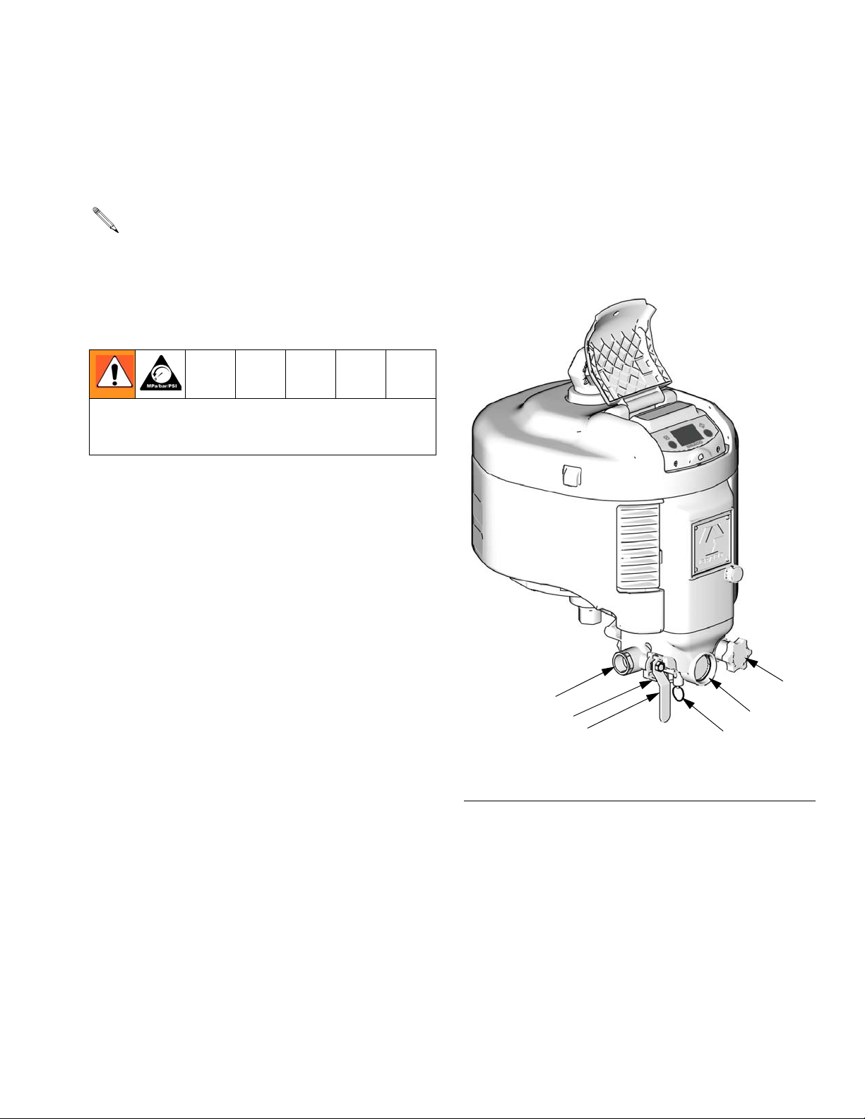
Component Identification
Air Control Modules NXT011 and NXT031 (locking
air regulator) and NXT021 (non-locking air regulator) include air line components in an integrated
assembly. See F
Bleed-type Master Air Valve (B)
Trapped air can cause the pump to cycle unexpectedly,
which could result in serious injury from splashing or
moving parts.
The bleed-type master air valve is required in your system to relieve air trapped between it and the air motor
when the valve is closed.
Air Regulator (C)
IG. 1.
Key for F
A Air Inlet, 3/4 npt(f)
B Bleed-type Master Air Valve
C Air Regulator Adjustment Knob (locking or non-locking)
D Air Pressure Gauge
E Air Filter (partially hidden)
F Safety Relief Valve
IG. 1
Adjusts air pressure to the motor and fluid outlet pressure of pump. View the gauge (D) to read air pressure.
Air Filter (E)
Removes harmful contaminants from entering the air
control module and air motor.
Safety Relief Valve (F)
Automatically opens to relieve air pressure, to prevent
pump overpressurization.
A
E
B
FIG. 1: Air Control Module Mounted on NXT Air Motor
F
C
D
TI8233c
311239H 5
Page 6

Operation
Startup Locking Regulator (NXT011 and
1. Turn air regulator knob (C) fully counterclockwise.
C
TI8322c
A small amount of air venting
through knob assembly (18) is
normal.
2. Open bleed-type master air valve (B).
NXT031 only)
1. To lock pressure setpoint, push knob (C) in.
C
TI8236c
2. Pull knob out to unlock, then adjust regulator to
desired pressure setpoint.
C
TI8236c
B
TI8236c
3. Turn air regulator knob (C) clockwise until air pressure reaches desired setpoint.
C
TI8236c
Shutdown
Close bleed-type master air valve (B).
B
TI8235c
6 311239H
Page 7

Troubleshooting
Problem Cause Solution
Troubleshooting
Excess air leaking from regulator
housing, or gauge shows unstable
regulated pressure.
Air leaking from quick exhaust vent
hole.
Air leaking from ball valve vent hole. Loose inlet fitting (32a). Tighten inlet fitting. See page 11.
Regulator does not regulate pressure.
Loose or worn diaphragm (17d). Tighten housing or repair regulator
using repair kit NXT095. See page
10.
Worn seat (17e) or poppet (17f). Repair regulator using repair kit
NXT095. See page 10.
Main spool seals or relief valve worn. Replace with spool kit NXT098,
page 10.
Quick exhaust poppet (20b) or seat
(20a) worn.
Worn poppet o-ring (20c). Replace with quick exhaust repair kit
Quick exhaust poppet (20b) or seat
(20a) worn.
Worn valve seals (32b, 32d). Repair ball valve using repair kit
Worn spool o-rings or worn/damaged
diaphragm (17d).
Replace with quick exhaust repair kit
NXT099, page 10.
NXT099, page 10.
Replace with quick exhaust repair kit
NXT099, page 10.
NXT097. See page 11.
With air on and bleed-type master air
valve (B) open, unscrew the regulator
housing (19).
Gauge will not go to 0 when ball valve
is open and knob is turned counter-clockwise to 0.
• If pressure drops, diaphragm is
damaged. Install Repair Kit
NXT095, page 10.
• If air leaks out bottom orifice,
spool o-rings are worn. Install
Repair Kit NXT098, page 10.
Washer (17c) is on wrong side of diaphragm (17d).
Pilot air seat (17e) is not fully seated. Turn pilot air seat (17e) in until if fully
Seal (3) is too thin or damaged causing air to leak into pilot air chamber.
Move washer (17c) to spring side of
diaphragm.
seats.
Replace snail seal (3). Seal should
have a minimum thickness of 0.065
in. (1.65 mm).
311239H 7
Page 8

Troubleshooting
Problem Cause Solution
Gauge pressure increases above set
point pressure.
Air pressure drops when pump is
cycling.
Leak across rear spool (8) o-ring,
which raises pilot air pressure even
Replace spool assembly (8) with
spool kit NXT098.
while spraying.
Leak across front spool (8) o-ring,
which raises air motor pressure when
Replace spool assembly (8) with
spool kit NXT098.
stalled.
Spool assembly (8) sticking. Clean and lubricate spool (8). Add oil
to filter cup and run motor. Or, add a
lubricator to air supply.
Seal (3) leaking. Replace snail seal (3). Seal should
have a minimum thickness of 0.065
in. (1.65 mm).
Side hole or through vent plugged on
diaphragm tube (17d).
Air hose has too small of an inside
Clean through vent and side 0.015 in.
(0.381 mm) hole.
Use a 3/4 in. ID air hose.
diameter.
Air supply is not adequate. (Check
Use a larger air compressor.
gauge between hose and inlet.)
Air filter (6) is plugged. Replace air filter with kit NXT092. Or,
upgrade to a larger coalescing filter
with a manual drain (NXT094), or
with an automatic drain (NXT093).
See Accessories (page 13) and
manual 406659.
8 311239H
Page 9

Repair
Pressure Relief Procedure
Repair
Replace Filter Element
1. Relieve pressure, page 9.
Follow Pressure Relief Procedure when you stop
spraying and before cleaning, checking, or servicing
equipment.
1. Close bleed-type master air valve (B).
B
TI8235c
2. Make sure gauge (D) reads zero (0). If not, pull on
pressure relief ring to bleed off air pressure.
2. Remove filter bowl (E) with wrench. Remove filter
element (G).
3. Install new filter element (G) on boss within the bowl
(E). Reinstall bowl 1/4 turn past handtight.
G
E
TI8237b
Replace Gauge
1. Relieve pressure, page 9.
2. See Parts drawing, page 12. Using a 7/16 open-end
wrench on the flats, unscrew old gauge (31).
D
3. Turn air regulator knob (C) fully counterclockwise.
C
311239H 9
TI8235c
TI8322c
3. Apply PTFE tape to threads before installing new
gauge.
Page 10

Repair
Spool Repair Kit NXT098
1. Relieve pressure, page 9.
2. See Parts drawing, page 12. Using a 1/4 in. drive
ratchet or a 3/8 in. deep well socket, remove 2
screws (37). Use a 3/8 in. open-end wrench to
remove the third screw (37) and disassemble front
cover (5) from housings (1, 2). Remove spring (16).
3. Pull the spool assembly (8) out of the housing (1).
Use a pliers to carefully pull the spool assembly out
by the tip.
4. Clean and lubricate the bore in the housing (1).
5. Install the new spool (8), spring (16), and o-ring (38).
Regulator Repair Kit NXT095
Quick Exhaust Repair Kit NXT099
1. Relieve pressure, page 9.
2. See Parts drawing, page 12. Using a 3/8 in. deep
well socket, remove 2 screws (37). Use a 3/8 in.
open-end wrench to remove the third screw (37) and
disassemble front cover (5) from housings (1, 2).
Remove spring (16).
3. Remove seat (20a) with large flat blade screwdriver.
Work out the poppet (20b) from the hole beneath the
poppet using an o-ring pick or an allen wrench.
4. Liberally grease housing threads to avoid damaging
o-ring (20c) on new poppet (20b). Install new poppet
with o-ring. Install new seat (20a) until it bottoms out
tight in the housing.
1. Relieve pressure, page 9.
2. See Parts drawing, page 12. Using a 1-3/8 in.
open-end wrench, unscrew the regulator housing
(19).
3. Remove adjustment screw (17a), spring (17b), slip
ring (17c), diaphragm (17d), and washer (48).
4. Using #2 Phillips screwdriver, remove valve seat
(17e) slowly to avoid damaging flutes. Remove valve
assembly (17f) and spring (17g).
5. Use all new parts in the kit. Reinstall the spring
(17g), valve assembly (17f), washer (48), and valve
seat (17e). Tighten seat slowly to avoid damaging
flutes.
6. Do not apply any lubricant on the seating area of the
diaphragm (17d). Reinstall diaphragm, slip ring
(17c), spring (17b), and adjustment screw (17a).
10 311239H
Page 11

Repair
Ball Valve Seal Repair Kit NXT097
1. Relieve pressure, page 9.
2. See Parts drawing, page 12. Remove the inlet fitting
(32a) using a 1 5/16 in. wrench.
3. See F
4. See F
IG. 2. Move the handle to the 7:30 position.
Remove the outboard seal (32b) with an o-ring pick.
IG. 2. Move the handle to the 6:00 position.
Remove the ball (32c) using adhesive tape. Remove
the inboard seal (32d) with an o-ring pick.
Use notes on page 12 as a guide while completing
step 5.
6. Install the new outboard seal (32b) and inlet
fitting (32a). Torque to 500 in-lb (56 N•m).
The stem seal components (32e-32k) do not need
replacement unless leakage is noted. If necessary,
replace parts as shown on page 12.
9:00
7:30
6:00
IG. 2. Valve Handle Positions
F
TI8803a
5. Install the new inboard seal (32d). Install the new
ball (32c) with the notch (N) facing the front of the
module, so it engages the valve stem (33). The flat
spot on the ball must face inward.
311239H 11
Page 12

Parts
Parts
NXT011 and NXT031 Locking Integrated Air Control Module
NXT021 Non-Locking Integrated Air Control Module
32e
32f
32g
32h
32j 32k
34 35 33
4
5
32a
37
1
2
32b
7
8
32c
8
20a 20b 20c
2
8
32d
3
1
37
N
1
8
17f†
17g†
17f†
48†
8
8
16
38
7
6
4
17e†
5
17d†
17c†
31
18
18
17a†
3
17b†
50
TI8234d
1
Torque to 140 in-lb (16 N•m).
2
Torque to 500 in-lb (56 N•m).
3
Torque to 240 in-lb (27 N•m).
4
43
44
6
TI8323b
12 311239H
Torque to 130 in-lb (15 N•m).
5
Install bowl 1/4 turn past handtight.
6
Screws are thread-forming. Start
threading by hand before using a tool.
Torque to 20 ft-lb (27.1 N•m).
7
Apply blue thread lock sealant.
8
Apply lithium grease.
Page 13

Accessories
Ref.
No. Part No. Description Qty
1 15G298 HOUSING, right 1
2 15G299 HOUSING, left 1
3* 15G439 GASKET; nitrile 1
4 277109 BOWL, filter 1
5 277107 COVER, front 1
6 NXT092 ELEMENT, filter, 40 micron; pack-
age of 10
7* 103209 O-RING; fluoroelastomer 1
8 NXT098 SPOOL, valve 1
16 119987 SPRING, compression 1
17† NXT095 KIT, repair, regulator; includes
items 17a-17g
18 NXT090 KNOB ASSEMBLY, regulator, lock-
ing; NXT011 and NXT031
NXT091 KNOB ASSEMBLY, regulator,
non-locking; NXT021
20 NXT099 KIT, relief valve; includes items
20a-20c
31 108190 GAUGE, pressure, air 1
32 NXT097 KIT, repair, ball valve; 3/4 npt(f)
inlet; includes items 32a-32k
33 15F726 STEM, ball valve 1
34 15F727 INSERT, threaded, ball valve 1
35* C20145 O-RING; buna-N 1
37 119426 SCREW, machine, hex washer hd,
thread-forming; 1/4-20 x 1 in. (25
mm)
38* 115078 O-RING; nitrile 1
43 110782 O-RING; buna-N 1
44 120089 SCREW; 3/8-16 x 1-3/4 in. (44 mm) 2
48† 187509 WASHER, flat 1
50 113498 RELIEF VALVE, safety; 110 psi
(0.76 MPa, 7.6 bar); NXT011 and
NXT021
108124 RELIEF VALVE, safety; 75 psi (0.51
MPa, 5.1 bar); NXT031
Accessories
Kit Description
NXT090 Locking knob kit
NXT091 Non-locking knob kit
1
1
1
1
1
1
7
1
1
NXT092 Filter element, 40 micron, package of 10
NXT093 Coalescing filter with automatic drain
NXT094 Coalescing filter with manual drain
NXT095 Regulator repair kit
NXT096 Seal repair kit
NXT097 Ball valve repair kit
NXT098 Spool valve kit
NXT099 Relief valve kit
116635 Element replacement kit. For use with
kits NXT093 and NXT094.
* Parts included in Seal Repair Kit NXT096 (purchase
separately).
Recommended spare parts. Keep on hand to avoid
downtime.
† Parts included in Air Regulator Repair Kit NXT095
(purchase separately.)
311239H 13
Page 14

Schematic Diagram
Schematic Diagram
Bleed-Type Ball Valve
Air Filter
Pilot Valve
Pilot Vent
Diaphragm
AIR IN
Quick Air Purge
ATMOSPHERE
TO MOTOR
Air Pressure
Gauge
Spool
Overpressure Safety
Relief Valve
Atmosphere
Air Regulator
Adjustment Knob
Supply Pressure
Regulated Pressure
Pilot Pressure
14 311239H
Page 15

Technical Data
Technical Data
Maximum air inlet pressure 140 psi (0.97 MPa, 9.7 bar)
Maximum regulated working pressure 100 psi (0.69 MPa, 6.9 bar)
Maximum operating temperature 140°F (60°C)
Air Inlet Size 3/4 npt(f)
Air Gauge Port Size 1/8 npt(m)
Height 6.5 in. (165 mm)
Width 6.75 in. (171 mm)
Depth 4.75 in. (121 mm)
Weight 5.1 lb (2.3 kg)
Materials of construction Chrome, brass, aluminum, acetal, fluorocarbon rubber,
nylon, nitrile rubber, fluoroelastomer
311239H 15
Page 16

Graco Standard Warranty
Graco warrants all equipment referenced in this document which is manufactured by Graco and bearing its name to be free from defects in
material and workmanship on the date of sale to the original purchaser for use. With the exception of any special, extended, or limited warranty
published by Graco, Graco will, for a period of twelve months from the date of sale, repair or replace any part of the equipment determined by
Graco to be defective. This warranty applies only when the equipment is installed, operated and maintained in accordance with Graco’s written
recommendations.
This warranty does not cover, and Graco shall not be liable for general wear and tear, or any malfunction, damage or wear caused by faulty
installation, misapplication, abrasion, corrosion, inadequate or improper maintenance, negligence, accident, tampering, or substitution of
non-Graco component parts. Nor shall Graco be liable for malfunction, damage or wear caused by the incompatibility of Graco equipment with
structures, accessories, equipment or materials not supplied by Graco, or the improper design, manufacture, installation, operation or
maintenance of structures, accessories, equipment or materials not supplied by Graco.
This warranty is conditioned upon the prepaid return of the equipment claimed to be defective to an authorized Graco distributor for verification of
the claimed defect. If the claimed defect is verified, Graco will repair or replace free of charge any defective parts. The equipment will be returned
to the original purchaser transportation prepaid. If inspection of the equipment does not disclose any defect in material or workmanship, repairs will
be made at a reasonable charge, which charges may include the costs of parts, labor, and transportation.
THIS WARRANTY IS EXCLUSIVE, AND IS IN LIEU OF ANY OTHER WARRANTIES, EXPRESS OR IMPLIED, INCLUDING BUT NOT LIMITED
TO WARRANTY OF MERCHANTABILITY OR WARRANTY OF FITNESS FOR A PARTICULAR PURPOSE.
Graco’s sole obligation and buyer’s sole remedy for any breach of warranty shall be as set forth above. The buyer agrees that no other remedy
(including, but not limited to, incidental or consequential damages for lost profits, lost sales, injury to person or property, or any other incidental or
consequential loss) shall be available. Any action for breach of warranty must be brought within two (2) years of the date of sale.
GRACO MAKES NO WARRANTY, AND DISCLAIMS ALL IMPLIED WARRANTIES OF MERCHANTABILITY AND FITNESS FOR A
PARTICULAR PURPOSE, IN CONNECTION WITH ACCESSORIES, EQUIPMENT, MATERIALS OR COMPONENTS SOLD BUT NOT
MANUFACTURED BY GRACO. These items sold, but not manufactured by Graco (such as electric motors, switches, hose, etc.), are subject to
the warranty, if any, of their manufacturer. Graco will provide purchaser with reasonable assistance in making any claim for breach of these
warranties.
In no event will Graco be liable for indirect, incidental, special or consequential damages resulting from Graco supplying equipment hereunder, or
the furnishing, performance, or use of any products or other goods sold hereto, whether due to a breach of contract, breach of warranty, the
negligence of Graco, or otherwise.
FOR GRACO CANADA CUSTOMERS
The Parties acknowledge that they have required that the present document, as well as all documents, notices and legal proceedings entered into,
given or instituted pursuant hereto or relating directly or indirectly hereto, be drawn up in English. Les parties reconnaissent avoir convenu que la
rédaction du présente document sera en Anglais, ainsi que tous documents, avis et procédures judiciaires exécutés, donnés ou intentés, à la suite
de ou en rapport, directement ou indirectement, avec les procédures concernées.
Graco Information
For the latest information about Graco products, visit www.graco.com.
TO PLACE AN ORDER, contact your Graco distributor or call to identify the nearest distributor.
Phone: 612-623-6921 or Toll Free: 1-800-328-0211 Fax: 612-378-3505
All written and visual data contained in this document reflects the latest product information available at the time of publication.
GRACO INC. AND SUBSIDIARIES • P.O. BOX 1441 • MINNEAPOLIS MN 55440-1441 • USA
Copyright 2006, Graco Inc. All Graco manufacturing locations are registered to ISO 9001.
Graco reserves the right to make changes at any time without notice.
Original instructions. This manual contains English. MM 311239
Graco Headquarters: Minneapolis
International Offices: Belgium, China, Japan, Korea
www.graco.com
Revised 07/2011
 Loading...