

Page 1
Operating Instructions
Form No. 309043
Rev. G
This manual contains important
warnings and information.
READ AND KEEP FOR REFERENCE.
INSTRUCTIONS
To find your Graco/M
D See the enclosed Graco/MAGNUM Authorized Service Centers list
D Visit our website at www.graco.com
D Call us at 1–888–541–9788
t
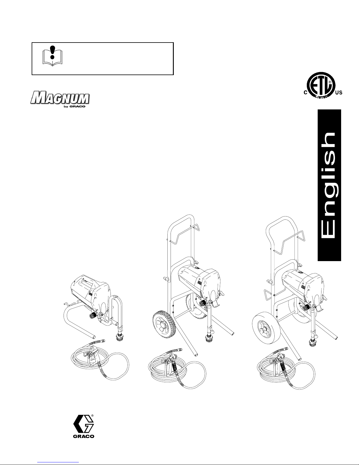
XR Series Airless Sprayers
MAGNUM XR9, Model 232750, Series A
0.38 gpm (1.44 lpm) sprayer on heavy-duty deluxe cart, 50 ft (15.2 m) hose, and
SG3 pro metal gun with reversible tip and guard
3000 psi (21 MPa, 207 bar) Maximum Working Pressure
MAGNUM XR7, Model 232745, Series A
0.31 gpm (1.17 lpm) sprayer on heavy-duty cart, 50 ft (15.2 m) hose, and
SG2 metal gun with reversible tip and guard
3000 psi (21 MPa, 207 bar) Maximum Working Pressure
MAGNUM XR5, Model 232740, Series A
0.24 gpm (0.91 lpm) stand-mount sprayer, 25 ft (7.6 m) hose, and
SG1 gun with reversible tip and guard
2800 psi (19 MPa, 193 bar) Maximum Working Pressure
AGNUM authorized service center
Features of every MAGNUM sprayer
D 120V, permanent magnet, open-frame DC motor
D Power Flusht cleaning (for flushing with water)
D XR Power-Pistont hardened stainless steel pump
D Demand Deliveryt system (pump stops when
spraying stops)
D InstaCleant filter system
9557A
MAGNUM XR5
Model 232740
MAGNUM XR7
Model 232745
9558A 9559A
MAGNUM XR9
Model 232750
GRACO INC. P.O. BOX 1441 MINNEAPOLIS, MN 55440–1441
ECOPYRIGHT 1999, GRACO INC.
Graco Inc. is registered to I.S. EN ISO 9001
Page 2
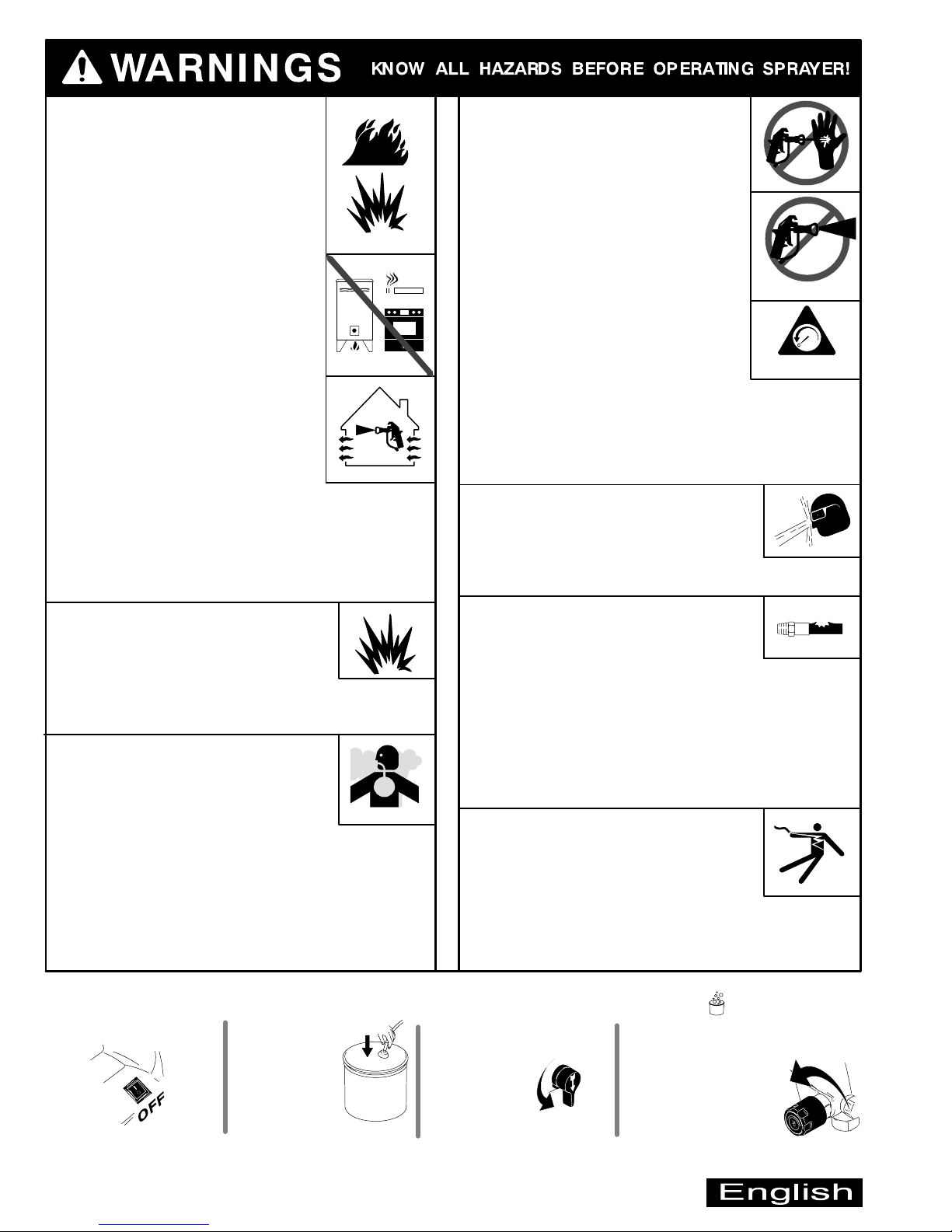
FIRE AND EXPLOSION HAZARD
A Fire and explosion hazard exists
any time you spray or flush flammable fluids.
To help prevent fire or explosion when
spraying flammable fluids
D Be sure sprayer is adequately grounded
through electrical outlet as follows:
– Use only grounded electrical outlets.
– Use only 3-wire extension cords.
– Make sure ground prongs are intact
on sprayer and extension cords.
D Motor in this sprayer is a source of
sparks. Keep sprayer in well-ventilated
area, at least 20 feet (6 meters) away
from gun when spraying or flushing.
D Do not use plastic drop cloths when
spraying or flushing flammable fluids.
D Avoid all ignition sources, such as pilot
lights, cigarettes, and plastic drop cloths
(static arc hazard). Do not plug in or
unplug power cords or turn lights on or
off in spray area.
D Tape wall switches to prevent them from being turned
off or on.
D Do not smoke in spray area.
D Use only M
D Use outdoors or in a well-ventilated area.
AGNUM or Graco airless paint hoses.
FLUID INJECTION HAZARD
If high-pressure fluid pierces skin,
the injury might look like “just a cut”
but is a serious wound. Get
immediate medical attention.
To help prevent injection
D Always put trigger safety lever in SAFETY
ON position when not spraying.
D Always shut off power and relieve pressure
when you stop spraying and before you
service or clean sprayer, remove parts, or
repair leaks. See Pressure Relief
Procedure below.
D Do not allow children to use this equipment.
D Keep clear of tip, and never point gun at
yourself or anyone else.
STARTUP HAZARD AFTER THERMAL OVERLOAD
Motor has thermal overload switch to
shut itself down if overheated. To reduce risk of injury
from motor restarting unexpectedly when it cools, always
turn Power switch OFF if motor shuts down.
FLUID SPLASHBACK HAZARD
To avoid splashing fluid when spraying
into pail, always aim at inside wall of pail.
Make sure gun is assembled with correct
gasket for fluid being sprayed. See Instal-
ling Tip & Guard in enclosed Operator’s Quick Guide.
SAFETY ON
pressure
EQUIPMENT MISUSE HAZARD
Do not use 1,1,1–trichloroethane, methylene
chloride, other halogenated hydrocarbon
solvents or fluids containing such solvents
in pressurized aluminum equipment such as
this sprayer and gun. Such use could result in
chemical reaction and possible explosion.
TOXIC FLUID HAZARD
Hazardous fluid or toxic fumes can cause
serious injury or death if splashed in eyes
eyes or on skin, inhaled, or swallowed.
To help prevent injury or death from
toxic fluids
D Know specific hazards of fluid you are using; store
hazardous fluid in approved tub; dispose of
hazardous fluid according to all local, state, and
national guidelines.
D Always wear protective eyewear, gloves, clothing, and
respirator as recommended by fluid and solvent
manufacturer.
Pressure Relief Procedure (See Fluid Injection Hazard above)
1. Turn Power switch OFF.
2. Place prime tube
in waste pail.
PRESSURIZED EQUIPMENT HAZARD
M
AGNUM sprayers are capable of
producing up to 3000 psi (21 MPa, 207 bar)
maximum working pressure. To avoid
component rupture and injury, do not operate sprayer
with components rated less than pressure of sprayer.
Sprayer is equipped with a pressure drain that
automatically relieves overpressure in the event of a fault
condition. This automatic pressure relief may cause
splashing of fluid. Correct fault before you resume spraying.
NOTE: Inadequate flushing and/or dried paint in drain
system may prevent proper overpressure relief.
ELECTRIC SHOCK HAZARD
Gun, hose, and sprayer are grounded
through electrical cord of sprayer.
To help prevent electric shock
D Use only grounded electrical outlets.
D Only use 3-wire extension cords.
D Make sure ground prongs are intact on sprayer and
extension cords.
D Keep electrical connections and inside of shroud dry.
3. Turn Spray/Prime valve to
PRIME (pointing down) to
relieve pump
pressure.
4. Align the (bucket) symbol on
the pressure control knob and the
arrow on the sprayer.
2 309043
WASTE
PAIL
PRIME
Page 3
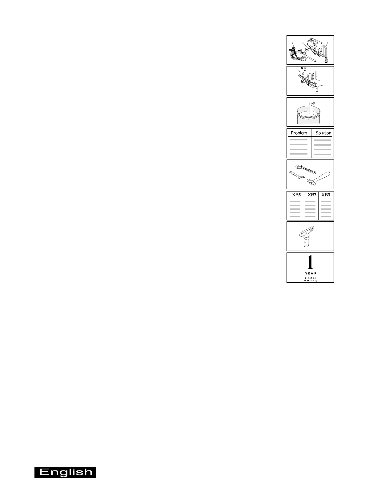
Section Page
Component Identification and Function 4. . . . . . . . . . . . . . .
Preparing to Spray 6. . . . . . . . . . . . . . . . . . . . . . . . . . . . . . . . . . .
Pail Flushing 8. . . . . . . . . . . . . . . . . . . . . . . . . . . . . . . . . . . . . . . .
Troubleshooting 10. . . . . . . . . . . . . . . . . . . . . . . . . . . . . . . . . . .
Maintenance and Service 12. . . . . . . . . . . . . . . . . . . . . . . . . . .
Technical Data 13. . . . . . . . . . . . . . . . . . . . . . . . . . . . . . . . . . . . .
A
B
FLUSH
C
Accessories 14. . . . . . . . . . . . . . . . . . . . . . . . . . . . . . . . . . . . . . .
Limited Warranty 16. . . . . . . . . . . . . . . . . . . . . . . . . . . . . . . . . . .
309043 3
Page 4
A
B
C
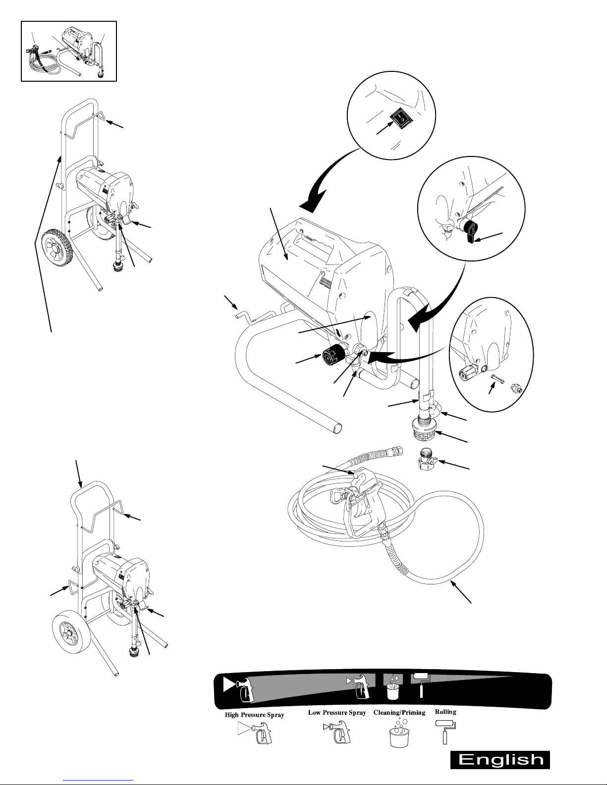
Component Identification and Function
ON
W
X
K
9558A
MAGNUM XR7
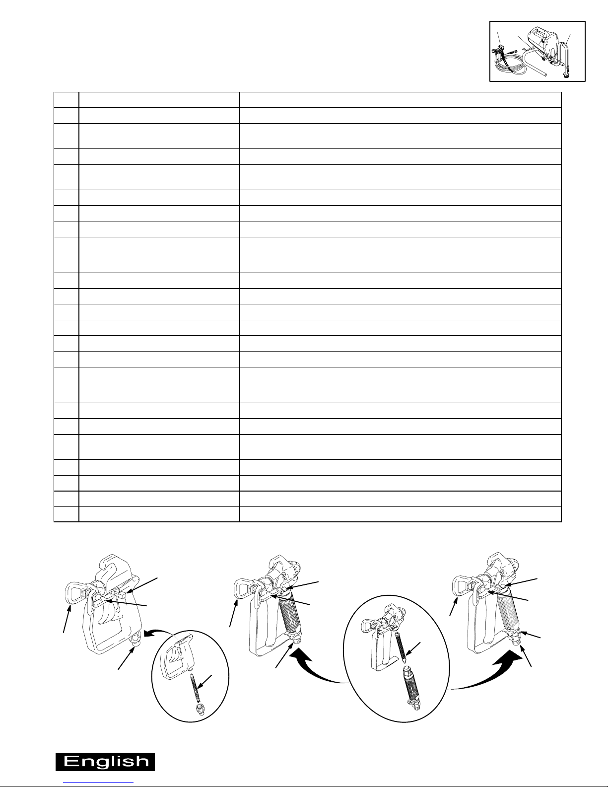
Connect cart handles on XR7 and XR9
as follows:
1. Remove thumbscrews and bolts from
cart frame.
2. Position handle on frame as shown, and align
bolt holes in handle with bolt holes in frame.
3. Run bolts through holes with heads pointing
toward each other, and tighten thumbscrews
by hand.
NOTE: For space-saving configuration, loosen
(but do not remove) thumbscrews, and fold
handle forward over sprayer shroud.
N
B
OFF
A
J
F
*
C
D
K
G
E
H
MAGNUM XR5
P
L
Y
W
W
X
K
9559A
MAGNUM XR9
4 309043
9560A
M
*To select a function, align the icon with the arrow on the sprayer.
Page 5
A
Component Identification and Function
A Electric motor (inside of shroud) Provides mechanical power to pump
B Power switch For manually turning on/off electrical power to motor (“I” is ON / “0” is OFF)
C Pressure Control knob For manually increasing (turn clockwise) and decreasing (turn
counter-clockwise) fluid pressure in pump, hose, and gun
D Pump fluid outlet fitting Threaded connection for paint hose
E InstaClean fluid filter D Filters fluid coming out of pump to reduce tip clogging and improve finish
D Self cleans during pressure relief
F Power-Piston pump (behind cover) Pumps and pressurizes fluid and delivers it to paint hose
G Suction tube Draws fluid from paint pail into pump
H Prime tube (with diffuser) Drains fluid in system during priming and pressure relief
J Spray/Prime valve control D Directs pressurized fluid to paint hose in SPRAY position (pointing forward)
D Directs fluid to prime tube in PRIME position (pointing down)
D Automatically relieves system pressure in overpressure situations
K Fluid inlet connection Where suction tube connects to pump
L Inlet screen Prevents debris from entering pump
M Paint hose Transports high-pressure fluid from pump to gun
N Cord wrap bracket For stowing power cord (MAGNUM XR5 only)
P Airless spray gun Manually-controlled, hand-held on/off device for fluid being sprayed
Q Tip guard Reduces risk of fluid injection injury
R Reversible tip D Atomizes fluid being sprayed, forms spray pattern, and controls fluid flow
according to hole size
D Reverses for unclogging without disassembly
S Trigger safety lever Prevents accidental triggering of gun
T Gun fluid inlet fitting Threaded connection for paint hose
U Smooth Glidet swivel
(SG3 gun only)
V Gun fluid filter (in handle) Filters fluid entering gun to reduce tip clogging and improve finish
W Hose/Cord wrap bracket For stowing paint hose and power cord (MAGNUM XR7 and XR9 only)
X Pail hanger For transporting pail by its handle (MAGNUM XR7 and XR9 only)
Y Power Flush attachment (included) Connects garden hose to suction tube for power flushing water-base fluids
Allows gun to swivel without twisting paint hose
B
C
SG1 Gun
included with MAGNUM XR5
S
R
Q
T
SG2 Gun
included with MAGNUM XR7
Q
V
9561A
T
SG3 Gun
included with MAGNUM XR9
S
R
S
R
Q
V
U
T
9562A
309043 5
Page 6

Preparing to Spray
(
For Setup, Priming, and Installing Tip & Guard instructions, see the enclosed Operator’s Quick Guide.
Selecting a Tip Hole Size
Tips come in a variety of hole sizes for a range of fluids. Your MAGNUM sprayer includes the tip most likely to satisfy
common spraying applications. Use the following table to determine the range of recommended tip hole sizes for each
fluid type. If you need a tip other than the one supplied, see the Reversible Tip Selection Chart on page 14.
Tip Hole Sizes
expressed as diameter,
based on area of elliptical
orifice)
lacquers and
stains
enamels
Coatings
oil-base
primers and paints
interior
latex paints
0.011 in. (0.28 mm) X
0.013 in. (0.33 mm) X X X X
0.015 in. (0.38 mm) X X X X
0.017 in. (0.43 mm) X X X
0.019 in. (0.48 mm) X
HINTS:
D
The tip included with your sprayer is one size smaller
than the maximum tip hole size the sprayer supports.
As you spray, the tip wears and enlarges. Starting
with a tip hole size smaller than the maximum will
allow you to spray within the rated flow capacity of
the sprayer while using the tip you selected.
D Maximum tip hole size that each MAGNUM sprayer
supports is as follows:
– XR5: New 0.015 in. (0.38 mm)
– XR7: New 0.017 in. (0.43 mm)
– XR9: New 0.019 in. (0.48 mm)
exterior
latex paints
6 309043
Page 7

Preparing to Spray
Using the Right Tip for the Job
Consider the coating and the surface to be sprayed.
Make sure you use the best tip hole size for that coating
and the best fan width for that surface.
Tip Hole Size
Tip hole size controls the flow rate — the amount of
paint that comes out of the gun.
HINTS:
D
Generally, use larger tip hole sizes with thicker
coatings and smaller tip hole sizes with thinner
coatings.
D The maximum tip hole size that a sprayer can
support is related to its maximum flow rate. The
maximum tip hole size that each MAGNUM sprayer
supports is as follows:
– XR5: New 0.015 in. (0.38 mm)
– XR7: New 0.017 in. (0.43 mm)
– XR9: New 0.019 in. (0.48 mm)
D Tips wear with use and need periodic replacement.
Fan Width
Fan width is the size of the spray pattern, which
determines the area covered with each stroke. For a
given tip hole size, narrower fans deliver a thicker coat,
and wider fans deliver a thinner coat.
HINTS:
D
Select a fan width best suited for the surface being
sprayed.
D Wider fans allow for faster coverage on broad, open
surfaces.
D Narrower fans allow for better control on small,
confined surfaces.
Understanding the Tip Number
The last three digits of the tip number (example:
RST413) contain information about the hole size and
about the fan width on the surface when the gun is held
12 in. (30.5 cm) from the surface being sprayed.
First digit when doubled
= approximate
fan width.
Last two digits = tip hole size
in thousands of an inch.
413 tip has 8 to 10 in.
fan width
413 tip has a
0.013 in. hole size
309043 7
Page 8

FLUSH
Pail Flushing
WARNING
See Fire and Explosion
on page 2.
Hazard
See Fluid Injection Hazard
on page 2.
This is the procedure for pail flushing with a compatible
flushing fluid. The assumed starting point for this
procedure is as follows:
D You have just finished spraying.
D System is under pressure.
D Power switch is OFF.
Pail Flushing HINTS:
D
If the flushing fluid is water, use at least 4 gallons
(15 liters).
D Keep the paint pail near. You will need it in Step 6 to
get unused paint out of the hose.
NOTE: In Step 1, the sprayer must be under pressure
for the InstaClean fluid filter system to be activated. If
the sprayer has no pressure, it needs to be primed. See
Priming in the enclosed Operator’s Quick Guide.
1. With Power switch OFF, lift suction tube and prime
tube from paint pail, and let them drain into paint for
awhile. Place suction tube in flushing fluid pail, and
place prime tube in waste pail. Turn Spray/Prime
valve to PRIME to relieve fluid pressure into waste
pail.
2. Align the bucket symbol on the pressure control
knob and the arrow on the sprayer. Trigger gun into
waste pail to relieve pressure that might be in hose.
NOTE: To minimize splashing, aim gun at inside wall of
empty waste pail.
WASTE
9567A
3. Remove tip & guard assembly from gun, and place
in flushing fluid pail.
FLUSHING
FLUID
9567A
4. Turn Power switch ON. Continue flushing until about
1/3 of flushing fluid is gone from flushing fluid pail.
WASTE
OFF
FLUSHING
FLUID
8 309043
PRIME
9567A
ON
WASTE
FLUSHING
FLUID
5. Turn Power switch OFF, and turn Prime valve to
SPRAY.
OFF
SPRAY
Page 9

Pail Flushing
Step 6 is for getting the paint in the hose back into the
paint container. A 50-foot (15 m) section of hose holds
approximately 1 quart (1 liter) of paint.
6. Trigger gun into paint pail, and turn Power switch
ON. When flushing fluid comes out of gun, release
trigger.
watch for flushing fluid
ON
PAINT
7. Move gun to waste pail, and trigger it to flush pump,
hose, and gun into waste pail. Continue until
remaining flushing fluid is gone from flushing fluid
pail.
NOTE: To minimize splashing, aim gun at inside wall of
pail.
FLUSH
10. Clean tip & guard assembly and gun filter with water
and a brush. Check InstaClean filter for debris. If
needed, clean with water and a brush.
NOTE: See InstaClean Fluid Filter on page 12.
SG2 / SG3
SG1
filter
9566A
11. Reassemble tip & guard assembly and filter.
SG1
SG2 / SG3
WASTE
9567A
See Pressure Relief
Procedure
on page 2.
8. Relieve the pressure.
9. Remove suction tube and prime tube from pails, and
wipe residue from suction tube, prime tube, and inlet
screen.
9561A
9562A
The sprayer is ready to spray a new coating or color
compatible with the fluid you just flushed with. If the next
coating is not compatible, flush with a compatible fluid
before you spray again.
NOTE: If you are storing the sprayer, see Preparing for
Storage
in the enclosed Operator’s Quick Guide.
309043 9
Page 10

Troubleshooting
ppy
gg
ppy
gg
Check everything in this Troubleshooting table before you bring the sprayer to a Graco
authorized service center.
For Basic Troubleshooting, see the enclosed Operator’s Quick Guide.
PROBLEM CAUSE SOLUTION
Power switch (B) is on and
sprayer is plugged in, but
pump does not cycle.
Pump cycles but does not
build up pressure.
Motor does not turn on when
sprayer is plugged in and
turned on.
Pressure is set at maximum, but
cannot achieve a good spray
pattern.
When paint is sprayed, it runs
down the wall or sags.
When paint is sprayed, coat is
not covering.
Motor or control is damaged. Return sprayer to Graco authorized service center.
Pump check valves are dirty or
damaged.
Spray/Prime valve is worn or
obstructed with debris
Electrical outlet is not providing
power or extension cord is
damaged or sprayer power
cord is damaged.
Paint is frozen or hardened in
pump.
Tip is too big for sprayer. Select a smaller tip. See Selecting a Tip Hole Size on page 6.
Tip is worn beyond capability
of sprayer.
Extension cord is too long or
not a heavy enough gauge.
Gun fluid filter is clogged. Clean or replace gun fluid filter (V). See Gun Fluid Filter on
InstaClean fluid filter is
clogged.
Inlet screen is clogged. Clean debris off inlet screen (L).
Pump valves are worn. Check for worn pump valves as follows: Prime sprayer with
Coat is going on too thick. Move gun faster.
Coat is going on too thin. Move gun slower.
Clean or replace check valves. See Pump Check Valves on
page 12.
Return sprayer to Graco authorized service center.
Try a different outlet or reset building circuit breaker or replace
extension cord/power cord.
Unplug sprayer from electrical outlet.
NOTE: If frozen, do not try to start sprayer until completely
thawed, or damage to motor, control board, and/or drivetrain
may occur.
Make sure power switch (B) is OFF. Place sprayer in warm area
for several hours, then plug in and turn on. Slowly increase
pressure setting to see if motor starts.
If paint hardened in sprayer, pump packings, valves, drivetrain,
or pressure switch may need to be replaced.
Replace tip. See Installing Tip & Guard in enclosed Operator’s
Quick Guide.
Replace extension cord.
page 12.
Clean or replace InstaClean fluid filter (E). See InstaClean
Fluid Filter on page 12.
paint (see Priming in enclosed Operator’s Quick Guide). Trigger
gun momentarily. When trigger is released, pump should cycle
momentarily and stop. If pump continues to cycle, pump
valves may be worn. See Pump Check Valves on page 12.
Choose tip with smaller hole size.
Choose tip with wider fan.
Make sure gun is far enough from surface.
Choose tip with larger hole size.
Choose tip with narrower fan.
Make sure gun is close enough to surface.
10 309043
Page 11

Troubleshooting
Motor is hot and runs
Vent holes in shroud are
Keep vent holes in shroud clear of obstructions and overspray,
y
Th
as soon as sprayer is plugged
PROBLEM CAUSE SOLUTION
Motor is hot and runs Vent holes in shroud are Keep vent holes in shroud clear of obstructions and overspray,
intermittently.
NOTE: This is a thermal
overload condition. Motor will
automatically shut off due to
excessive heat.
See Startup Hazard After
ermal Overload on
page 2. Damage can occur if
cause is not corrected.
Building circuit breaker opens
after sprayer operates for 5 to
10 minutes.
OR
Building circuit breaker opens
into outlet, and sprayer is
turned on.
Fan pattern varies dramatically
while spraying or sprayer does
not turn on promptly when
resuming spraying.
Spray comes out of gun in two
thick streams.
Paint is coming out of pressure
control switch.
Pressure drain actuates
automatically, relieving
pressure through prime tube.
Paint leaks down outside of
pump.
plugged, or sprayer is covered.
Extension cord is too long or
not a heavy enough gauge.
Unregulated electrical
generator being used has
excessive voltage.
Sprayer was operated at high
pressure with small tip, which
caused frequent motor starts
and excessive heat build up.
Too many appliances are
plugged in on same circuit.
Extension cord is damaged or
too long or not a heavy enough
gauge.
Sprayer power cord is
damaged.
Pressure control switch is worn
and causing excessive
pressure variation.
Reversible tip is in UNCLOG
position.
Pressure control switch is
worn.
System is overpressurizing. Return sprayer to Graco authorized service center.
Pump packings are worn. Replace pump packings. See Pump Packings on page 12.
and keep sprayer open to air.
Replace extension cord.
Use electrical generator with a proper voltage regulator.
Sprayer requires a 120V AC, 60 Hz, 1500-Watt generator.
Decrease pressure setting, or increase tip size.
Free up circuit (unplug things), or use a less busy circuit.
D Plug in something that you know is working to test extension
cord.
D Replace extension cord.
Check for broken insulation or wires. Replace power cord if
damaged.
Return sprayer to Graco authorized service center.
Rotate arrow-shaped handle on tip so it points forward in
SPRAY position.
Return sprayer to Graco authorized service center.
Problem Solution
309043 11
Page 12

Maintenance and Service
r
CAUTION
Protect the internal drive parts of this sprayer from water.
Openings in the shroud allow for air cooling of the mechanical
parts and electronics inside. If water gets into these openings,
the sprayer could malfunction or be permanently damaged.
Pump Check Valves
Inadequate flushing of paint can
cause the inlet valve check balls to
stick to the seats. If the pump does not prime after 30
seconds of cycling, try tapping the inlet valve with a
small wrench to jar the balls loose.
Caring for Sprayer
Keep the sprayer and all accessories clean and in good
working order. To avoid overheating of motor, keep vent
holes in shroud clear for air flow. Do not cover the
sprayer while spraying.
InstaClean Fluid Filter
The InstaClean fluid filter (E) self cleans during pressure
relief. Some embedded particles may require manual
cleaning. Remove pump fluid outlet fitting (D) to remove
and check InstaClean filter. Replace if damaged.
E
D
9570A
Gun Fluid Filter
Clean the gun fluid filter with compatible solvent and a
brush every time you flush the system. Replace when
damaged.
SG1
filter
SG2 / SG3
filter
NOTE: Excessive shock
will fracture or cause other
damage to the pump.
tap here
9564A
If the sprayer continues to cycle (motor and pump run)
after you release the gun trigger, the pump valves may
be obstructed or worn. If they are worn, the XR Valve
Kits (shown Kits Diagram) are available.
HINT: To be certain about whether the inlet valve ball is
sticking, you can unscrew the inlet valve from the pump
and check it. MAGNUM XR7 and XR9 sprayers allow for
inlet valve removal without removing the suction tube.
Pump Packings
When the pump packings wear, paint will begin to leak
down the outside of the pump. Replace the pump
packings at the first sign of leaking, or additional damage
could occur. Obtain an XR Pump Repair Kit (shown in
Kits Diagram), and install according to the instructions
on the kit packaging.
Kits Diagram
HINT: If leaking occurs in the middle of a paint job,
remove this clip, and tighten the existing packing module
all the way down. This will allow you to spray a few more
gallons before you have to install the XR Pump Repair Kit.
XR Pump Repair
Kit 243090
rod
XR Outlet Valve
Kit 243094
9561A
Paint Hoses
Check hose for damage every time you spray. Do not
attempt to repair hose if hose jacket or fittings are
damaged. Do not use hoses shorter than 25 ft (7.6 m).
Tips
Always clean tips with compatible solvent and a brush
after spraying.
Tips may require replacement after spraying 15 gallons
(57 liters), or they may last through 60 gallons (227
liters), depending on the abrasiveness of the paint. Do
not spray with a worn tip.
12 309043
9562A
pump
front
cove
XR Inlet Valve
Kit 243093
9569A
Rod/Yoke Detail
For best cover alignment,
tighten lower two cover
screws first, then top two.
Torque screws to 70 to
80 in-lb (8 to 9 NSm).
rod
Page 13

Technical Data
MAGNUM XR5 MAGNUM XR7 MAGNUM XR9
Working pressure range 0 to 2800 psi
(0 to 19 MPa, 0 to 193 bar)
Electric motor (open-frame,
permanent magnet DC)
Operating horsepower 5/8 3/4 7/8
Maximum delivery (with tip) 0.24 gpm (0.91 lpm) 0.31 gpm (1.17 lpm) 0.38 gpm (1.44 lpm)
Paint hose 25 ft (7.6 m) x 1/4 in. 50 ft (15.2 m) x 1/4 in. 50 ft (15.2 m) x 1/4 in.
Maximum tip hole size 0.015 in. (0.38 mm) 0.017 in. (0.43 mm) 0.019 in. (0.48 mm)
Weight, sprayer only 21 lb (10 kg) 31 lb (14 kg) 35 lb (16 kg)
Weight, sprayer, hose, & gun 24 lb (11 kg) 36 lb (17 kg) 40 lb (18 kg)
Dimensions 13.75 in. (34.9 cm) L
Power cord 16 AWG, 3 wire, 6 ft (1.8 m) 16 AWG, 3 wire, 6 ft (1.8 m) 16 AWG, 3 wire, 10 ft (3 m)
Pump inlet fitting 3/4 in. internal thread (standard garden hose thread)
Fluid outlet fitting 1/4 npsm external thread
Inlet screen on suction tube 14 mesh (1300 micron)
Wetted parts, pump & hose stainless steel, brass, leather, ultra-high molecular weight polyethylene (UHMWPE), carbide,
Wetted parts, gun SG1: aluminum, brass, carbide, nylon, plated steel, stainless steel, UHMWPE
Generator requirement 1500 Watt minimum
5.8 Amp 5.8 Amp 4.9 Amp
11 in. (27.9 cm) W
17 in. (43.2 cm) H
SG2 / SG3: aluminum, brass, carbide, nylon, plated steel, stainless steel, UHMWPE, zinc
0 to 3000 psi
(0 to 21 MPa, 0 to 207 bar)
19.5 in. (49.5 cm) L
17.25 in. (43.8 cm) W
40.75 in. (103.5 cm) H
Height with folded handle is
26 in. (66 cm)
nylon, PVC, zinc-aluminum alloy
0 to 3000 psi
(0 to 21 MPa, 0 to 207 bar)
19.5 in. (49.5 cm) L
19 in. (48.3 cm) W
40 in. (101.6 cm) H
Height with folded handle is
26 in. (66 cm)
Electrical power requirement 120V AC, 60 Hz, 1 phase, 15A
Storage temperature range * { –30_ to 160_ F (–35_ to 71_ C)
Operating temperature
range **
* When pump is stored with non-freezing fluid.
{ Damage to plastic parts may result if impact occurs in low-temperature conditions.
* * Changes in paint viscosity at very low or very high temperatures can affect sprayer performance.
40_ to 115_ F (4_ to 46_ C)
309043 13
Page 14

Accessories
Reversible Tip Selection Chart
Maximum tip hole size that each MAGNUM sprayer
supports is as follows:
XR5: New 0.015 in. (0.38 mm)
XR7: New 0.017 in. (0.43 mm)
XR9: New 0.019 in. (0.48 mm)
Airless Spray Guns
243010 SG1 gun
With 413 reversible tip and guard
243011 SG2 metal gun
With 515 reversible tip and guard
243012 SG3 pro metal gun
With 517 reversible tip, guard, and Smooth
Glide swivel
Fan Width
Tip
Part No.
RST411 8 to 10 in.
RST511 10 to 12 in.
RST313 6 to 8 in.
RST413 8 to 10 in.
RST415 8 to 10 in.
RST515 10 to 12 in.
RST417 8 to 10 in.
RST517 10 to 12 in.
RST519 10 to 12 in.
RST619 12 to 14 in.
Example: For an 8 to 10 in. (203 to 254 mm) fan width and
a 0.013 in. (0.33 mm) hole size order Part No. RST413.
Reversible tips must be installed in reversible tip guards.
12 in. (305 mm)
from surface Hole Size
0.011 in. (0.28 mm)
(203 to 254 mm)
0.011 in. (0.28 mm)
(254 to 305 mm)
0.013 in. (0.33 mm)
(152 to 203 mm)
0.013 in. (0.33 mm)
(203 to 254 mm)
0.015 in. (0.38 mm)
(203 to 254 mm)
0.015 in. (0.38 mm)
(254 to 305 mm)
0.017 in. (0.43 mm)
(203 to 254 mm)
0.017 in. (0.43 mm)
(254 to 305 mm)
0.019 in. (0.48 mm)
(254 to 305 mm)
0.019 in. (0.48 mm)
(305 to 356 mm)
Reversible Tip Guards
243000 11/16 in. (17 mm) thread
243001 7/8 in. (22 mm) thread
Gun and Hose Kit
243105 Includes
D SG3 pro metal gun with 517
reversible tip, guard, and Smooth
Glide swivel
D Airless paint hose, 1/4 in. x 50 ft
(6.3 mm x 15.2 m)
Airless Paint Hoses, 3000 psi (21 MPa, 207 bar)
243020 Airless whip hose
3/16 in. x 4 ft (4.8 mm x 1.2 m)
Provides flexibility and increases operator
control of gun
243022 Airless paint hose
1/4 in. x 25 ft. (6.3 mm x 7.6 m)
With 1/4 in. (6.3 mm) connectors
243024 Airless paint hose
1/4 in. x 50 ft (6.3 mm x 15.2 m)
With 1/4 in. (6.3 mm) connectors
243025 Hose connector
1/4 in. x 1/4 in. (6.3 mm x 6.3 mm)
Tip Extensions
Attach to SG1, SG2, and SG3 guns to extend reach
when spraying ceilings, overhangs, and decks
243040 10 in. (25 cm)
243041 15 in. (38 cm)
243042 20 in. (50 cm)
243043 30 in. (75 cm)
Reversible Tip Gaskets and Seat
243004 Includes
D 1 black rubber gasket
D 1 seat
14 309043
Heavy-Duty Extensions
Attach to SG1, SG2, and SG3 guns to extend reach
when spraying or pressure rolling
With 7/8 in. (22 mm) thread
243051 20 in. (50 cm)
243052 40 in. (100 cm)
Page 15

Accessories
Extension Adapters
243055 Gun adapter
Fits 11/16 in. (17 mm) gun to provide a
7/8 in. (22 mm) thread
243056 Easy Turnt 180_ directional spray nozzle
Attaches to heavy-duty extension or spray
gun to spray at any angle
243056 45_ swivel gun connector
Attaches to heavy-duty extension or spray
gun to provide a comfortable operating angle
Pressure Roller
Provides delivery of paint to roller through spray gun
243060 Includes
D 20 in. (50 cm) extension
D 45_ gun adapter
D 9 in. (23 cm) roller frame
D 1/2 in. (13 mm) nap roller cover
243061 9 in. (23 cm) roller frame
(roller covers sold separately)
9 in. (23 cm) Pressure Roller Covers
Covers are perforated to allow paint flow through nap
243063 1/2 in. (13 mm) nap
243064 3/4 in. (19 mm) nap
243065 1-1/4 in. (32 mm) nap
Repair Kits
243090 XR Pump Repair Kit
Includes pump packings, piston rod, and
retainers
243092 SG2 and SG3 Gun Repair Kit
Includes
D 1 needle valve
D 1 seat
D 1 gasket
D 1 locknut
243093 XR Inlet Valve Kit
Includes replacement inlet valve
243094 XR Outlet Valve Kit
Includes replacement outlet valve
Gun Filters
For removing debris from paint
to reduce tip clogging and improve
finish
243076 For SG1 gun, 2-pack
Includes
D 50 mesh filter
D 100 mesh filter
243084 For SG2 and SG3 gun, 2-pack
Includes
D 50 mesh filter
D 100 mesh filter
243085 For SG2 and SG3 gun
Includes 50 mesh filter
243086 For SG2 and SG3 gun
Includes 100 mesh filter
Sprayer Filter and Inlet Screen
For removing debris from paint to prolong pump life,
reduce tip clogging, and improve finish
243070 InstaClean fluid filter, 40 mesh
For fluid outlet on MAGNUM sprayers
243082 Inlet screen, 14 mesh
For suction tube on MAGNUM sprayers
Hose Straps
243101 Hose straps, 2-pack
Holds coiled hose in place during storage and
transport
Pump Armor Fluid
243104 Pump Armor, 1 quart (0.95 liter)
Protects system components during storage
309043 15
Page 16

Limited Warranty
Graco Inc. warrants to the original retail purchaser (other than for purposes of resale or rental) all equipment
manufactured by Graco and bearing its name to be free from defects in material and workmanship if operated in
accordance with Graco’s printed recommendations and instructions. This warranty applies for one year from the
date of purchase.
This warranty does not cover and Graco shall not be liable for general wear and tear, or any malfunction, damage
or wear caused by improper use, accidents, user negligence, use of non-Graco component parts or service or
repair performed by anyone other than a Graco authorized service center.
IMPLIED WARRANTIES, INCLUDING THOSE OF MERCHANTABILITY AND FITNESS FOR A PARTICULAR
PURPOSE, ARE LIMITED TO ONE YEAR FROM THE DATE OF ORIGINAL PURCHASE.
GRACO SHALL NOT IN ANY EVENT BE LIABLE FOR ANY INCIDENTAL, INDIRECT, OR CONSEQUENTIAL
LOSS, DAMAGE OR EXPENSE OF ANY KIND, WHETHER FROM BREACH OF THIS WARRANTY OR ANY
OTHER REASON. Some states do not allow the exclusion or limitation of incidental or consequential damages, so
the above limitation or exclusion may not apply to you.
To make a claim under this warranty, return the product with proof of purchase, transportation prepaid, to any
Authorized Graco Service Center. Graco’s Authorized Service Center, at its option, will either repair or replace the
product and return it to you, postage prepaid. A listing of Authorized Graco Service Centers is enclosed with this
product. You may also find the nearest Authorized Graco Service Center by calling 1–888–541–9788 or by visiting
our website at www.graco.com.
This warranty gives you specific legal rights and you may also have other rights which may vary from state to state.
All written and visual data contained in this document reflect the latest product information available at the time of publication.
Graco reserves the right to make changes at any time without notice.
GRACO INC. P.O. BOX 1441 MINNEAPOLIS, MN 55440–1441
PRINTED IN USA 309043 11/1999, Revised 03/2003
16 309043
www.graco.com
 Loading...