

Page 1
Service Instructions
This manual contains important
warnings and information.
READ AND KEEP FOR REFERENCE.
INSTRUCTIONS
t
Airless Sprayers
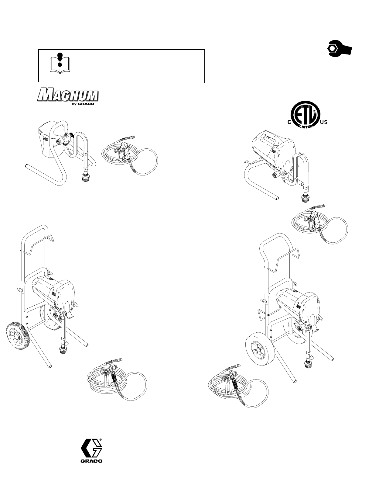
MAGNUM DX
Model 232735
MAGNUM DX, Model 232735, Series A
0.24 gpm (0.91 lpm) stand–mount sprayer, 25 ft (7.6 m)
3/16” hose and SG1t–EF spray gun with reversible spray
tip and guard.
2800 psi (19 MPa, 193 bar) Maximum Working Pressure
MAGNUM XR5
Model 232740
Form No. 309226
Rev. A
This manual contains service
instructions only. See manual
309316 Operators Quick Guide and
309225 Operating Instructions for
complete operating instructions.
9558A
MAGNUM XR7
Model 232745
M
AGNUM XR5, Model 232740, Series A
0.27 gpm (1.02 lpm) stand–mount sprayer, 25 ft (7.6 m)
1/4” hose and SG1–EF spray gun with reversible spray tip
and guard.
3000 psi (21 MPa, 207 bar) Maximum Working Pressure
MAGNUM XR7, Model 232745, Series A
0.31 gpm (1.17 lpm) stand–mount sprayer, 50 ft (15.2 m)
1/4” hose and SG2t metal spray gun with reversible spray
tip and guard.
3000 psi (21 MPa, 207 bar) Maximum Working Pressure
MAGNUM XR9, Model 232750, Series A
0.38 gpm (1.44 lpm) stand–mount sprayer, 50 ft (15.2 m)
1/4” hose and SG3t pro metal spray gun with reversible
spray tip and guard.
3000 psi (21 MPa, 207 bar) Maximum Working Pressure
9558A
9559A
MAGNUM XR9
Model 232750
GRACO INC. P.O. BOX 1441 MINNEAPOLIS, MN 55440–1441
ECOPYRIGHT 2001, GRACO INC.
Graco Inc. is registered to I.S. EN ISO 9001
Page 2

Table of Contents
Warnings 3. . . . . . . . . . . . . . . . . . . . . . . . . . . . . . . . . . . . . . . . . . . . . . . . . . . . . . .
Component Identification and Function 4. . . . . . . . . . . . . . . . . . . . . . . . . . . . .
Pressure Relief Procedure 6. . . . . . . . . . . . . . . . . . . . . . . . . . . . . . . . . . . . . . .
Grounding and Electrical Requirements 6. . . . . . . . . . . . . . . . . . . . . . . . . . . .
General Repair Information 7. . . . . . . . . . . . . . . . . . . . . . . . . . . . . . . . . . . . . . .
Basic Troubleshooting 8. . . . . . . . . . . . . . . . . . . . . . . . . . . . . . . . . . . . . . . . . . .
Advanced Troubleshooting 10. . . . . . . . . . . . . . . . . . . . . . . . . . . . . . . . . . . . . .
List of Kits 17. . . . . . . . . . . . . . . . . . . . . . . . . . . . . . . . . . . . . . . . . . . . . . . . . . . . .
Motor Diagnostics 19. . . . . . . . . . . . . . . . . . . . . . . . . . . . . . . . . . . . . . . . . . . . . .
Control Board Diagnostics 19. . . . . . . . . . . . . . . . . . . . . . . . . . . . . . . . . . . . . . .
Pump Diagnostics 19. . . . . . . . . . . . . . . . . . . . . . . . . . . . . . . . . . . . . . . . . . . . . .
Technical Data 21. . . . . . . . . . . . . . . . . . . . . . . . . . . . . . . . . . . . . . . . . . . . . . . . .
Parts
Model 232735 DX Magnum Sprayer 24. . . . . . . . . . . . . . . . . . . . . . . . . . .
Model 232740 XR5 Magnum Sprayer 24. . . . . . . . . . . . . . . . . . . . . . . . . .
Model 232745 XR7 Magnum Sprayer 26. . . . . . . . . . . . . . . . . . . . . . . . . .
Model 232750 XR9 Magnum Sprayer 28. . . . . . . . . . . . . . . . . . . . . . . . . .
Limited Warranty 30. . . . . . . . . . . . . . . . . . . . . . . . . . . . . . . . . . . . . . . . . . . . . . .
2 309226
Page 3
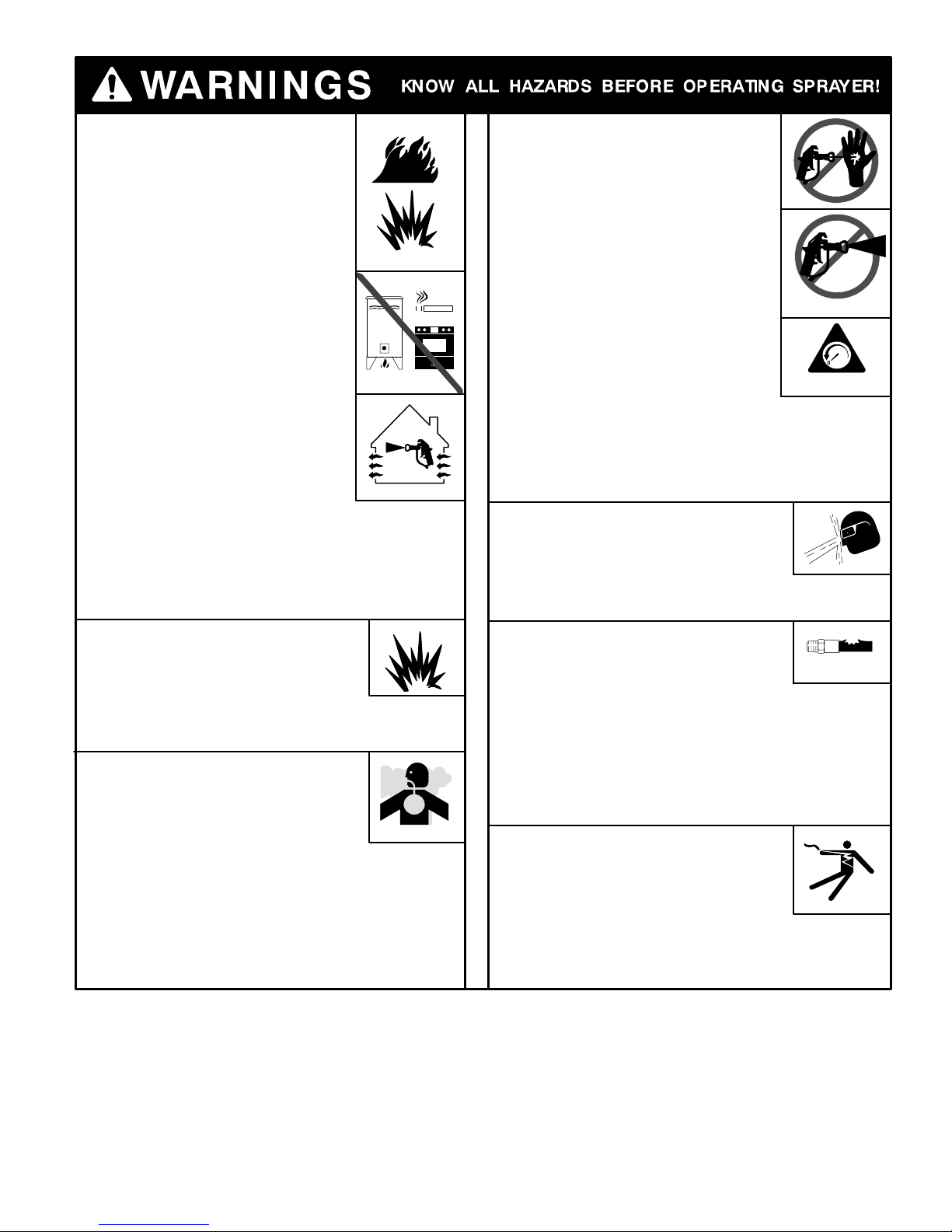
FIRE AND EXPLOSION HAZARD
A Fire and explosion hazard exists
any time you spray or flush flammable fluids.
To help prevent fire or explosion when
spraying flammable fluids
D Be sure sprayer is adequately grounded
through electrical outlet as follows:
– Use only grounded electrical outlets.
– Use only 3-wire extension cords.
– Make sure ground prongs are intact
on sprayer and extension cords.
D Motor in this sprayer is a source of
sparks. Keep sprayer in well-ventilated
area, at least 20 feet (6 meters) away
from gun when spraying or flushing.
D Do not use plastic drop cloths when
spraying or flushing flammable fluids.
D Avoid all ignition sources, such as pilot
lights, cigarettes, and plastic drop cloths
(static arc hazard). Do not plug in or
unplug power cords or turn lights on or
off in spray area.
D Tape wall switches to prevent them from being turned
off or on.
D Do not smoke in spray area.
D Use only M
D Use outdoors or in a well-ventilated area.
EQUIPMENT MISUSE HAZARD
Do not use 1,1,1–trichloroethane, methylene
chloride, other halogenated hydrocarbon
solvents or fluids containing such solvents
in pressurized aluminum equipment such as
this sprayer and gun. Such use could result in
chemical reaction and possible explosion.
TOXIC FLUID HAZARD
Hazardous fluid or toxic fumes can cause
serious injury or death if splashed in eyes
eyes or on skin, inhaled, or swallowed.
To help prevent injury or death from
toxic fluids
D Know specific hazards of fluid you are using; store
hazardous fluid in approved tub; dispose of
hazardous fluid according to all local, state, and
national guidelines.
D Always wear protective eyewear, gloves, clothing, and
respirator as recommended by fluid and solvent
manufacturer.
AGNUM or Graco airless paint hoses.
FLUID INJECTION HAZARD
If high-pressure fluid pierces skin,
the injury might look like “just a cut”
but is a serious wound. Get
immediate medical attention.
To help prevent injection
D Always put trigger safety lever in SAFETY
ON position when not spraying.
D Always shut off power and relieve pressure
when you stop spraying and before you
service or clean sprayer, remove parts, or
repair leaks. See Pressure Relief
Procedure below.
D Do not allow children to use this equipment.
D Keep clear of tip, and never point gun at
yourself or anyone else.
STARTUP HAZARD AFTER THERMAL OVERLOAD
Motor has thermal overload switch to
shut itself down if overheated. To reduce risk of injury
from motor restarting unexpectedly when it cools, always
turn Power switch OFF if motor shuts down.
FLUID SPLASHBACK HAZARD
Wear protective eyewear at all times.
To avoid splashing fluid when spraying
into pail, always aim at inside wall of pail.
Make sure gun is assembled with correct
gasket for fluid being sprayed. See Installing Tip &
Guard in enclosed Operator’s Quick Guide.
PRESSURIZED EQUIPMENT HAZARD
M
AGNUM sprayers are capable of
producing up to 3000 psi (21 MPa, 207 bar)
maximum working pressure. To avoid
component rupture and injury, do not operate sprayer
with components rated less than pressure of sprayer.
Sprayer is equipped with a pressure drain that
automatically relieves overpressure in the event of a fault
condition. This automatic pressure relief may cause
splashing of fluid. Correct fault before you resume spraying.
NOTE: Inadequate flushing and/or dried paint in drain
system may prevent proper overpressure relief.
ELECTRIC SHOCK HAZARD
Gun, hose, and sprayer are grounded
through electrical cord of sprayer.
To help prevent electric shock
D Use only grounded electrical outlets.
D Only use 3-wire extension cords.
D Make sure ground prongs are intact on sprayer and
extension cords.
D Keep electrical connections and inside of shroud dry.
SAFETY ON
pressure
309226 3
Page 4
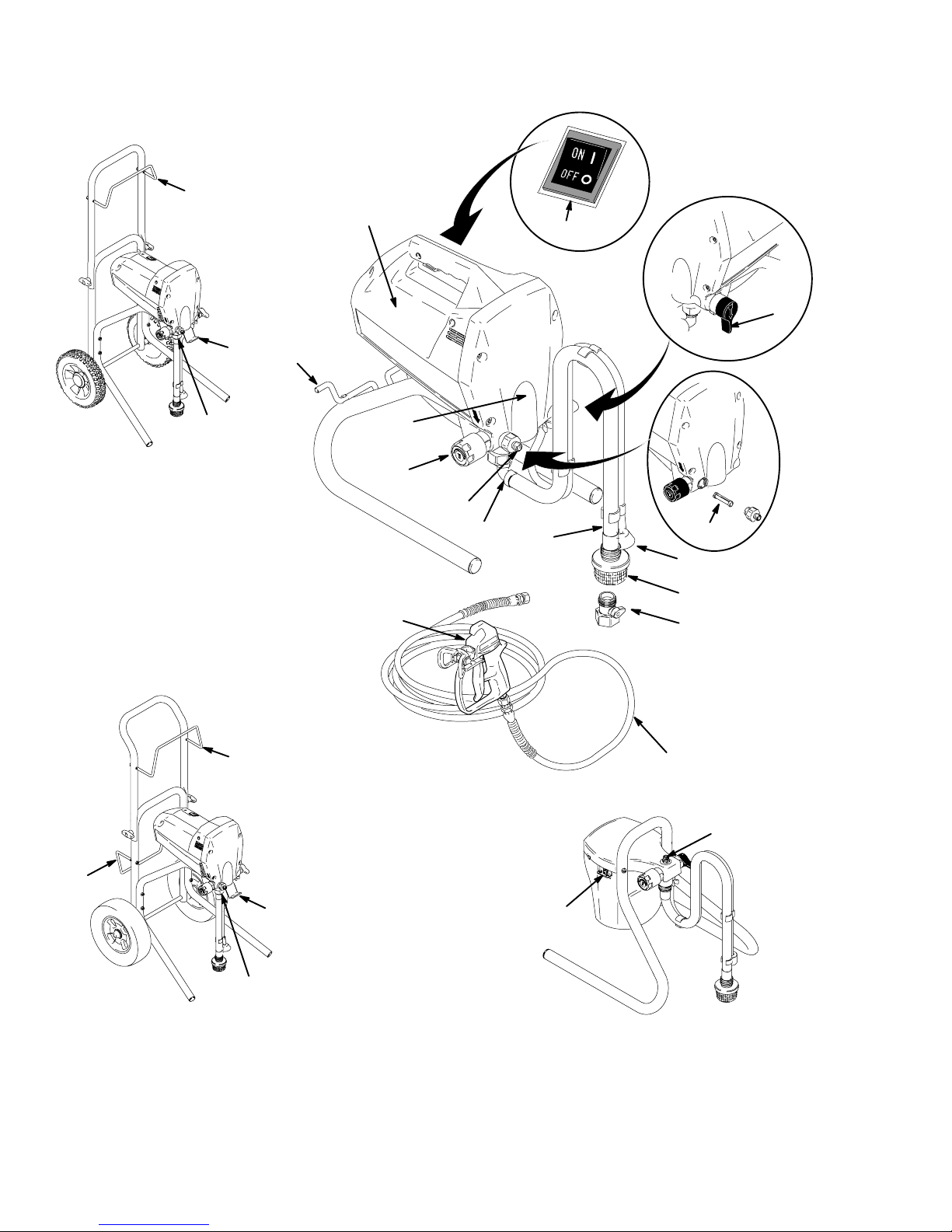
Component Identification and Function
W
A
B
X
N
J
MAGNUM XR7
9558A
K
MAGNUM XR5
W
F
C
D
K
P
G
E
H
L
Y
9560A
M
D
W
X
9559A
K
MAGNUM XR9
4 309226
B
MAGNUM DX
Page 5
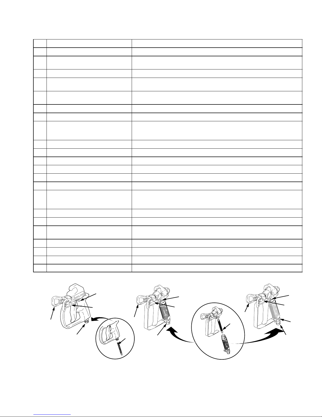
Component Identification and Function
9
A Electric motor (inside of enclosures) Provides mechanical power to pump
B Power switch For manually turning on/off electrical power to motor (“I” is ON / “0” is OFF)
C Pressure Control knob For manually increasing (turn clockwise) and decreasing (turn
counter-clockwise) fluid pressure in pump, hose, and spray gun
D Pump fluid outlet fitting Threaded connection for paint hose
E InstaCleant fluid filter (XR models
only)
F Power-Pistont pump (behind Easy
Access door)
G Suction tube Draws fluid from paint pail into pump
H Prime tube (with diffuser) Drains fluid in system during priming and pressure relief
J Spray/Prime/Drain valve control D Directs pressurized fluid to paint hose in SPRAY position (pointing forward)
K Fluid inlet connection and inlet valve Where suction tube connects to pump and inlet valve
L Inlet screen Prevents debris from entering pump
M Paint hose Transports high-pressure fluid from pump to spray gun
N Cord wrap bracket Stows electrical cord (XR5 model only)
P Airless spray gun Manually-controlled, hand-held on/off device for fluid being sprayed
Q Tip guard Reduces risk of fluid injection injury
R Reversible spray tip D Atomizes fluid being sprayed, forms spray pattern, and controls fluid flow
S Trigger safety lever Prevents accidental triggering of spray gun
T Gun fluid inlet fitting Threaded connection for paint hose
U Smooth Glidet swivel
(SG3 spray gun only)
V Gun fluid filter (in handle) Filters fluid entering spray gun to reduce tip plugging and improve finish
W Hose/Cord wrap bracket Stows paint hose and electrical cord (MAGNUM XR7 and XR9 only)
X Pail hanger For transporting pail by its handle (MAGNUM XR7 and XR9 only)
Y Power Flush attachment (included) Connects garden hose to suction tube for power flushing water-base fluids
D Filters fluid coming out of pump to reduce tip plugging and improve finish
D Self cleans during pressure relief
Pumps and pressurizes fluid and delivers it to paint hose If necessary, Easy
Access door permits quick removal of outlet valve.
D Directs fluid to drain tube in PRIME/DRAIN position (pointing down)
D Automatically relieves system pressure in overpressure situations
according to hole size
D Reverses for unplugging without disassembly
Allows spray gun to swivel without twisting paint hose
S
R
Q
T
SG1–EF Spray Gun
included with
AGNUM DX and XR5
M
V
Q
SG2 Spray Gun
9561A
T
included with
AGNUM XR7
M
S
R
S
R
Q
V
U
T
SG3 Spray Gun
included with
AGNUM XR9
M
309226 5
Page 6
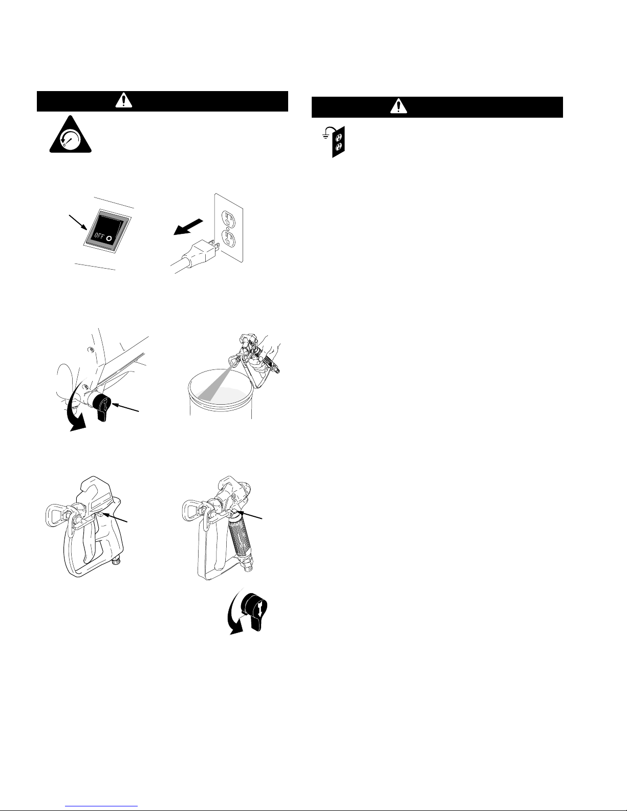
Pressure Relief
Grounding and
Procedure
WARNING
To help prevent injection injuries, follow
this procedure when you stop spraying
and before you service or clean the
psi/MPa/bar
1. Turn Power switch (B) to OFF, and unplug sprayer.
B
2. Turn Spray–Prime/Drain valve (J) to PRIME/
DRAIN to relieve pressure. Trigger gun to relieve
pressure that might be in hose.
sprayer, remove parts, or repair leaks.
9565A
Electrical Requirements
WARNING
This sprayer requires a 120V AC, 60 Hz, 15A
circuit with a grounding receptacle. Never use
an outlet that is not grounded. Do not use the
sprayer if the electrical cord has a damaged ground
prong. Use only an extension cord with an
undamaged, 3-prong plug.
Recommended extension cords for use with this
sprayer are
D 25 ft (7.6 m) 18 AWG
D 50 ft (15.2 m) 16 AWG
D 100 ft (30.5 m) 14 AWG
D 150 ft (45.7 m) 12 AWG
NOTE: Smaller-gauge or longer extension cords may
reduce sprayer performance.
J
3. Put trigger safety (S) in SAFETY ON position.
SG1–EF
S
NOTE: Leave Spray–Prime/Drain
valve in the PRIME/DRAIN position
until you are ready to spray again.
If you suspect that the spray tip or hose is completely
clogged or that pressure has not been fully relieved
after following the steps above, VERY SLOWLY loos-
en the tip guard retaining nut or hose end coupling to
relieve pressure gradually. Then loosen it completely.
Then clear the tip or hose obstruction.
SG2 / SG3
9565A
S
9565A
6 309226
Page 7
General Repair Information
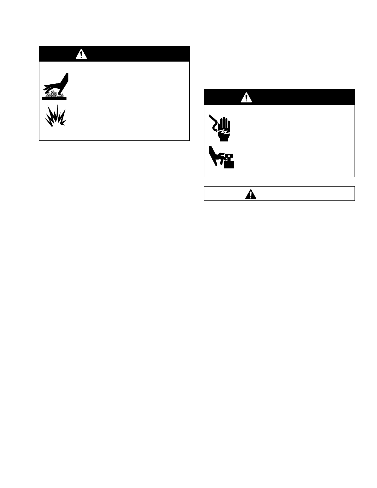
WARNING
HOT SURFACES HAZARD
EXPLOSION HAZARD
Motor and drive housing may be very hot
during operation and could burn skin if
touched.
Flammable materials spilled on hot, bare
motor could cause fire or explosion.
Have enclosures in place during
operation to reduce risk of burns, fire, or
explosion.
D Keep all screws, nuts, washers, gaskets, and
electrical fittings that you remove during repair
procedures. These parts are not normally provided
with replacement assemblies.
Do not operate the sprayer without the enclosure.
Replace if damaged. Enclosures direct cooling air
around the motor to prevent overheating. They also
reduce the risk of burns, fire or explosion. Read the
following WARNING.
WARNING
ELECTRIC SHOCK HAZARD
MOVING PARTS HAZARD
To reduce risk of serious injury, including
electric shock, do not touch moving or
electrical parts with fingers or tools while
testing repair. Unplug sprayer when power
is not required for testing. Install all
covers, gaskets, screws, and washers
before you operate sprayer.
CAUTION
D Test repairs after problems are corrected.
D If the sprayer does not operate properly, review
the repair procedure to verify that you did it correctly. See Troubleshooting on page 8 and
Advanced Troubleshooting on page 10.
D Overspray may build up in the air passages.
Remove any overspray and residue from the air
passages and openings in the enclosures whenever
you service the sprayer.
Do not run sprayer dry for more than 30 seconds.
Doing so could damage pump packings.
Protect the internal drive parts of this sprayer
from water. Openings in the enclosures allow for air
cooling of the mechanical parts and electronics
inside. If water gets into these openings, the sprayer
could malfunction or be permanently damaged.
Prevent pump corrosion and damage from freezing. Never leave water or water-base paint in
the sprayer when it is not in use in cold weather.
Freezing fluids can seriously damage the sprayer.
Store the sprayer with mineral spirits/paint thinner or
Graco Pump Armor to protect equipment during
storage.
309226 7
Page 8
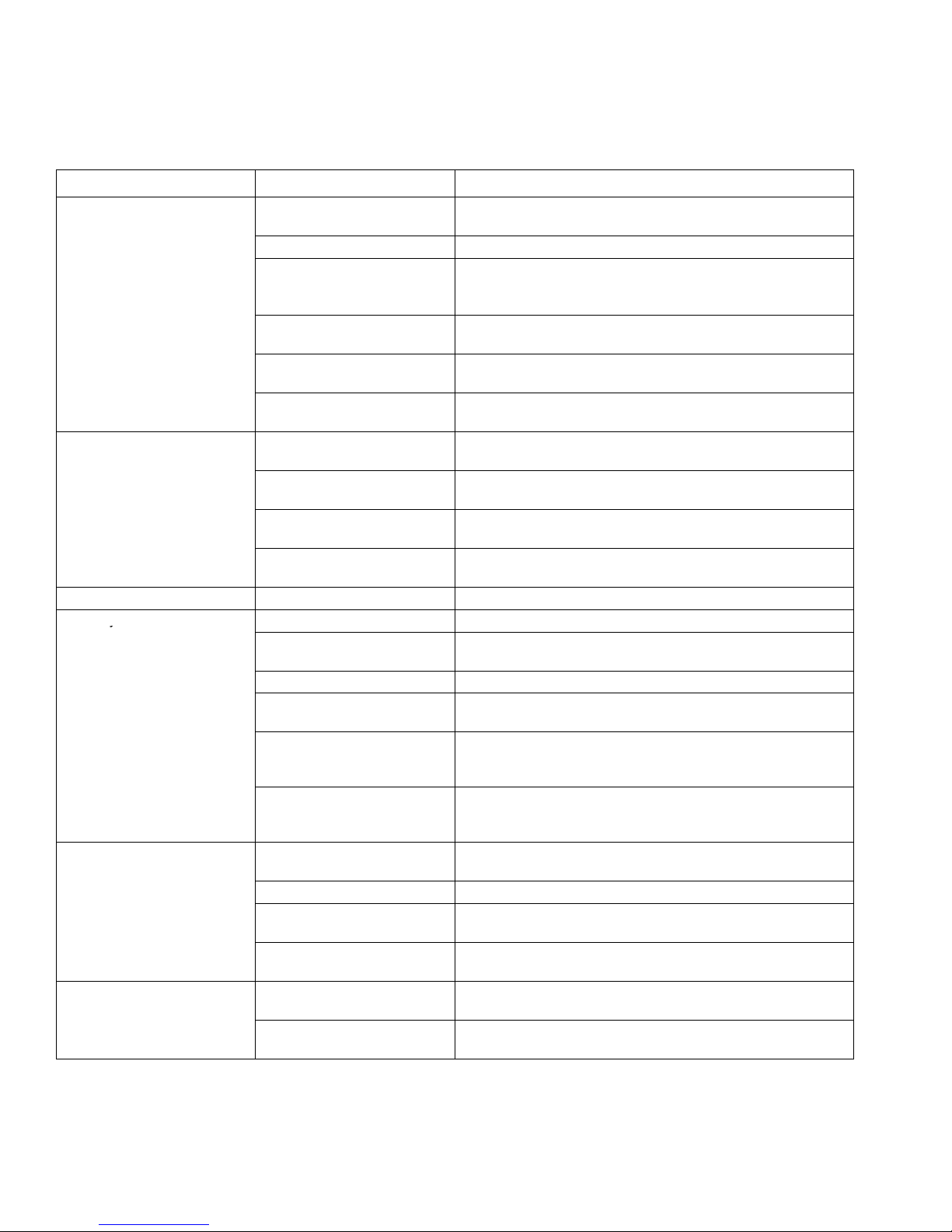
Basic Troubleshooting
does not cycle
does not cycle
y
The following troubleshooting guidelines from the Operating Instructions manual are included here as preemptive
measures against Advanced Troubleshooting on page 10.
PROBLEM CAUSE SOLUTION
Power switch is on and
sprayer is plugged in, but
motor does not run, and pump
.
.
Pump does not prime. Spray–Prime/Drain valve is in
Spray gun stopped spraying. Spray tip is plugged. Unplug spray tip. See manual 309225 Operating Instructions.
Pump cycles but does not
build up pressure.
Pump cycles, but paint only
dribbles or spurts when spray
gun is triggered.
Spray pattern is inconsistent
or is leaving stripes.
Pressure is set at zero
pressure.
Motor or control is damaged. See Motor Does Not Operate on page 10.
Electrical outlet is not
providing power.
Extension cord is damaged. Replace extension cord. See Grounding and Electrical
Sprayer electrical cord is
damaged.
Paint is frozen or hardened in
pump.
SPRAY position.
Inlet screen is clogged, or
suction tube is not immersed.
Balls in check valve are stuck,
or check valves are damaged.
Suction tube is leaking. Tighten suction tube connection (K). Inspect for other cracks
Pump is not primed. Prime pump.
Inlet screen is clogged, or
suction tube is not immersed.
Paint pail is empty. Refill paint pail, and reprime sprayer.
Suction tube is leaking. Tighten suction tube connection (K). Inspect for other cracks
Pump check valves are dirty
or damaged. (Usually only
one valve)
Spray–Prime/Drain valve is
worn or obstructed with debris
Pressure is set too low. Slowly turn Pressure Control knob (C) clockwise to Increase
Spray tip is plugged. Unplug spray tip. See manual 309225 Operating Instructions.
InstaClean fluid filter is
clogged. (XR models only)
Spray gun fluid filter is
clogged.
Pressure is set too low. Turn Pressure Control knob (C) clockwise to increase
Spray tip is worn beyond
capability of sprayer.
Turn Pressure Control knob (C) clockwise to increase
pressure setting.
D Try a different outlet, or plug in something that you know is
working to test outlet.
D Reset building circuit breaker, or replace fuse.
Requirements on page 6.
Check for broken insulation or wires. Replace electrical cord if
damaged.
See Motor Does Not Operate on page 10.
Turn Spray–Prime/Drain valve (J) to PRIME/DRAIN position
(pointing down).
Clean debris off inlet screen (L), and make sure suction tube
(G) is at bottom of paint pail.
Clean or replace check valves. See Pump Service on page
20. Do not store in water.
or vacuum leaks.
Clean debris off inlet screen (L), and make sure suction tube
(G) is at bottom of paint pail.
or vacuum leaks.
Clean or replace check valves. See Pump Service on page
20.
Check Spray–Prime/Drain valve for debris trapped on seat
and worn parts. Torque to 185 in-lb (21 NSm). Replace if parts
are worn.
pressure setting to check if sprayer develops more pressure.
Clean or replace InstaClean fluid filter (E).
Clean or replace spray gun fluid filter (V).
pressure.
Replace spray tip.
8 309226
Page 9

Basic Troubleshooting
g
intermittentl
NOTE: This is a thermal
WARNINGS section on
OR
PROBLEM CAUSE SOLUTION
Pressure is set at maximum,
but cannot achieve a good
spray pattern.
Motor is hot and runs
y.
NOTE: This is a thermal
overload condition. Motor
automatically shuts off due to
excessive heat.
See Startup Hazard After
Thermal Overload in the
page 3. Damage can occur if
cause is not corrected.
Building circuit breaker opens
after sprayer operates for 5 to
10 minutes.
OR
Building circuit breaker opens
as soon as sprayer is plugged
into outlet, and sprayer is
turned on.
Fan pattern varies
dramatically while spraying
OR
Sprayer does not turn on
promptly when resuming
spraying.
Cannot trigger spray gun. Spray gun trigger safety lever
Spray comes out of spray gun
in two thick streams.
Paint is coming out of
pressure control switch.
Spray–Prime/Drain valve
actuates automatically,
relieving pressure through
drain tube.
Paint leaks down outside of
pump.
Spray tip is too big for
sprayer.
Spray tip is worn beyond
capability of sprayer.
Extension cord is too long or
not a heavy enough gauge.
Spray gun fluid filter is
clogged.
InstaClean fluid filter is
clogged. (XR models only)
Inlet screen is clogged. Clean debris off inlet screen (L).
Pump valves are worn. See Output is Low or Fluctuating on page 13.
Vent holes in enclosures are
p
plugged, or sprayer is
covered.
Extension cord is too long or
not a heavy enough gauge.
Unregulated electrical
generator being used has
excessive voltage.
Sprayer was operated at high
pressure with very small tip,
which causes frequent motor
starts and excessive heat
build up.
Too many appliances are
plugged in on same circuit.
Sprayer electrical cord is
damaged.
Pressure control switch is
worn and causing excessive
pressure variation.
is in SAFETY ON position.
Reversible spray tip is in
UNCLOG position.
Pressure control switch is
worn.
System is overpressurizing. See Excessive Pressure is Building Up on page 16.
Pump packings are worn. Replace pump packings. See Pump Service on page20.
p
Select a smaller spray tip.
Replace spray tip.
Replace extension cord. See Grounding and Electrical
Requirements on page 6.
Clean or replace spray gun fluid filter (V).
Clean or replace InstaClean fluid filter (E).
Keep vent holes clear of obstructions and overspray, and keep
p
sprayer open to air.
Replace extension cord. See Grounding and Electrical
Requirements on page 6.
Use electrical generator with a proper voltage regulator.
Sprayer requires a 120V AC, 60 Hz, 1500-Watt generator.
Decrease pressure setting or increase tip size.
Free up circuit (unplug things), or use a less busy circuit.
Check for broken insulation or wires. Replace electrical cord if
damaged.
Replace Pressure Control knob using Pressure Control
Switch Kit 244266 for DX models or 244267 for XR models.
Rotate trigger safety lever (S) to SAFETY OFF position.
Rotate arrow-shaped handle on spray tip so it points forward in
SPRAY position.
Replace Pressure Control knob using Pressure Control
Switch Kit 244266 for DX models or 244267 for XR models.
p
309226 9
Page 10

Advanced Troubleshooting
t
See Electric Shock Hazard on
page 7.
See Pressure Relief
Procedure on page 6.
NOTE: See Basic Troubleshooting on page 8 for the problems that are more easily remedied.
General Problem: Motor Does Not Operate
SPECIFIC PROBLEM CAUSE SOLUTION
Power switch is on and
p
sprayer is plugged in, bu
pump does not cycle.
Basic Mechanical
Problems
Basic Electrical Problems Motor is overheated. Allow to cool for 30 minutes. Retry.
p
See Basic Troubleshooting page 8.
Paint is frozen or hardened in pump. Unplug sprayer from electrical outlet.
NOTE: If frozen, do not try to start sprayer
until completely thawed, or damage to motor,
control board, and/or drivetrain may occur.
Make sure power switch (B) is OFF. Place
sprayer in warm area for several hours, then
plug in and turn on. Slowly increase pressure
setting to see if motor starts.
If paint hardened in sprayer, replace pump
packings and remove all residue from valves.
See Pump Service on page20.
Motor is damaged. Remove gear, and try to rotate motor shaft by
hand. See Motor Diagnostics on page 19. If
shaft will not turn, replace motor using Motor
Kit 245080 for DX models or 243236 for XR
models.
Yoke is broken, because pump is locked up by
dried paint or worn packings. (XR models only)
Electrical outlet is damaged. Reset building circuit breaker or replace
Control board leads are improperly fastened or
improperly mated.
Motor brushes are worn.
NOTE: Brushes do not wear at the same rate on
both sides of motor. Check both brushes.
Motor armature commutator is damaged. Check for burn spots, gouges and extreme
Repair as necessary or replace using
Gear/Yoke Repair Kit 243230.
building fuse. Try another outlet.
Check electric supply with volt meter. Meter
must read 85 to 130V AC. If voltage is too
high, do not plug sprayer in until outlet is
corrected.
Replace any loose terminals. Make sure all
leads and harnesses are firmly connected.
Check pressure control harness connection on
front side of drive housing.
Clean control board terminals. Securely
reconnect leads.
Check length of brushes. Brush length must
be 0.25 in. (6.4 mm) minimum. If brushes are
worn, replace motor using Motor Kit 245080
for DX models or 243236 for XR models.
roughness. Have motor shop resurface
commutator if possible, or replace motor using
Motor Kit 245080 for DX models or 243236 for
XR models.
10 309226
Page 11

Advanced Troubleshooting
General Problem: Motor Does Not Operate (continued)
SPECIFIC PROBLEM CAUSE SOLUTION
Basic Electrical Problems
(Continued)
Motor armature is shorting. Check for shorts using armature tester (growler), or perform
spin test (see Motor Diagnostics on page 19). If shorts are
evident, replace motor using Motor Kit 245080 for DX
models or 243236 for XR models.
Sprayer Wiring Problems
NOTE: Remove right
enclosure mounting
screws, and pull right
enclosure away from drive
housing. Take care to not
pull on the leads from
the electrical cord and
the Power switch (B).
Control board is damaged.
CAUTION: Do not perform control
board diagnostics until you have
determined that the armature is good.
A bad motor armature can burn out a
good control board.
Sprayer electrical cord is damaged. Unplug sprayer electrical cord. Disconnect black electrical
Sprayer power switch (B) is damaged. Unplug sprayer electrical cord. Disconnect black control
Thermal overload cutoff switch is
damaged.
See Startup Hazard After Thermal
Overload in the WARNINGS section
on page 3.
Terminals are damaged or loose. Replace any damaged terminals, and make sure all
See Control Board Diagnostics on page 19, and replace
control board if damaged using Control Board Kit 245079
for DX models, 243228 for XR5 and XR7 models, or
243229 for XR9 models.
cord wire at Power switch (B), and unplug in-line connection
of white electrical cord wire. Plug in electrical cord, and test
voltage between black and white electrical cord wires.
Meter must read 85 to130V AC.
Replace electrical cord if no voltage.
board wire at Power switch (B), and unplug in-line
connection of white electrical cord wire. Plug in electrical
cord, turn Power switch ON, and test voltage between open
terminal of Power switch and white electrical cord wire.
Meter must read 85 to130V AC.
Replace Power switch (B) if no voltage.
Unplug sprayer electrical cord. Remove motor harness from
control card, and check for continuity between yellow leads
of motor harness. If thermal relief switch is open (no
continuity), allow motor to cool. If switch remains open after
motor cools, replace motor using Motor Kit 245080 for DX
models or 243236 for XR models.
If thermal relief switch closes after motor cools, find and
correct cause of overheating.
terminal connections are tight.
309226 11
Page 12

Advanced Troubleshooting
g
General Problem: Circuit Breaker is Tripping
SPECIFIC PROBLEM CAUSE SOLUTION
Building circuit breaker opens
as soon as sprayer is turned on.
Sprayer electrical wiring is pinched, or insulation
is damaged.
Wires between pressure control switch and
control board are pinched.
Motor armature is shorting. Check for shorts using armature tester
Repair or replace any damaged wiring or
terminals. Securely reconnect all wires.
(growler), or perform spin test (see Motor
Diagnostics on page 19). If shorts are
evident, replace motor using Motor Kit
245080 for DX models or 243236 for XR
models.
Building circuit breaker opens
as soon as sprayer is plugged
into outlet, and sprayer is NOT
turned on.
NOTE: Remove right
enclosure mounting screws,
and pull right enclosure away
from drive housing. Take care
to not pull on the leads from
the electrical cord and the
Power switch (B).
Control board is damaged.
CAUTION: Do not perform control board
diagnostics until you have determined that the
armature is good. A bad motor armature can burn
out a good control board.
Sprayer electrical cord is damaged. Unplug sprayer electrical cord. Disconnect
Sprayer Power switch (B) is damaged. Unplug sprayer electrical cord, and
See also “Basic Electrical Problems” on page 10 and “Sprayer Wiring Problems” on page 11.
See Control Board Diagnostics on page
19, and replace control board if damaged
using Control Board Kit 245079 for DX
models, 243228 for XR5 and XR7 models, or
243229 for XR9 models.
black electrical cord wire at Power switch (B),
and unplug in-line connection of white
electrical cord wire. Plug in electrical cord,
and test voltage between black and white
electrical cord wires. Meter must read
85 to130V AC.
Replace electrical cord if no voltage.
disconnect wires from Power switch (B).
Check resistance of switch with ohmmeter.
Reading must be infinity with Power switch
OFF, and zero with Power switch ON.
Replace Power switch if damaged.
12 309226
Page 13

Advanced Troubleshooting
General Problem: Motor Operation is Erratic
SPECIFIC PROBLEM CAUSE SOLUTION
Sprayer quits after running for 5 to 10 minutes. Electrical outlet is damaged or
supplying the wrong voltage.
See also “Basic Electrical Problems” on page 10 and “Sprayer Wiring
Problems” on page 11.
Motor is hot and runs intermittently.
NOTE: This is a thermal overload condition.
Motor automatically shuts off due to excessive
heat.
See Startup Hazard After Thermal Overload
in the WARNINGS section on page 3.
Damage can occur if cause is not corrected.
See Basic Troubleshooting page 9.
General Problem: Output is Low or Fluctuating
Reset building circuit breaker or
replace building fuse. Try another
outlet.
Check electric supply with volt meter.
Meter must read 85 to 130V AC. If
voltage is too high, do not use outlet
until corrected.
pp
SPECIFIC PROBLEM CAUSE SOLUTION
Pump cycles, but output is low
or surging.
See Basic Troubleshooting page 8.
Pump valves are worn or obstructed by debris. Check for worn pump valves as follows:
Prime sprayer with paint. Trigger spray gun
momentarily. When spray gun trigger is
released, pump should cycle momentarily
and stop. If pump continues to cycle, pump
valves may be worn or obstructed.
See Pump Service on page 20.
Spray–Prime/Drain valve is leaking. Check Spray–Prime/Drain valve for debris
trapped on seat and for worn parts. Torque to
185 in-lb (21 NSm). Replace if parts are worn
using Spray–Prime/Drain Valve Kit 235014.
Voltage from electrical outlet is too low. Low
voltages reduce sprayer performance.
Extension cord is too long or not a heavy enough
gauge.
Leads from motor to control board are damaged,
loose, or overheated.
Check voltage of outlet. Meter must read
85 to 130V AC.
Reset building circuit breaker or replace
building fuse.
Repair electrical outlet or try another outlet.
Replace extension cord.
See Grounding and Electrical
Requirements on page 6.
Be sure terminals are centered and firmly
connected. Inspect wiring insulation and
terminals for signs of overheating, and
replace any loose terminals or damaged
wiring. Securely reconnect terminals.
309226 13
Page 14

Advanced Troubleshooting
General Problem: Output is Low or Fluctuating
SPECIFIC PROBLEM CAUSE SOLUTION
Motor brushes are worn.
NOTE: Brushes do not wear at the same rate on
both sides of motor. Check both brushes.
Motor brush springs are broken. If springs are broken, replace motor using
Motor brushes are binding in brush holders. Clean brush holders, remove carbon dust
Motor stops before sprayer reaches correct
pressure (stall pressure is too low).
Check length of brushes. Brush length must
be 0.25 in. (6.4 mm) minimum. If brushes
are worn, replace motor using Motor Kit
245080 for DX models or 243236 for XR
models.
Motor Kit 245080 for DX models or 243236
for XR models.
with small cleaning brush.
Replace Pressure Control knob using
Pressure Control Switch Kit 244266 for DX
models or 244267 for XR models.
General Problem: Output is Low or Fluctuating
SPECIFIC PROBLEM CAUSE SOLUTION
Motor armature is shorting. Check for shorts using armature tester
(growler), or perform spin test (see Motor
Diagnostics on page 19). If shorts are
evident, replace motor using Motor Kit
245080 for DX models or 243236 for XR
models.
Control board is damaged.
CAUTION: Do not perform control board
diagnostics until you have determined that the
armature is good. A bad motor armature can burn
out a good control board.
See Control Board Diagnostics on page
19, and if damaged, replace control board
using Control Board Kit 245079 for DX
models, 243228 for XR5 and XR7 models, or
243229 for XR9 models.
General Problem: Output is Low or Fluctuating (continued)
SPECIFIC PROBLEM CAUSE SOLUTION
Motor runs and pump
cycles, but pressure does
not build up.
Intake valve ball or outlet valve ball is not
seating properly.
Pump packings are worn or damaged. Check for leaking around throat packing nut.
Spray–Prime/Drain valve is leaking.
Remove and clean valves, and check balls and
seats for nicks; replace if necessary. Strain paint
before spraying to remove particles that could clog
pump.
See Pump Service on page 20.
Replace pump packings if there are leaks.
See Pump Service on page 20.
Check Spray–Prime/Drain valve for debris trapped
on seat and for worn parts. Torque to 185 in-lb
(21 NSm). If parts are worn, replace valve using
Spray–Prime/Drain Valve Kit 235014.
14 309226
Page 15

Advanced Troubleshooting
t
General Problem: Output is Low or Fluctuating (continued)
SPECIFIC PROBLEM CAUSE SOLUTION
Spray pattern has
variations, pressure
fluctuates excessively, or
motor runs very slowly.
Leads from motor to control board are
damaged, loose, or overheated.
Pressure control switch leads are pinched
between pump and drive housing or between
front cover and drive housing.
Control board is damaged.
CAUTION: Do not perform control board
diagnostics until you have determined that the
armature is good. A bad motor armature can
burn out a good control board.
Pressure control switch is damaged or worn
out.
Be sure terminals are centered and firmly
connected. Inspect wiring insulation and terminals
for signs of overheating, and replace any loose
terminals or damaged wiring. Securely reconnect
terminals.
Make sure pressure control harness is routed
behind pump, through retention clip, and
connected to control board connector at back of
drive housing (connected with tab to the right).
See Control Board Diagnostics on page 19. If
damaged, replace control board using Control
Board Kit 245079 for DX models, 243228 for XR5
and XR7 models, or 243229 for XR9 models.
Replace pressure control switch using Pressure
Control Switch Kit 244266 for DX models or
244267 for XR models.
General Problem: There is No Output
SPECIFIC PROBLEM CAUSE SOLUTION
Power switch is on and
p
sprayer is plugged in, bu
pump does not cycle.
Motor runs, but pump does not
cycle.
Motor does not run. Water or paint entered pressure control
p
See Basic Troubleshooting page 8.
Gear and/or yoke are damaged. Replace gear and yoke using Gear/Yoke Repair
Kit 243230.
Clean out and/or dry out, and retry. Replace if
switch or shorted control board.
necessary using Pressure Control Switch Kit
244266 for DX models or 244267 for XR models.
309226 15
Page 16

Advanced Troubleshooting
General Problem: Excessive Pressure is Building Up
SPECIFIC PROBLEM CAUSE SOLUTION
Spray–Prime/Drain valve
actuates automatically,
relieving pressure
through drain tube.
Pressure control switch is worn. Replace pressure control switch using Pressure
Control Switch Kit 244266 for DX models or
244267 for XR models.
Water or paint entered pressure control switch
or shorted control board.
Control board has failed. See Control Board Diagnostics on page 19, and
Clean out and/or dry out, and retry. Replace if
necessary using Pressure Control Switch Kit
244266 for DX models or 244267 for XR models.
replace control board if damaged using Control
Board Kit 245079 for DX models, 243228 for XR5
and XR7 models, or 243229 for XR9 models.
16 309226
Page 17

List of Kits
Kit Number Models/Series Kit Description
235014 XR/All Spray–Prime/Drain Valve
243082 XR/All Inlet Strainer (for inlet of suction tube)
243090 XR/All Pump Repair (pump packing module)
245077 DX Pump Inlet Valve Module
243093 XR/All Pump Inlet Valve Module (1/2” NPT bottom port)
245070 XR/All Pump Inlet Valve Module (intergral hose barb)
195750 XR5/All Suction Tube (inlet valve with 1/2” NPT bottom port;
115628 plastic elbow)
197607 XR5/All Suction Tube (inlet valve with intergral hose barb; no el-
bow)
195883 XR7 & XR9/All Suction Tube (inlet valve with 1/2” NPT bottom port)
197608 XR7 & XR9/All Suction Tube (inlet valve with intergral hose barb
245076 DX Pump Outlet Valve Module
243094 XR/All Pump Outlet Valve Module
244035 DX Drain Tube Diffuser
243096 XR/All Drain Tube Diffuser
244266 DX & XR5/A Pressure Control Switch
244267 XR5/B & C;
XR7 & XR9/All
245079 DX Control Board
243228 XR5 & XR7/All Control Board
243229 XR9/All Control Board
XR5/XR7/XR9 Pressure Control Switch
(continued)
309226 17
Page 18

List of Kits
Kit Number Models/Series Kit Description
245109 XR/All Combo Kit (Motor/Gear/Front Cover for 3/8” bronze bear-
ing configuration)
243231 XR/All Fan/Shroud/Brace
243230 XR5/A & B;
XR7/A; XR9/A
245062 XR5/C; XR7/B;
XR9/B
243237 XR5/A & B;
XR7A; XR9A
245064 XR5/C; XR7B;
XR9B
243236 XR5/ A & B;
XR7/A; XR9/A
245063 XR5/C; XR7/B;
XR9/B
243232 XR5/All Enclosure (includes both sides, labels, and screws)
243234 XR7 & XR9/All Enclosure (includes both sides, labels, and screws)
245078 DX Pump Repair
245080 DX Motor Repair
245078 DX DX Pump Repair
243533 XR/All XR Pump Replacement (complete pump*)
10mm Shaft Gear/Yoke/Guides (ball bearing equipped
cover and motor castings)
3/8” Shaft Gear/Yoke/Guides (bronze bearing equipped
cover and motor castings)
Front Cover (10mm ball bearing)
Front Cover (3/8” bronze bearing)
Motor/Drive Housing (10mm ball bearing motor casting)
Motor/Drive Housing (3/8” bronze bearing motor casting)
* Does not include Pressure Control Switch 244267 . Re-use
pressure control switch from pump being replaced, or order
separately.
18 309226
Page 19

Motor Diagnostics
Check for electrical continuity in the motor armature, windings, and brush as follows:
If Motor Diagnostics reveal a damaged motor, or if either of the motor brushes are shorter than 1/4 in. (6.4 mm),
or if the motor shaft cannot turn, replace the motor using Motor Kit 245080 for DX models or 243236 for XR models.
See Electric Shock Hazard on
page 7.
See Pressure Relief
Procedure
Setup
1. Unplug electrical cord, and relieve pressure.
2. Remove right enclosure, and disconnect motor
harness from control board.
3. Remove fan brace.
4. Remove the four cover screws and front cover.
5. Remove yoke and guide rods, and remove gear.
on page 6.
Armature Short Circuit Test (Spin Test) (XR Models
only)
Quickly turn motor fan by hand. If there are no electrical shorts, fan coasts two or three revolutions before
stopping. If fan does not spin freely, armature is
shorted. Replace motor using Motor Kit 245080 for
DX models or 243236 for XR models.
Armature, Brushes, and Motor Wiring Open
Circuit Test (Continuity) (XR models only)
1. Connect red and black motor leads together with
test lead. Turn motor fan by hand at about two
revolutions per second.
2. If there is uneven resistance or no resistance,
replace motor using Motor Kit 245080 for DX
models or 243236 for XR models.
Control Board Diagnostics
Check for a damaged control board or pressure control switch as follows:
See Electric Shock Hazard on
page 7.
See Pressure Relief
Procedure
1. Unplug electrical cord, and relieve pressure.
2. Remove the four cover screws and front cover.
3. Remove yoke and guide rods, and remove gear.
4. Remove pressure control harness from control
board. Using fingernail or tip of small, flat-
blade screwdriver, press tab on right side
connector to release.
on page 6.
5. Attach to the control board a harness from a
pressure switch that you know is functioning
correctly.
NOTE: Pressure control switch does not have to
be installed in pump.
6. Turn pressure control adjustment knob to maximum pressure setting.
7. Plug electrical cord into 120V AC receptacle, and
turn Power switch (B) ON.
D If motor runs, replace pressure switch.
D If motor does not run, replace control board
and repeat test using Control Board Kit
245079 for DX models, 243228 for XR5 and
XR7 models, or 243229 for XR9 models.
309226 19
Page 20

Pump Diagnostics
All Models
CAUTION
When repairing or cleaning the pump, never submerge the pump in water or allow fluid to enter the pressure control.
When the pump packings wear, paint begins to leak down the outside of the pump. Replace the pump packings at
the first sign of leaking, or additional damage could occur. Use pump repair kit 245078 for DX models or 243090 for
XR models.
Pump Service
All Models
CAUTION
When repairing or cleaning the pump, never submerge the pump in water or allow fluid to enter the pressure control.
If the sprayer continues to cycle (motor and pump run) when the spray gun trigger is released, or if performance is
poor even with new spray tips and clean filters, the pump inlet or outlet valve my be obstructed or worn. If a pump
valve is worn, replace it.
Pump Service Kits
Model Description Kit
DX All 245078
XR Inlet Valves – 1/2” NPT bottom port 245093
XR Inlet Valves – integral hose barb 245070
XR Outlet Valves – All 243094
20 309226
Page 21

Technical Data
MAGNUM DX MAGNUM XR5 MAGNUM XR7 MAGNUM XR9
Working pressure
range
Electric motor
(open-frame,
permanent magnet DC)
Operating horsepower 3/8
Maximum delivery (with
tip)
Paint hose 25 ft (7.6 m) x 3/16 in.
Maximum tip hole size 0.015 in. (0.38 mm)
Weight, sprayer only 13 lb (6 kg)
Weight, sprayer, hose,
& gun
Dimensions 14.9 in. (37.8 cm) L
Power cord 16 AWG, 3 wire, 6 ft
Pump inlet fitting 3/4 in. internal thread (standard garden hose thread)
0 to 2800 psi
(0 to 19 MPa, 0 to 193
bar)
6.5 Amp
0.24 gpm (.91 lpm)
16 lb (7.25 kg)
15.0 in. (38.1 cm) W
15.6 in. (39.6cm) H
(1.8 m)
0 to 3000 psi
(0 to 21 MPa, 0 to 207
bar)
5.8 Amp
5/8
0.27 gpm (1.02 lpm)
25 ft (7.6 m) x 1/4 in.
0.015 in. (0.38 mm)
21 lb (10 kg)
24 lb (11 kg)
13.75 in. (34.9 cm) L
11 in. (27.9 cm) W
17 in. (43.2 cm) H
16 AWG, 3 wire, 6 ft
(1.8 m
0 to 3000 psi
(0 to 21 MPa, 0 to 207
bar)
5.8 Amp 4.9 Amp
3/4 7/8
0.31 gpm (1.17 lpm) 0.38 gpm (1.44 lpm)
50 ft (15.2 m) x 1/4 in. 50 ft (15.2 m) x 1/4 in.
0.017 in. (0.43 mm) 0.019 in. (0.48 mm)
31 lb (14 kg) 35 lb (16 kg)
36 lb (17 kg) 40 lb (18 kg)
19.5 in. (49.5 cm) L
17.25 in. (43.8 cm) W
40.75 in. (103.5 cm) H
Height with folded
handle is
26 in. (66 cm)
16 AWG, 3 wire, 6 ft
(1.8 m)
0 to 3000 psi
(0 to 21 MPa, 0 to 207
bar)
19.5 in. (49.5 cm) L
19 in. (48.3 cm) W
40 in. (101.6 cm) H
Height with folded
handle is
26 in. (66 cm)
16 AWG, 3 wire, 10 ft
(3 m)
Fluid outlet fitting 1/4 npsm external thread
Inlet screen on suction
tube
Wetted parts, pump &
hose
Wetted parts, gun SG1–EF: plated steel, nylon, aluminum, tungsten carbide, stainless steel, brass, viton
Generator requirement 1500 Watt minimum
Electrical power
requirement
Storage temperature
range * {
Operating temperature
range **
stainless steel, brass, leather, ultra-high molecular weight polyethylene (UHMWPE), carbide, nylon,
PVC, zinc-aluminum alloy, polypropylene
SG2 / SG3: aluminum, brass, carbide, nylon, plated steel, stainless steel, UHMWPE, zinc
14 mesh (1300 micron)
120V AC, 60 Hz, 1 phase, 15A
–30_ to 160_ F (–35_ to 71_ C)
40_ to 115_ F (4_ to 46_ C)
* When pump is stored with non-freezing fluid. Pump damage will occur if water or latex paint freezes in pump.
{ Damage to plastic parts may result if impact occurs in low-temperature conditions.
* * Changes in paint viscosity at very low or very high temperatures can affect sprayer performance.
309226 21
Page 22

Model 232735 DX Sprayer
50
57
52
23
Parts
54
55
42
44
45
53
31
13
4
58
40
51
12
7
5
13
2
3
59
1
56
22 309226
Page 23

Model 232735 DX Sprayer
Parts
Ref.
No. Part No. Description Qty.
1 196569 FRAME 1
2 243082 STRAINER 1
3 244035 DEFLECTOR, barbed 1
4 195400 CLIP, spring 2
5 196582 TUBE, suction 1
7 196586 COVER, switch 1
12 195084 TUBE, drain 1
13 115489 CLAMP, drain tube 2
23 244266 KIT, pressure switch, repair 1
31 235014 KIT, valve, repair 1
40 196566 HOUSING, pump 1
42 196567 COVER, housing 1
Ref.
No. Part No. Description Qty.
44 196577 GEAR, eccentric 1
45 196579 GEAR, combination 1
50 245078 KIT, pump repair 1
51 245079 KIT, control board 1
52 245080 KIT, motor, repair 1
53 245076 KIT, outlet valve 1
54 245077 KIT, inlet valve 1
55 116295 CLAMP, spring, .88 diameter 1
56 115478 SCREW, machine; pan head 2
57 196594 CORD, power 1
58 243954 HOSE, DuraFlex, 3/16 in. x 25 ft 1
(available from Service Center only)
59 243926 GUN, spray, SG1–EF 1
309226 23
Page 24

Model 232740 XR5 Sprayer
48
51
63
Parts
66
61
114
52
62
114
94
52
70
47
46
65
95
58
68
67
69
54
25
20
59
1
36
65
127
2
17
13
19
40
75
88
18
75
24 309226
93
72
90
73
76
74
81
Page 25

Model 232740 XR5 Sprayer
Parts
Ref.
No. Part No. Description Qty.
1 195126 PUMP, housing 1
2 243090 KIT, pump repair 1
13 243094 KIT, outlet valve (includes #17) 1
17 103338 PACKING, o–ring 1
18 195947 FILTER, adapter 1
19 243070 PUMP, filter, InstaClean 1
20 243093 KIT, inlet valve, 1/2” NPT
(includes #25) 1
245070 KIT, inlet valve, intergral hose barb
(includes #25) 1
25 103413 PACKING, o–ring, inlet valve 1
36 244266 KIT, pressure switch, repair, Series A 1
244267 KIT, pressure switch, repair,
Series B & C 1
40 235014 KIT, valve, repair 1
46 114687 CLIP, retainer 1
47 243236 KIT, motor repair, Series A & B
(includes fan kit #48) 1
245063 KIT, motor repair, Series C
(includes fan kit #48) 1
48 243231 KIT, fan and shield 1
51 243228 CONTROL BOARD, XR5 1
52 115477 SCREW, machine 10
54 243230 KIT, gear, yoke, guide, repair,
Series A & B 1
245062 KIT, gear, yoke, guide, repair,
Series C 1
Ref.
No. Part No. Description Qty.
55 116295 CLAMP, spring, .88 diameter 1
58 194507 DOWEL, pin 5/16 2
61 115642 BUSHING, strain relief 1
62 243237 COVER with label, Series A & B 1
245064 COVER with label, Series C 1
63 195110 CORD, power 1
65 115478 SCREW, torx/slt pan hd, 1/4” 8
66 115499 SWITCH, rocker 1
67 195431 LEG, left 1
68 195430 LEG, right 1
69 105521 PLUG 2
70 195432 HANGER, cord 1
72 197607 TUBE, suction, 90_ bend
(includes #90) 1
73 243082 STRAINER 1
74 195084 TUBE, drain 1
75 115489 CLAMP, drain tube 2
76 195400 CLIP, spring 3
81 244035 DEFLECTOR, barbed 1
88 115719 O–RING, filter adapter 1
90 115099 WASHER, inlet strainer 1
93 102473 CLAMP, hose, 1
94 243022 HOSE, 1/4 in. x 25 ft 1
95 243926 GUN, spray, SGI–EF 1
114 243232 ENCLOSURE, (includes label and
screws) 1
127 243533 PUMP, replacement (includes #1, 2,
13, 17, 18, 19, 20, 40. Item #36 must
be purchased separately.) 1
309226 25
Page 26

Model 232745 XR7 Sprayer
Parts
63
96
95
113
70
73
69
72
75
71
48
72
125
47
51
52
46
61
58
54
66
52
2
125
52
62
65
81
127
13
17
26 309226
77 76
74
68
79
80
65
67
79
Alternate Config.
20
26
84
36
19
20
85
84
86
1
25
102
40
88
18
87
88
89
94
Page 27

Model 232745 XR7 Sprayer
Parts
Ref.
No. Part No. Description Qty.
1 195126 PUMP, housing 1
2 243090 KIT, pump repair 1
13 243094 KIT, outlet valve (includes #17) 1
17 103338 PACKING, o–ring 1
18 195947 FILTER, adapter 1
19 243070 PUMP, filter, InstaClean 1
20 243093 KIT, inlet valve, 1/2” NPT
(includes #25) 1
245070 KIT, inlet valve, intergral hose barb
(includes #25) 1
25 103413 PACKING, o–ring, inlet valve 1
26 116295 CLAMP, spring, .88 diameter 1
36 244267 KIT, pressure switch, repair 1
40 235014 KIT, drain/prime, valve repair 1
46 114687 CLIP, retainer 1
47 243236 KIT, motor, repair, Series A
(includes #48) 1
245063 KIT, motor, repair, Series B
(includes #48) 1
48 243231 KIT, fan and shield 1
51 243228 CONTROL BOARD, XR7 1
52 115477 SCREW, thread forming, #8 11
54 243230 KIT, gear, yoke, guide, repair, Series A 1
245062 KIT, gear, yoke, guide, repair, Series B 1
58 194507 DOWEL, pin 5/16 2
61 111348 BUSHING, strain relief 1
62 243237 COVER with label, Series A 1
245064 COVER with label, Series B 1
63 115603 CORD, power 1
65 115478 SCREW, torx/slt pan hd, 1/4” 8
66 115499 SWITCH, rocker 1
67 195433 SUPPORT, right 1
Ref.
No. Part No. Description Qty.
68 195434 SUPPORT, left 1
69 195436 FRAME, cart 1
70 195435 HANDLE, cart 1
71 195440 HOSE RACK 1
72 115097 SCREW, curved head 2
73 115480 KNOB, t–handle 2
74 197285 AXLE 1
75 195367 SPACER 2
76 115095 WHEEL, 9” 2
77 112612 CAP 2
79 105221 PLUG 2
80 102040 NUT, lock 4
81 195105 HANGAR, pail 1
84 115099 WASHER, inlet strainer 1
85 195883 TUBE, suction, 1/2” NPT(m) fitting
(includes washer 84) 1
197608 TUBE, suction, barb,
(includes washer 84) 1
86 243082 STRAINER 1
87 195108 TUBE, drain 1
88 115489 CLAMP, drain tube 2
89 195400 CLIP, spring 1
94 244035 DEFLECTOR, barbed 1
95 243024 HOSE, 1/4 in. x 50 ft. 1
96 243011 GUN, spray, SG2 1
102 115719 PACKING, o–ring, filter adapter 1
113 115651 NUT,acorn 2
125 243234 ENCLOSURE, with label and screws 1
127 243533 PUMP, replacement (includes 1, 2, 13
17, 18, 19, 20,40. Item #36 must
be purchased separately.) 1
309226 27
Page 28

Model 232750 XR9 Sprayer
Parts
63
95
96
112
70
73
71
72
69
75
71
48
72
112
124
47
51
52
46
61
58
54
66
124
52
62
65
80
127
52
13
2
17
28 309226
77
76
74
68
79
78
65
67
78
Alternate Config.
20
26
84
36
101
19
25
20
84
83
85
1
18
88
40
87
86
88
94
Page 29

Model 232750 XR9 Sprayer
Parts
Ref.
No. Part No. Description Qty.
1 195126 PUMP, housing 1
2 243090 KIT, pump repair 1
13 243094 KIT, outlet valve (includes #17) 1
17 103338 PACKING, o–ring, outlet valve 1
18 195947 FILTER, adapter 1
19 243070 PUMP, filter, InstaClean 1
20 243093 KIT, inlet valve, 1/2” NPT
(includes #25) 1
245070 KIT, inlet valve, intergral hose barb
(includes #25) 1
25 103413 PACKING, o–ring, inlet valve 1
26 116295 CLAMP, spring .88 diameter 1
36 244267 KIT, pressure switch, repair 1
40 235014 KIT, drain/prime valve repair 1
46 114687 CLIP, retainer 1
47 243236 KIT, motor repair, Series A
(includes #48) 1
245063 KIT, motor, repair, Series B
(includes #48) 1
48 243231 KIT, fan and shield 1
51 243229 CONTROL BOARD XR9 1
52 115477 SCREW, thread forming, #8 11
54 243230 KIT, gear, yoke, guide, repair, Series A 1
245062 KIT, gear, yoke, guide, repair, Series B 1
58 194507 DOWEL, pin 5/16 2
61 111348 BUSHING, strain relief 1
62 243237 COVER with label, Series A 1
245064 COVER with label, Series B 1
63 115604 CORD, power 1
65 115478 SCREW, torx/slt, 1/4” 8
66 115499 SWITCH, rocker 1
Ref.
No. Part No. Description Qty.
67 195433 SUPPORT, right 1
68 195434 SUPPORT, left 1
69 195439 FRAME, cart 1
70 195438 HANDLE, cart 1
71 195440 HOSE RACK 2
72 115097 SCREW, curved head 6
73 115480 KNOB, t–handle 2
74 195366 AXLE 1
75 195367 SPACER 2
76 115094 WHEEL, 10” 2
77 112612 CAP 2
78 105221 PLUG 2
80 195105 HANGAR, pail 1
83 115099 WASHER, inlet strainer 1
84 195883 TUBE, suction, 1/2” NPT(m) fitting
(includes washer #83) 1
197608 TUBE, suction, barb,
(includes washer 84) 1
85 243082 STRAINER 1
86 195108 TUBE, drain 1
87 115489 CLAMP, drain tube 1
88 195400 CLIP, spring 1
94 244035 DEFLECTOR, barbed 1
95 243024 HOSE, 1/4 in. x 50 ft 1
96 243012 GUN, spray, contractor, SG3 1
101 115719 PACKING, o–ring, filter, adapter 1
112 115651 NUT, hex, 5/16” 4
124 243234 ENCLOSURE with label and screws 1
127 243533 PUMP, replacement (includes 1, 2, 13,
17, 18, 19, 20,40. Item #36 must
be purchased separately.) 1
309226 29
Page 30

Limited Warranty
Graco Inc. warrants to the original retail purchaser (other than for purposes of resale or rental) all equipment
manufactured by Graco and bearing its name to be free from defects in material and workmanship if operated
in accordance with Graco’s printed recommendations and instructions. This warranty applies for one year from
the date of purchase.
This warranty does not cover and Graco shall not be liable for general wear and tear, or any malfunction,
damage or wear caused by improper use, accidents, user negligence, use of non-Graco component parts or
service or repair performed by anyone other than a Graco authorized service center.
IMPLIED WARRANTIES, INCLUDING THOSE OF MERCHANTABILITY AND FITNESS FOR A PARTICULAR
PURPOSE, ARE LIMITED TO ONE YEAR FROM THE DATE OF ORIGINAL PURCHASE.
GRACO SHALL NOT IN ANY EVENT BE LIABLE FOR ANY INCIDENTAL, INDIRECT, OR CONSEQUENTIAL
LOSS, DAMAGE OR EXPENSE OF ANY KIND, WHETHER FROM BREACH OF THIS WARRANTY OR ANY
OTHER REASON. Some states do not allow the exclusion or limitation of incidental or consequential damages,
so the above limitation or exclusion may not apply to you.
To make a claim under this warranty, return the product with proof of purchase, transportation prepaid, to any
Authorized Graco Service Center. Graco’s Authorized Service Center, at its option, will either repair or replace
the product and return it to you, postage prepaid. A listing of Authorized Graco Service Centers is enclosed
with this product. You may also find the nearest Authorized Graco Service Center by calling 1–888–541–9788
or by visiting our website at www.graco.com.
This warranty gives you specific legal rights and you may also have other rights which may vary from state to
state.
All written and visual data contained in this document reflect the latest product information available at the time of publication.
Graco reserves the right to make changes at any time without notice.
GRACO INC. P.O. BOX 1441 MINNEAPOLIS, MN 55440–1441
30 309226
www.graco.com
PRINTED IN USA 309226 03/2001
 Loading...