

Page 1
INSTRUCTIONS-PARTS LIST
308423
This manual contains important
warnings and information.
READ AND KEEP FOR REFERENCE.
INSTRUCTIONS
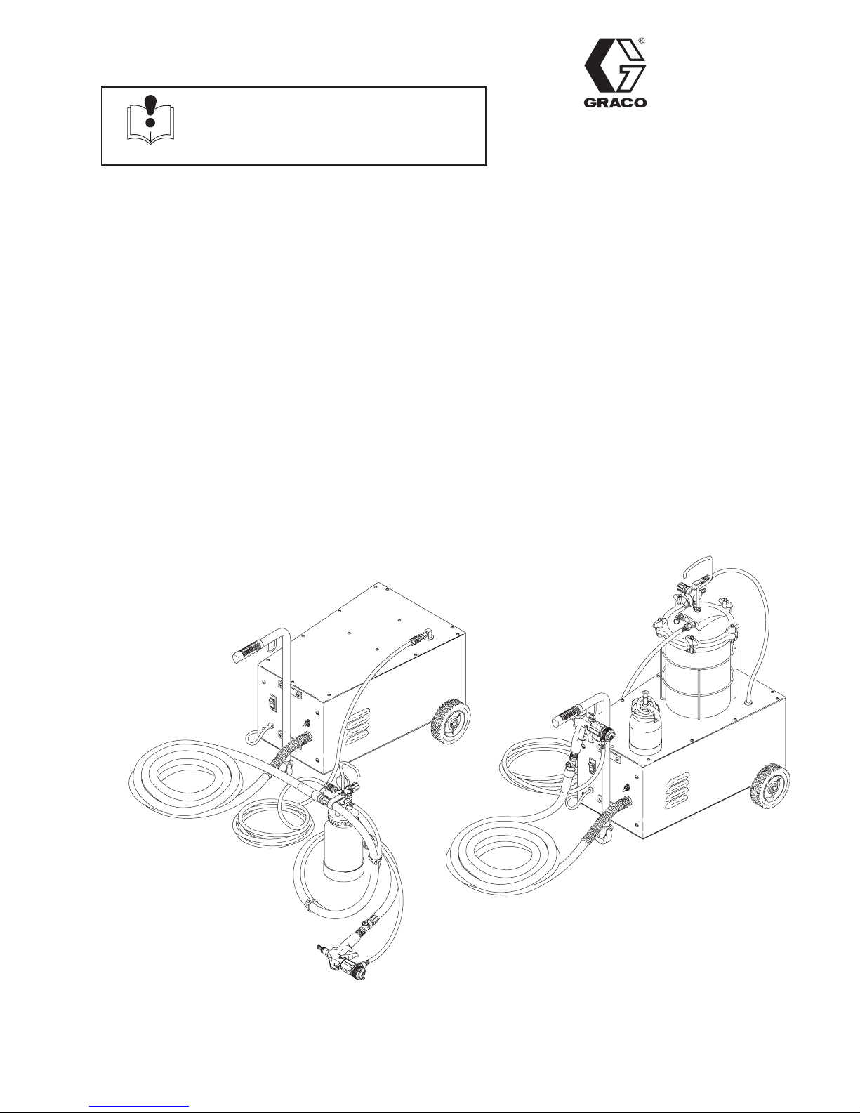
Series 1200 and Series 2000
Turbine Sprayers
110/120V 50/60 Hz
6.0 psi (0.41 bar)
Model M73378
Complete Series 1200 Turbine, with hose and turbine gun
Model M73380
Basic Series 1200 Turbine, without hose or gun
Model M73428
Complete Series 2000 Turbine, with hose and turbine gun
Model M73432
Basic Series 2000 Turbine, without hose or gun
Rev. C
Series 1200 Series 2000
GRACO INC. P.O. BOX 1441 MINNEAPOLIS, MN 55440–1441
03019A
03018A
ECOPYRIGHT 1994, GRACO INC.
Graco Inc. is registered to I.S. EN ISO 9001
Page 2
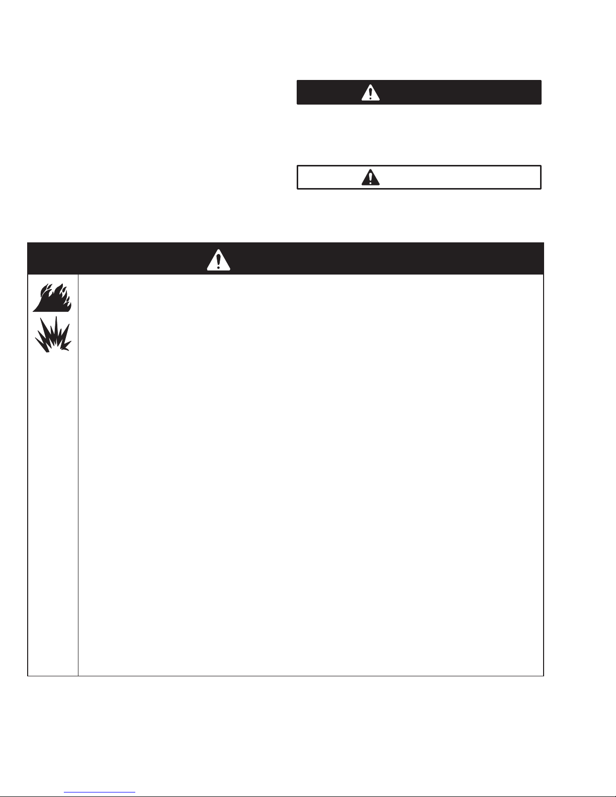
Table of Contents
Symbols
Warnings 2. . . . . . . . . . . . . . . . . . . . . . . . . . . . . . . . . . . . .
General Information 5. . . . . . . . . . . . . . . . . . . . . . . . . . . .
Specifications 5. . . . . . . . . . . . . . . . . . . . . . . . . . . . . . . . . .
Dimensions 5. . . . . . . . . . . . . . . . . . . . . . . . . . . . . . . . . . . .
Setup 6. . . . . . . . . . . . . . . . . . . . . . . . . . . . . . . . . . . . . . . . .
Shutdown 9. . . . . . . . . . . . . . . . . . . . . . . . . . . . . . . . . . . . .
Maintenance 10. . . . . . . . . . . . . . . . . . . . . . . . . . . . . . . . . .
Troubleshooting 11. . . . . . . . . . . . . . . . . . . . . . . . . . . . . . .
Repair 12. . . . . . . . . . . . . . . . . . . . . . . . . . . . . . . . . . . . . . .
Parts
Series 1200 14. . . . . . . . . . . . . . . . . . . . . . . . . . . . . . . . . .
Series 2000 16. . . . . . . . . . . . . . . . . . . . . . . . . . . . . . . . . .
Accessories 18. . . . . . . . . . . . . . . . . . . . . . . . . . . . . . . . . .
Warranty Back Cover. . . . . . . . . . . . . . . . . . . . . . . . . . . . .
WARNING
FIRE AND EXPLOSION HAZARD
Improper grounding, poor ventilation, open flames or sparks can cause a hazardous condition and
result in a fire or explosion and serious injury.
D Ground the equipment. Plug the power supply cord into a properly grounded outlet.
Warning Symbol
WARNING
This symbol alerts you to the possibility of serious
injury or death if you do not follow the instructions.
Caution Symbol
CAUTION
This symbol alerts you to the possibility of damage to
or destruction of equipment if you do not follow the
instructions.
D If there is any static sparking or you feel an electric shock while using this equipment, stop spray-
ing immediately. Do not use the equipment until you identify and correct the problem.
D Provide fresh air ventilation to avoid the buildup of flammable fumes from solvents or the fluid
being sprayed.
D When flammable liquid is sprayed or used for flushing or cleaning the equipment, the turbine must
be placed at least 20 feet (6.1 m) away from areas where hazardous concentrations of flammable
vapors are likely to occur.
D Use additional air hose if necessary to ensure that the turbine is operated in a clean, dry, well
ventilated area.
D Never place the turbine inside a spray booth! Use this equipment outdoors or in extremely well
ventilated areas.
D Keep the spray area free of debris, including solvent, rags, and gasoline.
D Electrically disconnect all equipment in the spray area.
D Extinguish all open flames or pilot lights in the spray area.
D Do not smoke in the spray area.
D Do not turn on or off any light switch in the spray area while operating or if fumes are present.
D Do not operate a gasoline engine in the spray area.
Page 3

INSTRUCTIONS
WARNING
EQUIPMENT MISUSE HAZARD
Equipment misuse can cause the equipment to rupture or malfunction and result in serious injury.
D This equipment is for professional use only.
D Read all instruction manuals, tags, and labels before operating the equipment.
D Use the equipment only for its intended purpose. If you are not sure, call your distributor.
D Do not alter or modify this equipment.
D Check equipment daily. Repair or replace worn or damaged parts immediately.
D Do not exceed the maximum working pressure of the lowest rated system component. The Series
1200 and 2000 turbines have a working pressure of 6 psi (0.41 bar).
D Use fluids and solvents which are compatible with the equipment wetted parts. Refer to the Speci-
fications on page 5 for this information.
D Do not use hoses to pull equipment.
D Route hoses away from traffic areas, sharp edges, moving parts, and hot surfaces. Do not expose
Graco hoses to temperatures above 82_C (180_F) or below –40_C (–40_F).
D Wear hearing protection when operating this equipment.
D Do not lift pressurized equipment.
D Comply with all applicable local, state, and national fire, electrical, and safety regulations.
D Do not point the gun at anyone or at any part of the body.
D Do not put your hand or fingers over the gun fluid nozzle.
D Do not stop or deflect leaks with your hand, body, glove or rag.
D Do not “blow back” fluid; this is not an air spray system.
D Follow the Pressure Relief Procedure on page 9 if the fluid nozzle clogs and before cleaning,
checking or servicing the equipment.
D Tighten all fluid connections before operating the equipment.
D Check the hoses, tubes, and couplings daily. Replace worn or damaged parts immediately.
Page 4

WARNING
TOXIC FLUID HAZARD
Hazardous fluid or toxic fumes can cause serious injury or death if splashed in the eyes or on the skin,
inhaled, or swallowed.
D Know the specific hazards of the fluid you are using.
D Store hazardous fluid in an approved container. Dispose of hazardous fluid according to all local,
state and national guidelines.
D Always wear protective eyewear, gloves, clothing and respirator as recommended by the fluid and
solvent manufacturer.
D Do not use 1,1,1-trichloroethane, methylene chloride, other halogenated hydrocarbon solvents or
fluids containing such solvents in the turbine spray system, which contains aluminum and/or galvanized-coated parts. Such use could result in a serious chemical reaction, with the possibility of
explosion, which could cause death, serious injury, and/or substantial property damage.
Page 5

General Information
PTFE
PTFE
The Series 1200 and 2000 Turbine Spray Guns can
spray most coatings or finishes currently being used
for automotive refinish, industrial, aerospace, marine,
wood, plastic and architectural applications.
The spray gun typically utilizes 6.0 (0.41 bar) inbound
air pressure to produce high quality paint finishes. The
gun produces a cone of air that carries and directs the
paint from the gun to the surface, minimizing overspray
and increasing transfer efficiency. This enables painters to comply with new clean air laws that are designed to reduce VOC (volatile organic compounds)
emissions, eases paint application by requiring fewer
paint passes to obtain coverage, and saves on both
material and clean-up time.
Refer to the turbine gun manual, 308–336, for more
information on the operation and use of the turbine
spray gun.
Unpack the Graco Turbine Sprayer from the shipping
carton and inspect for any possible shipping damage.
If necessary, call the Customer Service toll–free number at 800–328–0211.
The contents of the Series 1200 Turbine Sprayer,
Model M73378, includes:
D 1 Series 1200 Turbine Sprayer, M73304
D 1 Turbine Gun, M73225
D 1 25 ft. hose, M71452
D 1 Female Quick Disconnect, M70402
D 1 2 qt. cup, M70962
D 1 27 ft. braided air hose, M71633
D 10 wire ties, M71179
D 1 Sprayer Instruction Manual, 308–423
D 1 Gun Instruction Manual, 308–336
The contents of the Series 1200 bare sprayer,
Model M73380, includes:
D 1 Series 1200 Turbine Sprayer, M73304
D 1 Sprayer Instruction Manual, 308–423
D 1 Gun Instruction Manual, 308–336
The contents of the Series 2000 Turbine Sprayer,
Model M73428, includes:
D 1 Series 2000 Turbine Sprayer, M73305
D 1 Turbine Gun, M73200
D 1 25 ft. hose, M71452
D 1 2.5 gal pot, M70604
D 1 25 ft material hose, 3/8” id, M71481
D 1 Retainer, M72826
D 1 Sprayer Instruction Manual, 308–423
D 1 Gun Instruction Manual, 308–336
The contents of the Series 2000 bare sprayer,
Model M73432, includes:
D 1 Series 2000 Turbine Sprayer, M73305
D 1 Sprayer Instruction Manual, 308–423
D 1 Gun Instruction Manual, 308–336
Power Requirements 120 VAC, 60 Hz. . . . . . . . . . . . . .
Amps @ 120 volts
Series 1200 1 phase, 14.5 amp minimum. . . . . . . . . . .
Series 2000 1 phase, 14.5 amp minimum. . . . . . . . . . .
Power Cord No. 16 AWG, 3 wire, 10 ft (3 m){. . . . . . . .
CFM unrestricted
Series 1200,Series 2000 115 CFM. . . . . . . . . . . . . . . . .
Turbine Stages 2. . . . . . . . . . . . . . . . . . . . . . . . . . . . . . . . .
Maximum Turbine Hose Length
Series 1200 40 ft (12 m). . . . . . . . . . . . . . . . . . . . . . . . . .
Series 2000 60 ft (18 m). . . . . . . . . . . . . . . . . . . . . . . . . .
Cup or Pot
Series 1200 2 qt pot. . . . . . . . . . . . . . . . . . . . . . . . . . . . .
Series 2000 2.5 gal pot. . . . . . . . . . . . . . . . . . . . . . . . . . .
r is a registered trademark
{ Extension cord must be 3-wire, 12 AWG; 100 ft or shorter.
Turbine Diameter
Series 1200, Series 2000 7.2 in (183 mm). . . . . . . . . . .
Specifications
Wetted Parts
Bare Spray Gun Stainless Steel, r. . . . . . . .
Hard-coated Aluminum,
Spray Gun Cups Aluminum, Polyethylene. . . . . . . .
2 Quart Pressure Pot Aluminum, Polyethylene. . . .
2-1/2 Gallon Remote Pressure Pot Steel, . . . . . . .
black powder coated
Series 1200, Series 2000 Air Compressor
CFM .52. . . . . . . . . . . . . . . . . . . . . . . . . . . . . . . . . . . . . . . .
HP 1/16 HP. . . . . . . . . . . . . . . . . . . . . . . . . . . . . . . . . . . . .
PSI 28 psi (1.7 bar). . . . . . . . . . . . . . . . . . . . . . . . . . . . . . .
Turbine Shipping Weight (w/o pkg, hose, or gun)
Series 1200 69 lb (31 kg). . . . . . . . . . . . . . . . . . . . . . . . .
Series 2000 (2 cartons) 87 lb (40 kg). . . . . . . . . . . . . . .
Dimensions
Page 6
Setup
NOTE: Refer to the turbine gun manual, 308–336, for
information on the operation and setup of the gun.
Connect the Fluid and Air Supply
1. Connect the hose to the gun.
2. Connect the gun air supply hose (A) between the
turbine air outlet (D) and the gun air inlet. See
Fig. 1.
3. If using a spray gun cup (B), connect the cup to
the gun fluid inlet.
4. If using an accessory remote pressure pot (C),
connect the fluid supply hose (G) between the gun
fluid inlet and the remote pressure pot.
Connect the air hose (E) between the pressure pot
air inlet and the compressor air outlet (F).
Air Control Valve
(used to shut off air
without shutting off
turbine)
G
A
NOTES:
D The circled letters in Fig. 1 indicate hose line con-
nections.
D The Series1200 and Series 2000 turbine units
include a compressor for use with a remote pressure pot.
Connect to Electric Supply
1. Plug the sprayer power cord into a grounded
outlet.
2. If an extension cord is used, it must be 3-wire, 12
AWG and 100 ft or less in length.
B
Air Control Valve
(used to shut off
air without
shutting off
turbine)
A
B
Z
EE
Y
G G
Z
CC
X
X
F
Y
Z
Y
2-1/2 Gallon Remote Pressure Pot
Part No. M70604 (see Accessories)
Fig. 1
2 Quart Remote Pressure Pot
Part No. M70962 (see Accessories)
D
X
Series 1200
Turbine shown
02859A
Page 7
Setup
Prepare the Fluid
1. Always strain the fluid before spraying; this
includes color, reducer and hardeners if used.
2. When using a turbine spray system, you need to
use a slower drying reducer or thinner to compensate for the faster drying time caused by the warm
air of the turbine. Do not over reduce.
H
Fig. 2
Accessory Remote Pressure Pot
J
02845
CAUTION
The performance of the turbine sprayer will vary
with the viscosity of the material. Unnecessary hose
length will cause the air pressure to drop.
Paint Reduction – Automotive Type Finishes
Reduce and catalyze all paint to manufacturer’s specifications. To compensate for the faster drying time of
turbine systems, use a reducer one-step slower than
what is used for conventional air spray.
Paint Reduction – Industrial or Domestic Coatings
Reduce and catalyze all paint to manufacturer’s specifications. If no reductions are given, first thoroughly
mix the fluid to be sprayed. Then gradually mix in the
proper reducer, testing the fluid until you have the
correct spraying consistency.
To test the consistency: Remove the stir stick from the
thinned paint. When the paint stream running off the
stir stick breaks into droplets, the first few drops should
be about one second apart.
WARNING
The remote pressure pots remain pressurized until
pressure is manually relieved. To reduce the risk of
serious injury from pressurized fluid or accidental
spray from the gun, always relieve pressure in the
pressure pot before loosening or removing the
cover.
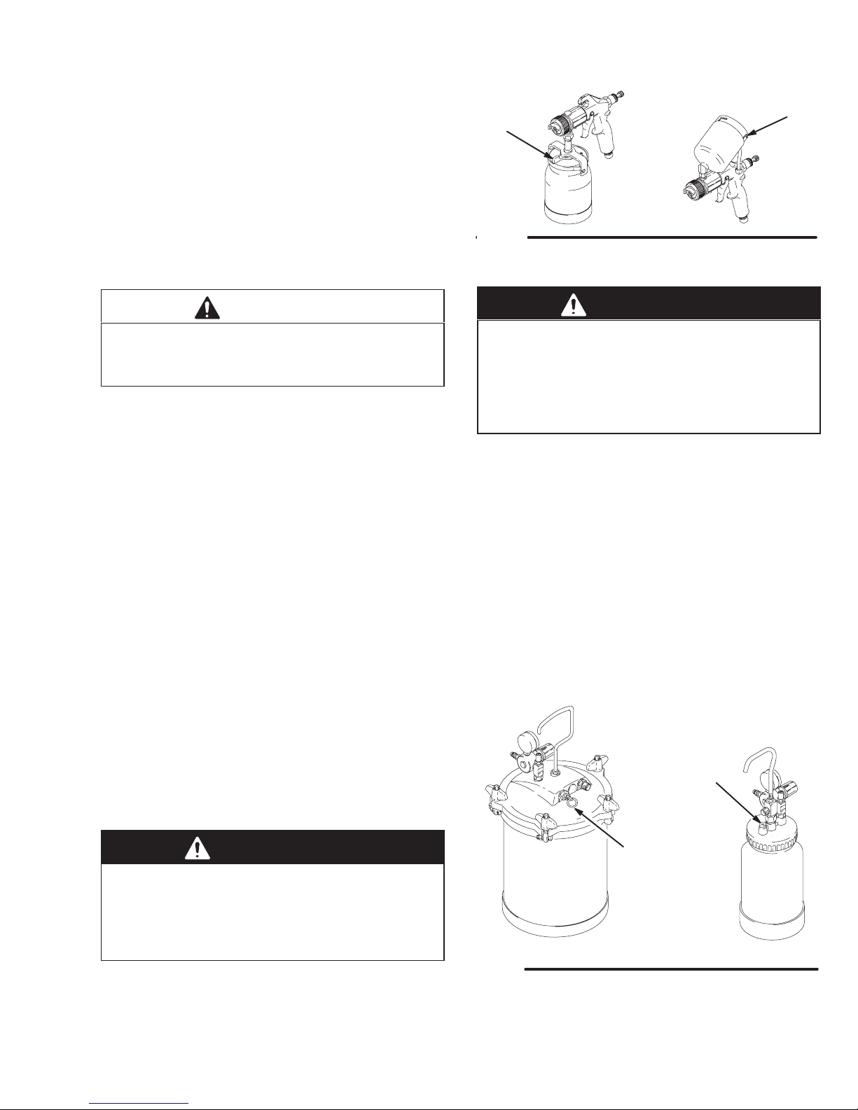
1. Relieve the remote pressure pot pressure by
following these steps:
a. Turn off the air supply to the pressure pot.
b. 2 1/2 Gallon Remote Pot: Pull the pressure
relief valve ring (205) until pressure is completely relieved.
2 Quart Remote Pot: Turn out the pressure
relief knob (113) about one turn. Wait until
pressure is completely relieved before removing the cover. Close the knob before using the
system again.
See Fig. 3.
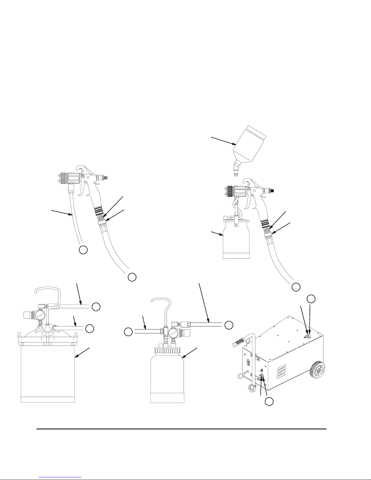
Fill the Cup or Remote Pressure Pot
Spray Gun Cup
WARNING
The spray gun cup is pressurized by the gun’s air
supply. To reduce the risk of serious injury from
pressurized fluid or accidental spray from the gun,
always turn off the air supply to the gun before
removing the spray gun cup.
Only fill the cup 3/4 full to help keep the air pressure
tube clean, then install the cover. The under-cup cover
has a latch (H) to secure it to the cup. The over-cup
has a ring with notches (J) that secures the cup hood
into place when locked in place on the cup.
113
205
2 1/2 gallon
Fig. 3
2. Remove the pressure pot cover and fill the pressure pot. Secure the cover.
NOTE: 2 quart remote pressure pot only: lightly coat
the cover threads with petroleum jelly.
02860A
2 quart
02882A
Page 8

Setup
CAUTION
If the 2 quart remote pressure pot is accidentally
tipped over or held at too great of an angle, fluid may
leak into the air regulator. Take precautions to avoid
this. If fluid does get into the regulator, clean it immediately.
CAUTION
1. Turn the turbine on a few minutes before you start
spraying to allow for warm-up time. Turn the
turbine off when it is not in use; it does not shut off
automatically.
2. Be sure the turbine filter is clean before operating.
See page 10 to check and clean the filter.
Do not tighten the pressure pot cover more than
hand-tight. Excessive tightening may damage the
cover gasket.
Prepare the Surface to be Sprayed
To achieve proper adhesion, make sure the surface to
be sprayed is completely clean.
Operating the Turbine
WARNING
Sparking can be expected in the normal operation
of the turbine motor. Sparks could ignite fumes
from flammable liquid, dust particles and other
flammable substances in the spray area, and
cause serious injury and property damage. Be sure
to follow the precautions below:
D When flammable liquid is sprayed or used for
flushing or cleaning equipment, the turbine must
be placed at least 20 feet (6.1 m) away from
areas where hazardous concentrations of
flammable vapors are likely to occur.
D Use additional air hose if necessary to ensure
that the turbine is operated in a clean, dry, well
ventilated area.
Series 1200 and Series 2000 Cold Weather
Operation
Turbine Spray Models Series 1200 and 2000 have a
diaphragm compressor. When these compressors are
new, the diaphragm will become stiff in cold weather. If
cold enough, the stiff diaphragm will not allow the
compressor to start (the unit will hum). If this occurs,
follow these steps:
1. Turn the turbine and compressor off.
2. Unplug the turbine from the power source.
3. Loosen the four main filter screws and remove the
filter; replace the main filter and pre-filter if they
are dirty.
4. Hand spin the cooling fan on the compressor for a
few revolutions.
D Never place the turbine inside a spray booth!
Use this equipment outdoors or in extremely
well ventilated areas.
D Avoid all ignition sources such as static electric-
ity from plastic drop cloths, open flames such as
pilot lights, hot objects such as cigarettes, arcs
from connecting or disconnecting power cords
or turning light switches on and off. Extinguish
or remove all sources of ignition.
5. Reassemble the turbine.
6. Plug in the turbine and turn the compressor on.
The compressor should start.
NOTE: To adjust the spray gun pattern, see the
turbine gun manual 308–336.
Page 9

Shutdown
Pressure Relief Procedure
WARNING
PRESSURIZED EQUIPMENT HAZARD
The equipment stays pressurized until pressure is
manually relieved. To reduce the risk of a serious
injury from pressurized fluid, accidental spray from
the gun, or splashing fluid, follow the Pressure
Relief Procedure whenever you:
D are instructed to relieve the pressure,
D stop spraying,
D check or service any of the system equipment,
D or install or clean the spray nozzle.
1. When spraying is finished, turn off the air supply to
the gun.
2. Turn off the turbine sprayer.
b. 2 1/2 Gallon Remote Pot: Pull the pressure
relief valve ring (206c) until pressure is completely relieved.
2 Quart Remote Pot: Turn out the pressure
relief knob (113) about one turn. Wait until
pressure is completely relieved before removing the cover. Close the knob before using the
system again.
See Fig. 4.
113
206c
2 1/2 gallon
2 quart
WARNING
The turbine hose outlet may be hot. Carefully
check the hose end before removing the hose.
3. If using a remote pressure pot, relieve its pressure
by following these steps:
a. Turn off the air supply to the pressure pot.
Fig. 4
02882A02860A
NOTE: Elevate the spray gun and pull the trigger. This
will allow the fluid in the fluid hose to drain back into
the remote pressure pot.
4. If using a spray gun cup, unlatch the cup cover
and loosen or remove the cup from the cover to
relieve the cup pressure.
5. Clean the spray gun and cup as instructed in
Turbine Spray Gun Manual 308–336.
Page 10

Maintenance
Daily
Check the main turbine filter daily for cleanliness.
The turbine systems are lifetime lubricated. The only
maintenance required is filter cleaning and replacement.
The turbine main filter and pre-filter must be clean at
all times to provide sufficient air flow to cool the motor
and atomize the fluid. Check the filters weekly, minimum. Replace the pre-filter as required.
NOTE: To check the filter, turn on the turbine and
place a piece of paper against the air intake filter. If the
air intake holds the paper in place, the filter is okay.
To clean the main filter:
1. Turn off and unplug the turbine.
2. Loosen the four main filter screws. See Fig. 5.
CAUTION
Do not operate the turbine sprayer without the filter
installed.
Main
filter screws
3. Remove the main filter and clean it by following
one of the following three methods:
D Tap the filter gently on a flat surface, dirty side
down.
D Direct compressed air (100 psi [7 bar] maxi-
mum) through the filter panel in the opposite
direction of the arrows on the side of the filter.
D Soak the filter for 15 minutes in water and a
mild detergent. Rinse the filter until it is clean.
Air dry the filter; do not use compressed air.
WARNING
To avoid damage to the turbine and possible electric shock, never install a damp filter in the turbine.
Fig. 5
03079
Weekly
1. Check the hose for cracks, leaks, and holes.
Replace, if necessary.
Annually or 600 Hours (whichever comes
first)
1. Replace the motor brushes 600 hours after turbine
sprayer operation. If the brushes are not replaced,
motor failure will occur.
NOTE: It is recommended that an authorized service
center perform the motor brush replacement. See the
procedure on page 13.
Page 11

Troubleshooting
PROBLEM CAUSE SOLUTION
Remote Container Pressurization
Series 1200 and Series 2000
Compressor fails to start
No fluid delivery. Check for leaks at the container gasket,
2 quart lid, and 2 1/2 gal pot wing nuts.
Check for air flow from male quick–dis-
connect at compressor outlet (approx.
1/4 CFM).
Turn pressure regulator clockwise. Look
for pressure on gauge. (If no pressure on
gauge, check air line and fittings).
Check hole in tank lid under regulator or
needle valve 2 Qt lid. Clean if necessary.
Check for obstructions.
Check if fluid pickup tube is unplugged.
Tighten.
Blow out and clear material hose.
Check container for material.
Cold weather operation. See Cold Weather Operation instruc-
tions, page 8.
Turbine fails to start Power supply. Cycle red rocker switch.
Poor atomization Dirty filter. Clean filter.
Extension cord too long. Replace with shorter extension cord (do
not exceed 100 ft). Extension cord must
be 3-wire, 12 AWG.
Hose length too long. Replace with shorter hose. See Acces-
sories for shorter hose and P/N.
Red Rocker Circuit Breaker
Switch Trips
Check filter. Clean filter and replace as necessary.
Excessive high ambient temperature. Move turbine to cooler area.
Excessive brush wear. Remove turbine wrapper and:
. Check for free motor rotation,
. Check brush wear,
. Replace motor brushes if necessary.
Excessive current draw. Return to authorized service center.
Page 12

Repair
WARNING
Turn off turbine and unplug power for the following
procedures.
Turbine Switch Replacement (Red Rocker Circuit
Breaker)
1. To remove the turbine switch, wedge a large flat
blade screwdriver between the top of the switch
and the turbine face plate.
2. Push down firmly on the switch. Pry the switch out
far enough so the two top switch locking tabs are
visible.
Top Cover
Screws
Front Screws
3. While maintaining outward pressure on the switch,
push down on the two locking tabs with a small flat
blade screwdriver until they release. The switch
will pop out.
4. Disconnect the two wires and remove the switch.
5. Reinstall by connecting the wires to the new
switch. Snap the switch into place.
Locking Tabs
Fig. 6
Turbine Wrapper Removal
1. Remove the four main filter stop screws and
remove the main filter. (Clean or replace as necessary. See Maintenance.)
03728
Fig. 7
Power Cord Replacement
Remove the cabinet wrapper by following the steps in
the Wrapper Removal procedure.
6. Pry up and slide the top half of the motor mount
(44) to the rear of the cabinet. The power cord
can now be replaced.
Series 1200, Series 2000 Compressor Replacement
1. Remove the four main filter stop screws and
remove the filter. (Clean or replace as necessary.
See Maintenance.)
2. Remove the air hose from the barbed fitting on the
check valve.
3. Remove the three compressor hold–down screws
on the bottom of the unit.
4. Remove the ground screw, clip the lead wires, and
remove the compressor.
5. Remove the relief valve and install it on the new
compressor. (Do not use tape or sealant)
Series 1200 shown
03074
2. Remove the nine top cover screws. Do not remove the three paint tank retainer screws.
3. Gently pry up on the top cover and remove. (The
wrapper is sealed with caulk.)
4. Remove the top two 1/4 x 20 pan head screws
from the cabinet front. Do not remove the handle
screws.
5. Remove the three screws (40) that the top half of
the motor mount to the bottom half of the motor
mount.
6. Rewire and install the compressor. Use removable
Loc–Tite on the compressor screws. Do not
overtighten the rubber bumpers.
7. Re–install the hose and filter.
Series 1200, Series 2000 Compressor Toggle
Switch Replacement
Remove the cabinet wrapper by following the steps in
the Wrapper Removal procedure.
1. Slide the motor mount to the rear of the cabinet.
The toggle switch can now be replaced.
Page 13

Repair
Motor/Turbine Replacement
Remove the cabinet wrapper by following the steps in
the Turbine Wrapper Removal procedure. See Fig. 7
for Series 1200 and Series 2000.
1. The motor can now be replaced. Use the motor
assembly kit M73526, which contains: rubber
bottom spacer (46), foam fan seal (90), ground
ring (11), switch connector (12), and wire butt
connector (13).
2. Remove the nut on the ground stud and switch
wire. Clip the neutral lead about 2 in. from the
3-wire crimp connector.
3. Remove the motor mount and replace the motor.
Do not overtighten the three rubber stop bushings.
Snug up only until the motor is held firmly in place.
Apply removable LocTiter to the three mounting bolts before installing.
Compressor
Green
Green
Black
White
Fig. 8
Motor Brush Replacement
NOTE: It is recommended that this procedure be
performed by an authorized service center.
White
Black
Series 1200 and Series 2000
Motor
Whit
e
Rocker
Switch
Black
Green
Black
Black
Black
Power
Cord
Toggle
Switch
03734A
4. Hook up the switch wire, neutral butt connector,
and Loc–tite the ground screw nut.
5. Gently slide the top half to the motor mount (44) to
the front of the cabinet. Make sure the side foam
doesn’t catch on the mount.
6. Re–install the top two 1/4 x 20 front screws and
the three sheet metal screws (40).
7. Install the foam fan seal around fan intake.
8. Caulk the top flange of the cabinet with a fine bead
of acrylic latex caulk.
9. Replace the top and main filter.
1. Follow the steps for removing the motor in the
Motor Replacement procedure.
2. Remove the brushes by prying up the metal clip
retainers on the top half of the turbine. Check the
commutator for excessive wear. If the commutator
has wear, replace the motor. See Motor Replacement procedure.
3. Use the Motor Brush Kit, M73522, and reassemble
the new motor brushes using the reverse order
Keep the lead wires from all rotating parts and
from the motor frame.
CAUTION
Do not run the motor with the air inlet or outlet
sealed off.
4. Reinstall the motor in reverse order.
5. After running the motor for 30–45 minutes at
full-rated voltage, the motor will return to full performance.
Page 14

Parts for Series 1200
66
3
63
90
44
13
11
12
18
19
46
45
43
4
9
1
8
40
65
64
64
59
62
51
50
47
35
34
33
31
91
83
15
37
4
14
9
10
24
21
26
93
94
93
95
5
93
22
16
25
62
61
29
32
30
6,7
27
28
03077A
Page 15

Parts for Series 1200
Ref
No. Part No. Description Qty
1 M70739 HANDLE, with grip 1
3 M71603 DECAL, warning (not shown) 1
4 M70603 SWITCH, toggle 1
5 M70811 SWITCH, plate 1
6 M73030 DECAL, RH (not shown) 1
7 M73031 DECAL, LH (not shown) 1
8 M70657 SWITCH, rocker 1
9 M70789 SCREW, 1/4x20x3/4 8
10 M71686 CORD, power 1
11 102799 CABLE, terminal 2
12 107260 SWITCH, connector 2
13 M71190 CONNECTOR, blue butt 1
14 111348 GROMMET, cord 1
15 M70740 CASTER 1
16 M73047 WRAPPER 1
18 M71246 O-RING 1
19 M71262 FITTING, air outlet 1
20 728677 LABEL (not shown) 1
21 M71180 WIRE, green 1
22 M70744 SCREW, black oxide 8–32x1/2 27
24 M73300 BASE, bottom 1
25 M71137 COMPRESSOR, 110V 1
26 M70763 BUMPER 3
27 M70747 WHEEL, 6 in 2
28 M70748 CAP, hub 2
29 M70749 PIN, cotter 2
31 M70757 FOAM, filter stop 3
32 M70746 AXLE 1
Ref
No. Part No. Description Qty
33 M70609 FILTER, main 1
34 M71188 VELCRO, strips .5
35 M70607 FILTER, pre 1
37 M70773 WASHER, 1/4 6
40 113400 SCREW 3
43 M73014 MOUNT, motor, bottom 1
44 M73013 MOUNT, motor, top 1
45 M70776 NUT, keps 3
46 M73039 PAD, rubber, turbine 1
47 M73020 SPACER, 2.6 3
50 M70764 RING, 0–ring 3
51 M70770 BOLT, 1/4–20x3.5 3
52 M73526 *MOTOR, Kit 1
61 M71192 HOSE, 8” 1
62 M70809 FITTING, barbed hose 1
63 M73049 LID 1
64 M71136 WASHER 2
65 114047 FITTING, QD 1
66 178945 NUT, hex 1
83 M70741 SOCKET 1
90 M73037 GASKET, fan seal 1
91 M71452 HOSE, 25 ft 1
93 M70721 O-RING, valve 3
94 M70397 VALVE, air 1
95 M70402 DISCONNECT, quick 1
* Motor Brush Kit M73522 is also available. Purchase separately.
Compressor
Green
Black
White
Fig. 9
Green
White
Black
Motor
White
Series 1200
Green
Black
Black
Rocker
Switch
Black
Black
Power
Cord
Toggle
Switch
03734A
Page 16

Parts for Series 2000
91
90
13
11
12
18
19
46
45
43
93
93
94
93
95
22
3
75
96
73
74
63
90
40
44
51
50
47
35
4
9
8
1
4
58
5
25
59
60
30
83
15
14
21
9
26
10
24
22
16
37
29
32
34
33
31
6,7
27
28
03078A
Page 17

Parts for Series 2000
Ref
No. Part No. Description Qty
1 M70739 HANDLE, with grip 1
3 M71603 DECAL, warning (not shown) 1
4 M70603 SWITCH, toggle 1
5 M70811 SWITCH, plate 1
6 M73032 DECAL, RH (not shown) 1
7 M73033 DECAL, LH (not shown) 1
8 M70657 SWITCH, rocker 1
9 M70789 SCREW, 1/4x20x3/4 8
10 M71686 CORD, power 1
11 102799 CABLE, terminal 2
12 107260 SWITCH, connector 2
13 M71190 CONNECTOR, blue butt 1
14 111348 GROMMET, cord 1
15 M70740 CASTER 1
16 M73047 WRAPPER 1
18 M71246 O-RING 1
19 M71262 FITTING, air outlet 1
21 M71180 WIRE, green 1
22 M70744 SCREW, black oxide 8–32x1/2 31
24 M73300 BASE, bottom 1
25 M71137 COMPRESSOR, 110V 1
26 M70763 BUMPER 3
27 M70747 WHEEL, 6 in 2
28 M70748 CAP, hub 2
29 M70749 PIN, cotter 2
31 M70757 FOAM, filter, stop 3
32 M70746 AXLE 1
33 M70609 FILTER, main 1
34 M71188 VELCRO, strips .5
Ref
No. Part No. Description Qty
35 M70607 FILTER, pre 1
37 M70773 WASHER, 1/4 6
40 113400 SCREW 3
43 M73014 MOUNT, motor, bottom 1
44 M73013 MOUNT, motor, top 1
45 M70776 NUT, keps 3
46 M73039 PAD, rubber, turbine 1
47 M73020 SPACER, 2.6 3
50 M70764 O-RING 3
51 M70770 BOLT, 1/4–20x3.5 3
52 M73526 *MOTOR, Kit 1
58 M70955 ELBOW, 1/4 pipe 1
59 M70736 VALVE, relief 1
60 M70804 FITTING, barbed 1
63 M73049 LID 1
73 M70803 HOSE, 3 ft 1
74 M70806 GROMMET, air line 1
75 M70911 COUPLER, 1–4 hose barb 1
83 M70741 SOCKET 1
90 M73037 GASKET, fan seal 1
91 M71452 HOSE, 25 ft 1
93 M70721 O-RING, valve 3
94 M71681 VALVE, air 1
95 M70402 DISCONNECT, quick 1
96 M72826 RETAINER, paint tank 1
* Motor Brush Kit M73522 is also available. Purchase separately.
Compressor
Green
Black
White
Fig. 10
Green
White
Black
Motor
White
Series 2000
Green
Black
Black
Rocker
Switch
Black
Black
Power
Cord
Toggle
Switch
03734A
Page 18

Accessories
2-1/2 Gallon Pressure Pot M70604
50 psi (3.5 bar) Maximum Inlet Air Pressure
2-1/2 gallon (9.5 liter) capacity, galvanized steel tank.
Includes an air pressure regulator and gauge and a
pressure relief valve.
Ref.
No. Part No. Description Qty.
201 104655 PRESSURE GAUGE 1
202 151519 HEX NIPPLE, 1/4 in. x 1/8 in. 1
203 M70687 COUPLING 1
204 M70676 O-RING 1
205 M70686 PRESSURE RELIEF VALVE 1
206 M70685 FLUID TUBE 1
207 M70616 GASKET, standard; EPDM 1
M70617 GASKET, solvent resistant; Thiokol
(optional–must order separately) 1
208 M70678 WING NUT 5
209 M70677 WASHER 5
210 M70680 EYE BOLT 5
211 M70684 BAND 5
212 M70683 POT, 2-1/2 gallon (9.5 liter),
black powder coat 1
213 M70681 SCREW, band 5
214 M70682 NUT, band 5
215 M70688 COVER 1
216 169969 QUICK DISCONNECT, male 1
217 104815 PRESSURE REGULATOR 1
201
216
217
202
215
204
205
206
211
208
209
203
207
214
210
213
212
Retainer for Paint Tank M72826
For paint tank.
Plastic Liners M70695
For paint tank, quantity 5.
02861A
Page 19

Accessories
2 Quart Pressure Pot M70962
50 psi (3.5 bar) Maximum Inlet Air Pressure
2 quart (1.94 liter) capacity, aluminum cup.
Includes an air pressure regulator and gauge, pressure
relief valve, and rigid hook handle.
WARNING
Do not use 1,1,1-trichloroethane, methylene chloride, other halogenated hydrocarbon solvents or
fluids containing such solvents in the turbine spray
system, which contains aluminum and/or galvanized-coated parts. Such use could result in a
chemical reaction, with the possibility of explosion,
which could cause death, serious injury, and/or
substantial property damage.
Ref.
No. Part No. Description Qty.
101 104655 PRESSURE GAUGE 1
102 M70727 SAFETY VALVE 1
103 104815 PRESSURE REGULATOR 1
104 M70731 SPRING 1
105 189557 RESTRICTOR 1
106 M70733 BRACKET 1
107 M70734 VALVE 1
108 M70735 SCREW 1
109 M70730 POT, 2 quart (1.94 liter), aluminum 1
110 M70729 FLUID TUBE 1
111 M70728 COVER 1
112 M71425 GASKET, polyethylene (5 pack) 1
113 M70726 PRESSURE RELIEF KNOB 1
114 M70725 FITTING 1
115 M70724 FLUID OUTLET 1
116 M70723 NUT 1
117 M70722 HANDLE 1
118 169969 PLUG, male, quick disconnect 1
119 110440 TEE 1
120 M71491 HOSE, fluid; 5 ft. (1.5 m) long;
1/4 in. (6.35 mm) ID 1
121 M71470 HOSE, air; 4.5 ft. (1.4 m) long 1
122 M70854 HOSE CLAMP 1
123 M70402 QUICK DISCONNECT, female 1
124 M71681 AIR CONTROL VALVE 1
125 M70721 O-RING, air valve 1
126 M70399 QUICK DISCONNECT, male 1
127 M70721 O–RING, hose 1
128 M72842 FITTING, air pressure stem 1
NOTE: See selection charts in the gun turbine manual,
308–336, to order fluid sets.
NOTE: Handle (117) is shipped inside pot (109).
117
122
126
127
121
116
115
118
101
103
102
105
119
128
113
114
120
111
107
104
106
125
110
112
108
124
123
109
02951
Page 20

Accessories
Lubricant 111–265
One 4 oz (113 gram) tube sanitary (non-silicone)
lubricant for fluid seals and wear areas.
#4 Ford Viscosity Cup M70702
To measure viscosity of fluid.
1 Quart Cup Lid M70610
Fits on cup M71667 for air tight storage of fluid.
1 Quart Cup M71667
1 quart under-cup.
1 Quart Under-Cup Assembly M71660
Complete 1 quart under-cup assembly.
1 Quart Cup Gaskets M70425
5 pack of polyethylene gaskets for use with 1 quart
under-cup.
Cup Check Valve M71007
To help prevent the cup from depressurizing after the
air is shut off.
Fluid Strainer M70464
Install on the end of the cup or pressure pot fluid tube
to strain the fluid and help eliminate surface blemishes
and plugged tips. 100 mesh screen.
Air Control Valve M71681
Compressor Unloader Valve Kit M70691
Series 1200 and 2000 Motor Assembly Kit M73526
Series 1200 to Series 2000 Conversion Kit M71513
Series 1200 and Series 2000 Compressor Kit
M70692
Series 1200, Series 2000 Motor Brush Kit M73522
Includes:
45 Degree Elbow M70593
Prefilter 12–Pak M70608
5 Pak Tank Liner M70695
2 Qt. Gasket, 5 Pak M71425
Main Filter with Velcro Strips M71558
2 1/2 gal Paint Tank M70604
27 ft x 1/4 in. ID Replacement Air Hose for 2 Quart
Remote Cup M71633
Clear Air Hose Extension for 2 qt cup M70665
20 ft compressor air hose, 1/4 in., male quick disconnect on one end, female quick disconnect on the other
end.
Blow Gun M70703
For dusting and drying. With quick disconnect.
Contractor User Kit M70704
Used for fine finish materials and heavier bodied
materials (latex).
Includes:
Part No. Description
M70562 1.0 mm Fluid Set
M70582 2.0 mm Fluid Set
M70425 1 Quart Under-cup Gaskets (5-pack)
M70464 Fluid Strainer
M70395 Upper Air Pressure Hose
– Parts Box with Compartments
Automotive User Kit M70705
For use with automotive finishes.
Includes:
Part No. Description
M70559 1.0/0.05 mm Fluid Set
M70647 1.2/0.7 mm Fluid Set
M70425 1 Quart Under-cup Gaskets (5-pack)
M70464 Fluid Strainer
M70395 Upper Air Pressure Hose
– Parts Box with Compartments
3/8 in. id Paint Fluid Hose
25 ft M71481
15 ft M71482
30 ft M71484
50 ft M71485
40 ft M71486
Material Hose Connector M70693
For use with 3/8 in. paint fluid hose.
3/4 in. ID Turbine Air Hose with Spring
PVC, Maximum Working Pressure: 100 psi (6.9 bar)
Part No. Length
M71452 25 ft
M71453 30 ft
M71454 40 ft
M71455 50 ft
3/4 in. ID Turbine Air Hose Extension without
Spring
PVC, Maximum Working Pressure: 100 psi (6.9 bar)
Part No. Length
M71460 10 ft
M71461 15 ft
M71462 20 ft
M71463 25 ft
M71464 30 ft
Page 21

Notes
Page 22

The Graco Warranty and Disclaimers
Graco warrants all equipment referenced in this document which is manufactured by Graco and bearing its name to be free from
defects in material and workmanship on the date of sale by an authorized Graco distributor to the original purchaser for use. With the
exception of any special, extended, or limited warranty published by Graco, Graco will, for a period of twelve months from the date of
sale, repair or replace any part of the equipment determined by Graco to be defective. This warranty applies only when the equipment
is installed, operated and maintained in accordance with Graco’s written recommendations.
This warranty does not cover, and Graco shall not be liable for general wear and tear, or any malfunction, damage or wear caused by
faulty installation, misapplication, abrasion, corrosion, inadequate or improper maintenance, negligence, accident, tampering, or substitution of non–Graco component parts. Nor shall Graco be liable for malfunction, damage or wear caused by the incompatibility of
Graco equipment with structures, accessories, equipment or materials not supplied by Graco, or the improper design, manufacture,
installation, operation or maintenance of structures, accessories, equipment or materials not supplied by Graco.
This warranty is conditioned upon the prepaid return of the equipment claimed to be defective to an authorized Graco distributor for
verification of the claimed defect. If the claimed defect is verified, Graco will repair or replace free of charge any defective parts. The
equipment will be returned to the original purchaser transportation prepaid. If inspection of the equipment does not disclose any defect
in material or workmanship, repairs will be made at a reasonable charge, which charges may include the costs of parts, labor, and
transportation.
THIS WARRANTY IS EXCLUSIVE, AND IS IN LIEU OF ANY OTHER WARRANTIES, EXPRESS OR IMPLIED, INCLUDING BUT
NOT LIMITED TO WARRANTY OF MERCHANTABILITY OR WARRANTY OF FITNESS FOR A PARTICULAR PURPOSE.
Graco’s sole obligation and buyer’s sole remedy for any breach of warranty shall be as set forth above. The buyer agrees that no other
remedy (including, but not limited to, incidental or consequential damages for lost profits, lost sales, injury to person or property, or any
other incidental or consequential loss) shall be available. Any action for breach of warranty must be brought within two (2) years of the
date of sale.
GRACO MAKES NO WARRANTY, AND DISCLAIMS ALL IMPLIED WARRANTIES OF MERCHANTABILITY AND FITNESS FOR
A PARTICULAR PURPOSE, IN CONNECTION WITH ACCESSORIES, EQUIPMENT, MATERIALS OR COMPONENTS SOLD
BUT NOT MANUFACTURED BY GRACO. These items sold, but not manufactured by Graco (such as electric motors, switches,
hose, etc.), are subject to the warranty, if any, of their manufacturer. Graco will provide purchaser with reasonable assistance in making any claim for breach of these warranties.
In no event will Graco be liable for indirect, incidental, special or consequential damages resulting from Graco supplying equipment
hereunder, or the furnishing, performance, or use of any products or other goods sold hereto, whether due to a breach of contract,
breach of warranty, the negligence of Graco, or otherwise.
FOR GRACO CANADA CUSTOMERS
The parties acknowledge that they have required that the present document, as well as all documents, notices and legal proceedings
entered into, given or instituted pursuant hereto or relating directly or indirectly hereto, be drawn up in English. Les parties reconnaissent avoir convenu que la rédaction du présente document sera en Anglais, ainsi que tous documents, avis et procédures judiciaires
exécutés, donnés ou intentés à la suite de ou en rapport, directement ou indirectement, avec les procedures concernées.
Graco Phone
Number
TO PLACE AN ORDER, contact your Graco distributor, or call this number to identify the distributor
closest to you: 1–800–690–2894 Toll Free
This manual was changed, partially, per ECO F5372.
The parts list was changed for the Series 1200, but not
the parts drawing. The Series 2000 was not changed
at all – neither parts list nor parts drawing – because it
reflects the older Series 2000. The Series 1200 parts
list was changed because it reflects both of the newer
Series 1200 and 2000.
Manual Change
Summary
All written and visual data contained in this document reflects the latest product information available at the time of publication.
Graco reserves the right to make changes at any time without notice.
Foreign Offices: Belgium, Korea, Hong Kong, Japan
GRACO INC. P.O. BOX 1441 MINNEAPOLIS, MN 55440–1441
PRINTED IN USA 308423 January 1994, Revised 02/2000
Sales Offices: Minneapolis, Detroit
www.graco.com
 Loading...