

Page 1
INSTRUCTIONS-PARTS
LIST
308–422
This
manual contains important
warnings and information.
READ AND KEEP FOR REFERENCE.
INSTRUCTIONS
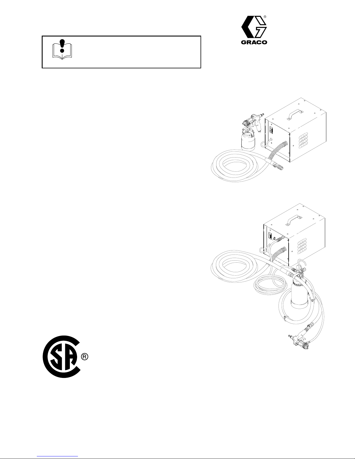
Series
T
urbine Sprayers
120 VAC 50/60 Hz: Series 700 and 900
120 VAC 60 Hz: Series 800
Maximum Working Pressure:
Series 700 and 800: 5 psi (0.34 bar)
Series 900: 6 psi (0.41 bar)
Model
Complete Series 700 T
M73109, Series A
700, 800, and 900
urbine, with hose and turbine gun
Model M73111, Series A
Basic Series 700 T
urbine, without hose or gun
Series
Supersedes A
700 and 900
Rev. B
03015
Model M73154, Series A
Complete Series 800 T
urbine,
with remote 2 qt cup, hose, and turbine gun
Model M73157, Series A
Basic Series 800 T
urbine, without hose or gun
Model M73331, Series A
Complete Series 900 T
urbine, with hose and turbine gun
Model M73333, Series A
Basic Series 900 T
urbine, without hose or gun
Series 800
03016A
GRACO INC. P.O. BOX 1441
MINNEAPOLIS, MN
COPYRIGHT
Graco
Inc. is registered to I.S. EN ISO 9001
1994, GRACO INC.
55440–1441
Page 2
Table
Warnings 2.
General
Specifications 6
Dimensions 6
Setup 7
Shutdown 11
Maintenance 12
Troubleshooting 13
Repair 14
Parts 18
Accessories 24
Warranty Back
. . . . . . . . . . . . . . . . . . . . . . . . . . . . . . . . . . . . .
Information5. . . . . . . . . . . . . . . . . . . . . . . . . . . .
. . . . . . . . . . . . . . . . . . . . . . . . . . . . . . . . . . . . . . . . .
. . . . . . . . . . . . . . . . . . . . . . . . . . . . . . . . . . . .
. . . . . . . . . . . . . . . . . . . . . . . . . . . . . . . . . . . . . . .
. . . . . . . . . . . . . . . . . . . . . . . . . . . . . . . . . . . . . . . .
.
. . . . . . . . . . . . . . . . . . . . . . . . . . . .
of Contents
. . . . . . . . . . . . . . . . . . . . . . . . . . . . . . . . . .
. . . . . . . . . . . . . . . . . . . . . . . . . . . . . . . . . . . .
. . . . . . . . . . . . . . . . . . . . . . . . . . . . . . . . . .
. . . . . . . . . . . . . . . . . . . . . . . . . . . . . . .
. . . . . . . . . . . . . . . . . . . . . . . . . . . . . . . . . .
Cover
WARNING
FIRE AND EXPLOSION HAZARD
Symbols
Warning Symbol
WARNING
This
symbol alerts you to the possibility of serious
injury or death if you do not follow the instructions.
Caution Symbol
CAUTION
This
symbol alerts you to the possibility of damage to
or destruction of equipment if you do not follow the
instructions.
Improper
result in a fire or explosion and serious injury
D
D
D
D
D
D
D
D
D
grounding, poor ventilation, open flames or sparks can cause a hazardous condition and
.
Ground the equipment and the object being sprayed. Refer to
If there is any static sparking or you feel an electric shock while using this equipment,
ing immediately. Do not use the equipment until you identify and correct the problem.
Provide fresh air ventilation to avoid the buildup of flammable fumes from solvents or the fluid
being sprayed.
When flammable liquid is sprayed or used for flushing or cleaning the equipment, the turbine must
be placed at least 20 feet (6.1 m) away from areas where hazardous concentrations of flammable
vapors are likely to occur
Use additional air hose if necessary to ensure that the turbine is operated in a clean, dry
ventilated area.
Never place the turbine inside a spray booth! Use this equipment outdoors or in extremely well
ventilated areas.
Keep the spray area free of debris, including solvent, rags, and gasoline.
Electrically disconnect all equipment in the spray area.
Extinguish all open flames or pilot lights in the spray area.
.
Grounding
on page 8.
stop spray-
, well
D
Do not smoke in the spray area.
D
Do not turn on or of
D
Do not operate a gasoline engine in the spray area.
f any light switch in the spray area while operating or if fumes are present.
Page 3

WARNING
EQUIPMENT MISUSE HAZARD
INSTRUCTIONS
Equipment
D
This equipment is for professional use only
D
Read all instruction manuals, tags, and labels before operating the equipment.
D
Use the equipment only for its intended purpose. If you are not sure, call Graco T
tance at 1–800–543–0339.
D
Do not alter or modify this equipment.
D
Check equipment daily
D
Do not exceed the maximum working pressure of the lowest rated system component. The Series
700 and 800 turbines have a working pressure of 5 psi (0.34 bar) and the Series 900 has a working
pressure of 6 psi (0.41 bar).
D
Use fluids and solvents which are compatible with the equipment wetted parts. Refer to the
fications
D
Do not use hoses to pull equipment.
D
Route hoses away from traffic areas, sharp edges, moving parts, and hot surfaces. Do not expose
Graco hoses to temperatures above 82_C (180_F) or below –40_C (–40
D W
misuse can cause the equipment to rupture or malfunction and result in serious injury
.
. Repair or replace worn or damaged parts immediately
on page 6 for this information.
ear hearing protection when operating this equipment.
.
_F).
echnical Assis
.
-
Speci-
D
Do not lift pressurized equipment.
D
Comply with all applicable local, state, and national fire, electrical, and safety regulations.
D
Do not point the gun at anyone or at any part of the body
D
Do not put your hand or fingers over the gun fluid nozzle.
D
Do not stop or deflect leaks with your hand, body
D
Do not “blow back” fluid; this is not an air spray system.
D
Follow the
checking or servicing the equipment.
D T
ighten all fluid connections before operating the equipment.
D
Check the hoses, tubes, and couplings daily
Pressure Relief Procedure
on page 1
, glove or rag.
. Replace worn or damaged parts immediately
1 if the fluid nozzle clogs and before cleaning,
.
.
Page 4

TOXIC FLUID HAZARD
WARNING
Hazardous
inhaled, or swallowed.
D
Know the specific hazards of the fluid you are using.
D
Store hazardous fluid in an approved container
state and national guidelines.
D
Always wear protective eyewear
solvent manufacturer
D
Do not use 1,1,1-trichloroethane, methylene chloride, other halogenated hydrocarbon solvents or
fluids containing such solvents in the turbine spray system, which contains aluminum and/or galva
nized-coated parts. Such use could result in a serious chemical reaction, with the possibility of
explosion, which could cause death, serious injury
fluid or toxic fumes can cause serious injury or death if splashed in the eyes or on the skin,
. Dispose of hazardous fluid according to all local,
, gloves, clothing and respirator as recommended by the fluid and
.
, and/or substantial property damage.
CAUTION
CSA Certification of this sprayer is valid only when used with the following Graco hoses:
M71452 M71453
M71454 M71455
M71631 M71633
M71481 M71484
M71485 M71486
-
Manual
Changed
Also changed part numbers according to project 157F–07.
all model numbers from CX–7, CX–8, and CX–9, to Series 700, Series 800, and Series 900, respectively
Change Summary
.
Page 5

General
The
Series 700, 800 and 900 T
spray most coatings or finishes currently being used
for automotive refinish, industrial, aerospace, marine,
wood, plastic and architectural applications.
urbine Spray Guns can
Information
The contents of the Series 700 bare sprayer
M73111, includes:
D
1 Series 700 T
D
1 Sprayer Instruction Manual, 308–422
urbine Sprayer
, Model
, M73486
This spray gun typically utilizes 5 psi (0.34 bar) for
Series 700 and Series 800 and 6 psi (0.41 bar) for the
Series 900 inbound air pressure to produce high
quality paint finishes. The gun produces a cone of air
that carries and directs the paint from the gun to the
surface, minimizing overspray and increasing transfer
efficiency
clean air laws that are designed to reduce VOC (vola
tile organic compounds) emissions, eases paint
application by requiring fewer paint passes to obtain
coverage, and saves on both material and clean-up
time.
Refer to the turbine gun manual, 308–336, for more
information on the operation and use of the turbine
spray gun.
Unpack the Graco T
carton and inspect for any possible shipping damage.
If necessary
The contents of the Series 700 T
Model M73109, includes:
. This enables painters to comply with new
urbine Sprayer from the shipping
, call your distributor
.
urbine Sprayer
,
The contents of the Series 800 T
Model M73154, includes:
D
1 Series 800 T
D 1 T
D
D
-
D
D
D
D
The contents of the Series 800 bare sprayer
M73157, includes:
D
D
The contents of the Series 900 T
Model M73331, includes:
D
D 1 T
D
D
D
urbine Gun, M73225
1 25 ft. hose, M71452
1 2 qt. cup, M70962
1 25 ft. braided air hose, M71631
10 wire ties, M71
1 Sprayer Instruction Manual, 308–422
1 Gun Instruction Manual, 308–336
1 Series 800 T
1 Sprayer Instruction Manual, 308–422
1 Series 900 T
urbine Gun, M73200
1 25 ft. hose, M71452
1 Sprayer Instruction Manual, 308–422
1 Gun Instruction Manual, 308–336
urbine Sprayer
179
urbine Sprayer
urbine Sprayer
urbine Sprayer
, M73487
, Model
, M73487
urbine Sprayer
, M73488
,
,
D
1 Series 700 T
D 1 T
D
D
D
urbine Gun, M73200
1 25 ft. hose, M71452
1 Sprayer Instruction Manual, 308–422
1 Gun Instruction Manual, 308–336
urbine Sprayer
, M73486
The contents of the Series 900 bare sprayer
M73333, includes:
D
1 Series 900 T
D
1 Sprayer Instruction Manual, 308–422
urbine Sprayer
, M73488
, Model
Page 6

Specifications
PTFEPTFEPTFE
Power
Requirements
Series 700, Series 900
Series
800
.
. . . . . . . . . . . . . . . . . . . . . . .
Amps
@ 120 volts
Series 700
Series
Series
Power
CFM
unrestricted
Series 700, Series 800
Series
Turbine
Maximum T
Series 700, Series 800
Series
Cup
Series
Series
{
Extension
Locktite
tion.
.
. . . . . . . . . . . . . . . .
800
.
. . . . . . . . . . . . . . . .
900
.
. . . . . . . . . . . . . . . .
Cord
900
900
700, Series 900
800
is a registered trademark of the DuPont Corporation.
r
. . . . . .
.
. . . . . . . . . . . . . . . . . . . . . . . . . . . . . .
Stages3. . . . . . . . . . . . . . . . . . . . . . . . . . . . . . . .
urbine Hose Length
. . . . . . . . . . . . . . . . . . . . . . . . . .
. . . . . . . . . . . . . . . . . . . . . . . . . .
cord must be 3-wire, 12 A
is a registered trademark of the Locktite Corpora
.
. . . . . . . . . .
No. 16 A
.
. . . . . . . . . . . . . . . . . . .
. . . . . . . . . . . . . . . .
. . . . . . . . . . . . . . . .
120 V
120 V
1 phase, 12A minimum
1 phase, 12A minimum
1 phase, 12A minimum
WG, 3 wire, 10 ft (3 m)
WG; 100 ft or shorter
ac, 50/60 Hz
ac, 60 Hz
101 cfm
1
15 cfm
40 ft (12 m).
60 ft (18 m).
1 qt (1 liter).
2 qt (2 liter).
.
-
Wetted
{.
Series 800 Air Compressor
CFM 0.4.
HP 1/30
PSI 30
Turbine
Series
Series
Series
Parts
Bare Spray Gun
Spray Gun Cups
2
Quart Accessory Remote
Pressure Pot
2-1/2
Gallon Accessory Remote
Pressure Pot
solvent–resistant
. . . . . . . . . . . . . . . . . . . . . . . . . . . . . . . . . . . . . . . .
.
. . . . . . . . . . . . . . . . . . . . . . . . . . . . . . . . . . . . .
.
. . . . . . . . . . . . . . . . . . . . . . . . . . . . .
Shipping W
700
.
. . . . . . . . . . . . . . . . . . . . . . . . .
800
.
. . . . . . . . . . . . . . . . . . . . . . . .
900
.
. . . . . . . . . . . . . . . . . . . . . . . . .
Stainless Steel, Brass,
.
Hard-coated
.
. . . . . . .
.
. . . . . . . . . . . . . . .
.
. . . . . . . . . . . . . . . . . . . . . .
finish, EPDM Gasket (standard)
eight
Aluminum, Polyethylene
Aluminum, Brass,
psi (1.03 bar)
(w/o
pkg, hose, or gun)
47 lb (21.3 kg)
Polyethylene
40 lb (18 kg)
46 lb (21 kg)
PTFE, r.
Aluminum
Steel with
hp
Turbine
Series 700, Series 800
Series
Diameter
900
.
. . . . . . . . . . . . . . . . . . . .
.
. . . . . . . . . .
Dimensions
5.7 in (144.78 mm)
7.2 in (182.88 mm)
Page 7

Setup
NOTE:
information on the operation and setup of the gun.
Refer to the turbine gun manual, 308–336, for
Connect the Fluid and Air Supply
1. Connect
2.
Connect the gun air supply hose (A) between the
turbine air outlet (D) and the gun air inlet. DO
NOT use a wrench to tighten connections; hand–
tighten only
3.
If using a spray gun cup (B),
the gun fluid inlet.
4.
For Series 800 only: If using an accessory remote
pressure pot (C),
between the gun fluid inlet and the remote pres
sure pot.
Connect the air hose (E) between the pressure pot
air inlet and the compressor air outlet (F).
the hose to the gun.
. See Fig. 1.
connect the fluid supply hose (G)
G
connect the cup to
Air Control V
(used to shut of
without shutting of
turbine)
A
NOTES:
D
The circled letters in Fig. 1 indicate hose line con
nections.
Only the Series 800 turbine unit includes a com
D
pressor for use with a remote pressure pot.
-
-
Connect to Electric Supply
1. Plug
2.
-
alve
f air
f
the sprayer power cord into a grounded
outlet.
If an extension cord is used, it must be 3-wire, 12
A
WG and 100 ft or less in length.
B
Air Control V
(used to shut of
air without shut
ting of
alve
f turbine)
f
-
A
B
Z
X
X
E
Y
G
Z
C
G
Z
E
Y
A
DF
Y
C
X
E
2-1/2 Gallon Remote Pressure Pot
Part No. M70604
Fig.
1
(see Accessories)
2 Quart Remote Pressure Pot
Part No. M70962
(see Accessories)
Series 800
T
urbine shown
04958
Page 8
Setup
Grounding
WARNING
FIRE
AND EXPLOSION HAZARD
Before operating the turbine sprayer
ground the system as explained below
Also read the section
SION HAZARD
1.
Turbine:
properly grounded outlet. Do not remove the
grounding prong from the power cord. Do not use
an adapter
2.
Extension cords:
wires and be rated for a minimum of 15 amps.
3.
Fluid supply container:
4.
Object being sprayed:
Plug the turbine power supply cord into a
.
Extension cords must have three
follow your local code.
follow your local code.
FIRE OR EXPLO
on page 2.
Prepare the Fluid
1. Always
includes color
2.
When using a turbine spray system, you need to
,
.
-
use a slower drying reducer or thinner to compen
sate for the faster drying time caused by the warm
air of the turbine.
strain the fluid before spraying; this
, reducer and hardeners if used.
-
Do not over reduce.
CAUTION
The performance of the turbine sprayer will vary
with the viscosity of the material. Unnecessary hose
length will cause the air pressure to drop.
Paint Reduction – Automotive Type Finishes
Reduce and catalyze all paint to manufacturer’s speci
fications. T
turbine systems, use a reducer one-step slower than
what is used for conventional air spray
Paint Reduction – Industrial or Domestic Coatings
Reduce and catalyze all paint to manufacturer’s speci
fications. If no reductions are given, first thoroughly
mix the fluid to be sprayed. Then gradually mix in the
proper reducer
correct spraying consistency
o compensate for the faster drying time of
.
, testing the fluid until you have the
.
-
-
T
o test the consistency:
thinned paint. When the paint stream running of
stir stick breaks into droplets, the first few drops should
be about one second apart.
Remove the stir stick from the
f the
Page 9
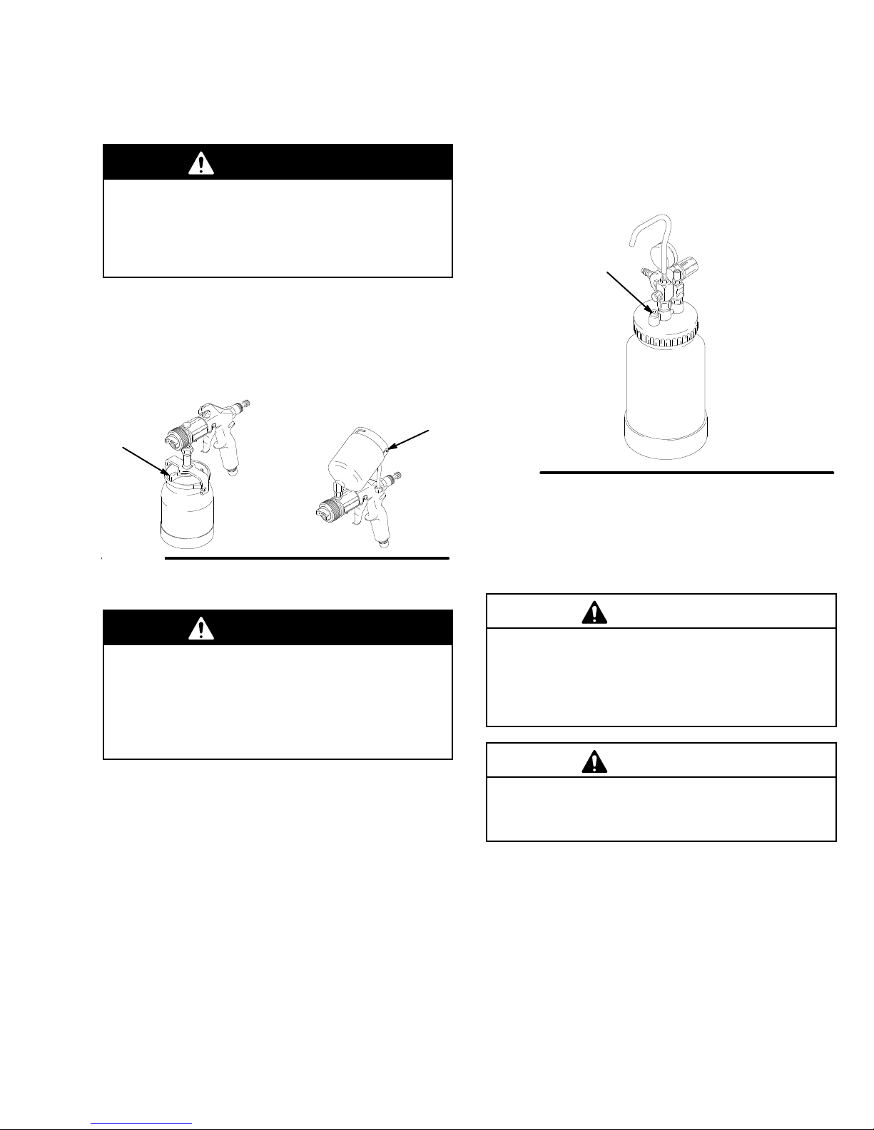
Fill the Cup or Remote Pressure Pot
Spray Gun Cup
WARNING
Setup
b.
2 Quart Remote Pot:
relief knob (1
pressure is completely relieved before remov
ing the cover
system again. See Fig. 3.
13) about one turn. W
. Close the knob before using the
T
urn out the pressure
ait until
-
The spray gun cup is pressurized by the gun’
supply. T
pressurized fluid or accidental spray from the gun,
always turn of
removing the spray gun cup.
Only fill the cup 3/4 full to help keep the air pressure
tube clean, then install the cover
has a latch (H) to secure it to the cup. The over-cup
has a ring with notches (J) that secures the cup hood
into place when locked in place on the cup.
H
Fig. 2
Accessory Remote Pressure Pot
o reduce the risk of serious injury from
f the air supply to the gun before
. The under-cup cover
s air
WARNING
The accessory remote pressure pots remain pres
surized until pressure is manually relieved. T
reduce the risk of serious injury from pressurized
fluid or accidental spray from the gun, always
relieve pressure in the pressure pot before loosen
ing or removing the cover
1.
Relieve the remote pressure pot pressure by
following these steps:
a. T
urn of
f the air supply to the pressure pot.
.
-
o
J
-
113
2 quart
Fig. 3
2. Remove
sure pot. Secure the cover
NOTE:
the cover threads with petroleum jelly
the pressure pot cover and fill the pres
.
2 quart remote pressure pot only:
.
lightly coat
CAUTION
If the 2 quart remote pressure pot is accidentally
tipped over or held at too great of an angle, fluid may
leak into the air regulator
this. If fluid does get into the regulator
immediately.
. T
ake precautions to avoid
, clean it
CAUTION
Do not tighten the pressure pot cover more than
hand-tight. Excessive tightening may damage the
cover gasket.
-
Page 10

Prepare the Surface to be Sprayed
To
achieve proper adhesion, make sure the surface to
be sprayed is completely clean.
Operating the Turbine
WARNING
Sparking
of the turbine motor
from flammable liquid, dust particles and other
flammable substances in the spray area, and
cause serious injury and property damage. Be sure
to follow the precautions below:
D
D
D
D A
can be expected in the normal operation
. Sparks could ignite fumes
When flammable liquid is sprayed or used for
flushing or cleaning equipment, the turbine must
be placed at least 20 feet (6.1 m) away from
areas where hazardous concentrations of
flammable vapors are likely to occur
Use additional air hose if necessary to ensure
that the turbine is operated in a clean, dry
ventilated area.
Never place the turbine inside a spray booth!
Use this equipment outdoors or in extremely
well ventilated areas.
void all ignition sources such as static electric
ity from plastic drop cloths, open flames such as
pilot lights, hot objects such as cigarettes, arcs
from connecting or disconnecting power cords
or turning light switches on and of
or remove all sources of ignition.
.
, well
f. Extinguish
Setup
1. T
NOTE:
period of time, turn it of
automatically.
2.
NOTE: To adjust the spray gun pattern, see the
turbine gun manual 308–336.
Series 800 Cold W
T
urbine Spray Model Series 800 has a diaphragm
compressor
diaphragm will become stiff in cold weather
enough, the stif
sor to start (the unit will hum). If this occurs, follow
these steps:
1. T
2.
3.
-
4.
5.
6.
urn the turbine on a few minutes before you start
spraying to allow for warm-up time.
When the turbine is not in use for an extended
f. The turbine does not shut of
Be sure the turbine filter is clean before operating.
See page 12 to check and clean the filter
eather Operation
. When this compressors is new
f diaphragm will not allow the compres
urn the turbine and compressor of
Unplug the turbine from the power source.
Loosen the four main filter screws and remove the
filter; replace the main filter and pre-filter if they
are dirty
Hand spin the cooling fan on the compressor for a
few revolutions.
Reassemble the turbine.
Plug in the turbine and turn compressor on. The
compressor should start.
.
.
, the
. If cold
f.
f
-
10 308-422
Page 11

Shutdown
Pressure Relief Procedure
WARNING
PRESSURIZED
The equipment stays pressurized until pressure is
manually relieved. To reduce the risk of a serious
injury from pressurized fluid, accidental spray from
the gun, or splashing fluid, follow the
lief Procedure
D
are instructed to relieve the pressure,
D
stop spraying,
D
check or service any of the system equipment,
D
or install or clean the fluid nozzles.
1.
When spraying is finished, release the gun trigger
and turn of
2. T
urn of
f the turbine sprayer
EQUIPMENT HAZARD
Pressure Re
whenever you:
f the air supply to the gun.
.
b.
2 Quart Remote Pot:
relief knob (1
pressure is completely relieved before remov
ing the cover
system again.
See Fig. 4.
-
13) about one turn. W
. Close the knob before using the
113
T
urn out the pressure
2 quart
ait until
-
WARNING
The turbine hose outlet may be hot. Carefully
check the hose end before removing the hose.
3.
If using a remote pressure pot,
by following these steps:
a. T
urn of
f the air supply to the pressure pot.
relieve its pressure
Fig. 4
NOTE: Elevate the spray gun and pull the trigger
will allow the fluid in the fluid hose to drain back into
the remote pressure pot.
4.
Clean the spray gun and cup as instructed in the
turbine gun manual, 308–336.
. This
308-42211
Page 12

Maintenance
Daily
Check
the main turbine filter daily for cleanliness.
The turbine systems are lifetime lubricated. The only
maintenance required is filter cleaning and replace
ment.
The turbine main filter and pre-filter must be clean at
all times to provide suf
and atomize the fluid. Check the filters weekly
mum. Replace the pre-filter as required.
ficient air flow to cool the motor
-
, mini
CAUTION
Do not operate the turbine sprayer without the filter
installed.
-
NOTE: To check the filter
place a piece of paper against the air intake filter
air intake holds the paper in place, the filter is okay
T
o clean the main filter:
1. T
urn of
f and unplug the turbine.
2.
Loosen the four main filter screws. See Fig. 5.
3.
Remove the main filter and clean it by following
one of the following three methods:
D T
ap the filter gently on a flat surface, dirty side
down.
D
Direct compressed air (100 psi [7 bar] maxi
mum) through the filter panel in the opposite
direction of the arrows on the side of the filter
D
Soak the filter for 15 minutes in water and a
mild detergent. Rinse the filter until it is clean.
Air dry the filter; do not use compressed air
, turn on the turbine and
. If the
WARNING
T
o avoid damage to the turbine and possible elec
tric shock, never install a damp filter in the turbine.
.
Main
filter
screws
03072
Fig. 5
Series 800 T
urbine shown
Weekly
-
.
Check the hose for cracks, leaks, and holes. Replace,
if necessary
.
Annually or 600 Hours (whichever comes
first)
.
-
Replace
sprayer operation. If the brushes are not replaced,
motor failure will occur
NOTE:
center perform the motor brush replacement. See the
procedure on page 16.
the motor brushes 600 hours after turbine
.
It is recommended that an authorized service
12 308-422
Page 13

Troubleshooting
PROBLEM CAUSE SOLUTION
Remote Container Pressurization
(Series
to
800) Compressor fails
start
No
fluid delivery
Cold weather operation.
. Check for leaks at the container gasket,
2
quart lid, and 2 1/2 gal pot wing nuts.
Check for air flow from male quick–disconnect at compressor outlet (approx.
1/4 CFM).
Turn
pressure regulator clockwise. Look
for
pressure on gauge. (If no pressure on
gauge,
Check
needle
Check
Check if fluid pickup tube is unplugged.
Tighten.
Blow
Check container for material.
See Cold W eather Operation instructions,
check air line and fittings).
hole in tank lid under regulator or
valve 2 Qt lid. Clean if necessary
for obstructions.
out and clear material hose.
page 10.
.
T
urbine fails to start
Poor atomization
Red Rocker Circuit Breaker
Switch Trips
Power supply
Dirty filter
Extension cord too long.
Hose length too long.
Check filter
Excessive high ambient temperature.
Excessive brush wear
Excessive current draw
.
.
.
.
.
Cycle red rocker switch.
Clean filter
Replace with shorter extension cord (do
not exceed 100 ft). Extension cord must
3-wire, 12 A
be
Replace with shorter hose. See Accessories
Clean filter and replace as necessary
Move turbine to cooler area.
Remove turbine wrapper and:
. Check for free motor rotation,
. Check brush wear
. Replace motor brushes if necessary
Return to authorized service center
.
WG.
for shorter hose and P/N.
.
,
.
.
308-42213
Page 14

WARNING
Turn
of
f turbine and unplug power for the following
procedures.
T
urbine Switch Replacement (Red Rocker Circuit
Breaker)
o remove the turbine switch (3), wedge a large
1. T
flat blade screwdriver between the top of the
switch and the turbine face plate. See Fig. 6.
2.
Push down firmly on the switch. Pry the switch out
far enough so the two top switch locking tabs are
visible.
While maintaining outward pressure on the switch,
3.
push down on the two locking tabs with a small flat
blade screwdriver until they release. The switch
will pop out.
4.
Disconnect the two wires and remove the switch.
5.
Reinstall by connecting wires to the new switch.
Snap the switch into place.
Repair
6.
7.
rapper Removal
W
Remove the cabinet wrapper by following these steps.
1.
2.
3.
4.
5.
NOTE:
Reinstall the hose on the “out” side of the com
pressor.
Replace the main filter
Remove the four filter screws. Remove the main
filter
. Clean and replace the filter if necessary
Remove the four remaining top wrapper screws.
Do not remove handle screws.
Remove one screw from each side of the wrap
per.
Remove the four remaining bottom wrapper
screws. Do not remove the rubber feet.
Gently pry loose and remove the wrapper from the
cabinet.
The wrapper is sealed with caulk.
.
-
.
-
Locking Tabs
3
Fig. 6
Series 800 Compressor Replacement
1.
Remove the four main filter stop screws and
remove the main filter
necessary).
Remove the air hose from the “out” side of the
2.
compressor.
Locate and remove the three compressor hold–
3.
down screws.
4.
Remove the ground screw
remove the compressor
Rewire and install the new compressor
5.
removable LoctiteR on the compressor screws and
tighten the screws. Do not overtighten the rubber
bumpers.
14 308-422
. (Clean or replace filter as
. Clip the lead wires and
.
. Apply
03728
Filter
Screws
Wrapper
Screws
Side
Fig. 7
Power Cord Replacement
Remove the cabinet wrapper by following the
Removal
The power cord may now be replaced.
Series 800 Compressor T
ment
Remove the cabinet wrapper by following the
Removal
The compressor toggle switch (Series 800) may now
be replaced.
procedure.
procedure.
Series 900 shown
oggle Switch Replace
Screws
03067
Wrapper
-
Wrapper
Page 15

Repair
Turbine/Motor
The Series 700 and 800 turbine replacement kit
M73525 contains: T
spacer (16), foam fan seal (83), ground ring terminal
(7) red butt connector (not shown, used on series 800
only) and 2 switch connectors (8)
The Series 900 turbine replacement kit M73526 con
tains: T
foam fan seal (83), ground ring terminal (7) and 2
switch connectors (8)
Remove the cabinet wrapper by following the steps in
the W
list exploded view for disassembly
Note:
1.
2.
3.
urbine unit (62), rubber bottom spacer (16),
rapper Removal procedure. Reference the parts
the wrapper is sealed with caulk.
The motor may now be replaced.
Remove the upper motor mount (42) by removing
the five screws that retain it.
Remove the ground wire (green) and switch wires
(black & white).
Replacement
urbine unit (62), rubber bottom
-
.
Be sure to install the ground wire to the grounding
7.
stud on the lower motor mount.
8.
Replace the upper motor mount and the five
screws that retain it.
9.
Install the new fan seal gasket (83) on the top of
the upper motor mount
10.
Replace the wrapper and filter system.
Motor
Black
61
60
Green
White
8
White
7
8
9
Green
Black
Rocker
Switch
Power
Cord
Note:
Series 800 only
approximately 2 in. from the three wire crimp connec
tor.
4.
Install (crimp) the female switch connectors or red
butt connectors on the new turbine as shown in the
appropriate wiring diagram. The round ring con
nector always goes on the green wire.
Note:
On Series 800 only
(attached to the three wire crimp connector) back
approximately 3/8 in. and install the red butt connector
5.
Remove the old motor from the lower mount by
removing the three bolts (54). The nuts are at
tached to the lower mount, a holding wrench is not
required.
6.
Reinstall the new turbine (62) and pad (16).
Note:
Application of removable Loctiter is recom
mended on the threads of the three bolts (54).
Note:
Do not over tighten the three bolts (54) securing
the turbine to the lower motor mount, damage to the
turbine may occur
, clip the neutral lead (white)
-
-
, strip the white neutral wire
-
-
.
Series 700 shown
Fig. 8
Compressor
Motor
22
61
60
8
.
6
White
Black
Green
Fig. 9
Green
White
79
12
Series 800 shown
White
Rocker
Switch
Black
Green
Black
Black
Power
Cord
T
Switch
78
8
78
Black
oggle
03733A
308-42215
Page 16

Motor
Black
Repair
Motor Brush Replacement
NOTE:
performed by an authorized service center
1.
It is recommended that this procedure be
.
Follow the steps for removing the motor in the
Motor Replacement procedure.
Green
White
White
Fig.
10
2.
On the Series 700 and 800 turbine motor
the two retaining clips and plastic fan cover
Rocker
Switch
7
8
9
Series 900 shown
Green
Black
8
Power
Cord
03735A
On the Series 900 turbine motor
3.
clips out of the top of the motor for brush replace
ment.
4.
Remove the brushes. Check the commutator for
excessive wear
5.
Reassemble the new motor brushes using reverse
order
. Keep lead wires from all rotating parts and
the motor frame.
.
, lift the retaining
CAUTION
Do not run the motor with the air inlet or outlet
sealed of
6.
7.
f.
Reinstall the motor in the reverse order
After running the motor for 30–45 minutes at
full–rated voltage, the motor will return to full
performance.
, remove
.
-
.
16 308-422
Page 17

Notes
308-42217
Page 18

Parts
for Series 700
35
34
33
26
93
39
38
37
20
43
36
60
62
42
8
21,
51
7
28
29
31
30
83
50
8
54
53
45
27
26
3
16
6
5
9
7
4
84
93
10
59
17
88
85
24
25
94
86
04959A
18 308-422
Page 19

Parts
Ref
No.
3 M70657
4 M70601
5 106013
6 107260 CONNECT
7 102799
8 M70760
9 107266 CONNECT
10 M73044 PLA
16 M73323 P
17 M70773 W
20 M73043 WRAPPER 1
21 M73024
24 M70763 BUMPER 4
25 M70775 SCREW
26 M70774 SCREW
27 M73048 PLA
28 M70859 FIL
29 M70757 FIL
30 M71558 FIL
31 M70607 FIL
33 M71628
34 M70872 NUT
35 M70874 W
36 M71246 O-RING 1
37 M71262
Part No.
Description Qty
SWITCH, rocker 12A
CORD, power
FITTING, strain relief
OR, female
TERMINAL, ground ring
SWITCH, connector
OR, male
TE, face
AD, turbine mount
ASHER, 1/4
DECAL, RH
, 8–32x5/8
, black oxide, 8–32x1/2
TE, bottom
TER, stop
TER, foam stop
TER KIT
TER, pre
FOAM, die cut
, cabinet handle
ASHER, 3/16x1
FITTING, air outlet
, main
, female
for Series 700
20
Ref
No.
38 M70870
1
39 M70873 SCREW
1
42 M73009 MOUNT
1
43 M70776 NUT
1
45 M73019 SP
1
50 113400 SCREW 3
2
51 M73025
1
53 M70764 O-
1
RING 3
1
54 M73021 BOLT
6
59 M71012 MOUNT
60 M73503
1
61 M71185 SCREW
62 M73525* MOT
4
82 186620
83 M73362 GASKET
1
84 M71452
1
85 M71681** VAL
4
86 M70402 DISCONNECT
1
88 M70721
1
93 M71603
2
94
2
2
*
gaskets, and electrical connectors. Motor Brush Kit M73521
1
is also available. Purchase separately
** V
Part No.
Motor Kit M73525 includes: motor
alve Kit M71681 includes air valve and o–ring.
Description Qty
HANDLE,
, cabinet handle
, turbine upper
, hex
ACER, 2.9
DECAL, LH (not shown)
, 1/4–20x4.00
, turbine lower
WIRE, green/yellow
, self–tapping
OR KIT
LABEL, ground (not shown)
HOSE, turbine, 25 ft
VE, turbine air
O-RING, hose
LABEL, Danger/W
GUN, T
Manual, 308–336
, Series 700, 120V
, fan seal
, quick
arning 1
urbine, see Gun Instruction
, ground wire connectors,
.
1
2
1
2
3
1
3
1
1
1
1
1
1
1
1
1
1
1
61
60
Green
White
White
8
9
Motor
7
Green
Black
Black
Rocker
Switch
8
6
Power
Cord
03732A
308-42219
Page 20

Parts
for Series 800
35
34
33
93
26
89
31
24
25
32
27
26
M70962
(see
page 24)
38
39
30
29
42
21,
51
20
37
58
2
1
3
89
1
61
60
62
6
36
43
16
28
83
50
54
53
45
59
17
8
5
7
4
84
52
10
92
85
95
96
04960A
Page 21

Parts for Series 800
Ref
No.
1 M70603
2 M70811
3 M70657
4 M70601
5 106013
6 M70759 CONNECT
7 102799
8 M70760
10 M73045 PLA
12 M71143
16 M73323 P
17 M70773 W
20 M73043 WRAPPER 1
21 M73026
24 M70763 BUMPER 4
25 M70775 SCREW
26 M70774 SCREW
27 M73285 PLA
28 M70859 FIL
29 M70757 FIL
30 M71558 FIL
31 M70607 FIL
32 M71535 {
33 M71628
34 M70872 NUT
35 M70874 W
36 M71246 O-RING 1
37 M71262
38 M70870
39 M70873 SCREW
42 M73009 MOUNT, motor
43 M70776 NUT
Part No.
Description Qty
SWITCH, toggle
SWITCH, plate
SWITCH, rocker 12 amp
CORD, power
FITTING, strain relief
OR, red butt
TERMINAL, ground ring
SWITCH, connector
TE, face
HARNESS, 14 in wire
AD, turbine mount
ASHER, 1/4
DECAL, RH
, 8–32x5/8
, black oxide 8–32x1/2
20
TE, bottom
TER, stop
TER, foam stop
TER KIT
, main
TER, pre
COMPRESSOR KIT
,
Series 800, 120V
FOAM, die cut
, cabinet handle
ASHER, 3/16x1
FITTING, air outllet
HANDLE,
, cabinet handle
, upper
, hex
Ref
No.
1
45 M73019 SP
1
50 113400 SCREW 3
1
51 M73027
1
52 M71136 WASHER 3
1
53 M70764 O-RING 3
1
54 M73021 BOLT
1
58 M70673
2
60 M73503
1
61 M71185 SCREW
1
62 M73525 *MOT
1
78 M71187
6
79 M70810 CONNECT
82 186620
1
83 M73362 GASKET
84 M71452
4
85 M70721
89 M70691
1
92 M70402 DISCONNECT
1
93 M71603
4
95 M71631
1
1
96
1
2
*
2
gaskets, and electrical connectors. Motor Brush Kit M73521
2
is also available. Purchase separately
1
** Unloader Kit M70691 includes unloader valve, hose, hose
1
clamps and fitting M70809.
Part No.
Description Qty
ACER, 2.9 in.
DECAL, LH (not shown)
, 1/4–20x4.00
COUPLING, parker #207P–4
WIRE, green/yellow
, self–tapping
OR KIT
WIRE, black
OR, crimped
LABEL, ground (not shown)
, fan seal
HOSE, turbine, 25 ft
O-RING, hose
**UNLOADER KIT
LABEL, warning/danger
HOSE, compressed air
disconnect, 25 ft
GUN, turbine, see Gun Instruction
Manual, 308–336
Motor Kit M73525 includes: motor
, Series 800, 120V
, quick
, ground wire connectors,
.
2
1
{
Compressor Kit, M71535, includes compressor
3
wire, and electrical connectors.
3
1
3
1
1
1
1
2
2
1
1
1
1
1
1
1
, with quick
1
1
, ground
Compressor
Green
8
White
Black
12
61
60
Green
White
79
Motor
White
Green
Black
Black
Rocker
Switch
Black
Black
Power
Cord
Toggle
Switch
78
8
78
03733A
308-42221
Page 22

Parts
for Series 900
35
34
33
26
93
39
38
20
82
62
36
37
31
30
29
28
21,
51
8
7
8
42
50
54
17
53
45
17
83
27
44
43
26
3
16
59
6
5
7
9
4
84
10
85
87
86
24
25
94
04961A
Page 23

Parts
Ref
No.
3 M70657
4 M70601
5 106013
6 107260 CONNECT
7 102799
8 M70760
9 107266 CONNECT
10 M73046 PLA
13 M71179
16 M73039 P
17 M70773 W
20 M73043 WRAPPER 1
21 M73028
24 M70763 BUMPER 4
25 M70775 SCREW
26 M70774 SCREW
27 M73048 PLA
28 M70859 FIL
29 M70757
30 M71558 FIL
31 M70607 FIL
33 M71628
34 M70872 NUT
Part No.
Description Qty
SWITCH, rocker 12 amp
CORD, power
FITTING, strain relief
OR, female
TERMINAL RING, ground
SWITCH, connector
OR, male
TE, face
WIRE, tie (not shown)
AD, turbine mount
ASHER, 1/4
DECAL, R.H.
, 8–32x5/8
, black oxide, 8–32x1/2
TE, bottom
TER, stop
FOAM, filter stop
TER KIT
TER, pre
FOAM, die cut
, cabinet handle
, main
for Series 900
16
Ref
No.
35 M70874 W
1
36 M71246 O-RING 1
1
37 M71262
1
38 M70870 HANDLE 1
1
39 M70873 SCREW
2
42 M73011 MOUNT, motor
2
43 M70776 NUT
1
44 M70789 SCREW
1
45 M73020 SP
1
50 113400 SCREW 3
1
51 M73029
6
53 M70764 O-RING 3
54 M70770 BOLT
1
59 M73010 MOUNT, motor
62 M73526* MOT
4
82 186620
83 M73037 GASKET
1
84 M71452
1
85 M71681** VAL
4
86 M70402 DISCONNECT
1
87 M70721
1
93 M71603
2
94
2
Part No.
Description Qty
ASHER, 3/16x1
FITTING, air outlet
, cabinet handle
, upper
, hex
, 1/4 x 20 x 3/4
ACER, 2.6
DECAL, LH
, 1/4–20x3.5
, lower
OR KIT
LABEL, ground (not shown)
, fan seal
HOSE, 25 ft
VE, turbine air
, quick
O-RING, hose
LABEL, warning/danger
Gun, turbine, see Gun Instruction
Manual, 308–336
2
1
2
1
3
4
3
1
3
1
1
1
1
1
1
1
1
1
Green
White
White
*
Motor Kit M73526 includes: motor
gaskets, and electrical connectors. Motor Brush Kit M73522
is also available. Purchase separately
alve Kit M71681 includes air valve and o-ring.
** V
Motor
Black
Rocker
8
7
8
9
Green
Black
6
Switch
Power
Cord
, ground wire connectors,
.
03735A
Page 24

Accessories
2-1/2
Gallon (9.46 liter) Pressure Pot M70604
(Series 800 only)
50 psi (3.5 bar) Maximum Inlet Air Pressure
2-1/2 gallon (9.46 liter) capacity
an air pressure regulator and gauge and a pressure
relief valve.
201
216
217
202
212
204
205
NOTE:
2 1/2 Gal
(9.46 liter) Paint
T
ank Liner (5
pak) M70695
, steel tank. Includes
221
208
209
203
207
212
2
Quart (1.94 liter) Pressure Pot M70962
(Series 800 only)
50 psi (3.5 bar) Maximum Inlet Air Pressure
2 quart (1.94 liter) capacity
, aluminum cup.
Includes an air pressure regulator and gauge, pressure
relief valve, and rigid hook handle.
WARNING
Do not use 1,1,1-trichloroethane, methylene chlo
ride, other halogenated hydrocarbon solvents or
fluids containing such solvents in the turbine spray
system, which contains aluminum and/or galva
nized-coated parts. Such use could result in a
serious chemical reaction, with the possibility of
explosion, which could cause death, serious injury
and/or substantial property damage.
*109
118
101
121
124
120
119
114
-
-
,
103
102
123
122
128
Ref.
No. Part No. Description Qty.
201 104655 PRESSURE GAUGE 1
202 151519
203 M70687 COUPLING 1
204 M70676 O-RING 1
205 M70686 PRESSURE RELIEF VALVE 1
207 M70616 GASKET
M70617 GASKET
208 M70678 WING NUT 5
209 M70677 WASHER 5
212 M71433 T
216 169969 QUICK DISCONNECT
217 104815 PRESSURE REGULATOR 1
221 M71639 HANDLE 1
REDUCER, 1/4 to 1/8
, standard; EPDM
, solvent resistant; Thiokol
(optional–must order separately)
ANK, paint, 2-1/2 gallon (9.5 liter),
with cover
, black powder coat
, male
04957
109
112
126
127
Ref.
No. Part No. Description Qty.
101 104655 PRESSURE GAUGE 1
1
102 M70727 SAFETY VALVE 1
103 104815 PRESSURE REGULATOR 1
109 M71144 POT
112 M71425 GASKET KIT
1
114 M70725 FITTING 1
118 169969 QUICK DISCONNECT
1
119 M71491
120 M71470
121 M70854 HOSE CLAMP 1
122 110440
1
123 189557 RESTRICTOR 1
1
124 M70399 QUICK DISCONNECT
126 M71681 AIR VAL
127 M70402 QUICK DISCONNECT 1
128 M72842 FITTING, air pressure stem 1
*NOTE: Handle is shipped loose, inside the 2 qt container
, 2 quart (1.94 liter), aluminum
, polyethylene (5 pak)
, male
HOSE, fluid; 60 in. long; 1/4 in. ID
HOSE, air; 54 in. (1.37 m) long
FITTING. tee
, male
VE KIT (o–ring and valve)
02951A
1
1
1
1
1
1
1
1
.
Page 25

Accessories
NOTE: See selection charts in the gun turbine manual,
308–336, to order fluid sets.
Lubricant 111–265
One 4 oz. (1
lubricant for fluid seals and wear areas.
#4 Ford V
Used to measure viscosity of fluid.
1 Quart Cup Lid M70610
Fits on 1 qt under–cup for air tight storage of fluid.
1 Quart Cup M71667
1 quart under-cup.
1 Quart Cup Gaskets M70425
5 pack of polyethylene gaskets for use with 1 quart
under-cup.
1 Quart Under-Cup Assembly M71660
Complete 1 quart under-cup assembly
13 gram) tube sanitary (non-silicone)
iscosity Cup M70702
.
Automotive User Kit M70705
For use with automotive finishes. Includes:
Part No.
M70559
M70647
M70425
M70464
M70395
–
T
rail Around Dolly M70700
Lightweight and mobile platform with wheels; for use
with Series 700, Series 800, and Series 900.
45 Degree Elbow M70593
Attaches between gun and turbine air hose; increases
maneuverability.
Y Fitting Kit M70611
Creates two air connections; allows for two–gun
operation.
Series 800 1/4 in. ID Compressor Air Hose (with
Female Quick Disconnect)
PVC, Maximum W
Part No.
M70665
M71631
Description
1.0/0.05 mm Fluid Set
1.2/0.7 mm Fluid Set
1 Quart Under-cup Gaskets (5-pack)
Fluid Strainer
Upper Air Pressure Hose
Parts Box with Compartments
orking Pressure: 150 psi (10.3 bar)
Length
20 ft
25 ft
(Extension)
(Replacement)
Cup Check V
T
o help prevent the cup from depressurizing after the
air is shut of
Fluid Strainer M70464
Install on the end of the cup or pressure pot fluid tube
to strain the fluid and help eliminate surface blemishes
and plugged tips. 100 mesh screen.
Blow Gun M70703
For dusting and drying. With quick disconnect.
Contractor User Kit M70704
Used for fine finish materials and heavier bodied
materials (latex). Includes:
Part No.
M70562
M70582
M70425
M70464
M70395
–
alve M71007
f.
Description
1.0 mm Fluid Set
2.0 mm Fluid Set
1 Quart Under-cup Gaskets (5-pack)
Fluid Strainer
Upper Air Pressure Hose
Parts Box with Compartments
3/8 in. ID Paint Fluid Hose
LDPE, Maximum W
Part No.
M71482
M71481
M71484
M71486
M71485
Material Hose Connector M70693
For use with 3/8 in. paint fluid hose.
3/4 in. ID T
PVC, Maximum W
Part No.
M71452
M71453
M71454
M71455
3/4 in. ID T
Spring
PVC, Maximum W
Part No.
M71460
M71461
M71462
M71463
M71464
urbine Air Hose with Spring
urbine Air Hose Extension without
orking Pressure: 175 psi (12 bar)
Length
15 ft
25 ft
30 ft
40 ft
50 ft
orking Pressure: 100 psi (6.9 bar)
Length
25 ft
30 ft
40 ft
50 ft
orking Pressure: 100 psi (6.9 bar)
Length
10 ft
15 ft
20 ft
25 ft
30 ft
Page 26

Notes
Page 27

Notes
Page 28

The
WARRANTY
Graco
warrants all equipment manufactured by it and bearing its name to be free from defects in material and workmanship on
the date of sale
warranty,
tive.
ommendations.
This warranty does not cover
misapplication, abrasion, corrosion, inadequate or improper maintenance, negligence, accident, tampering, or substitution of
non–Graco component parts. Nor shall Graco be liable for malfunction, damage or wear caused by the incompatibility with Graco
equipment of structures, accessories, equipment or materials not supplied by Graco, or the improper design, manufacture, instal
lation, operation or maintenance of structures, accessories, equipment or materials not supplied by Graco.
This warranty is conditioned upon the prepaid return of the equipment claimed to be defective to an authorized Graco distributor
for verification of the claim. If the claimed defect is verified, Graco will repair or replace free of charge any defective parts. The
equipment will be returned to the original purchaser transportation prepaid. If inspection of the equipment does not disclose any
defect in material or workmanship, repairs will be made at a reasonable charge, which charges may include the costs of parts,
labor and transportation.
DISCLAIMERS AND LIMITATIONS
The terms of this warranty constitute purchaser’s sole and exclusive remedy and are in lieu of any other warranties (express or
implied),
liabilities, including product liabilities, based on negligence or strict liability
tial damages or loss is expressly excluded and denied. In no case shall Graco’
Any action for breach of warranty must be brought within two (2) years of the date of sale.
Graco will, for a period of twelve months from the date of sale, repair or replace any part of the equipment proven defec
This warranty applies only when the equipment is installed, operated and maintained in accordance with Graco’
including warranty of merchantability or warranty of fitness for a particular purpose
Graco Warranty and Disclaimers
by an authorized Graco distributor to the original purchaser for use. As purchaser’s sole remedy for breach of this
s written rec-
, and Graco shall not be liable for
, any malfunction, damage or wear caused by faulty installation,
, and of any non–contractual
. Every form of liability for direct, special or consequen
s liability exceed the amount of the purchase price.
-
-
-
EQUIPMENT NOT COVERED BY GRACO WARRANTY
Graco makes no warranty
respect to accessories, equipment, materials, or components sold but not manufactured by Graco. These items sold, but not
manufactured by Graco (such as electric motor
Graco will provide purchaser with reasonable assistance in making any claim for breach of these warranties.
TO
PLACE AN ORDER
1–800–328–0211 T
, and disclaims all implied
, switches, hose, etc.) are subject to the warranty
Graco
, contact your Graco distributor
oll Free
warranties of merchantability and fitness for a particular purpose
, if any
, of their manufacturer
Phone Number
, or call this number to identify the distributor closest to you:
, with
.
Sales
Foreign Offices:
Belgium, Canada, England, Korea, Switzerland, France, Germany
Offices:
GRACO INC. P.O. BOX 1441
PRINTED
IN U.S.A. 308–422 June 1994 Revised January 1996
Atlanta, Chicago, Detroit, Los Angeles
MINNEAPOLIS, MN
, Hong Kong, Japan
55440–1441
 Loading...