

Graco LubePro H1900, LubePro 24Y498, LubePro 24Y499, LubePro 25Y499, LubePro 25Y498 Instructions Manual
Instructions
™
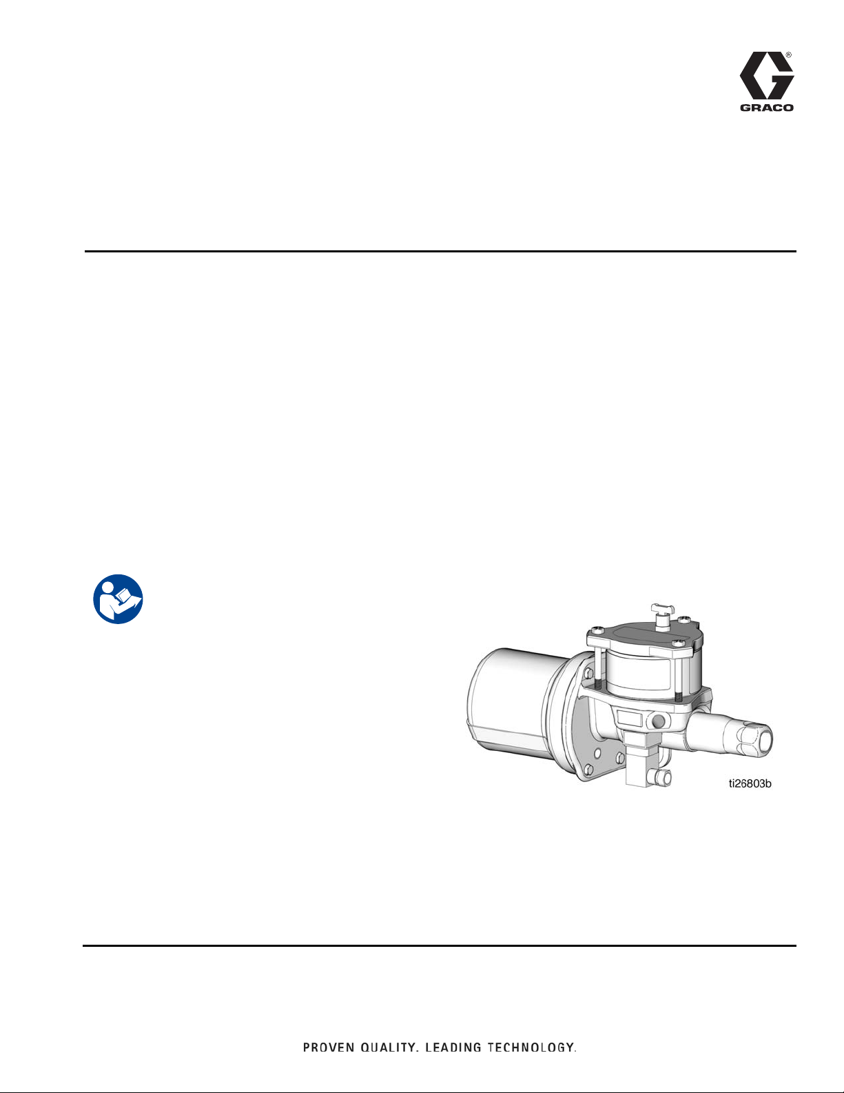
H1900 LubePro
3A3169E
Oil Pump
For pumping non-corrosive and non-abrasive lubricants only. For professional use only.
Not approved for use in explosive atmospheres or hazardous locations.
Model No.
24Y498 - 19:1 Oil pump without Low Level
24Y499 - 19:1 Oil pump with Low Level
25Y498- 19:1 Oil pump without Low Level, includes BSPP adapter
25Y499 - 19:1 Oil pump with Low Level, includes BSPP adapter
EN
80 psi (0.55 MPa, 5.5 bar) Maximum Oil Input Pressure
3500 psi (24 MPa, 241 bar) Maximum Working Pressure
Important Safety Instructions
Read all warnings and instructions in this manual.
Save these instructions.
Warnings
WARNING
WARNINGWARNING
Warnings
The following warnings are for the setup, use, grounding, maintenance, and repair of this equipment. The exclamation point symbol alerts you to a general warning and the hazard symbols refer to procedure-specific risks. When
these symbols appear in the body of this manual or on warning labels, refer back to these Warnings. Product-specific
hazard symbols and warnings not covered in this section may appear throughout the body of this manual where
applicable.
PRESSURIZED EQUIPMENT HAZARD
Over-pressurization can result in equipment rupture and serious injury.
• Do not exceed the maximum oil inlet pressure.
• Do not exceed the maximum air input pressure.
• Use tubing, hoses and other components with pressure ratings equal to or higher than the pump
rating.
SKIN INJECTION HAZARD
High-pressure fluid from dispensing device, hose leaks or ruptured components will pierce skin. This
may look like just a cut, but it is a serious injury that can result in amputation. Get immediate surgi-
cal treatment.
• Do not point dispensing device at anyone or at any part of the body
• Do not put your hand over the fluid outlet.
• Do not stop or deflect leaks with your hand, body, glove, or rag.
• Follow the Pressure Relief Procedure when you stop dispensing and before cleaning, checking,
or servicing equipment.
• Tighten all fluid connections before operating the equipment.
• Check hoses and couplings daily. Replace worn or damaged parts immediately.
EQUIPMENT MISUSE HAZARD
Misuse can cause death or serious injury.
• Do not operate the unit when fatigued or under the influence of drugs or alcohol.
• Do not exceed the maximum working pressure or temperature rating of the lowest rated system
component. See Technical Data in all equipment manuals.
• Use fluids and solvents that are compatible with equipment wetted parts. See Technical Data in
all equipment manuals. Read fluid and solvent manufacturer’s warnings. For complete information
about your material, request Safety Data Sheet (SDS) from distributor or retailer.
• Turn off all equipment and follow the Pressure Relief Procedure when equipment is not in use.
• Check equipment daily. Repair or replace worn or damaged parts immediately with genuine manufacturer’s replacement parts only.
• Do not alter or modify equipment. Alterations or modifications may void agency approvals and create safety hazards.
• Make sure all equipment is rated and approved for the environment in which you are using it.
• Use equipment only for its intended purpose. Call your distributor for information.
• Route hoses and cables away from traffic areas, sharp edges, moving parts, and hot surfaces.
• Do not kink or over bend hoses or use hoses to pull equipment.
• Keep children and animals away from work area.
• Comply with all applicable safety regulations.
2 3A3169E
Warnings
WARNING
WARNINGWARNING
MOVING PARTS HAZARD
Moving parts can pinch, cut or amputate fingers and other body parts.
• Keep clear of moving parts.
• Do not operate equipment with protective guards or covers removed.
• Pressurized equipment can start without warning. Before checking, moving, or servicing equipment, follow the Pressure Relief Procedure and disconnect all power sources.
TOXIC FLUID OR FUMES HAZARD
Toxic fluids or fumes can cause serious injury or death if splashed in the eyes or on skin, inhaled, or
swallowed.
• Read Safety Data Sheet (SDS) to know the specific hazards of the fluids you are using.
• Store hazardous fluid in approved containers, and dispose of it according to applicable guidelines.
PERSONAL PROTECTIVE EQUIPMENT
Wear appropriate protective equipment when in the work area to help prevent serious injury, including eye injury, hearing loss, inhalation of toxic fumes, and burns. Protective equipment includes but is
not limited to:
• Protective eyewear, and hearing protection.
• Respirators, protective clothing, and gloves as recommended by the fluid and solvent manufacturer.
3A3169E 3
Installation
J
B2
B1
F
B3
C
D
H
K
G
L
A
M
E
N
R
P
S
T
W
U
AA
V
Y
CC
EE
DD
UU
UU
UU
BB
Installation
Typical Installation
Throughout this manual, reference letters used in the instructions, refer to the reference letters used in the Typical
Installation illustration shown in F
IG. 1.
FIG. 1: Typical Installation
4 3A3169E
Installation
RT
GW
GS
Typical Installation Key:
A Main air supply
B Filter/Regulator/Lubricator Assembly
B1 - Air Filter
B2 - Air Regulator
B3 - Air Lubricator
C Air solenoid valve (4-way)
D Pump module
E Pump outlet
F Bleed-type master air valve (required)
G High pressure lubricant supply lines (user supplied)
HInjector
J Lubricator controller
K Pump reservoir
L Pump reservoir cover
M Ground
N Pump outlet check body
P Pump air inlet - forward stroke
R Pump air inlet - return stroke
S Feeder lines
TLow level
U Pressure reducing valve (required in systems over 80 psi
(0.55 MPa, 5.5 bar)
V Supply line shut-off valve (required)
WDrum
Y Pressure gauge
AA Bung adapter
BB Cock valve
CC Oil input supply line
DD Oil input supply pump/system
EE Drain hose
UU Air supply lines
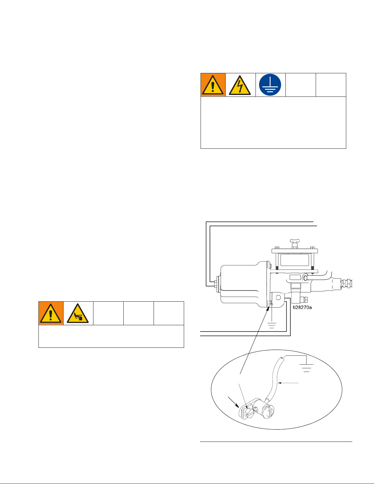
Grounding
Grounding is necessary when voltages above 30
VAC or 42 VDC are used for the low level switch or
for an air valve attached to the pump. Improper
grounding can cause electric shock. Grounding
reduces the risk of electric shock by providing an
escape wire for the electric current in the event of
malfunction or breakdown.
To ground the pump: Remove the ground screw (GS)
located on the back of the pump base and insert it
through the eye of the ring terminal (RT) at end of
ground wire (GW). Fasten the ground screw (GS) back
onto the pump and tighten securely. Connect the other
end of the ground wire to a true earth ground. See F
2.
IG.
Mounting
Mount pump securely so it cannot move around
during operation. Failure to do so could result in personal injury and/or equipment damage.
Install the pump in a location that will adequately support the weight of pump when filled with lubricant and
also provides easy operator access to the pump air controls. Pump must be mounted in a vertical position with
the reservoir up.
See Technical Data, page 31 for pump weight information and the Dimensions and Mounting layout, page 30.
3A3169E 5
FIG. 2
Installation
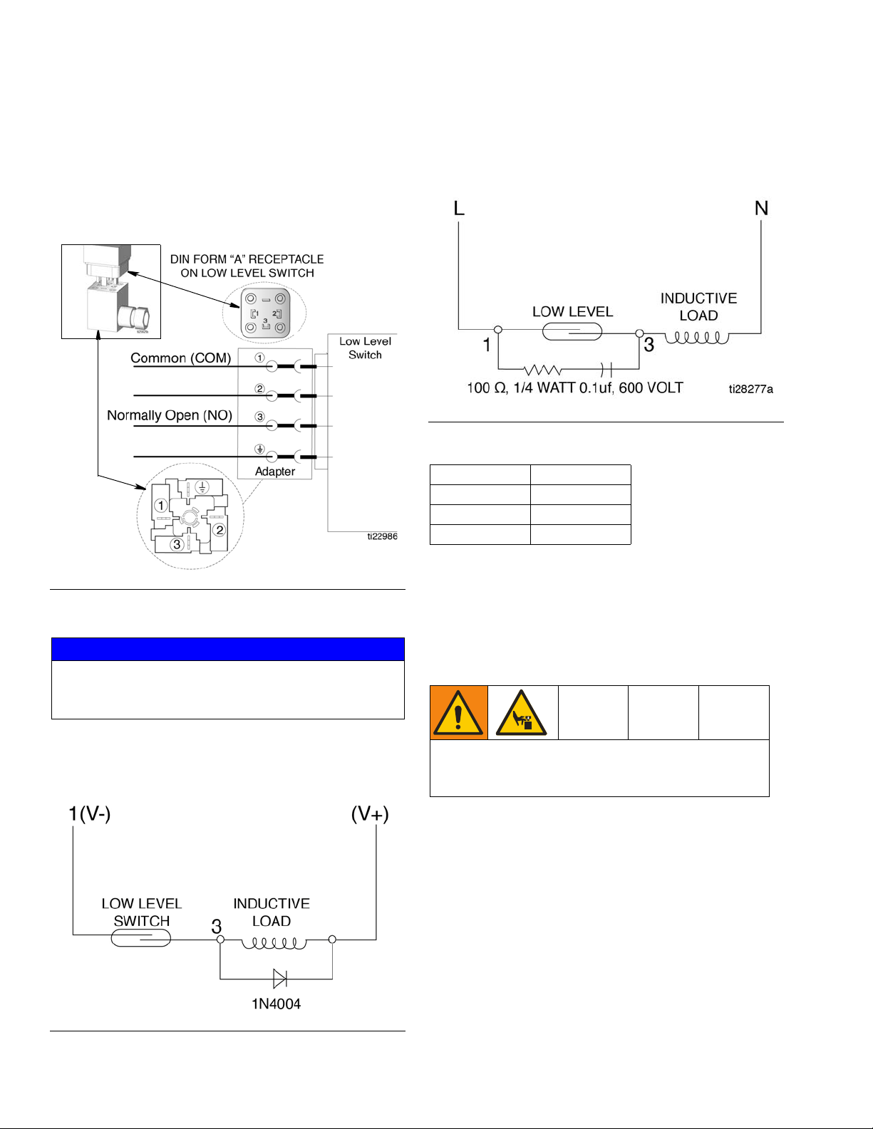
Low Level Models Only
DIN Connector
Connection is made to PINS 1 and 3 of the DIN Field
Wireable Connector. See F
page 31 for electrical ratings.
IG. 3. See Technical Data,
AC Voltage - A resistor and capacitor (high impedance
60 hertz) connected in parallel with the switch, as shown
in F
IG. 5, is recommended.
FIG. 5
Switch Ratings
Volts Amps
30 0.3
120 0.13
240 0.06
FIG. 3
Recommended Protection
NOTICE
Connecting the low level switch directly to the load
may weld the contacts or erode the contact surface,
resulting in a shorter switch life.
DC Voltage - A 1N4004 diode (or equivalent) connected
cathode-to-positive, shown in F
IG. 4, is recommended.
Air and Fluid Line Accessories
Install the air line accessories in the order shown in FIG.
1, page 4.
Trapped air can cause the pump to cycle unexpectedly, which could result in serious injury from splashing or moving parts.
Bleed-type master air valve (F): required in your system to relieve air trapped between it and the pump.
Air line filter (B1): removes harmful dirt and moisture
from compressed air supply.
Pump air regulator (B2): to control pump speed and
outlet pressure. Locate it close to the pump.
FIG. 4
6 3A3169E
Installation
NOTICE
Do not mount the air accessories directly on the solenoid valve air inlet. The air inlet and fittings are not
strong enough to support the accessories and may
break. Provide a bracket on which to mount the
accessories.
1. Install a bleed-type master air valve (F) to relieve
air trapped between it and the pump. Install the
valve in a location that is easily accessible from the
pump and located downstream of the air regulator.
2. Install an air line filter (B1) to remove harmful dirt
and contaminants from the compressed air supply
3. Install the air regulator (B2) to control pressure.
4. Install an air line lubricator (B3) to lubricate the air
cylinder.
5. Install the (4-way) air solenoid valve (C) for control
of the pump forward and return strokes.
The maximum working pressure of each component
in the system may not be the same. To reduce the
risk of over-pressurizing any part of your system,
know the maximum working pressure rating of each
component and its connected components. Never
exceed the maximum working pressure of the lowest
rated components connected to a particular pump.
Oil Input Supply System
To reduce the risk of over-pressurizing the LubePro
Single Stroke Pump which could cause a rupture and
serious injury, including fluid injection, an oil input
supply system must have a means to limit the incoming fluid pressure to the LubePro Single Stroke Pump
to a maximum of 80 psi (0.55 MPa, 5.5 bar).
The oil input supply pump/system (DD) must have a
pressure reducing valve (U).
Oil Input Lines
Shut-off Valve (V): Allows isolation of the LubePro
pump from the incoming oil supply line (CC).
Required on the oil input supply pump/system (DD).
Hoses: Use a minimum 3/8 inch supply line (S).
Pressure Reducing Valve (U): circulates excess oil
pressure back to the tank. Install this valve (U) in the
supply line with a drain hose (EE). Limit supply pressure to a maximum 80 psi (0.55 MPa, 5.5 bar)).
Fluid-filled Pressure Gauge (Y): monitors hydraulic
pressure to the LubePro Single Stroke Pump during
startup.
To use the air regulator reading to determine the fluid
output pressure, multiply the ratio of the pump (19:1) by
the air pressure shown on the regulator gauge or see
Table 1: Lubricant Output - PSI or Table 2: Lubricant
Output - MPa (bar), provided on page 12.
Limit the air to the pump so that no air line or fluid line
component or accessory is over pressurized.
Air Supply Lines (UU)
1. Install two air supply lines (UU) between the air
solenoid valve outlets (C) and the pump (D) as
shown in the Typical Installation, page 4.
2. Install an air supply line (UU) between the air solenoid valve inlet (C) and the Filter/Regulator/Lubricator Assembly (B) as shown in the Typical
Installation, page 4.
3A3169E 7
Installation
Oil
Starting Pump
1. Make sure the supply line (G) is connected and
there are no open lines for oil to leak out of the
pump outlet (E).
2. Close the oil supply shut-off valve (V).
3. Turn on the oil input supply pump/system (DD).
4. Adjust pressure reducing valve (U) to limit the oil
inlet pressure to 80 psi (0.55 MPa, 5.5 bar).
5. Slowly open the oil supply shut-off valve (V).
6. Remove the trapped air in the pump reservoir (K) by
slowly opening the cock valve (BB) until oil can be
seen coming out after all the air is released as
shown in F
IG. 6.
Supply Lines
1. If there are multiple pumps on the air line, close the
air regulators (B2) and bleed-type master air
valves (F) to all but one the pumps. If there is only
one pump, open its air regulator and bleed-type
master air valve.
2. Open the master air valve (F).
3. Set the air pressure to each pump at the lowest
pressure needed to get the desired results. See
Recommended Pressure provided in Tabl e 1:
Lubricant Output and Pressure - US or Tab l e 2 :
Lubricant Output and Pressure - Metric provided
on page 12.
4. Remove trapped air in the supply line (G) by
removing a plug or opening a fitting on the furthest
end of the supply line. Run the pump until oil comes
out. After oil free of air comes out, close the line.
Feeder Lines (S)
Fill each feeder line (S) with lubricant prior to connecting lines to the injector outlet.
FIG. 6
7. Close the cock valve (BB).
NOTICE
Always use lowest pressure possible to obtain desired
results.
Injectors (H)
For the following instructions, refer to Typical Installations, F
1. Check each injector (H) for proper operation. The
2. Adjust the injector output if needed to ensure that
IG. 1, page 4, for the following instructions.
injector stem should move when lubricant is discharged.
the output volume discharged is sufficient.
8 3A3169E
Installation
E
G
E
G
ol
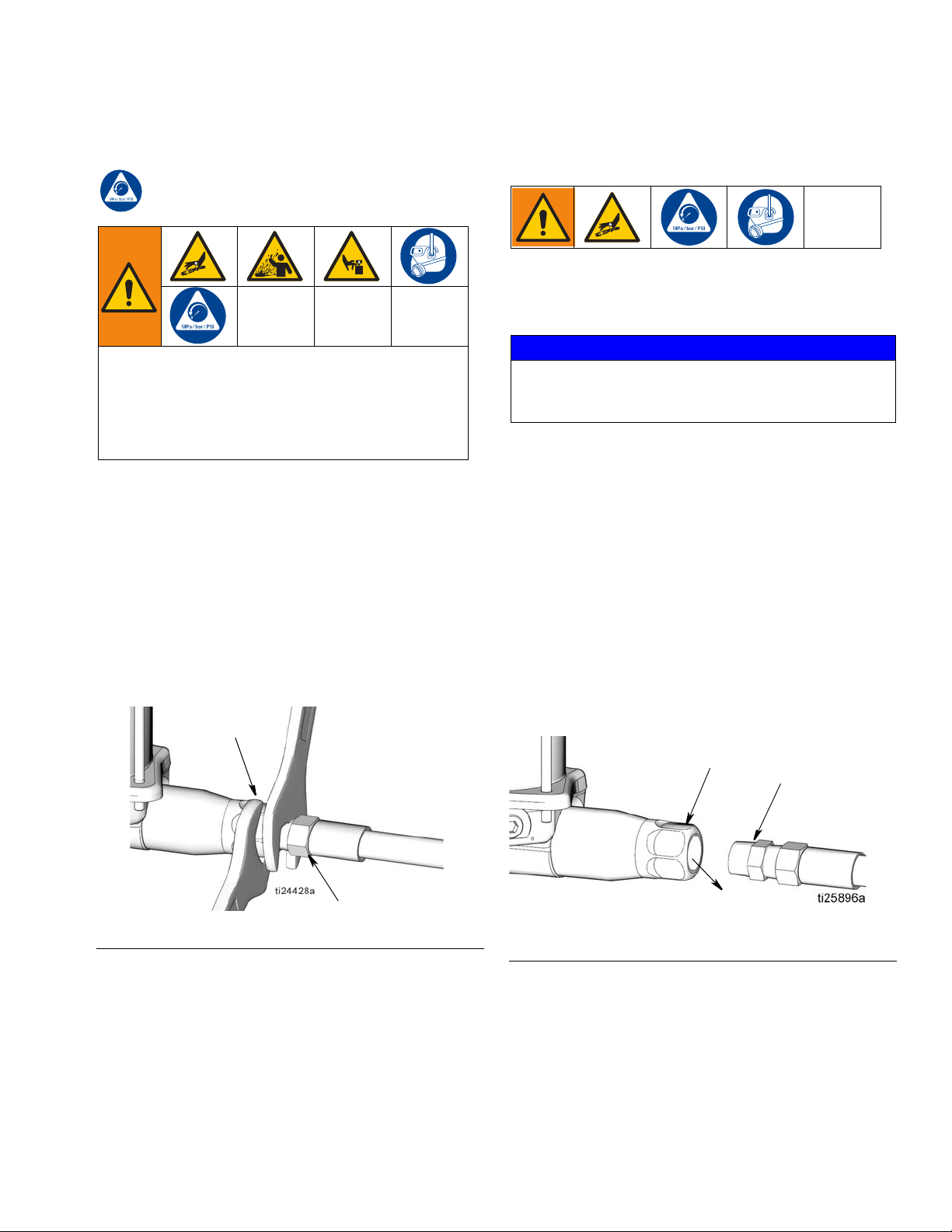
Pressure Relief Procedure
Follow the Pressure Relief Procedure whenever
you see this symbol.
This equipment stays pressurized until pressure is
manually relieved. To help prevent serious injury from
pressurized fluid, such as skin injection, splashing
fluid and moving parts, follow the Pressure Relief
Procedure when you stop dispensing and before
cleaning, checking, or servicing the equipment.
1. Close the bleed-type master air valve (F) (required
in the system).
2. Close the shut-off valve (V) on the oil input sup-
ply pump/system (DD).
3. Relieve pressure in system using two wrenches
working in opposite directions on the pump outlet
(E) and lubrication line fitting (G) to slowly
loosen the fitting until it is loose and no more lubri-
cant or air is leaking out of the fitting (F
IG. 7).
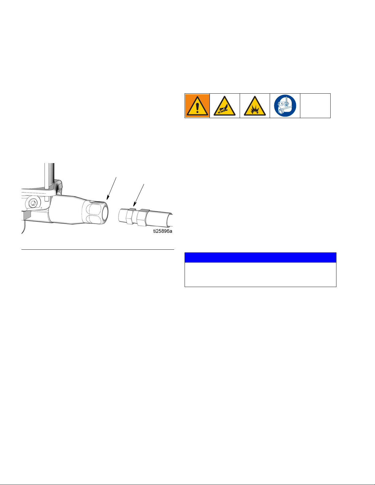
Air Lock Procedure
An air lock occurs when a bubble or pocket of air prevents the normal flow of the lubricant.
NOTICE
Running the pump dry will cause an air lock. To prevent
an air lock, do not run the pump without lubricant.
Always refill the pump before it is empty.
If there is an air lock, first:
• Check that input supply oil line (CC) is connected
and that the oil flow is continuous to reservoir (K).
• Loosen the cock valve (BB) from the pump reser-
voir cover (L) to bleed out the air.
If the air lock persists:
1. Relieve pressure. See Pressure Relief Procedure,
page 9.
2. Disconnect the lubricant supply line (G) from the
pump outlet (E) (F
IG. 8).
FIG. 7
3A3169E 9
FIG. 8
3. Open the bleed-type master air valve (F, page 4).
4. Open the shut-off valve (V).
Operation
E
G
5. Run the pump a few strokes until oil (ol), free of air,
comes out of the pump outlet (E) (F
• It may take up to 20 the pump strokes to expel the
air from the pump and deliver a continuous flow of
oil. This will depend on the viscosity of the lubricant
and temperature.
• Allow a minimum of 5 seconds ON time for the forward stroke and 5 seconds OFF time for the return
stroke.
6. Connect the pump outlet (E) to the lubrication line
(G) (F
IG. 9).
FIG. 9
IG. 8).
Operation
Start Up
1. Verify reservoir is filled with lubricant and system
has been Primed (see Prime System, page 8).
2. Turn on the lubrication controller (J) power switch.
3. Program the lubrication controller to actuate the
solenoid valve (C).
NOTE: See the lubrication controller instruction
manual included with the system for these instructions.
4. Open air regulators and master air valves.
NOTE: Never allow the pump to run dry of the material
being the pumped.
NOTICE
Running the pump dry will cause an air lock. To prevent
an air lock, do not run the pump without lubricant.
Always refill the pump before it is empty.
At the start of a the pump cycle:
a. The air solenoid (C) supplies air to the pump
air inlet (P).
b. On the pump forward stroke, lubricant is dis-
pensed to all the injectors.
c. The pump is supplied with air through the air
inlet (R).
d. The pump makes a return stroke, venting the
system pressure back to the pump and resetting
all of the injector.
10 3A3169E

Operation
llf
llf
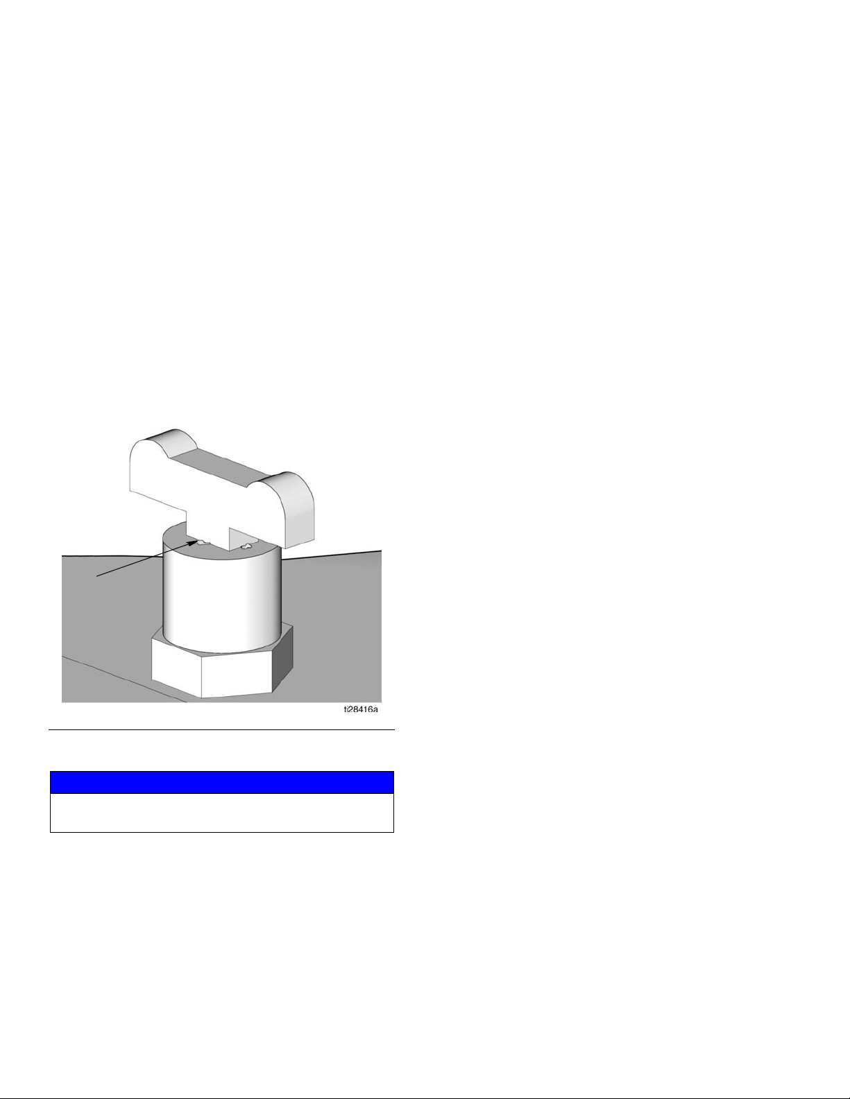
Low Level Switch
When the oil reservoir is full, the low level float (llf) sits in
the high, raised position as shown in F
FIG. 10: Low level float in raised position
As oil is dispensed, the low level float begins to travel
down. When the oil in the reservoir reaches low level,
the fully traveled down float (shown in F
the normally open low level switch and a low level signal
is sent to the lubricator controller (J).
IG. 10.
IG. 11) closes
Shut Down
To shut down the system:
a. Close the bleed-type master air valve (F).
b. Turn off electrical supply to the lubrication con-
troller (J).
c. Close the shut-off valve (V) on the oil input
supply pump/system (DD).
FIG. 11: Low level float in fully traveled down
position
To clear the low level fault/error:
• Check that input supply oil line (CC) is connected
and that the oil flow is continuous to reservoir (K).
• Loosen the cock valve (BB) from the pump reser-
voir cover (L) to bleed out the air.
FIG. 12
3A3169E 11

Operation
Lubrication System Sizing and Calculation Guidelines
Table 1: Lubricant Output and Pressure - US
NOTE: The lubricant output per pump stroke must be less than the amount of lubricant discharged per pump stroke.
1 2 3 4 5 6 7
Max
Injector
Typ e
Injector
Output
cu. in.
GL-43 0.008 0.016
GL42 0.003 0.006
Injector
Volu m e t o
Dispense
and Charge
cu. in.
Table 2: Lubricant Output and Pressure - Metric
1 2 3 4 5 6 7
Max
Injector
Type
Injector
Output
cc
GL-43 0.131 0.262
GL42 0.049 0.098
Injector
Volume to
Dispense
and Charge
cc
Max Pump
Lubricant
Maximum Pressure
Minimum
Pressure
Recommended Pressure
Output /
Stroke
cu. in.
3.0 1000 53 750 39 850 45
Max Pump
Lubricant
Output PSI
Maximum Pressure
Required Air
PSI
Output PSI
Minimum
Pressure
Required
Air PSI
Output PSI
Required Air
Recommended Pressure
Output /
Stroke
cc
49.1 6.9 (68.9) 0.36 (3.6) 5.2 (51.7) 0.26 (2.7) 5.9 (58.6) 0.31 (3.1)
Output
MPA (bar)
Required Air
MPA (bar)
Output
MPA (bar)
Required Air
MPA (bar)
Output
MPA (bar)
Required Air
PSI
MPA (bar)
1. Total Injector Volume to Dispense and Charge
a. Add together the total number of injectors in the sys-
tem.
b. From Table 1 or Table 2 above, find your Injector Type
in the first column and the related Injector Volume to
Charge in the third column. Multiply this value by the
total number of injectors determined in Step a
(above).
2. Calculate the volume of lubricant in the Pipeline (G):
a. Use the pipe’s inside diameter (ID) measurement to
calculate the area of the pipe.
b. Measure the length of the pipe (G) only. Do not
include the feeder lines (S) in this calculation.
c. Multiply the area of the pipe (calculated in Step a) by
the length of the pipe (measured in Step b).
3. Calculate line expansion and fluid compression in the pipe
using the 10% Rule.
a. Multiply the volume calculated in Step 2 by 10%.
4. Calculate the Total System Volume required.
a. Add together the total from Step 1 and Step 3 ONLY.
Do NOT include Step 2.
b. The Total System Volume required must be less than
the Pump Lubricant Output / Stroke provided in the
fourth column of Table 1 or Table 2.
c. If the Total System Volume required is greater than
the Pump Lubricant Output / Stroke provided in the
fourth column of Table 1 or Table 2, split the system
into two or more systems.
12 3A3169E

Repair
Repair
Seal Replacement
NOTE: For most seal replacement procedures, the
pump should be completely removed from service and
clamped in a vise. If you are only replacing the reservoir
and/or reservoir seals, you do not have to remove the
pump from it’s service location. The following instructions cover the complete disassembly of the pump. Your
pump repair may not require total pump disassembly.
Disassembly
1. Turn off air supply and disconnect air lines to the
pump.
2. Disconnect electrical connections to lubrication controller.
3. Close shut-off valve (V) to turn off oil input supply
pump/system (DD).
4. Relieve pressure (page 9).
7. Remove mounting bolts (F
pump from service.
FIG. 14
8. Clamp the pump base in a vise as shown in F
Use a soft-jaw vise or place a rag in the vise jaws to
protect the surface of the pump base.
IG. 14) and remove the
IG. 15.
5. Disconnect supply line (G) from the pump outlet
(E).
6. Slowly loosen and remove oil input line from the
pump base and drain oil from the pump (F
NOTE: Removing the oil input line slowly will help
prevent splashing while the oil drains from the reservoir.
FIG. 13
IG. 13).
FIG. 15
9. Collect drained oil in a pail or waste container. Dispose of oil according to all regulations for proper disposal.
3A3169E 13

Repair
29
27
30
27
1
26
26
30
2
3
4
3
10. Use a wrench to remove tie rods (29). Loosen the
rods in a diagonal pattern, taking care to loosen
each rod gradually until all rods are completely loosened. Remove tie rods (29). See F
IG. 16.
FIG. 16
11. Remove cover (30) from reservoir (27) (F
IG. 16).
12. Remove reservoir (27) from the pump base (1) (F
17). If replacing reservoir o-rings (26), remove
o-rings from reservoir and cover. Dispose of o-rings
according to all regulations for proper disposal.
IG.
13. Remove piston stop nut (3) from top of the air cylinder (2) (F
IG. 18).
FIG. 18
14. Remove o-ring (4) from piston stop nut (3). Dispose
of o-ring according to all regulations for proper disposal.
FIG. 17
FIG. 19
14 3A3169E

Repair
33
2
1
33
13
6
2
13
5
6
41
13
15. Use a 3/8 inch socket to remove the 4 bolts (33)
holding the air cylinder (2) to the pump base (1)
(F
IG. 20). Remove air cylinder from the pump base.
FIG. 20
16. Piston Rod (13) and Piston (6)
a. Pull piston rod (13) and piston (6) out of air cyl-
inder (2) (F
IG. 22).
face of the piston and cause fluid leaks during
the pump operation. Only move the wrench
holding the nut (5) to loosen and remove the
nut.
FIG. 22
c. Remove o-ring (41) from the piston rod (13)
(F
IG. 23).
FIG. 23
FIG. 21
b. To separate piston rod (13) and piston (6) use
two wrenches, working in opposite directions.
Secure one open end wrench to flats of piston
rod and the second wrench is used to loosen
the nut (5) as shown in F
IG. 22.
NOTE: The open end wrench secured to the
flats of the piston rod is only used to hold the
rod securely, do not rotate this wrench. Moving
this wrench could scratch or damage the sur-
3A3169E 15

Repair
6
7
4
15
1
d. Remove o-ring (7) from piston (6) (FIG. 24).
FIG. 26
FIG. 24
e. Discard o-rings (7, 41) and nut (5) according to
all regulations for proper disposal
17. Remove the outlet check valve (15) from the pump
base (1) (F
IG. 25). Remove o-ring (4) from outlet
check valve. Dispose of o-ring according to all regulations for proper disposal.
FIG. 25
19. Throat Seal Kit
The Throat Seal Kit includes the following parts
(F
IG. 27):
• Retaining Ring (9)
• Tapered Spacer (10)
•Seal (11)
• Spacer (12)
• Retaining Ring (51)
• Spacer (12)
•Seal (11)
• Spacer (12)
18. Reposition the pump base (1) in the vise as shown
in F
IG. 26.
16 3A3169E

Repair
9
10
(install tapered side down)
11
(install lips up)
12
51
12
11
12
51*
(install lips down)
(do not remove from pump)
9
(te)
(ha)
53
(br)
c. Use the blade of a small, flat screw driver under
the tapered edge (fe) of retaining ring (51) to
remove the ring as shown in F
IG. 28 and remove
the retaining ring.
d. Remove spacer (12), seal (11), and spacer (12).
DO NOT REMOVE THE LAST RETAINING
RING (51).
e. Dispose of all parts according to all regulations
for proper disposal.
20. Use a soft brass rod (br) and hammer to gently tap
the pump element sleeve (53) out of the pump base
IG. 29).
(1) (F
Use your hand to catch the sleeve while tapping it
out of the pump base to make sure it does not drop
on the ground or table which could damage the
sleeve.
FIG. 27
*This part is shown for reference only. It is not included
in the Throat Seal Kit.
a. Slide the blade of a small, flat screw driver
under the tapered edge (te) of retaining ring (9)
and remove the ring as shown in F
IG. 28.
FIG. 29
NOTE: Be careful not to scratch or damage the sleeve
and/or the pump base housing (1) when tapping the
FIG. 28
b. Remove the tapered spacer (10), seal (11), and
spacer (12).
sleeve out of the pump base or when removing the
o-ring. A scratched or damaged sleeve and or pump
base housing (1) will result in fluid leaking during the
pump operation and will prevent the pump from operating correctly.
3A3169E 17

Repair
14
53
8
1
21. Remove o-ring (14). Dispose of o-ring according to
all regulations for proper disposal.
Reassembly
NOTE: Always use all new parts included in replace-
ment kits. Discard used parts according to all applicable
regulations for proper disposal.
1. Use a clean cloth to wipe down the pump base (1)
and remove any dirt or contaminants. Inspect surface for any scratches or damage. Replace the
pump if the pump base is damaged.
2. If necessary, reposition the pump base (1) in the
vise as shown in F
IG. 32.
FIG. 30
22. Remove square o-ring (8) from the pump base (1)
(F
IG. 31). Dispose of o-ring according to all regula-
tions for proper disposal
FIG. 31
FIG. 32
3. Throat Seal Installation
The Throat Seal Kit includes the following parts
(F
IG. 33):
• Retaining Ring (9)
• Tapered Spacer (10)
•Seal (11)
• Spacer (12)
• Retaining Ring (51)
• Spacer (12)
•Seal (11)
• Spacer (12)
18 3A3169E

Repair
9
10
(install tapered side down)
11
(install lips up)
12
51
12
11
12
51*
(install lips down)
(do not remove from pump)
12
(bb)
11
12
d. Install seal (11). Be sure the lips of the seal are
facing down as shown in F
IG. 35.
NOTE: Make sure the seal lip is not damaged
while pressing the seal through the clip grooves.
FIG. 35
FIG. 33
e. Install spacer (12) (F
IG. 36).
*This part is shown for reference only. It is not included
in the Throat Seal Kit.
a. Apply a thin layer of grease to all the seals
included in the kit and the pump base bore (bb).
b. Verify retaining ring (51) is in place in side the
pump base (1).
c. Install spacer (12) shown in F
IG. 34.
FIG. 36
FIG. 34
3A3169E 19

Repair
51
12
11
10
f. Install retaining clip (51) (FIG. 37). You should
hear a “click” when the retaining clip is correctly
seated in the groove.
FIG. 37
g. Install spacer (12) (F
IG. 38).
h. Install seal (11), with the lips facing up as shown
in F
IG. 39.
NOTE: Make sure the seal lip is not damaged
while pressing the seal through the clip grooves.
FIG. 39
i. Install the tapered spacer (10), tapered side fac-
ing down as shown in F
IG. 40.
FIG. 38
FIG. 40
20 3A3169E

Repair
9
53
14
j. Install clip (9) (FIG. 41). You should hear a “click”
when the retaining clip is correctly seated in the
groove.
FIG. 41
4. Reposition the pump base (1) in the vise as shown
in F
IG. 42.
5. Pump Element Sleeve (53)
a. Use a clean cloth to wipe down the pump ele-
ment sleeve (53) and remove any dirt or contaminants. Inspect surface for any scratches or
damage.
b. Apply a thin layer of grease to o-ring (14). Install
o-ring around the pump element sleeve (d) (F
43).
IG.
FIG. 42
FIG. 43
c. Install the pump element sleeve (53) in the
pump base (1). To determine the correct installation orientation, refer to F
IG. 44.
NOTE: When the sleeve is installed in the pump
base correctly, the notches (n) around the bottom of the sleeve will go into the pump base first
and the o-ring will be on the top.
3A3169E 21

Repair
53
1
(n)
53
1
4
15
FIG. 44
d. Use your thumbs to press the sleeve (53) into
the pump base (1). Then using a soft rod, press
the sleeve all the way down as far as possible
(F
IG. 45).
6. Outlet Check Valve (15)
a. Use a clean cloth to wipe down the outlet check
valve (15) and remove any dirt or contaminants.
Inspect surface for any scratches or damage.
Replace damaged parts.
NOTE: The outlet check valve consists of a ball
check inside the bore. It is not repairable. If
there is any damage or contamination in the
bore, replace the check valve.
b. Apply a thin layer of grease to o-ring (4). Install
o-ring around the outlet check valve (15) (F
46).
IG.
FIG. 45
NOTE: Be careful not to scratch or damage the
sleeve and/or the pump base housing (1) when
installing the sleeve in the pump base.
Scratched or damaged surfaces will create a
path for the fluid to leak during the pump operation and will prevent the pump from operating
correctly.
FIG. 46
c. Thread the outlet check valve (15) into the
pump base (1) (F
IG. 47). Tighten securely. Then
torque to 50 to 55 ft. lbs (67.8 to 74.5 N•m).
22 3A3169E

FIG. 47
15
1
8
1
13
41
6
13
7. Apply a thin layer of grease to square o-ring (8).
Install square o-ring (8) in groove in the pump base
(1) as shown in F
IG. 48.
8. Piston Rod (13) and Piston (6)
NOTE: Do not clamp piston rod (13) in vise.
a. Use a clean cloth to wipe down the piston rod
(13) and piston (6) and remove any dirt or contaminants. Inspect surfaces for any scratches or
damage. Replace damaged parts.
b. Apply a thin layer of grease to o-ring (41). Install
o-ring over the grooves of the piston rod (13)
(F
IG. 49).
NOTE: If needed, a pick can be used to help
seat the o-ring over the grooves of the piston
rod (13).
Repair
FIG. 49
c. Push piston (6) over end of piston rod (13) until
it is seated on the rod (F
IG. 50).
NOTE: You should hear a pop sound when it is
in place correctly.
FIG. 48
FIG. 50
3A3169E 23

Repair
13
6
5
7
6
13
1
2
6
1
d. Install nut (5) over the end of the piston rod (13).
Use two wrenches, working in opposite directions to tighten the nut. Secure one open end
wrench to flats of piston rod and use the second
wrench to tighten the nut (5) as shown in F
IG.
51.
NOTE: The open end wrench secured to the
flats of the piston rod is only used to hold the
rod securely, do not rotate this wrench. Moving
this wrench could scratch or damage the surface of the piston and cause fluid leaks during
the pump operation. Only move the wrench
holding the nut (5) to tighten the nut. Torque nut
to 15 to 17 ft. lbs (20.3 to 23.1 N•m).
f. Apply a thin layer of grease around and along
the entire length of the piston rod (13). Gently
push the piston rod into the pump base (1)
using a push and turn motion to work the rod
through the previously installed, seals and spacers (F
IG. 53).
FIG. 53
9. Air Cylinder
FIG. 51
e. Apply a thin layer of grease to o-ring (7). Install
o-ring (7) around piston (6) as shown in F
IG. 52.
a. Use a clean cloth to wipe inside the air cylinder
(2) and remove any dirt or contaminants.
b. Apply a thin layer of grease to the inside sur-
faces of the air cylinder (2). Slide the air cylinder
(2) over the piston (6) and push it all the way
down until it is seated tightly to the pump base
(1). See F
IG. 54.
Make sure the Graco G in the air cylinder is facing out.
FIG. 54
FIG. 52
24 3A3169E

Repair
33
4
3
2
3
26
1
27
GL
c. Install 4 new bolts. Hand tighten the bolts (33)
evenly, each one a little at a time in a diagonal
pattern. Then torque diagonally to 10-13 ft. lbs.
(13.5-17.6 N•m). See F
IG. 55.
FIG. 55
d. Apply a thin layer of grease to o-ring (4). Install
o-ring to piston stop nut (3) (F
IG. 56).
e. Thread piston stop nut (3) into top of air cylinder
(2) as shown in F
IG. 57. Wrench tighten nut.
Then torque nut to 15 to 17 ft. lbs (20.3 to 23.1
N•m).
FIG. 56
FIG. 57
10. Apply a thing layer of grease to o-ring (26). Install
o-ring (26) into groove in the pump base (1) as
shown in F
IG. 58.
NOTE: This is the only correct way to install this
o-ring and ensure it will not slip out of place when
the reservoir is installed over the pump base.
3A3169E 25
FIG. 58

Repair
30
26
30
27
26
29
30
11. Install reservoir (27) into the pump base (1) with
Graco Identification label (GL) facing to the front of
the pump base as shown in F
IG. 58. Take care to not
pinch or move the o-ring.
12. Apply a thin layer of grease to o-ring (26). Install
o-ring inside groove in cover (30) as shown in (F
59).
NOTE: This is the only correct way to install this
o-ring and ensure it will not slip out of place when
the cover is installed on the reservoir.
14. Install tie rods (29) Evenly tighten tie rods in a diagonal pattern, a little at a time. Torque to 12-13 in.
lbs. (1.4 - 1.5 N•m). Take care not to over tighten
any of the rods.
IG.
FIG. 61
15. Reinstall the pump in the service location. See
Installation Instructions beginning on page 4.
FIG. 59
13. Position cover (30) over reservoir (27). Take care to
not pinch or move the o-ring (F
IG. 60).
FIG. 60
26 3A3169E

Troubleshooting
Problem Cause Solution
The pump is not operating. No lubricant
flow.
Injectors not cycling or only some of the
injectors are operating
Troubleshooting
No air 1. Adjust air pressure/supply.
2. Open bleed-type master air valve
(F) (page 4).
No lubricant in reservoir Check oil input supply system.
Losing prime
Remove trapped air (see Air Lock,
page 9).
No lubricant flow See Pump is not operating. No lubricant
flow in Troubleshooting table.
Low pressure or no pressure 1. Check piping for leaks. If a leak is
detected, repair or replace piping.
Pump seals are bad
2. Check injectors for leaks. If a leak is
detected, repair or replace injector.
3. If the total system volume is greater
than the Pump Lubricant Output provided in Table 1 or Table 2, split the
system into two or more systems.
Refer to Lubrication System Sizing
and Calculation Guidelines, page 28.
Replace seals. See Parts, page 29.
3A3169E 27

Parts
29
30
26
42
27
52
26
19
37
15
14
1
36
51
12
10
8
11
9
13
6
7
5
2
41
4
3
4
53
33
39
51
11
38
54
31
Parts
28 3A3169E

Parts
Parts
Ref Part No. Description Qty
1 PUMP BASE 1
2 160613 CYLINDER, air 1
3 NUT, piston stop 1
4
5
6PISTON, air 1
7
8
9
10
11
12
13 PISTON 1
14
15 17D305 VALVE, dual outlet check 1
19
26
27 RESERVOIR 1
29 ROD, tie, reservoir 3
30 COVER 1
156698
104095
PACKING, o-ring 2
NUT, hex, lock, nylon, thin 1
PACKING, o-ring 1
PACKING, square 1
RING, retaining internal 1
SPACER, seal. wedge 1
SEAL, oil 2
SPACER, seal 3
PACKING, o-ring 1
FLOAT, low level (model, 24Y499,
25Y499)
O-RING, reservoir 2
Ref Part No. Description Qty
31 VALVE, air cock, 1/4” NPT 1
33 101578 SCREW, cap, hex, hd 4
36
37 NUT, low level float mount 1
38 PACKING, o-ring 1
39
41 PACKING, o-ring 1
128434 LABEL, safety, warning 1
42
51 RING, snap 2
52 128433 LABEL, branding 1
53 SLEEVE, pump element 1
128625 LABEL, pressure rating 1
54
Replacement Danger and Warning labels, tags and cards
1
are available at no cost.
Included in Seal Replacement Kit 24X889.
NOTE: Only one (#51) is included in the kit.
SENSOR, low level with float (models
24Y499, 25Y499)
PLUG (models 24Y498, 25Y498) 1
CONNECTOR, DIN, Form A, 4-pin
(models 24Y499, 25Y499)
1
1
3A3169E 29

Dimensions and Mounting
Dimensions and Mounting
30 3A3169E

Technical Data
H1900 Single Stroke Pump, Oil
US Metric
Maximum fluid working pressure 3500 psi 24 MPa, 241 bar
Pressure ratio19:1 19:1
Pump output 3.0 cu. inch/stroke
Oil input supply pressure 80 psi 0.55 MPa, 5.5 bar
Maximum air inlet pressure 185 psi 1.27 MPa, 12.76 bar
Air inlet size 1/4 in. NPT
Fluid outlet size 3/4 in. NPT‡
Oil input supply size 3/8 in. NPT
Pump: high phosphorus electroless nickel plated dectile iron,
enamel painted dectile aluminum, zinc nickel coated steel, acetal
Wetted Parts
Approximate weight 22 lbs 9.9 kg
Operating temperature 14°F to 149°F -10°C to 65°C
Low Level
Switch Rating 30 Volts; 0.3 Amps
IP ratings IP65 when plugged and screwed down
Cable diameter 0.315 to 0.394 inches 8 to 10 mm
Wire size 20 to 16 AWG
plastic, 6061 aluminum alloy, enamel painted aluminum alloy 308,
aluminum alloy 308
Seals: Buna-N (nitrile)
120 Volts; 0.13 Amps
240 Volts; 0.06 Amps
0.5 to 1.5 mm
2
Technical Data
Models 25Y498 and 25Y499 are supplied with three, 1/4 in. NPT(m) x 1/4 in. BSPP(f) fittings as loose items. Two are supplied
for the air inlet and one for the pump outlet.
Models 25Y498 and 25Y499 are supplied with one, 3/8 in. NPT(m) x 3/8 in. BSPP(f) fitting as a loose item.
‡ All the pumps are supplied with 3/4 in. NPT(m) x 1/4 inch NPT(f) reducers if needed.
3A3169E 31

Graco Standard Warranty
Graco warrants all equipment referenced in this document which is manufactured by Graco and bearing its name to be free from defects in
material and workmanship on the date of sale to the original purchaser for use. With the exception of any special, extended, or limited warranty
published by Graco, Graco will, for a period of twelve months from the date of sale, repair or replace any part of the equipment determined by
Graco to be defective. This warranty applies only when the equipment is installed, operated and maintained in accordance with Graco’s written
recommendations.
This warranty does not cover, and Graco shall not be liable for general wear and tear, or any malfunction, damage or wear caused by faulty
installation, misapplication, abrasion, corrosion, inadequate or improper maintenance, negligence, accident, tampering, or substitution of
non-Graco component parts. Nor shall Graco be liable for malfunction, damage or wear caused by the incompatibility of Graco equipment with
structures, accessories, equipment or materials not supplied by Graco, or the improper design, manufacture, installation, operation or
maintenance of structures, accessories, equipment or materials not supplied by Graco.
This warranty is conditioned upon the prepaid return of the equipment claimed to be defective to an authorized Graco distributor for verification of
the claimed defect. If the claimed defect is verified, Graco will repair or replace free of charge any defective parts. The equipment will be returned
to the original purchaser transportation prepaid. If inspection of the equipment does not disclose any defect in material or workmanship, repairs will
be made at a reasonable charge, which charges may include the costs of parts, labor, and transportation.
THIS WARRANTY IS EXCLUSIVE, AND IS IN LIEU OF ANY OTHER WARRANTIES, EXPRESS OR IMPLIED, INCLUDING BUT NOT LIMITED
TO WARRANTY OF MERCHANTABILITY OR WARRANTY OF FITNESS FOR A PARTICULAR PURPOSE.
Graco’s sole obligation and buyer’s sole remedy for any breach of warranty shall be as set forth above. The buyer agrees that no other remedy
(including, but not limited to, incidental or consequential damages for lost profits, lost sales, injury to person or property, or any other incidental or
consequential loss) shall be available. Any action for breach of warranty must be brought within two (2) years of the date of sale.
GRACO MAKES NO WARRANTY, AND DISCLAIMS ALL IMPLIED WARRANTIES OF MERCHANTABILITY AND FITNESS FOR A
PARTICULAR PURPOSE, IN CONNECTION WITH ACCESSORIES, EQUIPMENT, MATERIALS OR COMPONENTS SOLD BUT NOT
MANUFACTURED BY GRACO. These items sold, but not manufactured by Graco (such as electric motors, switches, hose, etc.), are subject to
the warranty, if any, of their manufacturer. Graco will provide purchaser with reasonable assistance in making any claim for breach of these
warranties.
In no event will Graco be liable for indirect, incidental, special or consequential damages resulting from Graco supplying equipment hereunder, or
the furnishing, performance, or use of any products or other goods sold hereto, whether due to a breach of contract, breach of warranty, the
negligence of Graco, or otherwise.
FOR GRACO CANADA CUSTOMERS
The Parties acknowledge that they have required that the present document, as well as all documents, notices and legal proceedings entered into,
given or instituted pursuant hereto or relating directly or indirectly hereto, be drawn up in English. Les parties reconnaissent avoir convenu que la
rédaction du présente document sera en Anglais, ainsi que tous documents, avis et procédures judiciaires exécutés, donnés ou intentés, à la suite
de ou en rapport, directement ou indirectement, avec les procédures concernées.
Graco Information
For the latest information about Graco products, visit www.graco.com.
For patent information, see www.graco.com/patents.
TO PLACE AN ORDER, contact your Graco distributor or call to identify the nearest distributor.
Phone: 612-623-6928 or Toll Free: 1-800-533-9655, Fax: 612-378-3590
All written and visual data contained in this document reflects the latest product information available at the time of publication.
GRACO INC. AND SUBSIDIARIES • P.O. BOX 1441 • MINNEAPOLIS MN 55440-1441 • USA
Copyright 2015, Graco Inc. All Graco manufacturing locations are registered to ISO 9001.
Graco reserves the right to make changes at any time without notice.
Original instructions. This manual contains English. MM 3A169
Graco Headquarters: Minneapolis
International Offices: Belgium, China, Japan, Korea
www.graco.com
Revised
March 2017
 Loading...