

Graco LubePro H1900, LubePro 24Y498, LubePro 24Y499, LubePro 25Y499, LubePro 25Y498 Instructions Manual
Instructions
™
H1900 LubePro
3A3169E
Oil Pump
For pumping non-corrosive and non-abrasive lubricants only. For professional use only.
Not approved for use in explosive atmospheres or hazardous locations.
Model No.
24Y498 - 19:1 Oil pump without Low Level
24Y499 - 19:1 Oil pump with Low Level
25Y498- 19:1 Oil pump without Low Level, includes BSPP adapter
25Y499 - 19:1 Oil pump with Low Level, includes BSPP adapter
EN
80 psi (0.55 MPa, 5.5 bar) Maximum Oil Input Pressure
3500 psi (24 MPa, 241 bar) Maximum Working Pressure
Important Safety Instructions
Read all warnings and instructions in this manual.
Save these instructions.
Warnings
WARNING
WARNINGWARNING
Warnings
The following warnings are for the setup, use, grounding, maintenance, and repair of this equipment. The exclamation point symbol alerts you to a general warning and the hazard symbols refer to procedure-specific risks. When
these symbols appear in the body of this manual or on warning labels, refer back to these Warnings. Product-specific
hazard symbols and warnings not covered in this section may appear throughout the body of this manual where
applicable.
PRESSURIZED EQUIPMENT HAZARD
Over-pressurization can result in equipment rupture and serious injury.
• Do not exceed the maximum oil inlet pressure.
• Do not exceed the maximum air input pressure.
• Use tubing, hoses and other components with pressure ratings equal to or higher than the pump
rating.
SKIN INJECTION HAZARD
High-pressure fluid from dispensing device, hose leaks or ruptured components will pierce skin. This
may look like just a cut, but it is a serious injury that can result in amputation. Get immediate surgi-
cal treatment.
• Do not point dispensing device at anyone or at any part of the body
• Do not put your hand over the fluid outlet.
• Do not stop or deflect leaks with your hand, body, glove, or rag.
• Follow the Pressure Relief Procedure when you stop dispensing and before cleaning, checking,
or servicing equipment.
• Tighten all fluid connections before operating the equipment.
• Check hoses and couplings daily. Replace worn or damaged parts immediately.
EQUIPMENT MISUSE HAZARD
Misuse can cause death or serious injury.
• Do not operate the unit when fatigued or under the influence of drugs or alcohol.
• Do not exceed the maximum working pressure or temperature rating of the lowest rated system
component. See Technical Data in all equipment manuals.
• Use fluids and solvents that are compatible with equipment wetted parts. See Technical Data in
all equipment manuals. Read fluid and solvent manufacturer’s warnings. For complete information
about your material, request Safety Data Sheet (SDS) from distributor or retailer.
• Turn off all equipment and follow the Pressure Relief Procedure when equipment is not in use.
• Check equipment daily. Repair or replace worn or damaged parts immediately with genuine manufacturer’s replacement parts only.
• Do not alter or modify equipment. Alterations or modifications may void agency approvals and create safety hazards.
• Make sure all equipment is rated and approved for the environment in which you are using it.
• Use equipment only for its intended purpose. Call your distributor for information.
• Route hoses and cables away from traffic areas, sharp edges, moving parts, and hot surfaces.
• Do not kink or over bend hoses or use hoses to pull equipment.
• Keep children and animals away from work area.
• Comply with all applicable safety regulations.
2 3A3169E
Warnings
WARNING
WARNINGWARNING
MOVING PARTS HAZARD
Moving parts can pinch, cut or amputate fingers and other body parts.
• Keep clear of moving parts.
• Do not operate equipment with protective guards or covers removed.
• Pressurized equipment can start without warning. Before checking, moving, or servicing equipment, follow the Pressure Relief Procedure and disconnect all power sources.
TOXIC FLUID OR FUMES HAZARD
Toxic fluids or fumes can cause serious injury or death if splashed in the eyes or on skin, inhaled, or
swallowed.
• Read Safety Data Sheet (SDS) to know the specific hazards of the fluids you are using.
• Store hazardous fluid in approved containers, and dispose of it according to applicable guidelines.
PERSONAL PROTECTIVE EQUIPMENT
Wear appropriate protective equipment when in the work area to help prevent serious injury, including eye injury, hearing loss, inhalation of toxic fumes, and burns. Protective equipment includes but is
not limited to:
• Protective eyewear, and hearing protection.
• Respirators, protective clothing, and gloves as recommended by the fluid and solvent manufacturer.
3A3169E 3
Installation
J
B2
B1
F
B3
C
D
H
K
G
L
A
M
E
N
R
P
S
T
W
U
AA
V
Y
CC
EE
DD
UU
UU
UU
BB
Installation
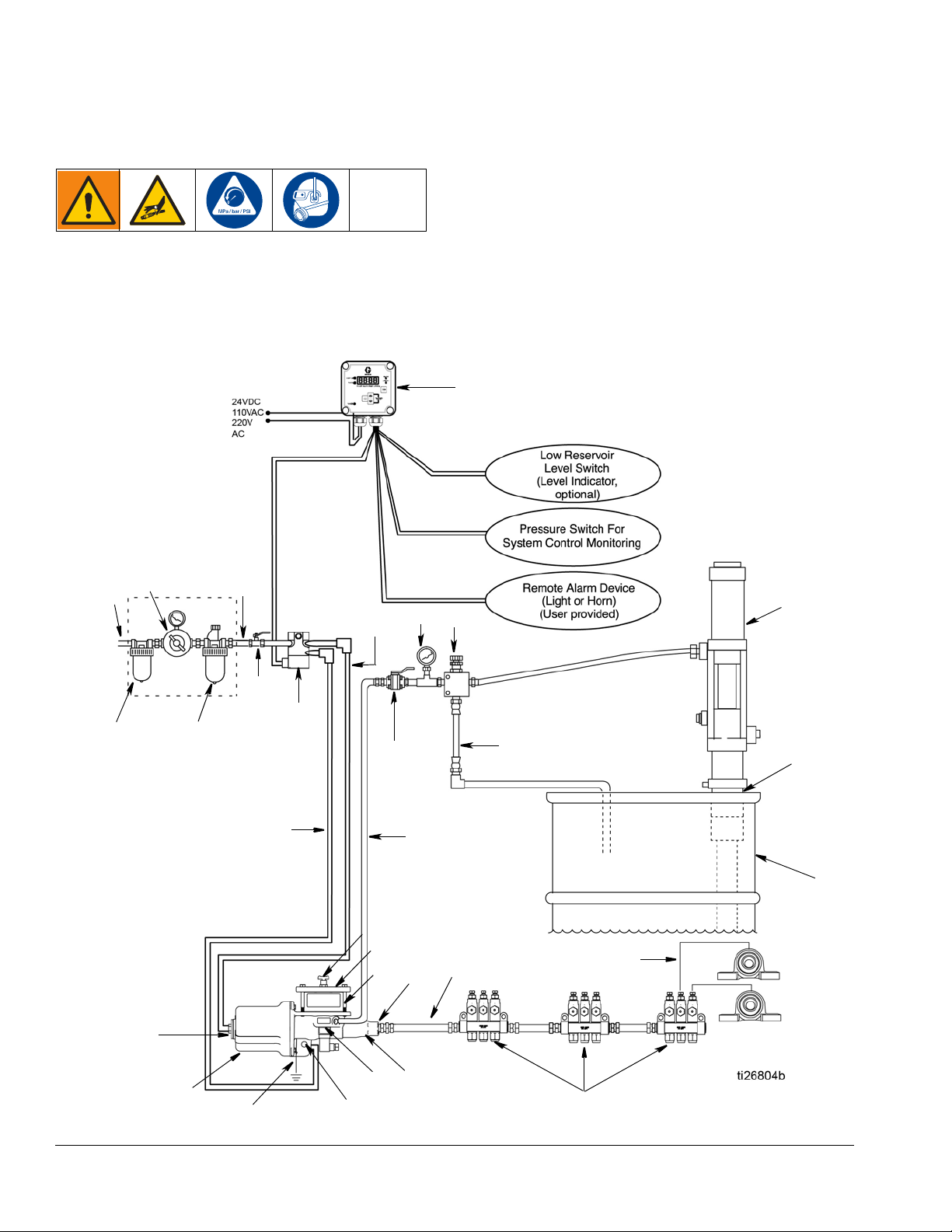
Typical Installation
Throughout this manual, reference letters used in the instructions, refer to the reference letters used in the Typical
Installation illustration shown in F
IG. 1.
FIG. 1: Typical Installation
4 3A3169E
Installation
RT
GW
GS
Typical Installation Key:
A Main air supply
B Filter/Regulator/Lubricator Assembly
B1 - Air Filter
B2 - Air Regulator
B3 - Air Lubricator
C Air solenoid valve (4-way)
D Pump module
E Pump outlet
F Bleed-type master air valve (required)
G High pressure lubricant supply lines (user supplied)
HInjector
J Lubricator controller
K Pump reservoir
L Pump reservoir cover
M Ground
N Pump outlet check body
P Pump air inlet - forward stroke
R Pump air inlet - return stroke
S Feeder lines
TLow level
U Pressure reducing valve (required in systems over 80 psi
(0.55 MPa, 5.5 bar)
V Supply line shut-off valve (required)
WDrum
Y Pressure gauge
AA Bung adapter
BB Cock valve
CC Oil input supply line
DD Oil input supply pump/system
EE Drain hose
UU Air supply lines
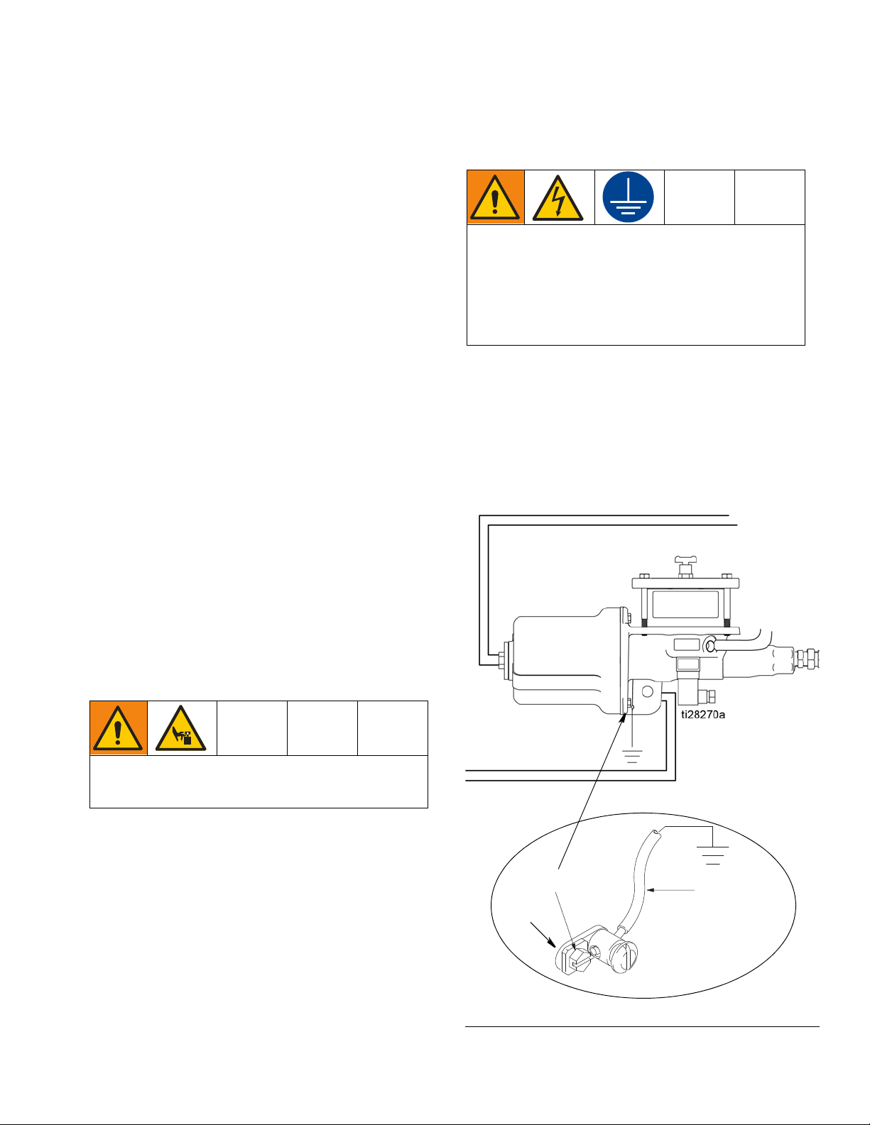
Grounding
Grounding is necessary when voltages above 30
VAC or 42 VDC are used for the low level switch or
for an air valve attached to the pump. Improper
grounding can cause electric shock. Grounding
reduces the risk of electric shock by providing an
escape wire for the electric current in the event of
malfunction or breakdown.
To ground the pump: Remove the ground screw (GS)
located on the back of the pump base and insert it
through the eye of the ring terminal (RT) at end of
ground wire (GW). Fasten the ground screw (GS) back
onto the pump and tighten securely. Connect the other
end of the ground wire to a true earth ground. See F
2.
IG.
Mounting
Mount pump securely so it cannot move around
during operation. Failure to do so could result in personal injury and/or equipment damage.
Install the pump in a location that will adequately support the weight of pump when filled with lubricant and
also provides easy operator access to the pump air controls. Pump must be mounted in a vertical position with
the reservoir up.
See Technical Data, page 31 for pump weight information and the Dimensions and Mounting layout, page 30.
3A3169E 5
FIG. 2
Installation
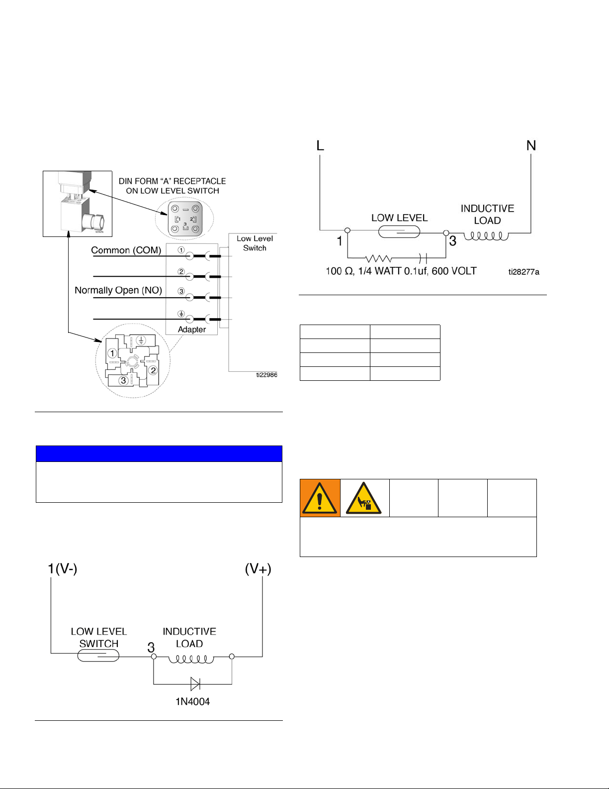
Low Level Models Only
DIN Connector
Connection is made to PINS 1 and 3 of the DIN Field
Wireable Connector. See F
page 31 for electrical ratings.
IG. 3. See Technical Data,
AC Voltage - A resistor and capacitor (high impedance
60 hertz) connected in parallel with the switch, as shown
in F
IG. 5, is recommended.
FIG. 5
Switch Ratings
Volts Amps
30 0.3
120 0.13
240 0.06
FIG. 3
Recommended Protection
NOTICE
Connecting the low level switch directly to the load
may weld the contacts or erode the contact surface,
resulting in a shorter switch life.
DC Voltage - A 1N4004 diode (or equivalent) connected
cathode-to-positive, shown in F
IG. 4, is recommended.
Air and Fluid Line Accessories
Install the air line accessories in the order shown in FIG.
1, page 4.
Trapped air can cause the pump to cycle unexpectedly, which could result in serious injury from splashing or moving parts.
Bleed-type master air valve (F): required in your system to relieve air trapped between it and the pump.
Air line filter (B1): removes harmful dirt and moisture
from compressed air supply.
Pump air regulator (B2): to control pump speed and
outlet pressure. Locate it close to the pump.
FIG. 4
6 3A3169E
Installation
NOTICE
Do not mount the air accessories directly on the solenoid valve air inlet. The air inlet and fittings are not
strong enough to support the accessories and may
break. Provide a bracket on which to mount the
accessories.
1. Install a bleed-type master air valve (F) to relieve
air trapped between it and the pump. Install the
valve in a location that is easily accessible from the
pump and located downstream of the air regulator.
2. Install an air line filter (B1) to remove harmful dirt
and contaminants from the compressed air supply
3. Install the air regulator (B2) to control pressure.
4. Install an air line lubricator (B3) to lubricate the air
cylinder.
5. Install the (4-way) air solenoid valve (C) for control
of the pump forward and return strokes.
The maximum working pressure of each component
in the system may not be the same. To reduce the
risk of over-pressurizing any part of your system,
know the maximum working pressure rating of each
component and its connected components. Never
exceed the maximum working pressure of the lowest
rated components connected to a particular pump.
Oil Input Supply System
To reduce the risk of over-pressurizing the LubePro
Single Stroke Pump which could cause a rupture and
serious injury, including fluid injection, an oil input
supply system must have a means to limit the incoming fluid pressure to the LubePro Single Stroke Pump
to a maximum of 80 psi (0.55 MPa, 5.5 bar).
The oil input supply pump/system (DD) must have a
pressure reducing valve (U).
Oil Input Lines
Shut-off Valve (V): Allows isolation of the LubePro
pump from the incoming oil supply line (CC).
Required on the oil input supply pump/system (DD).
Hoses: Use a minimum 3/8 inch supply line (S).
Pressure Reducing Valve (U): circulates excess oil
pressure back to the tank. Install this valve (U) in the
supply line with a drain hose (EE). Limit supply pressure to a maximum 80 psi (0.55 MPa, 5.5 bar)).
Fluid-filled Pressure Gauge (Y): monitors hydraulic
pressure to the LubePro Single Stroke Pump during
startup.
To use the air regulator reading to determine the fluid
output pressure, multiply the ratio of the pump (19:1) by
the air pressure shown on the regulator gauge or see
Table 1: Lubricant Output - PSI or Table 2: Lubricant
Output - MPa (bar), provided on page 12.
Limit the air to the pump so that no air line or fluid line
component or accessory is over pressurized.
Air Supply Lines (UU)
1. Install two air supply lines (UU) between the air
solenoid valve outlets (C) and the pump (D) as
shown in the Typical Installation, page 4.
2. Install an air supply line (UU) between the air solenoid valve inlet (C) and the Filter/Regulator/Lubricator Assembly (B) as shown in the Typical
Installation, page 4.
3A3169E 7
Installation
Oil
Starting Pump
1. Make sure the supply line (G) is connected and
there are no open lines for oil to leak out of the
pump outlet (E).
2. Close the oil supply shut-off valve (V).
3. Turn on the oil input supply pump/system (DD).
4. Adjust pressure reducing valve (U) to limit the oil
inlet pressure to 80 psi (0.55 MPa, 5.5 bar).
5. Slowly open the oil supply shut-off valve (V).
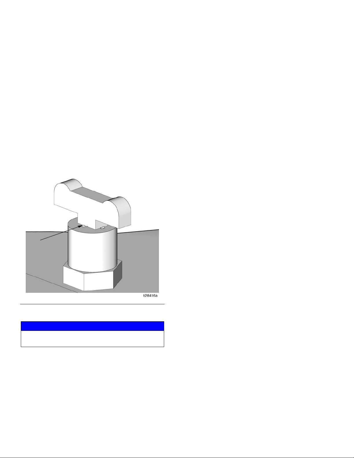
6. Remove the trapped air in the pump reservoir (K) by
slowly opening the cock valve (BB) until oil can be
seen coming out after all the air is released as
shown in F
IG. 6.
Supply Lines
1. If there are multiple pumps on the air line, close the
air regulators (B2) and bleed-type master air
valves (F) to all but one the pumps. If there is only
one pump, open its air regulator and bleed-type
master air valve.
2. Open the master air valve (F).
3. Set the air pressure to each pump at the lowest
pressure needed to get the desired results. See
Recommended Pressure provided in Tabl e 1:
Lubricant Output and Pressure - US or Tab l e 2 :
Lubricant Output and Pressure - Metric provided
on page 12.
4. Remove trapped air in the supply line (G) by
removing a plug or opening a fitting on the furthest
end of the supply line. Run the pump until oil comes
out. After oil free of air comes out, close the line.
Feeder Lines (S)
Fill each feeder line (S) with lubricant prior to connecting lines to the injector outlet.
FIG. 6
7. Close the cock valve (BB).
NOTICE
Always use lowest pressure possible to obtain desired
results.
Injectors (H)
For the following instructions, refer to Typical Installations, F
1. Check each injector (H) for proper operation. The
2. Adjust the injector output if needed to ensure that
IG. 1, page 4, for the following instructions.
injector stem should move when lubricant is discharged.
the output volume discharged is sufficient.
8 3A3169E
Installation
E
G
E
G
ol
Pressure Relief Procedure
Follow the Pressure Relief Procedure whenever
you see this symbol.
This equipment stays pressurized until pressure is
manually relieved. To help prevent serious injury from
pressurized fluid, such as skin injection, splashing
fluid and moving parts, follow the Pressure Relief
Procedure when you stop dispensing and before
cleaning, checking, or servicing the equipment.
1. Close the bleed-type master air valve (F) (required
in the system).
2. Close the shut-off valve (V) on the oil input sup-
ply pump/system (DD).
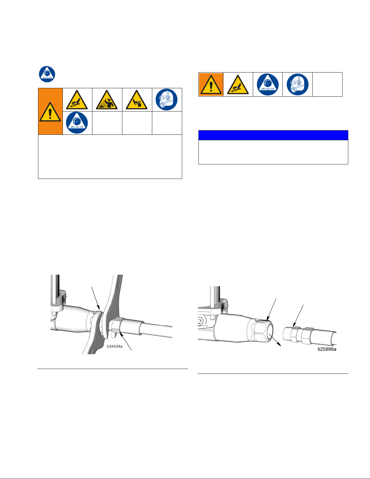
3. Relieve pressure in system using two wrenches
working in opposite directions on the pump outlet
(E) and lubrication line fitting (G) to slowly
loosen the fitting until it is loose and no more lubri-
cant or air is leaking out of the fitting (F
IG. 7).
Air Lock Procedure
An air lock occurs when a bubble or pocket of air prevents the normal flow of the lubricant.
NOTICE
Running the pump dry will cause an air lock. To prevent
an air lock, do not run the pump without lubricant.
Always refill the pump before it is empty.
If there is an air lock, first:
• Check that input supply oil line (CC) is connected
and that the oil flow is continuous to reservoir (K).
• Loosen the cock valve (BB) from the pump reser-
voir cover (L) to bleed out the air.
If the air lock persists:
1. Relieve pressure. See Pressure Relief Procedure,
page 9.
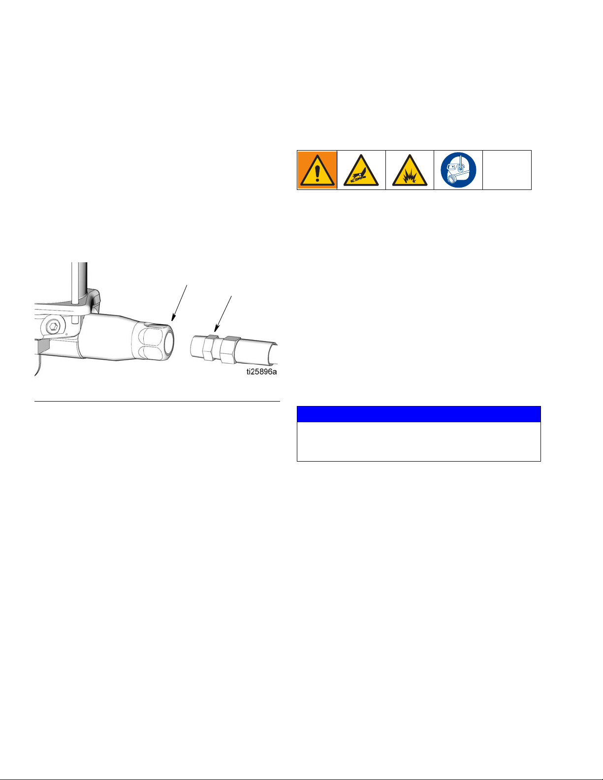
2. Disconnect the lubricant supply line (G) from the
pump outlet (E) (F
IG. 8).
FIG. 7
3A3169E 9
FIG. 8
3. Open the bleed-type master air valve (F, page 4).
4. Open the shut-off valve (V).
Operation
E
G
5. Run the pump a few strokes until oil (ol), free of air,
comes out of the pump outlet (E) (F
• It may take up to 20 the pump strokes to expel the
air from the pump and deliver a continuous flow of
oil. This will depend on the viscosity of the lubricant
and temperature.
• Allow a minimum of 5 seconds ON time for the forward stroke and 5 seconds OFF time for the return
stroke.
6. Connect the pump outlet (E) to the lubrication line
(G) (F
IG. 9).
FIG. 9
IG. 8).
Operation
Start Up
1. Verify reservoir is filled with lubricant and system
has been Primed (see Prime System, page 8).
2. Turn on the lubrication controller (J) power switch.
3. Program the lubrication controller to actuate the
solenoid valve (C).
NOTE: See the lubrication controller instruction
manual included with the system for these instructions.
4. Open air regulators and master air valves.
NOTE: Never allow the pump to run dry of the material
being the pumped.
NOTICE
Running the pump dry will cause an air lock. To prevent
an air lock, do not run the pump without lubricant.
Always refill the pump before it is empty.
At the start of a the pump cycle:
a. The air solenoid (C) supplies air to the pump
air inlet (P).
b. On the pump forward stroke, lubricant is dis-
pensed to all the injectors.
c. The pump is supplied with air through the air
inlet (R).
d. The pump makes a return stroke, venting the
system pressure back to the pump and resetting
all of the injector.
10 3A3169E
 Loading...