

Page 1
Instructions - Parts
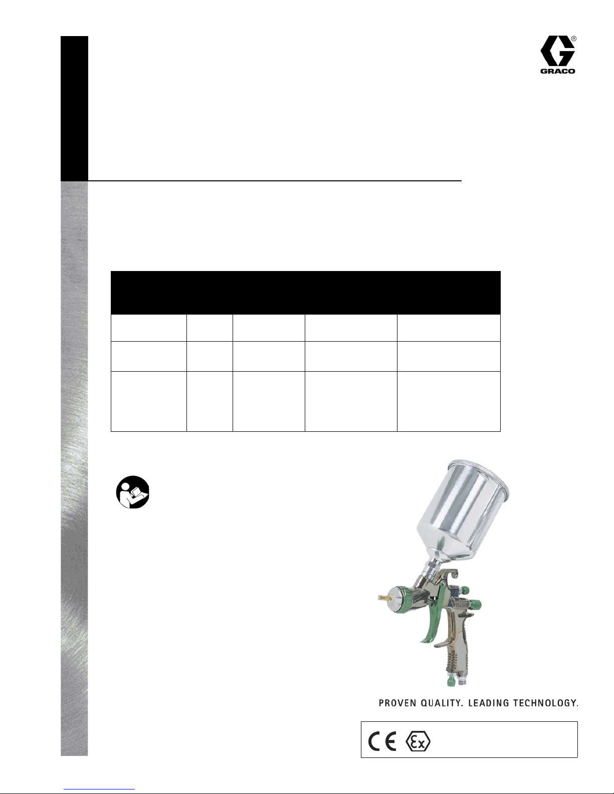
LT Series
Gravity Feed Air
Spray Guns
For professional spray application of liquid coating materials.
Models
Needle/
Part
Model
Mini-HVLP
Conventional
HVLP
* Maximum HVLP Compliant Pressure
No.
249346 1.0/0.039
249347 1.4/0.055
249348 1.8/0.071
249349 1.3/0.051
249350 1.4/0.055
249351 1.5/0.059
249352 1.8/0.071
Nozzle Size
(mm/in)
Maximum
Working Air
Pressure
100 psi
(0.7 MPa, 7 bar)
100 psi
(0.7 MPa, 7 bar)
100 psi
(0.7 MPa, 7 bar)
Recommended
Maximum Inbound
Air Pressure
29 psi
(0.20 MPa, 2.0 bar)*
60 psi
(0.41 MPa, 4.1 bar)
29 psi
(0.20 MPa, 2.0 bar)*
311104C
Important Safety Instructions
Read all warnings and instructions in this manual.
Save these instructions.
Contents
Warnings . . . . . . . . . . . . . . . . . . . . . . . . . . 2
Setup . . . . . . . . . . . . . . . . . . . . . . . . . . . . . 3
Troubleshooting . . . . . . . . . . . . . . . . . . . . 5
Service . . . . . . . . . . . . . . . . . . . . . . . . . . . . 6
Technical Data . . . . . . . . . . . . . . . . . . . . . . 7
Parts . . . . . . . . . . . . . . . . . . . . . . . . . . . . . . 8
Graco Standard Warranty . . . . . . . . . . . . 10
Graco Information . . . . . . . . . . . . . . . . . . 10
Graco Inc. P.O. Box 1441 Minneapolis, MN 55440-1441
Copyright 2005, Graco Inc. is registered to I.S. EN ISO 9001
II 2 G
Page 2
Warnings
Warnings
The following general warnings are related to the safe setup, use, grounding, maintenance and repair of this equipment. Additional more specific warnings may be found throughout the text of this manual where applicable.
WARNING
FIRE AND EXPLOSION HAZARD
Flammable fumes, such as solvent and paint fumes, in work area can ignite or explode. To help prevent
fire and explosion:
• Use equipment only in well ventilated area.
• Eliminate all ignition sources; such as pilot lights, cigarettes, portable electric lamps, and plastic drop
cloths (potential static arc).
• Keep work area free of debris, including solvent, rags and gasoline.
• Do not plug or unplug power cords or turn lights on or off when flammable fumes are present.
• Ground equipment and conductive objects in work area.
• If there is static sparking or you feel a shock, stop operation immediately. Do not use equipment
until you identify and correct the problem.
• Keep a fire extinguisher in the work area.
EQUIPMENT MISUSE HAZARD
Misuse can cause death or serious injury.
• Do not exceed the maximum working pressure or temperature rating of the lowest rated system
component. See Technical D ata in all equipment manuals.
• Use fluids and solvents that are compatible with equipment wetted parts. See Technical Data in all
equipment manuals. Read fluid and solvent manufacturer’s warnings.
• Check equipment daily. Repair or replace worn or damaged parts immediately.
• Do not alter or modify equipment.
• Use equipment only for its intended purpose. Call your Graco distributor for information.
• Route hoses and cables away from traffic areas, sharp edges, moving parts, and hot surfaces.
• Do not kink or over bend hoses or use hoses to pull equipment.
• Keep children and animals away from work area.
• Comply with all applicable safety regulations.
TOXIC FLUID OR FUMES HAZARD
Toxic fluids or fumes can cause serious injury or death if splashed in the eyes or on skin, inhaled, or swallowed.
• Read MSDS’s to know the specific hazards of the fluids you are using.
• Store hazardous fluid in approved containers, and dispose of it according to applicable guidelines.
PERSONAL PROTECTIVE EQUIPMENT
You must wear appropriate protective equipment when operating, servicing, or when in the operating area
of the equipment to help protect you from serious injury, including eye injury, inhalation of toxic fumes,
burns, and hearing loss. This equipment includes but is not limited to:
• Protective eyewear
• Clothing and respirator as recommended by the fluid and solvent manufacturer
• Gloves
• Hearing protection
PRESSURIZED EQUIPMENT HAZARD
Fluid from the gun/dispense valve, leaks, or ruptured components can splash in the eyes or on skin and
cause serious injury.
• Follow Pressure Relief Procedure in this manual, when you stop spraying and before cleaning,
checking, or servicing equipment.
• Tighten all fluid connections before operating the equipment.
• Check hoses, tubes, and couplings daily. Replace worn or damaged parts immediately.
2 311104C
Page 3
Setup
Setup
1. Install an air pressure regulator on gun air supply
line to control air pressure.
2. Install a shutoff valve downstream of the air regula-
tor to shut off gun air.
3. Connect a clean, dry, filtered air supply.
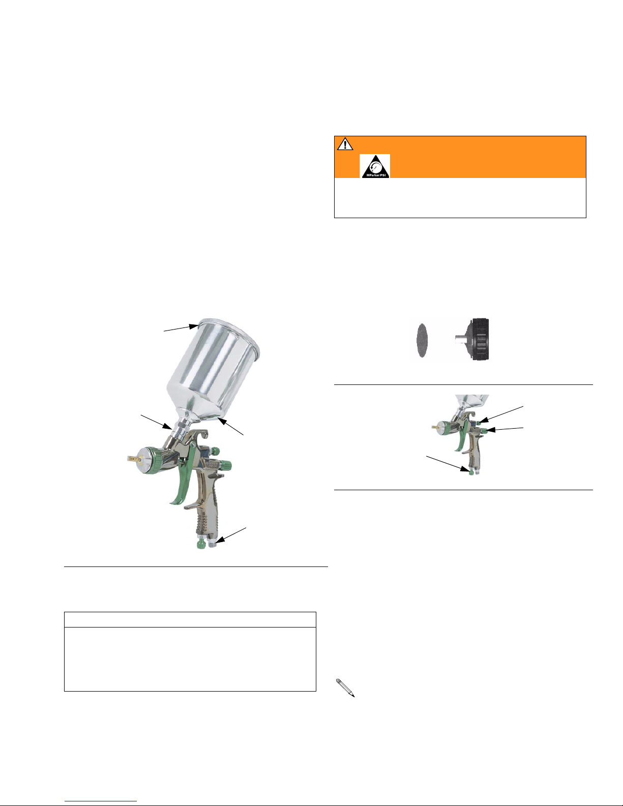
4. Connect air supply line to gun air inlet (21). FIG. 1.
Connect other end to shutoff valve.
5. Install fluid filter (29) into fluid inlet (6). Refer to
page 8.
6. Screw on gravity cup (30).
7. Remove gravity cup cover (A) and fill cup with sol-
vent to flush if this is first time using equipment.
A
6
30
Pressure Relief Procedure
WARNING
Follow Pressure Relief Procedure when you stop
spraying and before cleaning, checking, or servicing
equipment. Read warnings, page 2.
1. Turn off gun air supply.
Adjust Spray Pattern
1. Rotate air cap to change spray pattern direction.
IG. 2.
F
Vertical Pattern Adjustment
F
IG. 2
7
20
22
IG. 3
F
2. FIG. 3. For maximum fluid flow and to prevent pre-
mature fluid nozzle wear, turn fluid adjustment
knob (20) left until no trigger restriction is felt; trigger should be able to touch gun handle. Then turn
knob out 1/2 turn more.
F
21
IG. 1
3. If further fluid flow restriction is needed, use differ-
Flush Spray Gun
CAUTION
Flush spray gun before using it. Use solvent that is
compatible with gun wetted parts and fluid that will be
sprayed. Use lowest possible pressure, and spray into
grounded metal waste container. Read warnings,
page 2.
After flushing, follow Pressure Relief Procedure.
311104C 3
ent size needle/nozzle/air cap combination.
If necessary, fluid adjustment knob (20) can be
turned right to reduce volume of fluid output. However, continuously spraying with fluid adjustment
knob closed causes accelerated abrasive wear on
fluid needle and trigger/air valve shaft interface.
If fluid adjustment knob (20) is turned in all the way,
the gun emits only air.
Page 4

Setup
4. Test spray pattern and atomization while holding
gun about 6-8 inches (150-200 mm) from test
piece.
a. If pattern is too wide, turn pattern adjustment
knob (7) right to narrow pattern.
b. To create a round pattern, turn pattern adjust-
ment knob (7) fully right.
c. If pattern is too narrow, turn knob (7) left.
d. Check atomization. Increase gun air supply
pressure in 5 psi (34 kPa, 0.3 bar) increments
until you have the desired atomization.
CAUTION
Do not exceed maximum working air pressure shown
on front cover. Read warnings, page 2.
Applying Paint
For the best results:
• Keep gun perpendicular to surface and consistent
distance of about 6-8 inches (150-200 mm). Do not
angle the gun as you spray. F
IG. 4.
Daily Cleaning and Maintenance
WAR NING
Follow Pressure Relief Procedure when you stop
spraying and before cleaning, checking, or servicing
equipment. Read warnings, page 2.
CAUTION
• Do not submerge gun in solvent. Solvent dissolves
lubricant, dries out packings, and may clog air passages. You can immerse front end of gun in solvent
just until cup connection is covered.
• Do not use metal tools to clean air cap holes as this
may scratch them and distort the spray pattern.
• Use a compatible solvent.
1. Follow Pressure Relief Procedure, page 3.
2. Clean fluid and air line filters.
3. Check for fluid leakage from gun and fluid hoses.
Tighten fittings or replace equipment as needed.
F
IG. 4
• Use smooth, even strokes, with about 50% overlap.
• Mini-HVLP and HVLP Guns: Use a slightly slower
hand movement and make fewer passes than you
would with a conventional air spray gun. Take care
to avoid runs or sags.
4. Flush gun before changing colors and when you
are done spraying.
5. Remove cup (30) and filter (29) and clean them.
IG. 7.
F
6. Remove air cap (1) and nozzle (2) as instructed on
page 6 and soak them in compatible solvent.
CAUTION
Trigger gun and use gun tool (27) whenever you
tighten or remove nozzle (2) to avoid damaging needle seat (4) and nozzle,
7. Use a rag moistened in solvent to wipe down out-
side of gun.
8. Before reinstalling air cap and
nozzle, clean them and front of
gun with a soft-bristle brush
dipped into compatible solvent.
Do not use a wire brush or metal
tools. To clean out air cap holes,
use a soft implement, such as a
toothpick.
4 311104C
Page 5

Troubleshooting
Troubleshooting
WARNING
Follow Pressure Relief Procedure, page 3, before troubleshooting or servicing. Read warnings, page 2.
Problem Cause Solution
One side of air cap (1) dirty or clogged Clean air cap orifices. See page 4. Blow air through orifices until
a. Loose air cap (1). a. Tighten.
b. Dried or damaged air cap (1) or fluid nozzle (2). b. Rotate air cap 180°.
a. Atomization air pressure set too high. a. Reduce air pressure.
b. Spraying a thin material in too wide of a pattern. b. Increase material control by turning fluid adjustment knob (20) to
Air getting into paint stream.
a. Cup almost empty. a. Fill cup.
b. Dry needle packing (3). b. Loosen packing seat (4) and put a few drops of machine oil on
Spitting
c. Fluid nozzle (2) too loose. c. Tighten.
d. Dried material between nozzle (2) and gun
body.
e. Damaged needle seal e. Replace seal. See page 6.
Other spray pattern
problems
Unable to get round
pattern.
Will not spray. a. No air pressure at gun. a. Check air supply and air lines.
Fluid leaking from
packing nut (4).
Fluid nozzle (2) dripping. a. Dry packing (3). a. Lubricate.
Thin, coarse finish. a. Gun held too far from surface. a. Hold gun about 6-8 inches (150-200 mm) from surface.
Thick, dimpled finish
(resembling orange peel)
a. Gun not properly adjusted. a. See page 3.
b. Sluggish needle (18). b. Clean and lubricate.
Pattern adjustment knob (7) not seating properly. Clean or replace knob.
b. Cup empty. b. Fill cup.
c. Fluid adjustment knob (20) turned too far right. c. Adjust knob (20) to the left.
d. Fluid too thick for gravity feed. d. Thin material.
a. Packing nut (4) loose. a. Tighten, but not so tight as to grip needle.
b. Packing (3) worn or dry. b. Lubricate or replace.
b. Sluggish needle (18). b. Clean and lubricate.
c. Packing nut (4) too tight. c. Loosen.
d. Worn fluid nozzle or needle. d. Replace.
b. Atomization air pressure set to high. b. Reduce air pressure.
Gun held too close to surface. Hold gun about 6-8 inches (150-200 mm) from surface.
clean. If air cap holes are damaged, replace air cap.
If pattern follows air cap, problem is in air cap. Clean and inspect.
See page 4. If pattern is not corrected, replace air cap.
If pattern does not follow the air cap, the problem is with the fluid
nozzle. Clean and inspect the nozzle. See page 4. If the pattern
is not corrected, replace nozzle.
left, while reducing spray width by turning pattern adjustment
knob (7) to right.
Or increase material viscosity.
packing (3). Retighten seat (4).
d. Clean nozzle and front of gun. See page 4.
311104C 5
Page 6

Service
WAR NING
Service
3. Remove air valve shaft (8).
4. Remove fitting (17) with Allen wrench
(Mini-HVLP: 8 mm, Conventional/HVLP: 9 mm).
Follow Pressure Relief Procedure when you stop
spraying and before cleaning, checking, or servicing
equipment. Read warnings, page 2.
Preparation
1. Flush and clean gun before servicing. See page 4.
2. Follow Pressure Relief Procedure, page 3.
Air Cap, Nozzle, and Needle
1. Unscrew air cap (1). FIG. 6.
2. Trigger gun while you remove the nozzle (2) with
gun tool (27). See F
CAUTION
Trigger gun and use gun tool (27) whenever you
tighten or remove the nozzle (2) to avoid damage.
IG. 5.
3. Remove fluid adjustment knob (20) and spring (19).
IG. 6.
F
4. Pull needle (18) out the back of the gun.
5. Remove o-rings (13, 10) and holder (9) from fitting
(17).
6. Remove spring (16), piston (14), and o-ring (10).
7. Remove air valve seat (12) with o-ring (13) and
gasket (11).
8. Remove o-ring (10) and holder (9).
9. Replace parts as needed.
10. Reassemble in reverse order. Lubricate needle and
o-rings. Tighten o-ring packing holders (9) until
smooth movement of the air valve shaft (8) and air
valve piston (14) is achieved. DO NOT overtighten
the o-ring packing holders as a sluggish needle or
sticky trigger condition will result. Be sure to trigger
gun when installing nozzle (2).
30
29
6
21
5
11* 12
15*
28 27
2
27
YES NO
F
IG. 5
1220 19 18
IG. 6
F
Air Valve and Needle Packings
1. Remove retaining ring (26), gaskets (24), pin (25)
and trigger (23). F
IG. 7.
2. Remove packing nut (4) and packing (3).
8
26*
F
IG. 7
24
7
9*
4
3*
9*
10*
10*
13* 10* 14 16* 17
18
13*
21
23
2524
15*
22
19*
20
TI5088B
6 311104C
Page 7

Technical Data
Technical Data
Maximum Working Air Pressure . . . . . . . . . . . . . . . . . . . . . . . . . . . . . . . . . 100 psi (0.7 MPa, 7 bar)
Maximum HVLP Inbound Air Pressure. . . . . . . . . . . . . . . . . . . . . . . . . . . . 29 psi (0.2 MPa, 2 bar)
Fluid and Air Operating Temperature Range . . . . . . . . . . . . . . . . . . . . . . .32–109° F (0–43° C)
Weight
Mini-HVLP . . . . . . . . . . . . . . . . . . . . . . . . . . . . . . . . . . . . . . . . . . . . . .14 oz. (40 g)
Conventional. . . . . . . . . . . . . . . . . . . . . . . . . . . . . . . . . . . . . . . . . . . . .24 oz. (68 g)
HVLP . . . . . . . . . . . . . . . . . . . . . . . . . . . . . . . . . . . . . . . . . . . . . . . . . .24 oz. (68 g)
Air Inlet . . . . . . . . . . . . . . . . . . . . . . . . . . . . . . . . . . . . . . . . . . . . . . . . . . . .1/4-18 npsm (R1/4-19) compound thread
Wetted Parts . . . . . . . . . . . . . . . . . . . . . . . . . . . . . . . . . . . . . . . . . . . . . . . .Aluminum, stainless steel, brass, PTFE
Noise Data
Mini-HVLP Sound Pressure . . . . . . . . . . . . . . . . . . . . . . . . . . . . . . . . . . .
Sound Power . . . . . . . . . . . . . . . . . . . . . . . . . . . . . . . . . . . . .
Conventional
HVLP Sound Pressure . . . . . . . . . . . . . . . . . . . . . . . . . . . . . . . . . . .
Air Consumption
Mini-HVLP . . . . . . . . . . . . . . . . . . . . . . . . . . . . . . . . . . . . . . . . . . . . . .4.9 cfm at 29 psi (200 kPa, 2 bar)
Conventional. . . . . . . . . . . . . . . . . . . . . . . . . . . . . . . . . . . . . . . . . . . . .11.9 cfm at 41 psi (283 kPa, 2.8 bar)
HVLP . . . . . . . . . . . . . . . . . . . . . . . . . . . . . . . . . . . . . . . . . . . . . . . . . .11.4 cfm at 29 psi (200 kPa, 2 bar)
Sound Pressure . . . . . . . . . . . . . . . . . . . . . . . . . . . . . . . . . . .
Sound Power . . . . . . . . . . . . . . . . . . . . . . . . . . . . . . . . . . . . .
Sound Power . . . . . . . . . . . . . . . . . . . . . . . . . . . . . . . . . . . . .
64.08 dB(A)
73.97 dB(A)
79.01 dB(A)
88.91 dB(A)
72.98 dB(A)
82.88 dB(A)
311104C 7
Page 8

Parts
Mini-HVLP - Part No. 249346
Ref.
No. Part No. Description Qty.
1
15G123 Air Cap 1
2 15G124 Fluid Nozzle, 1.0 1
3* Needle Packing 1
4† Needle Packing Seat 1
5† Gun Body 1
6 15G127 Fluid Inlet Fitting 1
7
15G128 Pattern Adjustment Knob
8†
9*
10*
11*
12†
13*
14†
15*
Air Valve Shaft
Packing Holder
O-ring
Gasket
Air Valve Seat
O-ring
Air Valve Piston
O-ring
1
1
2
3
1
1
2
1
2
Parts
Ref.
No. Part No. Description Qty.
16*
17 15G135 Air Valve Fitting 1
18 15G136 Fluid Needle
19* Needle Spring 1
20† Fluid Adjustment Knob 1
21 15G139 Air Inlet Fitting 1
22†
23
24†
25
26*
27†
28†
29
30 15G148 Cup 1
15G141 Trigger
15G147 Fluid Filter
253713 Lid Gaskets for Cup 5
Air Valve Spring 1
Air Adjustment Valve
Gasket
Trigger Pin
Retaining Ring
Gun Wrench
Brush
1
1
2
1
1
1
1
1
* Parts included in Repair Kit 249510
† Parts not available.
30
29
27
11*
12
28
15*
6
21
5
7
10* 9*
4
3*
8
10*
18
9*
13*10* 14
16*
TI5088B
13*
17
2426*
24
23
8 311104C
25
15*
22
21
19*
20
Page 9

Conventional - Part Nos. 249347 and 249348 and
HVLP - Part Nos. 249349, 249350, 249351, and 249352
Includes:
Model No. Part No. Description Air Cap (1) Nozzle (2) Needle (18) Repair Kit
Conventional 249347 Conventional Air Spray, 1.4 15G157 15G151 15G170 249511
Conventional 249348 Conventional Air Spray, 1.8 15G157 15G153 15G156 249511
HVLP 249349 HVLP, 1.3 15G149 15G150 15G154 249511
HVLP 249350 HVLP, 1.4 15G149 15G151 15G170 249511
HVLP 249351 HVLP, 1.5 15G149 15G152 15G155 249511
HVLP 249352 HVLP, 1.8 15G149 15G153 15G156 249511
Parts
Ref.
No. Part No. Description Qty.
1
See table Air Cap 1
2 See table Fluid Nozzle, 1.0 1
3* Needle Packing 1
4† Needle Packing Seat 1
5† Gun Body 1
6 15G160 Fluid Inlet Fitting 1
7
15G161 Pattern Adjustment Knob
8†
9*
10*
11*
12†
13*
14†
15*
Air Valve Shaft
Packing Holder
O-ring
Gasket
Air Valve Seat
O-ring
Air Valve Piston
O-ring
1
1
2
3
1
1
2
1
2
Ref.
No. Part No. Description Qty.
16*
17 15G169 Air Valve Fitting 1
18 See table Fluid Needle
19* Needle Spring 1
20† Fluid Adjustment Knob 1
21 15G173 Air Inlet Fitting 1
22†
23
15G175 Trigger
24†
25†
26*
27†
28†
29
15G147 Fluid Filter
30 15G177 Cup 1
253713 Lid Gaskets for Cup 5
Air Valve Spring 1
Air Adjustment Valve
Gasket
Trigger Pin
Retaining Ring
Gun Wrench
Brush
1
1
2
1
1
1
1
1
* Parts included in Repair Kit 249511.
† Parts not available.
311104C 9
Page 10

Graco Standard Warranty
Graco warrants all equipment referenced in this document which is manufactured by Graco and bearing its name to be free from defects in
material and workmanship on the date of sale to the original purchaser for use. With the exception of any special, extended, or limited warranty
published by Graco, Graco will, for a period of twelve months from the date of sale, repair or replace any part of the equipment determined by
Graco to be defective. This warranty applies only when the equipment is installed, operated and maintained in accordance with Graco’s written
recommendations.
This warranty does not cover, and Graco shall not be liable for general wear and tear, or any malfunction, damage or wear caused by faulty
installation, misapplication, abrasion, corrosion, inadequate or improper maintenance, negligence, accident, tampering, or substitution of
non-Graco component parts. Nor shall Graco be liable for malfunction, damage or wear caused by the incompatibility of Graco equipment with
structures, accessories, equipment or materials not supplied by Graco, or the improper design, manufacture, installation, operation or
maintenance of structures, accessories, equipment or materials not supplied by Graco.
This warranty is conditioned upon the prepaid return of the equipment claimed to be defective to an authorized Graco distributor for verification of
the claimed defect. If the claimed defect is verified, Graco will repair or replace free of charge any defective parts. The equipment will be returned
to the original purchaser transportation prepaid. If inspection of the equipment does not disclose any defect in material or workmanship, repairs will
be made at a reasonable charge, which charges may include the costs of parts, labor, and transportation.
THIS WARRANTY IS EXCLUSIVE, AND IS IN LIEU OF ANY OTHER WARRANTIES, EXPRESS OR IMPLIED, INCLUDING BUT NOT LIMITED
TO WARRANTY OF MERCHANTABILITY OR WARRANTY OF FITNESS FOR A PARTICULAR PURPOSE.
Graco’s sole obligation and buyer’s sole remedy for any breach of warranty shall be as set forth above. The buyer agrees that no other remedy
(including, but not limited to, incidental or consequential damages for lost profits, lost sales, injury to person or property, or any other incidental or
consequential loss) shall be available. Any action for breach of warranty must be brought within two (2) years of the date of sale.
GRACO MAKES NO WARRANTY, AND DISCLAIMS ALL IMPLIED WARRANTIES OF MERCHANTABILITY AND FITNESS FOR A
PARTICULAR PURPOSE, IN CONNECTION WITH ACCESSORIES, EQUIPMENT, MATERIALS OR COMPONENTS SOLD BUT NOT
MANUFACTURED BY GRACO. These items sold, but not manufactured by Graco (such as electric motors, switches, hose, etc.), are subject to
the warranty, if any, of their manufacturer. Graco will provide purchaser with reasonable assistance in making any claim for breach of these
warranties.
In no event will Graco be liable for indirect, incidental, special or consequential damages resulting from Graco supplying equipment hereunder, or
the furnishing, performance, or use of any products or other goods sold hereto, whether due to a breach of contract, breach of warranty, the
negligence of Graco, or otherwise.
FOR GRACO CANADA CUSTOMERS
The Parties acknowledge that they have required that the present document, as well as all documents, notices and legal proceedings entered into,
given or instituted pursuant hereto or relating directly or indirectly hereto, be drawn up in English. Les parties reconnaissent avoir convenu que la
rédaction du présente document sera en Anglais, ainsi que tous documents, avis et procédures judiciaires exécutés, donnés ou intentés, à la suite
de ou en rapport, directement ou indirectement, avec les procédures concernées.
Graco Information
TO PLACE AN ORDER, contact your Graco distributor or call to identify the nearest distributor.
Phone: 612-623-6921 or Toll Free: 1-800-328-0211, Fax: 612-378-3505
All written and visual data contained in this document reflects the latest product information available at the time of publication.
Graco reserves the right to make changes at any time without notice.
International Offices: Belgium, China, Japan, Korea
GRACO INC. P.O. BOX 1441 MINNEAPOLIS, MN 55440-1441
This manual contains English. MM 311104
Graco Headquarters: Minneapolis
www.graco.com
311104C
7/2007
 Loading...