

Graco LineLazer v 3900, LineLazer v 5900 Operation Manual
Operation
ti27920a
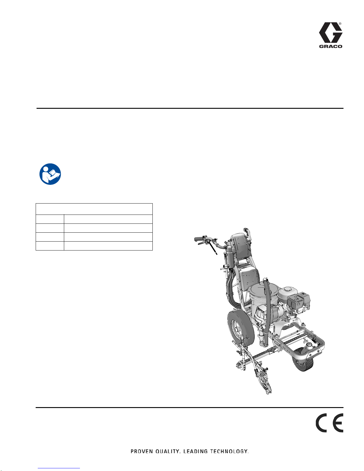
LineLazer™ V 3900, 5900 Airless Line Stripers
Standard Series and High Production (HP) Auto Series
For the application of line striping materials.
For professional use only.
For outdoor use only.
Not for use in explosive atmospheres or hazardous locations.
Maximum Operating Pressure: 3300 psi (22.8 MPa, 228 bar)
Important Safety Instructions
Read all warnings and instructions in this manual and in related manuals.
Be familiar with the controls and the proper usage of the equipment.
Save these instructions.
3A3388A
EN
Related Manuals:
3A3389 Parts
311254 Gun
309277 Pump
3A3428 Auto-Layout Applications Methods
Use only genuine Graco replacement pa rts .
The use of non-Graco replacement parts may void warranty.

Table of Contents
Models . . . . . . . . . . . . . . . . . . . . . . . . . . . . . . . . . . . 3
Warnings . . . . . . . . . . . . . . . . . . . . . . . . . . . . . . . . . 4
Important Laser Information for Units with Laser
Option . . . . . . . . . . . . . . . . . . . . . . . . . . . . . . 7
Battery Disposal . . . . . . . . . . . . . . . . . . . . . . . . . 8
Tip Selection . . . . . . . . . . . . . . . . . . . . . . . . . . . . . . 9
Component Identification (LLV 3900/5900) . . . . . 10
Grounding Procedure
(For Flammable Materials Only) . . . . . . . . . . 11
Pressure Relief Procedure . . . . . . . . . . . . . . . . . . 11
Setup/Startup . . . . . . . . . . . . . . . . . . . . . . . . . . . . . 12
SwitchTip and Guard Assembly . . . . . . . . . . . . 14
Gun Placement . . . . . . . . . . . . . . . . . . . . . . . . . . . 15
Install Guns . . . . . . . . . . . . . . . . . . . . . . . . . . . . 15
Position Gun . . . . . . . . . . . . . . . . . . . . . . . . . . . 15
Select Guns (Standard Series) . . . . . . . . . . . . . 15
Select Auto Guns (HP Auto Series) . . . . . . . . . 16
Gun Positions Chart . . . . . . . . . . . . . . . . . . . . . 17
Gun Arm Mounts . . . . . . . . . . . . . . . . . . . . . . . . 18
Change Gun Position
(Front and Back) . . . . . . . . . . . . . . . . . . . . . 18
Change Gun Position
(Left and Right) . . . . . . . . . . . . . . . . . . . . . . 18
Installation . . . . . . . . . . . . . . . . . . . . . . . . . . . . . 19
Trigger Sensor Adjustment . . . . . . . . . . . . . . . . 19
Gun Cable Adjustment . . . . . . . . . . . . . . . . . . . 20
Straight Line Adjustment . . . . . . . . . . . . . . . . . . 21
Handle Bar Adjustment . . . . . . . . . . . . . . . . . . . 21
Dot Laser (if applicable) . . . . . . . . . . . . . . . . . . 22
Cleanup . . . . . . . . . . . . . . . . . . . . . . . . . . . . . . . . . 23
Standard Series . . . . . . . . . . . . . . . . . . . . . . . . . . . 24
LineLazer V LiveLook Display . . . . . . . . . . . . . . . 25
Standard Series . . . . . . . . . . . . . . . . . . . . . . . . . 25
Initial Setup (Standard Series) . . . . . . . . . . . . . . 26
Striping Mode (Standard Series) . . . . . . . . . . . . 28
Measure Mode (Standard Series) . . . . . . . . . . . 29
Setup/Information . . . . . . . . . . . . . . . . . . . . . . . 30
Settings . . . . . . . . . . . . . . . . . . . . . . . . . . . . . . . 31
Information . . . . . . . . . . . . . . . . . . . . . . . . . . . . . 32
HP Auto Series . . . . . . . . . . . . . . . . . . . . . . . . . . . . 33
LineLazer V LiveLook Display . . . . . . . . . . . . . . . 34
HP Auto Series . . . . . . . . . . . . . . . . . . . . . . . . . 34
Initial Setup (HP Auto Series) . . . . . . . . . . . . . . 35
Striping Mode (HP Auto Series) . . . . . . . . . . . . 37
Measure Mode (HP Auto Series) . . . . . . . . . . . . 38
Layout Mode . . . . . . . . . . . . . . . . . . . . . . . . . . . 39
Stall Calculator . . . . . . . . . . . . . . . . . . . . . . . . . 40
Angle Calculator . . . . . . . . . . . . . . . . . . . . . . . . 41
Setup/Information . . . . . . . . . . . . . . . . . . . . . . . 43
Settings . . . . . . . . . . . . . . . . . . . . . . . . . . . . . . . 44
Information . . . . . . . . . . . . . . . . . . . . . . . . . . . . . 45
Data Logging . . . . . . . . . . . . . . . . . . . . . . . . . . . 47
Maintenance . . . . . . . . . . . . . . . . . . . . . . . . . . . . . . 48
LineLazer V 3900, 5900 . . . . . . . . . . . . . . . . . . 48
Troubleshooting . . . . . . . . . . . . . . . . . . . . . . . . . . . 49
Fluid Pump Runs Constantly . . . . . . . . . . . . . . . 54
Pinion Assembly/Clutch Armature/Clamp . . . . . . 55
Pinion Assembly/Clutch Armature Removal . . . 55
Installation . . . . . . . . . . . . . . . . . . . . . . . . . . . . . 56
Clamp Removal . . . . . . . . . . . . . . . . . . . . . . . . . 56
Clamp Installation . . . . . . . . . . . . . . . . . . . . . . . 56
Wiring Diagram (Standard Series) . . . . . . . . . . . . 57
Wiring Diagram (HP Auto Series) . . . . . . . . . . . . . 58
World Symbol Key . . . . . . . . . . . . . . . . . . . . . . . . . 59
Technical Specifications . . . . . . . . . . . . . . . . . . . . 60
Graco Standard Warranty . . . . . . . . . . . . . . . . . . . 64
2 3A3388A Operation

Models
Model: Standard
1 Manual Gun
17H449
17H450
17K577
17H451
17K638
17H452
17K579
17H453
Model:
17H454
17H455
17K580
17H456
17K636
17H457
17K581
17H458
Standard
1 Manual Gun
LineLazer V 3900
Standard
2 Manual Guns
LineLazer V 5900
Standard
2 Manual Guns
HP Auto
1 Auto Gun
with laser
HP Auto
1 Auto Gun
with laser
HP Auto
1 Auto Gun
1 Manual Gun
with laser
HP Auto
1 Auto Gun
1 Manual Gun
with laser
Models
HP Auto
2 Auto Guns
with laser
HP Auto
2 Auto Guns
with laser
* All auto guns can be actuated manually.
3A3388A Operation 3
Warnings
Warnings
The following warnings are for the setup, use, grounding, maintenance, and repair of this equipment. The exclamation
point symbol alerts you to a general warning and the hazard symbols refer to procedure-specific risks. When these symbols appear in the body of this manual or on warning labels, refer back to these Warnings. Product-specific hazard sym-
bols and warnings not covered in this section may appear throughout the body of this manual where applicable.
FIRE AND EXPLOSION HAZARD
Flammable fumes, such as solvent and paint fumes, in work area can ignite or explode. Paint or solvent flowing through the equipment can cause static sparking. To help prevent fire and explosion:
• Use equipment only in well ventilated area.
• Do not fill fuel tank while engine is running or hot; shut off engine and let it cool. Fuel is flammable and can
ignite or explode if spilled on hot surface.
• Eliminate all ignition sources; such as pilot lights, cigarettes, portable electric lamps, and plastic drop cloths
(potential static arc).
• Ground all equipment in the work area. See Grounding instructions.
• Never spray or flush solvent at high pressure.
• Keep work area free of debris, including solvent, rags and gasoline.
• Do not plug or unplug power cords, or turn power or light switches on or off when flammable fumes are present.
• Use only grounded hoses.
• Hold gun firmly to side of grounded pail when triggering into pail. Do not use pail liners unless they are antistatic or conductive.
• Stop operation immediately if static sparking occurs or you feel a shock. Do not use equipment until you
identify and correct the problem.
• Keep a working fire extinguisher in the work area.
SKIN INJECTION HAZARD
High-pressure spray is able to inject toxins into the body and cause serious bodily injury. In the event that
injection occurs, get immediate surgical treatment.
• Do not aim the gun at, or spray any person or animal.
• Keep hands and other body parts away from the discharge. For example, do not try to stop leaks with any
part of the body.
• Always use the nozzle tip guard. Do not spray without nozzle tip guard in place.
• Use Graco nozzle tips.
• Use caution when cleaning and changing nozzle tips. In the case where the n ozzle tip clogs while spraying,
follow the Pressure Relief Procedure for turning off the unit and relieving the pressure before removing
the nozzle tip to clean.
• Equipment maintains pressure after power is shut off. Do not leave the equipment energized or u nder pressure while unattended. Follow the Pressure Relief Procedure when the equipment is unattended or not
in use, and before servicing, cleaning, or removing parts.
• Check hoses and parts for signs of damage. Replace any damaged hoses or parts.
• This system is capable of producing 3300 psi. Use Graco replacement parts or accessories that are rated
a minimum of 3300 psi.
• Always engage the trigger lock when not spraying. Verify the trigger lock is functioning properly.
• Verify that all connections are secure before operating the unit.
• Know how to stop the unit and bleed pressure quickly. Be thoroughly familiar with the controls.
4 3A3388A Operation

Warnings
CARBON MONOXIDE HAZARD
Exhaust contains poisonous carbon monoxide, which is colorless and odorless. Breathing carbon monoxide
can cause death.
• Do not operate in an enclosed area.
EQUIPMENT MISUSE HAZARD
Misuse can cause death or serious injury.
• Do not operate the unit when fatigued or under the influence of drugs or alcohol.
• Do not exceed the maximum working pressure or temperature rating of the lowest rated system component. See Technical Data in all equipment manuals.
• Use fluids and solvents that are compatible with equ ipment wetted parts. See Technical Data in all equipment manuals. Read fluid and solvent manufacturer’s warnings. Fo r complete information about your material, request Safety Data Sheet (SDS) from distributor or retailer.
• Do not leave the work area while equipment is energized or under pressure.
• Turn off all equipment and follow the Pressure Relief Procedure when equipment is not in use.
• Check equipment daily. Repair or replace worn or damage d parts immediately with genuine manufacturer’s
replacement parts only.
• Do not alter or modify equipment. Alte rations or modifications may void agency approvals and create safety
hazards.
• Make sure all equipment is rated and approved for the environment in which you are using it.
• Use equipment only for its intended purpose. Call your distributor for information.
• Route hoses and cables away from traffic areas, sharp edges, moving parts, and hot surfaces.
• Do not kink or over bend hoses or use hoses to pull equipment.
• Keep children and animals away from work area.
• Comply with all applicable safety regulations.
PRESSURIZED ALUMINUM PARTS HAZARD
Use of fluids that are incompatible with aluminum in pressurized equip ment can ca use seriou s chemical r eaction and equipment rupture. Failure to follow this w arnin g ca n re su lt in death , ser io us inju ry , or pr op e rty damage.
• Do not use 1,1,1-trichloroethane, methylene chloride, other halogenated hydrocarbon solvents or fluids
containing such solvents.
• Do not use chlorine bleach.
• Many other fluids may contain chemicals that can react with aluminum. Contact your material supplier for
compatibility.
MOVING PARTS HAZARD
Moving parts can pinch, cut or amputate fingers and other body parts.
• Keep clear of moving parts.
• Do not operate equipment with protective guards or covers removed.
• Pressurized equipment can start without warning. Befor e checking, moving, or servicing equipment, follow
the Pressure Relief Procedure and disconnect all power sources.
TOXIC FLUID OR FUMES HAZARD
Toxic fluids or fumes can cause serious injury or death if splashed in the eyes or on skin, inhaled, or swallowed.
• Read Safety Data Sheet (SDS) to know the specific hazards of the fluids you are using.
• Store hazardous fluid in approved containers, and dispose of it according to applicable guide lines.
3A3388A Operation 5
Warnings
BURN HAZARD
Equipment surfaces and fluid that’s heated can become very hot during operation. To avoid severe burns:
• Do not touch hot fluid or equipment.
PERSONAL PROTECTIVE EQUIPMENT
Wear appropriate protective equipment when in the work area to help prevent serious injury, including eye
injury, hearing loss, inhalation of toxic fumes, and burns. This protective equipment includes but is not limited
to:
• Protective eyewear, and hearing protection.
• Respirators, protective clothing , an d glove s as re co m me n de d by the flu id an d so lve nt m anuf acturer.
BATTERY HAZARD
The battery may leak, explode, cause burns, or cause an explosion if mishandled. Contents of an open battery can cause severe irritation and/or chemical burns. If on skin, wash with soap and water. If in eyes, flush
with water for at least 15 minutes and get immediate medical attention.
• Only use the battery type specified for use with the equipment. See Technical Data.
• Replace battery only in well-ventilated area and away from flammable or combustible m aterials, including
paints and solvents.
• Do not dispose of battery in fire or heat above 50°C (122°F). The battery is capable of exploding.
• Do not throw into fire.
• Do not expose battery to water or rain.
• Do not disassemble, crush, or penetrate the battery.
• Do not use or charge a battery that is cracked or damaged.
• Follow local ordinances and/or regulations for disposal.
ELECTRIC SHOCK HAZARD
Hazardous voltage is present in control box while engine is running.
• Turn off engine before servicing equipment.
CALIFORNIA PROPOSITION 65
The engine exhaust from this product contains a chemical known to the State of California to cause cancer,
birth defects or other reproductive harm.
This product contains a chemical known to the State of California to cause cancer, birth de fects or other
reproductive harm. Wash hands after handling.
6 3A3388A Operation
Important Laser Information for Units with Laser Option
LASER LIGHT HAZARD: AVOID DIRECT EYE CONTACT
Eye exposure to Class IIIa/3R levels of laser light can potentia lly present an eye (retinal) injury hazar d, including spot blindness or other retinal injury. To avoid direct eye exposure:
• Never look directly in to a laser beam or point the beam into the eyes of others, even at long distances.
• Never shine the laser at mirror like surfaces which can cause specular reflections of the beam.
• Always set the laser at a height and angle that prevents the beam from shining into people’s eyes.
• Immediately terminate laser emissions if personnel, animals or reflective objects approach the beam.
• Always turn off laser when unattended.
• Do not remove any warning labels from the laser.
• Only properly trained laser operators are to use this product.
• Never allow beams to be aimed toward traffic, vehicles, or heavy equipment. Even when not damagi ng at
long distances, the high brightness of lasers can distract or disrupt vehicle operations.
• Never point a laser at an aircraft or law enforcement personnel. This is considered a felony in most locations, with the possibility of jail time, heavy fines or both.
• Do not disassemble laser product. Return to factory for all service procedures.
• Laser must be turned OFF when cleaning the lens, so as not to create unwanted laser refraction.
Warnings
LASER RADIATION HAZARD
Use of controls or adjustments or performance of procedures other than those specified herein may result in
hazardous radiation exposure.
• Do not attempt to open or disassemble the laser housing under any circumstances. Doing so may cause
exposure to potentially hazardous levels of laser radiation.
• No serviceable parts within. Unit is factory sealed.
FIRE AND EXPLOSION HAZARD
Connecting directly to a generator source can create a short or sparking under certain conditions.
• Only connect GL1700 to a dedicated 12 volt DC battery source.
3A3388A Operation 7

Warnings
Battery Disposal
Do not place batteries in the trash. Recycle batteries a ccording to local re gulations. To find a recycling locatio n in the
USA and Canada call 1-800-822-8837 or go to www.call2recycle.org.
i2
8 3A3388A Operation

Tip Selection
ti27606ati27606a
in.
in.
in.
ti27510a
in.
Tip Selection
(cm)
ti27505a
ti27506a
(cm)
(cm)
ti27507a
(cm)
LL5213* 2 (5)
LL5215* 2 (5)
LL5217
LL5219
LL5315
LL5317
LL5319
LL5321
LL5323
LL5325
LL5327
LL5329
LL5331
LL5333
LL5335
LL5355
4 (10)
4 (10)
4 (10)
4 (10)
4 (10)
4 (10)
4 (10)
4 (10)
4 (10)
4 (10)
4 (10)
4 (10)
4 (10)
4 (10)
LL5417 6 (15)
LL5419 6 (15)
LL5421 6 (15)
LL5423 6 (15)
LL5425 6 (15)
LL5427 6 (15)
LL5429 6 (15)
LL5431 6 (15)
LL5435 6 (15)
LL5621 12 (30)
LL5623 12 (30)
LL5625 12 (30)
LL5627 12 (30)
LL5629 12 (30)
LL5631 12 (30)
LL5635 12 (30)
LL5639 12 (30)
ti27508a
ti27509a
ti27605a
*Use 100 mesh filter to reduce tip clogs.
3A3388A Operation 9
Component Identification (LLV 3900/5900)
4
4
5
5
6
6
7
7
8
8
9
9
10
11
11
12
14
13
13
12
14
10
ti27502a
1 2
3
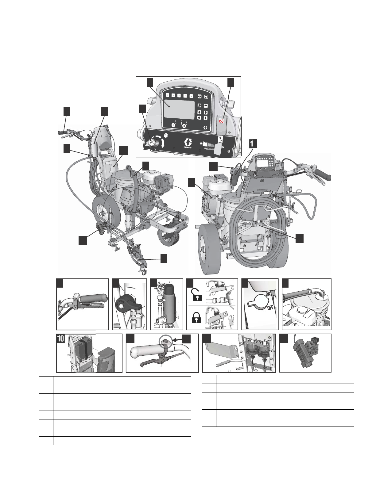
Component Identification (LLV 3900/5900)
1 Display
2 Pump ON/OFF switch & Engine Stop switch
3 Pressure control
4 Manual spray gun trigger
5 Prime/Pressure relief valve
6 Filter
7 Trigger safety
8 Engine ON/OFF switch
9 Drain and siphon tubes
*10 12 volt battery
11 Turn control
*12 Gun actuators
*13 Layout laser
*14 Auto spray gun control button
*HP Auto Series only. Upgrade to HP Auto Series with
P/N 25A527.
10 3A3388A Operation
Grounding Procedure (For Flammable Materials Only)
ti27607a
ti27608a
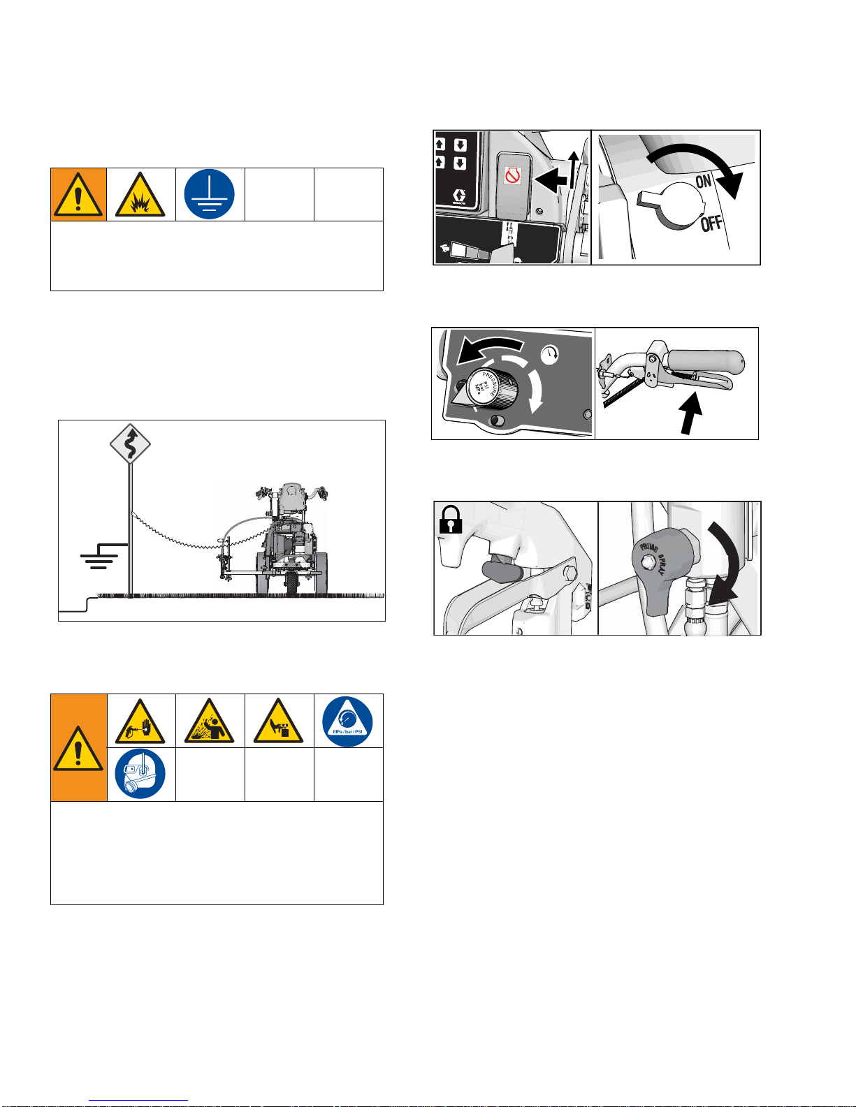
Grounding Procedure
(For Flammable Materials Only)
This equipment must be grounded to reduce the risk
of static sparking. Static sparking can cause fumes to
ignite or explode. Grounding provides a n escape wire
for the electric current.
1. Position striper so that the tires are not on pavement.
2. Striper is shipped with a grounding clamp. Grounding clamp must attach to grounded object (e.g.
metal sign post).
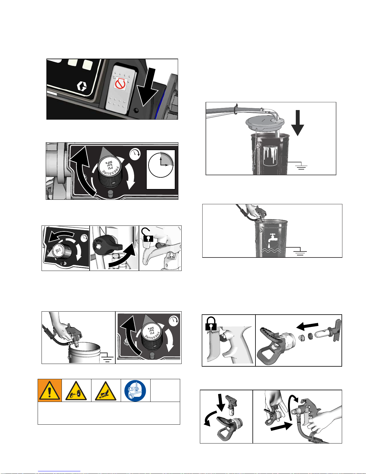
2. Set pump switch to OFF. Turn engine OFF.
ti27504a
3. Turn pressure control to lowest setting. Trigger all
guns to relieve pressure.
4. Engage all gun trigger locks. Turn prime valve
down.
v
ti27615a
Pressure Relief Procedure
This equipment stays pressurized until pressure is
manually relieved. To help prevent serious injury
from pressurized fluid, such as skin injection, splashing fluid and moving parts, follow the Pressure Re lief
Procedure when you stop dispensing and before
cleaning, checking, or servicing the equipment.
1. Perform Grounding Procedure if using flammable
materials.
5. If you suspect the spray tip or hose is clogged or
that pressure has not been fully relieved:
a. VERY SLOWLY loosen the tip guard retaining
nut or the hose end coupling to relieve pressu re
gradually.
b. Loosen the nut or coupling completely.
c. Clear the obstruction in the hose or tip.
3A3388A Operation 11
Setup/Startup
ti3307a
ti27610a
ti27611a
Pic 001
(same as pg.10)
ti27612a
Setup/Startup
This equipment stays pressurized until pressure is
manually relieved. To help prevent serious injury
from pressurized fluid, such as skin injection, splashing fluid and moving parts, follow the Pressure Re lief
Procedure when you stop spraying and before cleaning, checking, or servicing the equipment.
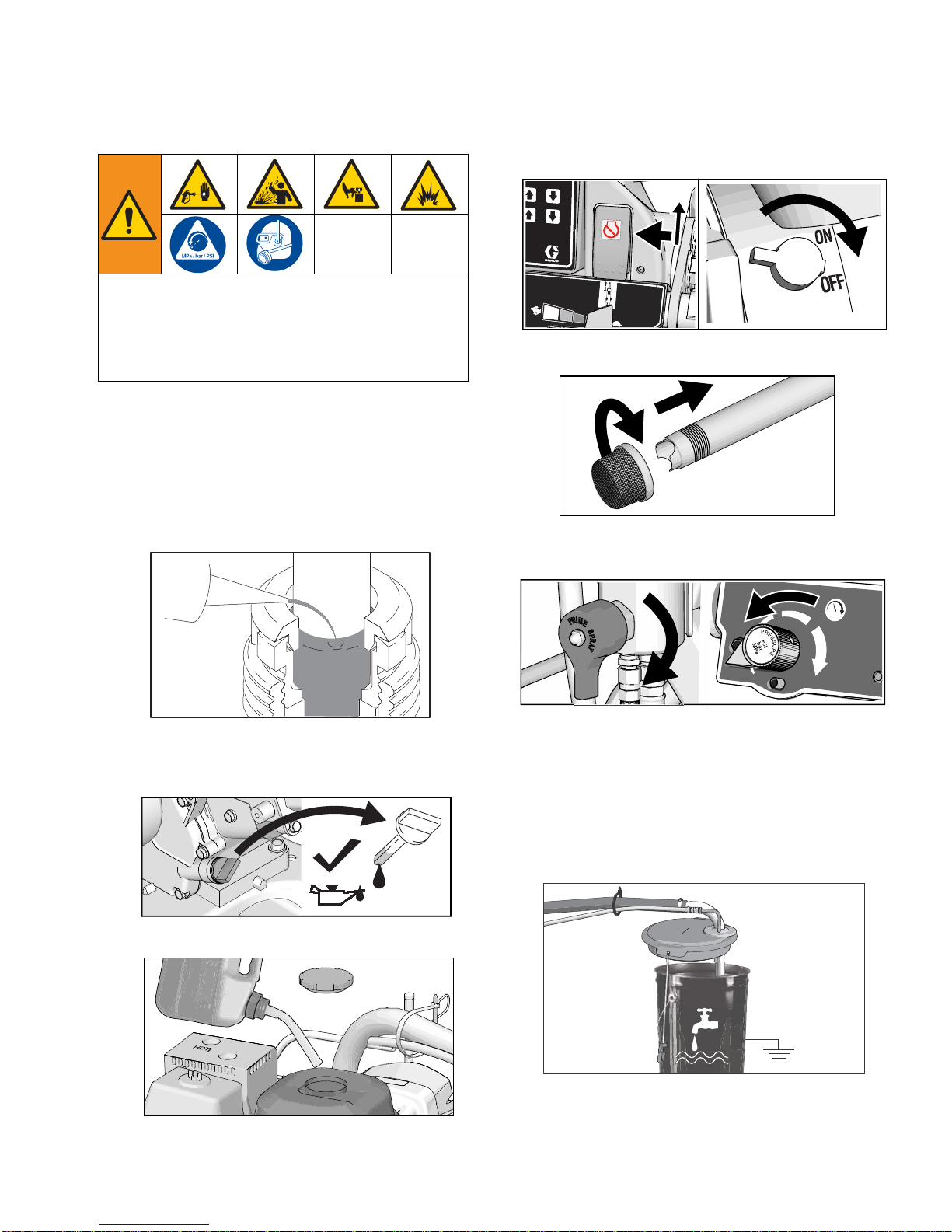
6. Set pump switch to OFF. Turn engine off.
ti27504a
7. If removed, install strainer.
1. Perform
Pressure Relief Procedure
, page 11
.
2. Perform Grounding Procedure (For Flammable
Materials Only), page 11, if using flammable mate-
rials.
3. Fill throat packing nut with Throat Seal Liquid (TSL)
to decrease packing wear.
4. Check engine oil level. Add SAE 10W-30 (summer)
or 5W-30 (winter). See engine manual.
8. Turn prime valve down. Turn pressure con tr ol coun terclockwise to lowest pressure.
ti27614a
NOTE: Minimum hose size allowable for proper
sprayer operation is 3/8 in. x 50 ft for LL3900/5900.
9. Place siphon tube set in grounded metal pail partially filled with flushing fluid. Attach ground wire to
true earth ground. Use water to flush water-base
paint and mineral spirits to flush oil-base paint and
storage oil.
5. Fill fuel tank.
12 3A3388A Operation
ti27613a
Setup/Startup
ti27616a
ti27617a
ti27618a
ti27618a
ti27619a
ti27620a
ti27618a
ti27767a
ti27833a
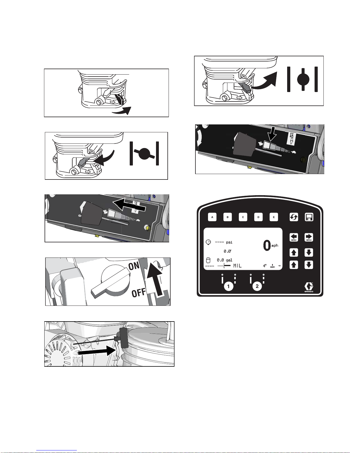
10. Start engine:
a. Move fuel valve to open.
b. Move choke to closed.
c. Set throttle to fast.
11. After engine starts, move choke to open.
ti27766a
12. Set throttle to desired setting.
13. Digital display is functional after engine starts.
d. Set engine switch to ON.
e. Pull starter cord.
3A3388A Operation 13
Setup/Startup
ti27770a
15s
ti27771a
ti27772a
ti27775a
ti27776a
14. Set pump switch to ON (pump is now active).
ti27769a
15. Increase pressure control enough to start pump.
Allow fluid to circulate for 15 seconds.
16. Turn pressure down, turn prime valve hor izon ta l .
Disengage gun trigger lock.
18. Inspect fittings for leaks. If leaks occur, turn spraye r
OFF immediately. Perform Pressure Relief Proce-
dure. Tighten leaky fittings. Repeat Setup/Startup,
steps 1 - 17. If no leaks, continue to trigger gun until
system is thoroughly flushed. Proceed to step 18.
19. Place siphon tube in paint pails.
ti27613a
20. Trigger all guns again into a flushing fluid pail until
paint appears. Assemble tips and guards.
17. Hold all guns against a grounded metal flushing pail.
Trigger guns and increase fluid pressure slowly u ntil
pump runs smoothly.
High-pressure spray is able to inject toxins into the
body and cause serious bodily injury. Do not stop
leaks with hand or rag.
ti27774a
SwitchTip and Guard Assembly
1. Engage trigger lock. Use end of SwitchTip to press
OneSeal into tip guard, with curve matching tip
bore.
2. Insert SwitchTip in tip bore and firmly thread assembly onto gun.
14 3A3388A Operation
Gun Placement
ti27777a
ti27778a
ti28129a
ti28130a
1
2
ti27781a
ti27782a
ti27782a
Gun Placement
Install Guns
1. Insert guns into gun holder. Tighten clamps.
Position Gun
2. Position gun: up/down, forward/reverse, left/right.
See Gun Positions Chart, page 17 for examples.
Another option can be to swing the gun out at an angle
and rotate the tip guard. This results in better visibility
for the user.
Select Guns (Standard Series)
3. Connect gun cables to left or right gun selector
plates.
ti27780a
a. One gun: Disconnect one gun selector plate
from trigger.
NOTE: When striping above a curb, the mounting clamp
can be rotated for clearance.
b. Both guns simultaneously: Adjust both gun
selector plates to the same position.
c. Solid-skip and skip-solid: Adjust solid-line gun
to position 1 and skip-line to position 2.
3A3388A Operation 15

Gun Placement
1s
ti27784a
ti27881a
ti27785a
Gun
1
Gun
2
Gun
1
Gun
2
Gun
1
Gun
2
Gun
1
Gun
2
Select Auto Guns (HP Auto Series)
1. Use the gun selector buttons to determine which
guns are active. Each gun selector has 3 settings:
continuous line, OFF and programmed line pattern.
2. Use the gun trigger control to actuate auto guns.
4 Examples:
16 3A3388A Operation
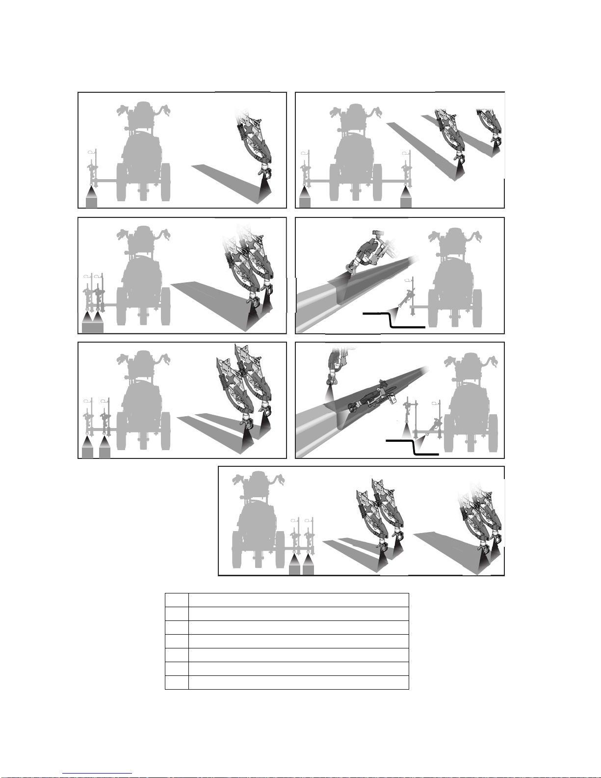
Gun Positions Chart
1
2
3
4
5
6
7
ti27786a
Gun Placement
1 One line
2 One line up to 24 in. (61cm) wide
3 Two lines
4 One line or two lines to spray around obstacles
5 One gun curb
6 Two gun curb
3A3388A Operation 17
7 Two lines or one line up to 24 in. (61 cm) wide
Gun Placement
ti27794a
ti27795a
ti27797a
ti27798a
ti27799a
ti27919a
ti27800a
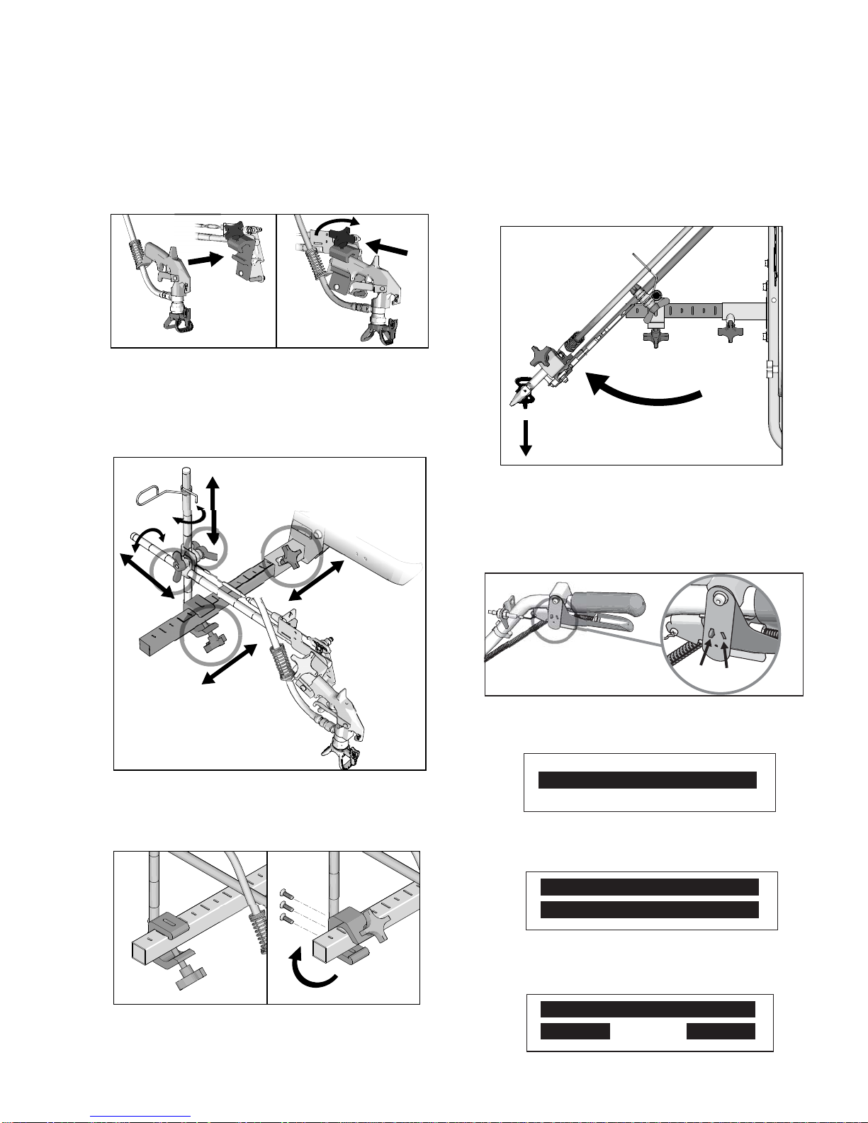
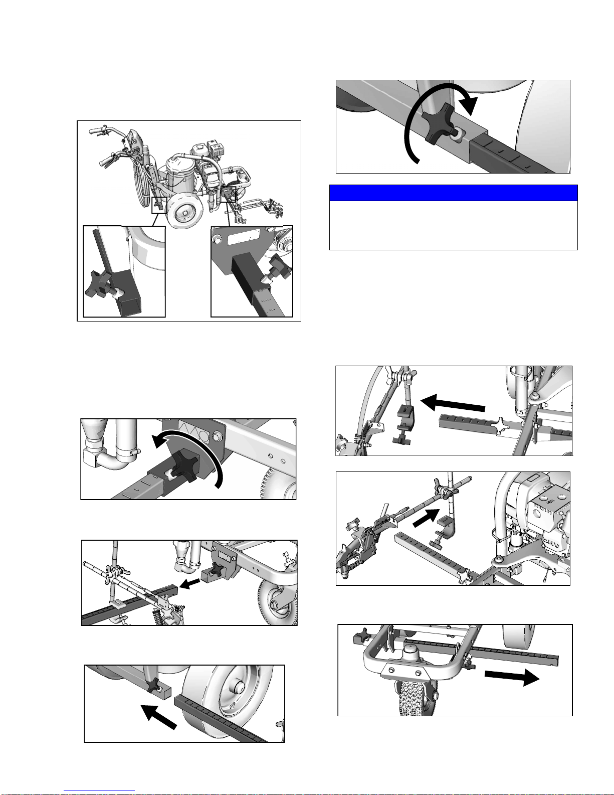
Gun Arm Mounts
This unit is equipped with front and rear gun arm
mounts.
Change Gun Position
4. Tighten gun arm knob into gun arm mounting slot.
NOTICE
Make sure all hoses, cables, and wires are properly
routed through brackets and do NOT rub on tire.
Contact with tire will result in damaged hoses, cables,
and wires.
Change Gun Position
(Left and Right)
Removal
1. Loosen vertical gun arm knob on gun arm mounting
bar and remove.
(Front and Back)
1. Loosen gun arm knob and remove from gun arm
mounting slot.
ti27796a
2. Slide gun arm assembly (including gun and hoses)
out from gun arm mounting slot.
3. Slide gun arm assembly into desired gun arm
mounting slot.
2. Extend mounting bar on opposite side of the
machine.
18 3A3388A Operation
Gun Placement
ti27801a
30.8
0.0
9
1490
mph
0
6
˝
mph
0
6
˝
ti27940a
30.8
0.0
9
1490
Standard Series
HP Auto Series
ti27883a
Installation
1. Install vertical gun mount onto gun bar.
NOTE: Make sure all hoses, cables, and wires are
properly routed through brackets.
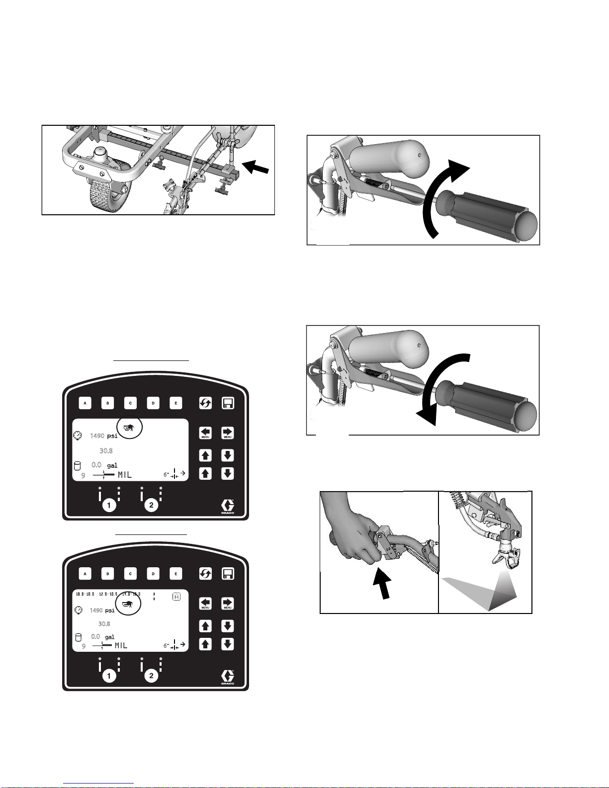
Trigger Sensor Adjustment
1. Start striper engine. Engage trigger. Spray icon
should appear simultaneously with start of fluid
spray.
No fluid spray
2. Turn screw in handle clockwise if spray icon
appears before fluid spray starts.
ti27802a
No spray icon
3. Turn screw in handle counterclockwise if fluid spray
starts before spray icon appears.
ti27803a
4. Continue adjusting screw in handle until timing of
spray icon and fluid spray are synchronized. Adjustment of the gun cables might be necessary.
3A3388A Operation 19
Gun Placement
Standard Series
HP Auto Series
ti27804a
ti27805a
ti27806a
ti27807a
ti27809a
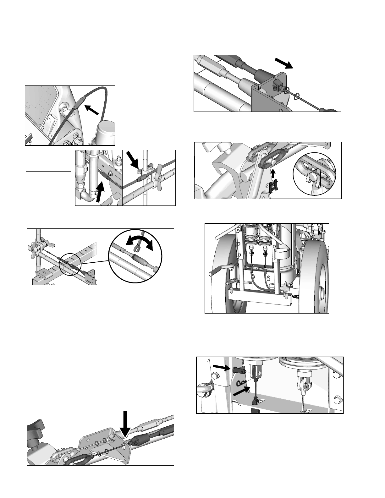
Gun Cable Adjustment
Adjusting the gun cable will increase or decrease the
gap between the trigger plate and the gun trigger. To
adjust trigger gap, perform the steps below.
ti27884a
ti27885a
1. Use wrench to loosen locking nut on cable adjuster.
3. Insert plastic cable retainer into cable bracket hole.
4. Install cable end onto trigger plate pin and install
clip.
5. Route cable around unit and up through cable holes
behind hose mount.
2. Loosen or tighten adjuster until desired result is
achieved. NOTE: More thread exposed means less
gap between gun trigger and trigger plate.
3. Use wrench to tighten locking nut on the adjuster.
Adding Gun Cable (HP Auto Series)
The HP Auto Series can be equipped with two gun actuators. Each gun actuator is capable of operating one
cable.
1. Select cable end with adjuster.
2. Install exposed cable through cable bracket slot.
ti27808a
6. Route cable end loop through rectangular hole in
bracket and insert plastic cable retainer into the
actuator bracket. Install cable end onto actuator rod
and install pin.
20 3A3388A Operation
 Loading...