

Page 1
Operation
ti27920a
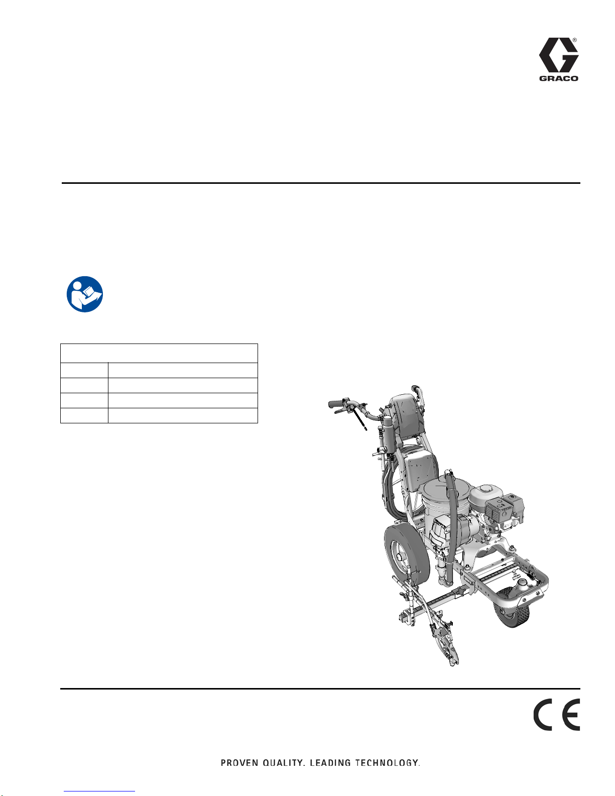
LineLazer™ V 3900, 5900 Airless Line Stripers
Standard Series and High Production (HP) Auto Series
For the application of line striping materials.
For professional use only.
For outdoor use only.
Not for use in explosive atmospheres or hazardous locations.
Maximum Operating Pressure: 3300 psi (22.8 MPa, 228 bar)
Important Safety Instructions
Read all warnings and instructions in this manual and in related manuals.
Be familiar with the controls and the proper usage of the equipment.
Save these instructions.
3A3388A
EN
Related Manuals:
3A3389 Parts
311254 Gun
309277 Pump
3A3428 Auto-Layout Applications Methods
Use only genuine Graco replacement pa rts .
The use of non-Graco replacement parts may void warranty.
Page 2

Table of Contents
Models . . . . . . . . . . . . . . . . . . . . . . . . . . . . . . . . . . . 3
Warnings . . . . . . . . . . . . . . . . . . . . . . . . . . . . . . . . . 4
Important Laser Information for Units with Laser
Option . . . . . . . . . . . . . . . . . . . . . . . . . . . . . . 7
Battery Disposal . . . . . . . . . . . . . . . . . . . . . . . . . 8
Tip Selection . . . . . . . . . . . . . . . . . . . . . . . . . . . . . . 9
Component Identification (LLV 3900/5900) . . . . . 10
Grounding Procedure
(For Flammable Materials Only) . . . . . . . . . . 11
Pressure Relief Procedure . . . . . . . . . . . . . . . . . . 11
Setup/Startup . . . . . . . . . . . . . . . . . . . . . . . . . . . . . 12
SwitchTip and Guard Assembly . . . . . . . . . . . . 14
Gun Placement . . . . . . . . . . . . . . . . . . . . . . . . . . . 15
Install Guns . . . . . . . . . . . . . . . . . . . . . . . . . . . . 15
Position Gun . . . . . . . . . . . . . . . . . . . . . . . . . . . 15
Select Guns (Standard Series) . . . . . . . . . . . . . 15
Select Auto Guns (HP Auto Series) . . . . . . . . . 16
Gun Positions Chart . . . . . . . . . . . . . . . . . . . . . 17
Gun Arm Mounts . . . . . . . . . . . . . . . . . . . . . . . . 18
Change Gun Position
(Front and Back) . . . . . . . . . . . . . . . . . . . . . 18
Change Gun Position
(Left and Right) . . . . . . . . . . . . . . . . . . . . . . 18
Installation . . . . . . . . . . . . . . . . . . . . . . . . . . . . . 19
Trigger Sensor Adjustment . . . . . . . . . . . . . . . . 19
Gun Cable Adjustment . . . . . . . . . . . . . . . . . . . 20
Straight Line Adjustment . . . . . . . . . . . . . . . . . . 21
Handle Bar Adjustment . . . . . . . . . . . . . . . . . . . 21
Dot Laser (if applicable) . . . . . . . . . . . . . . . . . . 22
Cleanup . . . . . . . . . . . . . . . . . . . . . . . . . . . . . . . . . 23
Standard Series . . . . . . . . . . . . . . . . . . . . . . . . . . . 24
LineLazer V LiveLook Display . . . . . . . . . . . . . . . 25
Standard Series . . . . . . . . . . . . . . . . . . . . . . . . . 25
Initial Setup (Standard Series) . . . . . . . . . . . . . . 26
Striping Mode (Standard Series) . . . . . . . . . . . . 28
Measure Mode (Standard Series) . . . . . . . . . . . 29
Setup/Information . . . . . . . . . . . . . . . . . . . . . . . 30
Settings . . . . . . . . . . . . . . . . . . . . . . . . . . . . . . . 31
Information . . . . . . . . . . . . . . . . . . . . . . . . . . . . . 32
HP Auto Series . . . . . . . . . . . . . . . . . . . . . . . . . . . . 33
LineLazer V LiveLook Display . . . . . . . . . . . . . . . 34
HP Auto Series . . . . . . . . . . . . . . . . . . . . . . . . . 34
Initial Setup (HP Auto Series) . . . . . . . . . . . . . . 35
Striping Mode (HP Auto Series) . . . . . . . . . . . . 37
Measure Mode (HP Auto Series) . . . . . . . . . . . . 38
Layout Mode . . . . . . . . . . . . . . . . . . . . . . . . . . . 39
Stall Calculator . . . . . . . . . . . . . . . . . . . . . . . . . 40
Angle Calculator . . . . . . . . . . . . . . . . . . . . . . . . 41
Setup/Information . . . . . . . . . . . . . . . . . . . . . . . 43
Settings . . . . . . . . . . . . . . . . . . . . . . . . . . . . . . . 44
Information . . . . . . . . . . . . . . . . . . . . . . . . . . . . . 45
Data Logging . . . . . . . . . . . . . . . . . . . . . . . . . . . 47
Maintenance . . . . . . . . . . . . . . . . . . . . . . . . . . . . . . 48
LineLazer V 3900, 5900 . . . . . . . . . . . . . . . . . . 48
Troubleshooting . . . . . . . . . . . . . . . . . . . . . . . . . . . 49
Fluid Pump Runs Constantly . . . . . . . . . . . . . . . 54
Pinion Assembly/Clutch Armature/Clamp . . . . . . 55
Pinion Assembly/Clutch Armature Removal . . . 55
Installation . . . . . . . . . . . . . . . . . . . . . . . . . . . . . 56
Clamp Removal . . . . . . . . . . . . . . . . . . . . . . . . . 56
Clamp Installation . . . . . . . . . . . . . . . . . . . . . . . 56
Wiring Diagram (Standard Series) . . . . . . . . . . . . 57
Wiring Diagram (HP Auto Series) . . . . . . . . . . . . . 58
World Symbol Key . . . . . . . . . . . . . . . . . . . . . . . . . 59
Technical Specifications . . . . . . . . . . . . . . . . . . . . 60
Graco Standard Warranty . . . . . . . . . . . . . . . . . . . 64
2 3A3388A Operation
Page 3

Models
Model: Standard
1 Manual Gun
17H449
17H450
17K577
17H451
17K638
17H452
17K579
17H453
Model:
17H454
17H455
17K580
17H456
17K636
17H457
17K581
17H458
Standard
1 Manual Gun
LineLazer V 3900
Standard
2 Manual Guns
LineLazer V 5900
Standard
2 Manual Guns
HP Auto
1 Auto Gun
with laser
HP Auto
1 Auto Gun
with laser
HP Auto
1 Auto Gun
1 Manual Gun
with laser
HP Auto
1 Auto Gun
1 Manual Gun
with laser
Models
HP Auto
2 Auto Guns
with laser
HP Auto
2 Auto Guns
with laser
* All auto guns can be actuated manually.
3A3388A Operation 3
Page 4
Warnings
Warnings
The following warnings are for the setup, use, grounding, maintenance, and repair of this equipment. The exclamation
point symbol alerts you to a general warning and the hazard symbols refer to procedure-specific risks. When these symbols appear in the body of this manual or on warning labels, refer back to these Warnings. Product-specific hazard sym-
bols and warnings not covered in this section may appear throughout the body of this manual where applicable.
FIRE AND EXPLOSION HAZARD
Flammable fumes, such as solvent and paint fumes, in work area can ignite or explode. Paint or solvent flowing through the equipment can cause static sparking. To help prevent fire and explosion:
• Use equipment only in well ventilated area.
• Do not fill fuel tank while engine is running or hot; shut off engine and let it cool. Fuel is flammable and can
ignite or explode if spilled on hot surface.
• Eliminate all ignition sources; such as pilot lights, cigarettes, portable electric lamps, and plastic drop cloths
(potential static arc).
• Ground all equipment in the work area. See Grounding instructions.
• Never spray or flush solvent at high pressure.
• Keep work area free of debris, including solvent, rags and gasoline.
• Do not plug or unplug power cords, or turn power or light switches on or off when flammable fumes are present.
• Use only grounded hoses.
• Hold gun firmly to side of grounded pail when triggering into pail. Do not use pail liners unless they are antistatic or conductive.
• Stop operation immediately if static sparking occurs or you feel a shock. Do not use equipment until you
identify and correct the problem.
• Keep a working fire extinguisher in the work area.
SKIN INJECTION HAZARD
High-pressure spray is able to inject toxins into the body and cause serious bodily injury. In the event that
injection occurs, get immediate surgical treatment.
• Do not aim the gun at, or spray any person or animal.
• Keep hands and other body parts away from the discharge. For example, do not try to stop leaks with any
part of the body.
• Always use the nozzle tip guard. Do not spray without nozzle tip guard in place.
• Use Graco nozzle tips.
• Use caution when cleaning and changing nozzle tips. In the case where the n ozzle tip clogs while spraying,
follow the Pressure Relief Procedure for turning off the unit and relieving the pressure before removing
the nozzle tip to clean.
• Equipment maintains pressure after power is shut off. Do not leave the equipment energized or u nder pressure while unattended. Follow the Pressure Relief Procedure when the equipment is unattended or not
in use, and before servicing, cleaning, or removing parts.
• Check hoses and parts for signs of damage. Replace any damaged hoses or parts.
• This system is capable of producing 3300 psi. Use Graco replacement parts or accessories that are rated
a minimum of 3300 psi.
• Always engage the trigger lock when not spraying. Verify the trigger lock is functioning properly.
• Verify that all connections are secure before operating the unit.
• Know how to stop the unit and bleed pressure quickly. Be thoroughly familiar with the controls.
4 3A3388A Operation
Page 5

Warnings
CARBON MONOXIDE HAZARD
Exhaust contains poisonous carbon monoxide, which is colorless and odorless. Breathing carbon monoxide
can cause death.
• Do not operate in an enclosed area.
EQUIPMENT MISUSE HAZARD
Misuse can cause death or serious injury.
• Do not operate the unit when fatigued or under the influence of drugs or alcohol.
• Do not exceed the maximum working pressure or temperature rating of the lowest rated system component. See Technical Data in all equipment manuals.
• Use fluids and solvents that are compatible with equ ipment wetted parts. See Technical Data in all equipment manuals. Read fluid and solvent manufacturer’s warnings. Fo r complete information about your material, request Safety Data Sheet (SDS) from distributor or retailer.
• Do not leave the work area while equipment is energized or under pressure.
• Turn off all equipment and follow the Pressure Relief Procedure when equipment is not in use.
• Check equipment daily. Repair or replace worn or damage d parts immediately with genuine manufacturer’s
replacement parts only.
• Do not alter or modify equipment. Alte rations or modifications may void agency approvals and create safety
hazards.
• Make sure all equipment is rated and approved for the environment in which you are using it.
• Use equipment only for its intended purpose. Call your distributor for information.
• Route hoses and cables away from traffic areas, sharp edges, moving parts, and hot surfaces.
• Do not kink or over bend hoses or use hoses to pull equipment.
• Keep children and animals away from work area.
• Comply with all applicable safety regulations.
PRESSURIZED ALUMINUM PARTS HAZARD
Use of fluids that are incompatible with aluminum in pressurized equip ment can ca use seriou s chemical r eaction and equipment rupture. Failure to follow this w arnin g ca n re su lt in death , ser io us inju ry , or pr op e rty damage.
• Do not use 1,1,1-trichloroethane, methylene chloride, other halogenated hydrocarbon solvents or fluids
containing such solvents.
• Do not use chlorine bleach.
• Many other fluids may contain chemicals that can react with aluminum. Contact your material supplier for
compatibility.
MOVING PARTS HAZARD
Moving parts can pinch, cut or amputate fingers and other body parts.
• Keep clear of moving parts.
• Do not operate equipment with protective guards or covers removed.
• Pressurized equipment can start without warning. Befor e checking, moving, or servicing equipment, follow
the Pressure Relief Procedure and disconnect all power sources.
TOXIC FLUID OR FUMES HAZARD
Toxic fluids or fumes can cause serious injury or death if splashed in the eyes or on skin, inhaled, or swallowed.
• Read Safety Data Sheet (SDS) to know the specific hazards of the fluids you are using.
• Store hazardous fluid in approved containers, and dispose of it according to applicable guide lines.
3A3388A Operation 5
Page 6
Warnings
BURN HAZARD
Equipment surfaces and fluid that’s heated can become very hot during operation. To avoid severe burns:
• Do not touch hot fluid or equipment.
PERSONAL PROTECTIVE EQUIPMENT
Wear appropriate protective equipment when in the work area to help prevent serious injury, including eye
injury, hearing loss, inhalation of toxic fumes, and burns. This protective equipment includes but is not limited
to:
• Protective eyewear, and hearing protection.
• Respirators, protective clothing , an d glove s as re co m me n de d by the flu id an d so lve nt m anuf acturer.
BATTERY HAZARD
The battery may leak, explode, cause burns, or cause an explosion if mishandled. Contents of an open battery can cause severe irritation and/or chemical burns. If on skin, wash with soap and water. If in eyes, flush
with water for at least 15 minutes and get immediate medical attention.
• Only use the battery type specified for use with the equipment. See Technical Data.
• Replace battery only in well-ventilated area and away from flammable or combustible m aterials, including
paints and solvents.
• Do not dispose of battery in fire or heat above 50°C (122°F). The battery is capable of exploding.
• Do not throw into fire.
• Do not expose battery to water or rain.
• Do not disassemble, crush, or penetrate the battery.
• Do not use or charge a battery that is cracked or damaged.
• Follow local ordinances and/or regulations for disposal.
ELECTRIC SHOCK HAZARD
Hazardous voltage is present in control box while engine is running.
• Turn off engine before servicing equipment.
CALIFORNIA PROPOSITION 65
The engine exhaust from this product contains a chemical known to the State of California to cause cancer,
birth defects or other reproductive harm.
This product contains a chemical known to the State of California to cause cancer, birth de fects or other
reproductive harm. Wash hands after handling.
6 3A3388A Operation
Page 7
Important Laser Information for Units with Laser Option
LASER LIGHT HAZARD: AVOID DIRECT EYE CONTACT
Eye exposure to Class IIIa/3R levels of laser light can potentia lly present an eye (retinal) injury hazar d, including spot blindness or other retinal injury. To avoid direct eye exposure:
• Never look directly in to a laser beam or point the beam into the eyes of others, even at long distances.
• Never shine the laser at mirror like surfaces which can cause specular reflections of the beam.
• Always set the laser at a height and angle that prevents the beam from shining into people’s eyes.
• Immediately terminate laser emissions if personnel, animals or reflective objects approach the beam.
• Always turn off laser when unattended.
• Do not remove any warning labels from the laser.
• Only properly trained laser operators are to use this product.
• Never allow beams to be aimed toward traffic, vehicles, or heavy equipment. Even when not damagi ng at
long distances, the high brightness of lasers can distract or disrupt vehicle operations.
• Never point a laser at an aircraft or law enforcement personnel. This is considered a felony in most locations, with the possibility of jail time, heavy fines or both.
• Do not disassemble laser product. Return to factory for all service procedures.
• Laser must be turned OFF when cleaning the lens, so as not to create unwanted laser refraction.
Warnings
LASER RADIATION HAZARD
Use of controls or adjustments or performance of procedures other than those specified herein may result in
hazardous radiation exposure.
• Do not attempt to open or disassemble the laser housing under any circumstances. Doing so may cause
exposure to potentially hazardous levels of laser radiation.
• No serviceable parts within. Unit is factory sealed.
FIRE AND EXPLOSION HAZARD
Connecting directly to a generator source can create a short or sparking under certain conditions.
• Only connect GL1700 to a dedicated 12 volt DC battery source.
3A3388A Operation 7
Page 8

Warnings
Battery Disposal
Do not place batteries in the trash. Recycle batteries a ccording to local re gulations. To find a recycling locatio n in the
USA and Canada call 1-800-822-8837 or go to www.call2recycle.org.
i2
8 3A3388A Operation
Page 9

Tip Selection
ti27606ati27606a
in.
in.
in.
ti27510a
in.
Tip Selection
(cm)
ti27505a
ti27506a
(cm)
(cm)
ti27507a
(cm)
LL5213* 2 (5)
LL5215* 2 (5)
LL5217
LL5219
LL5315
LL5317
LL5319
LL5321
LL5323
LL5325
LL5327
LL5329
LL5331
LL5333
LL5335
LL5355
4 (10)
4 (10)
4 (10)
4 (10)
4 (10)
4 (10)
4 (10)
4 (10)
4 (10)
4 (10)
4 (10)
4 (10)
4 (10)
4 (10)
LL5417 6 (15)
LL5419 6 (15)
LL5421 6 (15)
LL5423 6 (15)
LL5425 6 (15)
LL5427 6 (15)
LL5429 6 (15)
LL5431 6 (15)
LL5435 6 (15)
LL5621 12 (30)
LL5623 12 (30)
LL5625 12 (30)
LL5627 12 (30)
LL5629 12 (30)
LL5631 12 (30)
LL5635 12 (30)
LL5639 12 (30)
ti27508a
ti27509a
ti27605a
*Use 100 mesh filter to reduce tip clogs.
3A3388A Operation 9
Page 10
Component Identification (LLV 3900/5900)
4
4
5
5
6
6
7
7
8
8
9
9
10
11
11
12
14
13
13
12
14
10
ti27502a
1 2
3
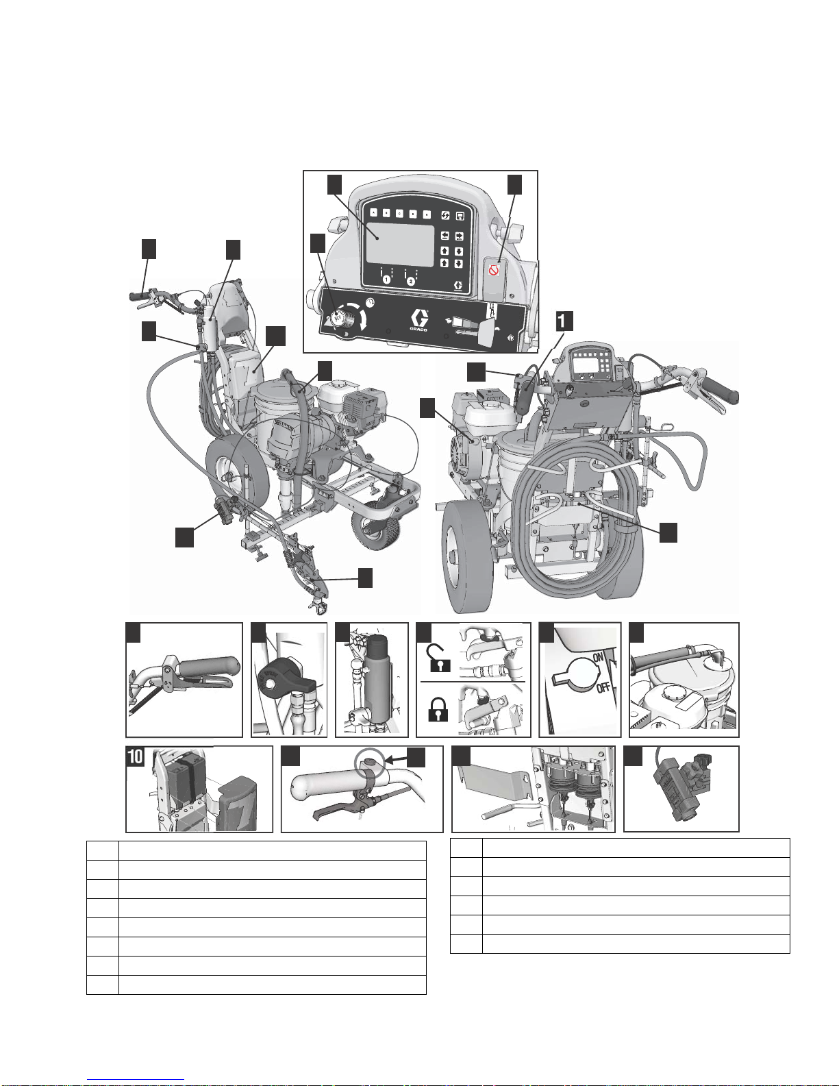
Component Identification (LLV 3900/5900)
1 Display
2 Pump ON/OFF switch & Engine Stop switch
3 Pressure control
4 Manual spray gun trigger
5 Prime/Pressure relief valve
6 Filter
7 Trigger safety
8 Engine ON/OFF switch
9 Drain and siphon tubes
*10 12 volt battery
11 Turn control
*12 Gun actuators
*13 Layout laser
*14 Auto spray gun control button
*HP Auto Series only. Upgrade to HP Auto Series with
P/N 25A527.
10 3A3388A Operation
Page 11
Grounding Procedure (For Flammable Materials Only)
ti27607a
ti27608a
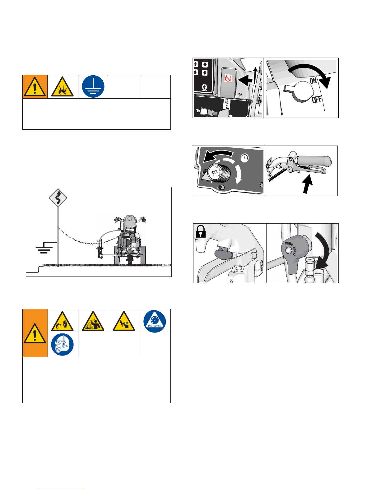
Grounding Procedure
(For Flammable Materials Only)
This equipment must be grounded to reduce the risk
of static sparking. Static sparking can cause fumes to
ignite or explode. Grounding provides a n escape wire
for the electric current.
1. Position striper so that the tires are not on pavement.
2. Striper is shipped with a grounding clamp. Grounding clamp must attach to grounded object (e.g.
metal sign post).
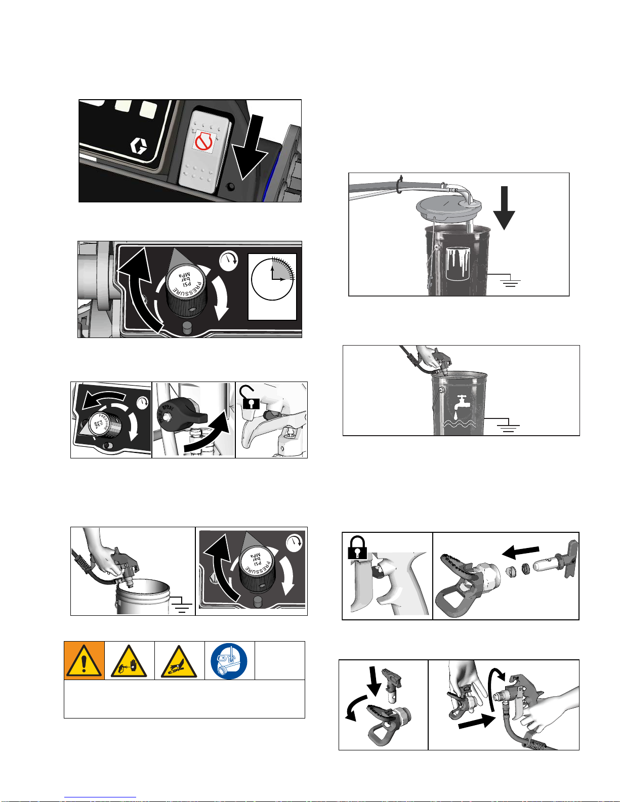
2. Set pump switch to OFF. Turn engine OFF.
ti27504a
3. Turn pressure control to lowest setting. Trigger all
guns to relieve pressure.
4. Engage all gun trigger locks. Turn prime valve
down.
v
ti27615a
Pressure Relief Procedure
This equipment stays pressurized until pressure is
manually relieved. To help prevent serious injury
from pressurized fluid, such as skin injection, splashing fluid and moving parts, follow the Pressure Re lief
Procedure when you stop dispensing and before
cleaning, checking, or servicing the equipment.
1. Perform Grounding Procedure if using flammable
materials.
5. If you suspect the spray tip or hose is clogged or
that pressure has not been fully relieved:
a. VERY SLOWLY loosen the tip guard retaining
nut or the hose end coupling to relieve pressu re
gradually.
b. Loosen the nut or coupling completely.
c. Clear the obstruction in the hose or tip.
3A3388A Operation 11
Page 12
Setup/Startup
ti3307a
ti27610a
ti27611a
Pic 001
(same as pg.10)
ti27612a
Setup/Startup
This equipment stays pressurized until pressure is
manually relieved. To help prevent serious injury
from pressurized fluid, such as skin injection, splashing fluid and moving parts, follow the Pressure Re lief
Procedure when you stop spraying and before cleaning, checking, or servicing the equipment.
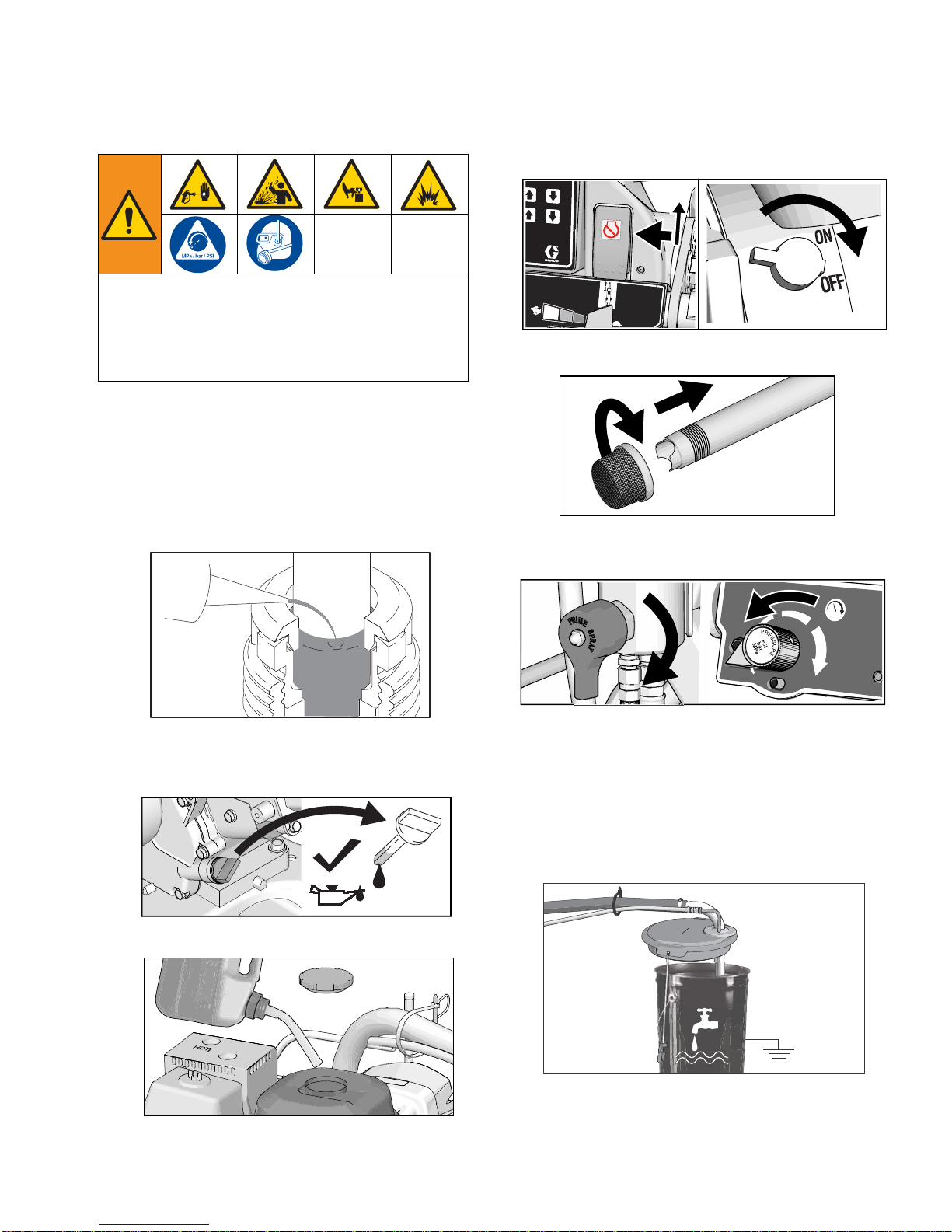
6. Set pump switch to OFF. Turn engine off.
ti27504a
7. If removed, install strainer.
1. Perform
Pressure Relief Procedure
, page 11
.
2. Perform Grounding Procedure (For Flammable
Materials Only), page 11, if using flammable mate-
rials.
3. Fill throat packing nut with Throat Seal Liquid (TSL)
to decrease packing wear.
4. Check engine oil level. Add SAE 10W-30 (summer)
or 5W-30 (winter). See engine manual.
8. Turn prime valve down. Turn pressure con tr ol coun terclockwise to lowest pressure.
ti27614a
NOTE: Minimum hose size allowable for proper
sprayer operation is 3/8 in. x 50 ft for LL3900/5900.
9. Place siphon tube set in grounded metal pail partially filled with flushing fluid. Attach ground wire to
true earth ground. Use water to flush water-base
paint and mineral spirits to flush oil-base paint and
storage oil.
5. Fill fuel tank.
12 3A3388A Operation
ti27613a
Page 13
Setup/Startup
ti27616a
ti27617a
ti27618a
ti27618a
ti27619a
ti27620a
ti27618a
ti27767a
ti27833a
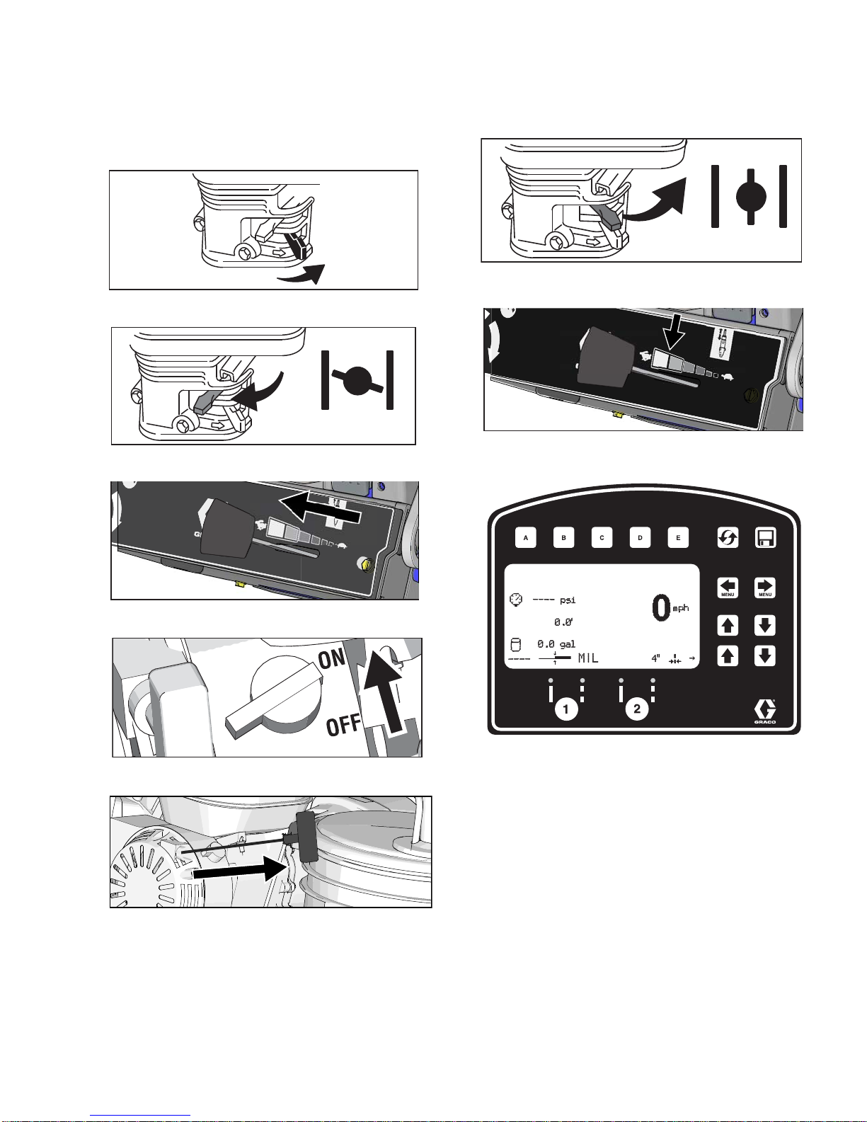
10. Start engine:
a. Move fuel valve to open.
b. Move choke to closed.
c. Set throttle to fast.
11. After engine starts, move choke to open.
ti27766a
12. Set throttle to desired setting.
13. Digital display is functional after engine starts.
d. Set engine switch to ON.
e. Pull starter cord.
3A3388A Operation 13
Page 14
Setup/Startup
ti27770a
15s
ti27771a
ti27772a
ti27775a
ti27776a
14. Set pump switch to ON (pump is now active).
ti27769a
15. Increase pressure control enough to start pump.
Allow fluid to circulate for 15 seconds.
16. Turn pressure down, turn prime valve hor izon ta l .
Disengage gun trigger lock.
18. Inspect fittings for leaks. If leaks occur, turn spraye r
OFF immediately. Perform Pressure Relief Proce-
dure. Tighten leaky fittings. Repeat Setup/Startup,
steps 1 - 17. If no leaks, continue to trigger gun until
system is thoroughly flushed. Proceed to step 18.
19. Place siphon tube in paint pails.
ti27613a
20. Trigger all guns again into a flushing fluid pail until
paint appears. Assemble tips and guards.
17. Hold all guns against a grounded metal flushing pail.
Trigger guns and increase fluid pressure slowly u ntil
pump runs smoothly.
High-pressure spray is able to inject toxins into the
body and cause serious bodily injury. Do not stop
leaks with hand or rag.
ti27774a
SwitchTip and Guard Assembly
1. Engage trigger lock. Use end of SwitchTip to press
OneSeal into tip guard, with curve matching tip
bore.
2. Insert SwitchTip in tip bore and firmly thread assembly onto gun.
14 3A3388A Operation
Page 15
Gun Placement
ti27777a
ti27778a
ti28129a
ti28130a
1
2
ti27781a
ti27782a
ti27782a
Gun Placement
Install Guns
1. Insert guns into gun holder. Tighten clamps.
Position Gun
2. Position gun: up/down, forward/reverse, left/right.
See Gun Positions Chart, page 17 for examples.
Another option can be to swing the gun out at an angle
and rotate the tip guard. This results in better visibility
for the user.
Select Guns (Standard Series)
3. Connect gun cables to left or right gun selector
plates.
ti27780a
a. One gun: Disconnect one gun selector plate
from trigger.
NOTE: When striping above a curb, the mounting clamp
can be rotated for clearance.
b. Both guns simultaneously: Adjust both gun
selector plates to the same position.
c. Solid-skip and skip-solid: Adjust solid-line gun
to position 1 and skip-line to position 2.
3A3388A Operation 15
Page 16

Gun Placement
1s
ti27784a
ti27881a
ti27785a
Gun
1
Gun
2
Gun
1
Gun
2
Gun
1
Gun
2
Gun
1
Gun
2
Select Auto Guns (HP Auto Series)
1. Use the gun selector buttons to determine which
guns are active. Each gun selector has 3 settings:
continuous line, OFF and programmed line pattern.
2. Use the gun trigger control to actuate auto guns.
4 Examples:
16 3A3388A Operation
Page 17
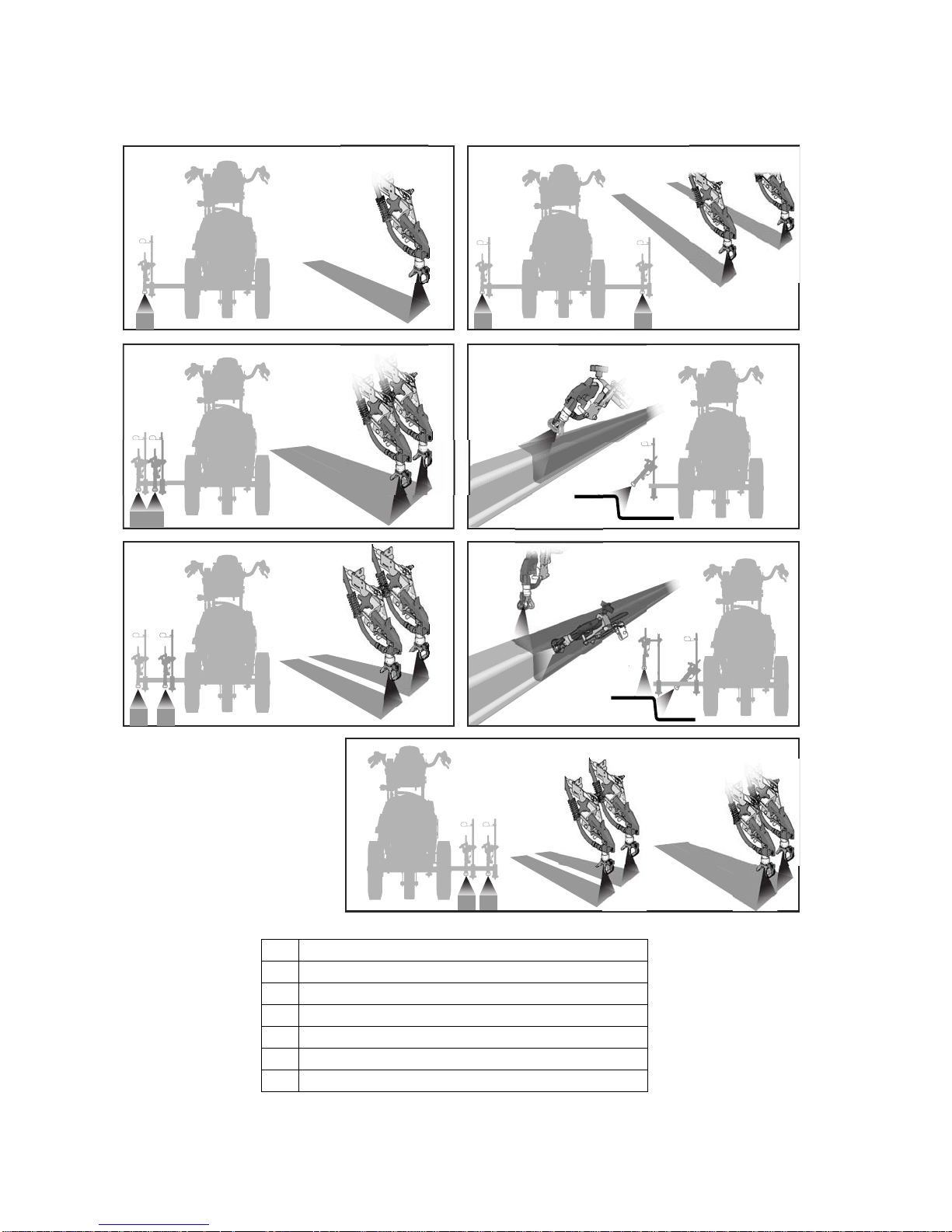
Gun Positions Chart
1
2
3
4
5
6
7
ti27786a
Gun Placement
1 One line
2 One line up to 24 in. (61cm) wide
3 Two lines
4 One line or two lines to spray around obstacles
5 One gun curb
6 Two gun curb
3A3388A Operation 17
7 Two lines or one line up to 24 in. (61 cm) wide
Page 18
Gun Placement
ti27794a
ti27795a
ti27797a
ti27798a
ti27799a
ti27919a
ti27800a
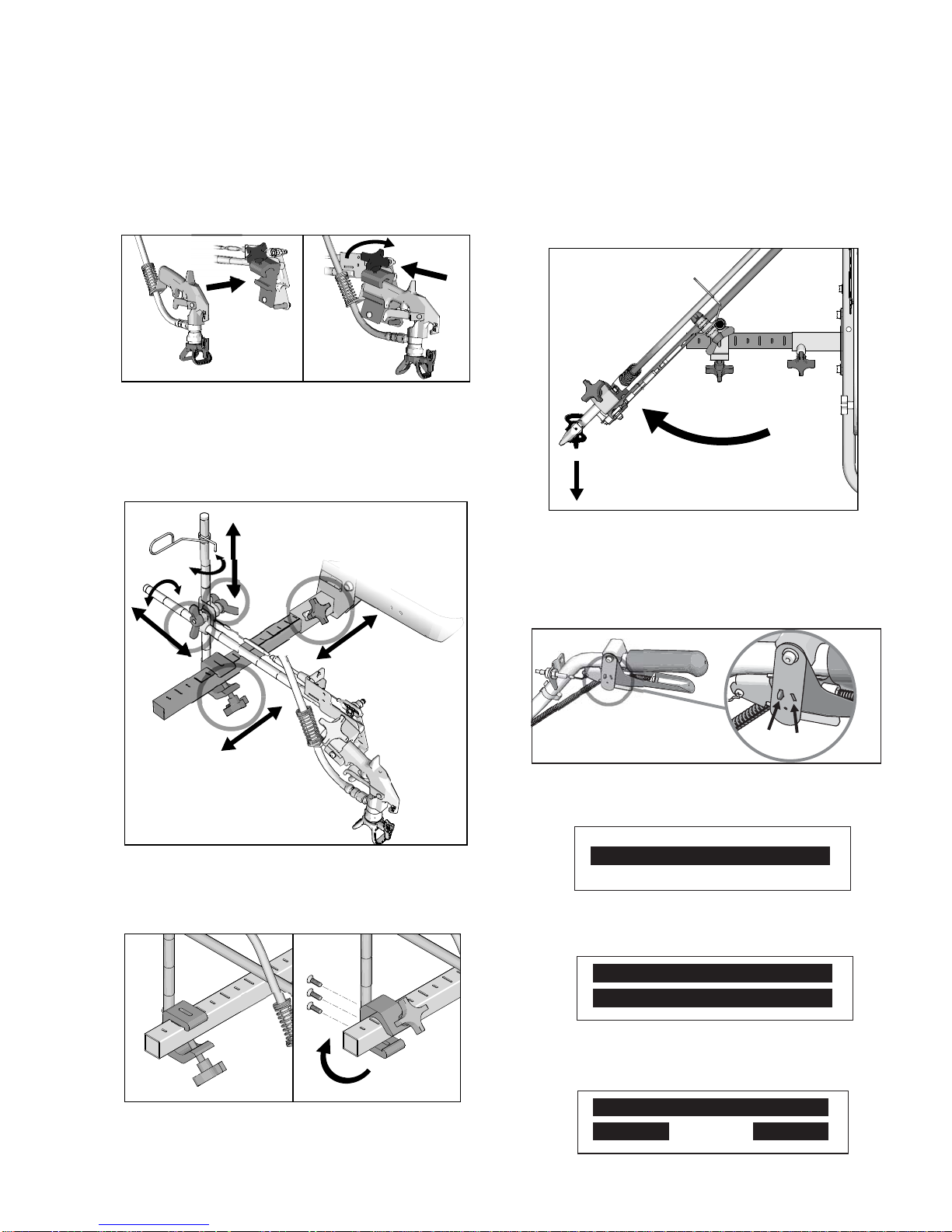
Gun Arm Mounts
This unit is equipped with front and rear gun arm
mounts.
Change Gun Position
4. Tighten gun arm knob into gun arm mounting slot.
NOTICE
Make sure all hoses, cables, and wires are properly
routed through brackets and do NOT rub on tire.
Contact with tire will result in damaged hoses, cables,
and wires.
Change Gun Position
(Left and Right)
Removal
1. Loosen vertical gun arm knob on gun arm mounting
bar and remove.
(Front and Back)
1. Loosen gun arm knob and remove from gun arm
mounting slot.
ti27796a
2. Slide gun arm assembly (including gun and hoses)
out from gun arm mounting slot.
3. Slide gun arm assembly into desired gun arm
mounting slot.
2. Extend mounting bar on opposite side of the
machine.
18 3A3388A Operation
Page 19
Gun Placement
ti27801a
30.8
0.0
9
1490
mph
0
6
˝
mph
0
6
˝
ti27940a
30.8
0.0
9
1490
Standard Series
HP Auto Series
ti27883a
Installation
1. Install vertical gun mount onto gun bar.
NOTE: Make sure all hoses, cables, and wires are
properly routed through brackets.
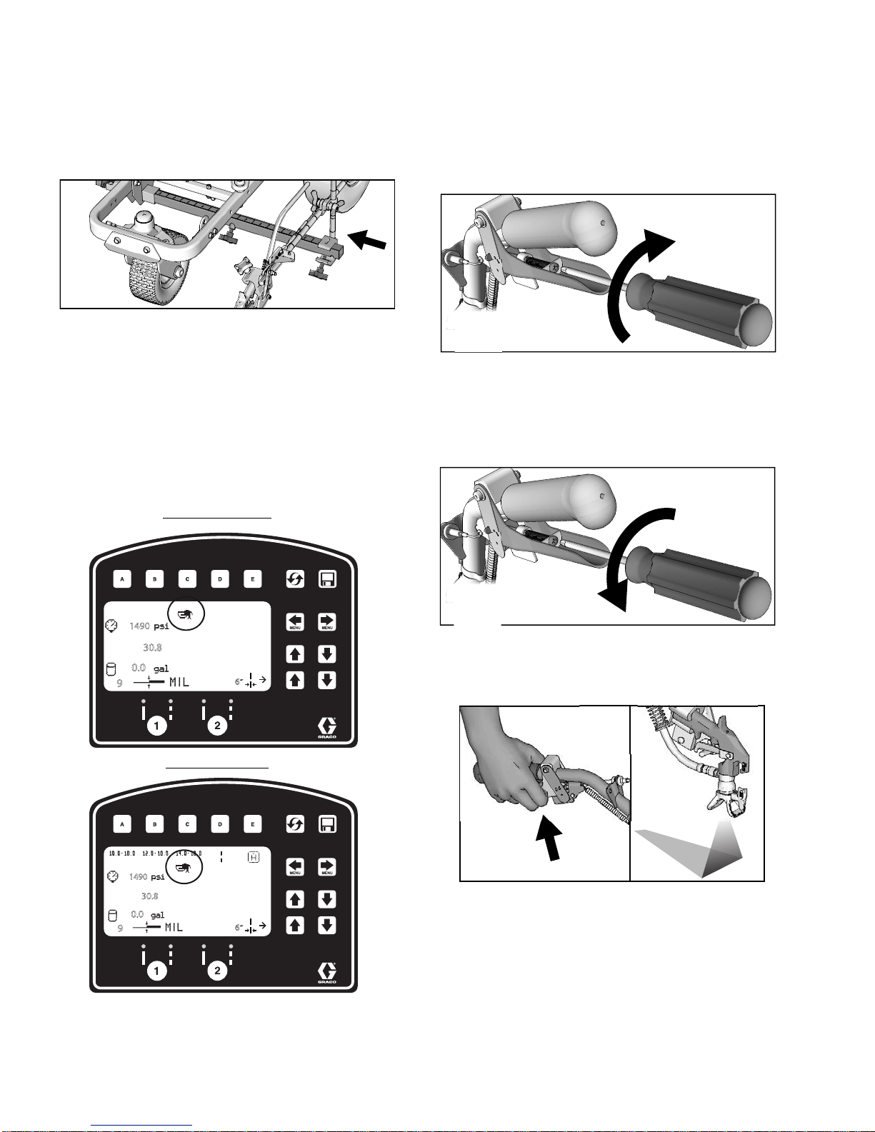
Trigger Sensor Adjustment
1. Start striper engine. Engage trigger. Spray icon
should appear simultaneously with start of fluid
spray.
No fluid spray
2. Turn screw in handle clockwise if spray icon
appears before fluid spray starts.
ti27802a
No spray icon
3. Turn screw in handle counterclockwise if fluid spray
starts before spray icon appears.
ti27803a
4. Continue adjusting screw in handle until timing of
spray icon and fluid spray are synchronized. Adjustment of the gun cables might be necessary.
3A3388A Operation 19
Page 20
Gun Placement
Standard Series
HP Auto Series
ti27804a
ti27805a
ti27806a
ti27807a
ti27809a
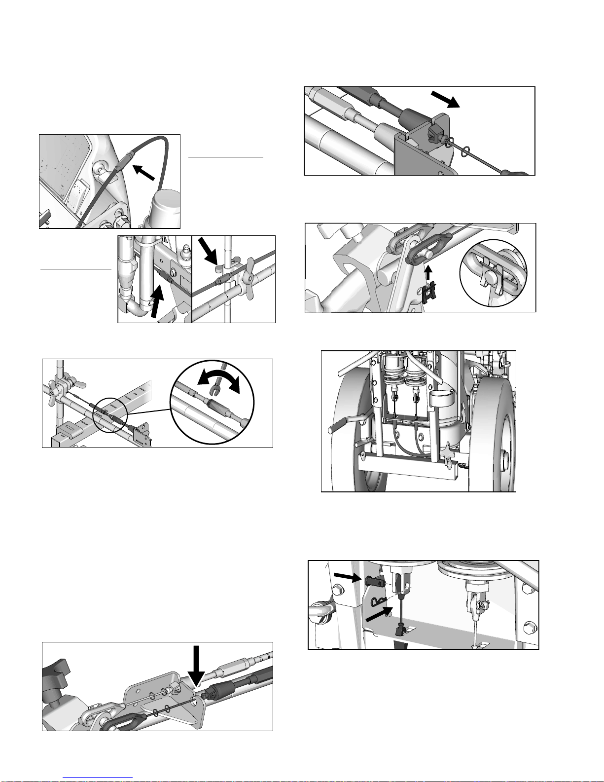
Gun Cable Adjustment
Adjusting the gun cable will increase or decrease the
gap between the trigger plate and the gun trigger. To
adjust trigger gap, perform the steps below.
ti27884a
ti27885a
1. Use wrench to loosen locking nut on cable adjuster.
3. Insert plastic cable retainer into cable bracket hole.
4. Install cable end onto trigger plate pin and install
clip.
5. Route cable around unit and up through cable holes
behind hose mount.
2. Loosen or tighten adjuster until desired result is
achieved. NOTE: More thread exposed means less
gap between gun trigger and trigger plate.
3. Use wrench to tighten locking nut on the adjuster.
Adding Gun Cable (HP Auto Series)
The HP Auto Series can be equipped with two gun actuators. Each gun actuator is capable of operating one
cable.
1. Select cable end with adjuster.
2. Install exposed cable through cable bracket slot.
ti27808a
6. Route cable end loop through rectangular hole in
bracket and insert plastic cable retainer into the
actuator bracket. Install cable end onto actuator rod
and install pin.
20 3A3388A Operation
Page 21

Gun Placement
ti27810a
ti27811a
ti27812a
ti27813a
ti27814a
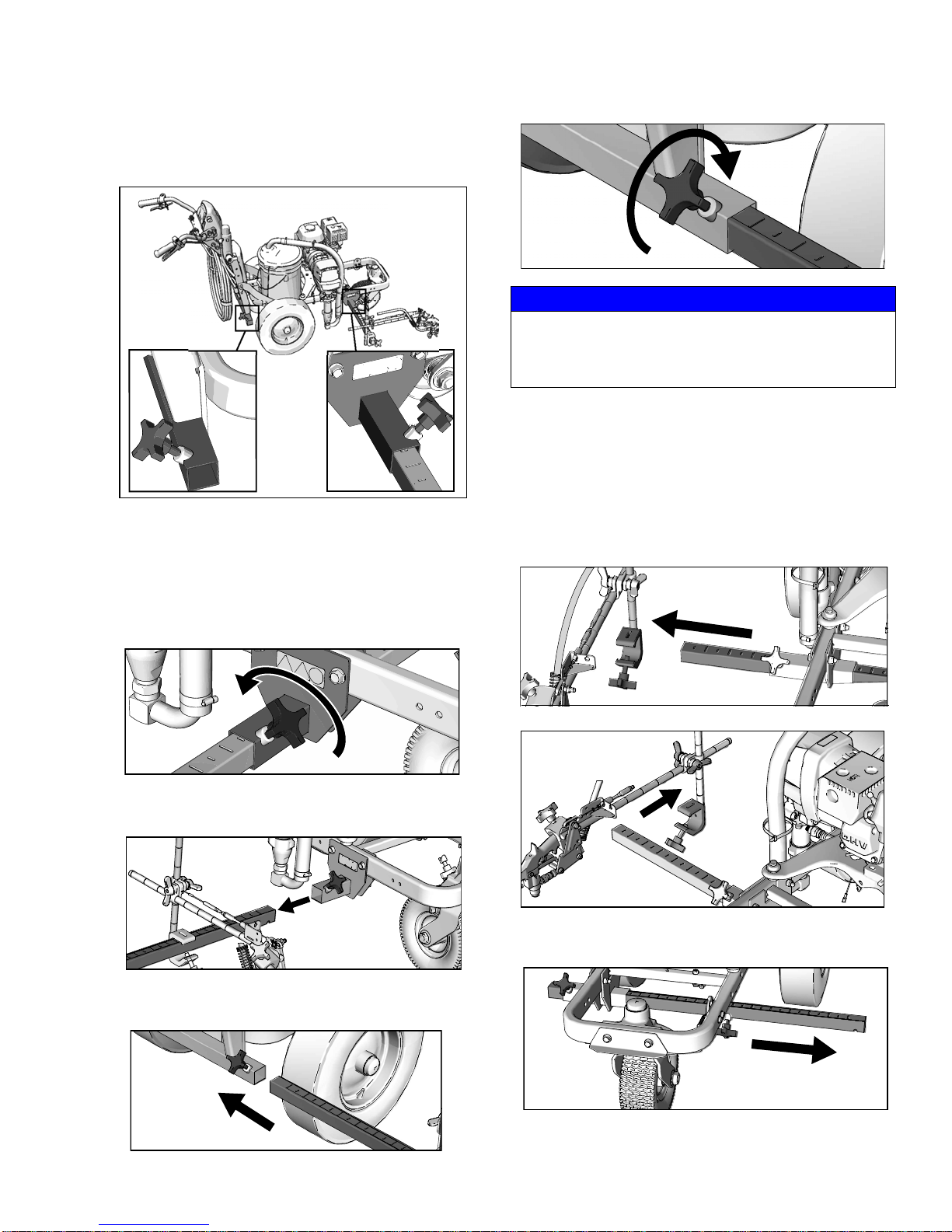
Straight Line Adjustment
The front wheel is set to center the unit and allow the
operator to form straight lines. Over time, the wheel may
become misaligned and will need to be readjusted. To
re-center the front wheel, perform the following steps:
1. Loosen bolt on the front wheel bracket.
2. If striper arcs to the right, loosen left set screw and
tighten right set screw for fine tune adjustment.
4. Roll the striper. Repeat steps 2 and 3 until striper
rolls straight. Tighten bolt on wheel alignment plate
to lock the new wheel setting.
Handle Bar Adjustment
3. If striper arcs to the left, loosen right set screw and
tighten left set screw.
3A3388A Operation 21
Page 22

Gun Placement
ti27886a
ti27815a
ti27816a
ti27887a
ti27888a
ti27817a
Dot Laser (if applicable)
LASER LIGHT HAZARD. Avoid direct eye contact.
1. Remove battery cover.
2. Attach ON/OFF switch to desired location on the
handle bar.
4. Route wires from the switch to the battery and connect to the (+) and (-) terminals.
ti27818a
5. Connect the switch leads to the wire harness.
6. Reattach battery cover.
3. Attach laser to desired location on the gun arm.
22 3A3388A Operation
7. Turn on laser and position dot underneath gun
head.
Page 23

Cleanup
TI3371A
ti6269a
ti3322b
This equipment stays pressurized until pressure is
manually relieved. To help prevent serious injury
from pressurized fluid, such as skin injection, splashing fluid and moving parts, follow the Pressure Re lief
Procedure when you stop dispensing and before
cleaning, checking, or servicing the equipment.
1. Perform Pressure Relief Procedure, page 11.
2. Remove guard and SwitchTip from all guns.
Cleanup
4. Clean filter, guard and SwitchTip in flushing fluid.
TI3375A
FLUSH
5. Place siphon tube set in grounded metal pail partially filled with flushing fluid. Attach ground wire to
true earth ground. Perform Startup steps 10 - 17
(see page 13) to flush out paint in sprayer. Use
water to flush water-base paint and mineral spirits
solvent (also called white spirit) to flush oil-base
paint.
3. Unscrew cap, remove filter. Assemble without filter.
6. Hold gun against paint bucket and pull trigger until
water or solvent appears.
7. Move gun to solvent or water bucket. Hold gun
against bucket and pull trigger until the system is
thoroughly flushed.
8. Fill pump with Pump Armor and reassemble filter,
guard and SwitchTip.
9. Each time you spray and store, fill throat packing
nut with TSL to decrease packing wear.
3A3388A Operation 23
Page 24

Standard Series
ti27920a
Standard Series
24 3A3388A Operation
Page 25

LineLazer V LiveLook Display
STRIPING SCREEN
s Displays:
s$ISTANCEOFSPRAYEDLINE
s'ALLONS0UMPED
s*OB-ILAND,IVE-IL
s3PEED
s0RESSURE
s)NPUT,INE7IDTH
s4AKEUPTOMEASUREMENTS
BYPRESSINGTHEBUTTONTO
STARTTHEMEASUREMENTAND
PRESSINGITAGAINTOEND
THEMEASUREMENT
s3ETTINGSANDINFORMATIONCAN
BEACCESSEDFROMTHISSCREEN
s
&ORACCURATEDISTANCECALCULATIONS
THEMACHINEMUSTBECALIBRATED
0RESSTOCALIBRATETHEMACHINE
5SEADISTANCEOFATLEASTFEET
ORMORE
MEASURE MODE SETTING/INFO
MEASURE MODE
1950 psi
746¹
46 gal
14 mil
CALIBRATIONa
B
C
D
ENG
SETTINGS
INFORMATION
SPA FRE GLOBAL
I/0
0.00
¹
0.00
¹
0.00
¹
0.00
¹
0.00
¹
0.00
¹
mph
0
6
É
TIA
a
a
a
SELECTION BUTTONS
RESET...
Distance, Gallons, Job Mil
JOB LOGGING
Only active with HP Auto
Series. Upgrade with P/N
25A527.
CYCLE THROUGH
MENU SCREENS
ADJUSTMENT
ARROWS
AUTO-GUN CONTROL BUTTONS
Only active with HP Auto Series. Upgrade with P/N 25A527.
1950 psi
746
¹
46 gal
14 MIL
mph
0
6
É
ti27819a
Standard Series
LineLazer V LiveLook Display
3A3388A Operation 25
Page 26

LineLazer V LiveLook Display
ti27827a
ti27828a
26 Ft.
8M
ti27829a
Initial Setup (Standard Series)
The initial setup prepares the striper for opera tion based
on a number of user entered parameters. Language
selections and the units of measure selections can be
set before you start or changed later.
Language
From Setup/Information select appropriate language by
pressing until the language is outlined.
US Units
Pressure = psi
Volume = gallons
Distance = feet
Line Thickness = mil
SI Units
Pressure = bar (MPa available)
Volume = liters
Distance = meters
2
Line thickness = micron (g/m
available)
Paint Specific Gravity = Use UP and DOWN arrows
to set specific gravity. Required to determine paint
thickness.
NOTE: All units can be changed individually at any
time.
Calibration
1. Check rear tire pressure 55 ± 5 psi (379 ± 34 kpa)
and fill if necessary.
2. Extend steel tape to distance greater than 26 ft.
(8m).
ENG = English
SPA = Spanish
FRE = French
DEU = German
RUS = Russian
WORLD = Symbols see World Symbol Key, page
59.
NOTE: Language can be changed later.
Units
Press to enter settings and then again to enter
units. Select appropriate units of measure.
26 3A3388A Operation
Page 27

LineLazer V LiveLook Display
ti27827a
ti27830a
1 FT 2 FT 3 FT 4 FT 5 FT 6 F
ti27831a
26 FT 27 FT 28 FT 29 FT 30 FT 31 F25 FT
ti27832a
3. Press to select Setup/Information.
4. Press for Calibration. Set TRAVEL DIST to 25 ft
(7.6m) or longer. Longer distances ensure better
accuracy, depending on conditions.
\
6. Push to start calibration.
ti27826a
7. Move striper forward. Keep unit aligned with steel
tape.
8. Stop when chosen part of unit aligns with 26-ft (8m),
or distance entered, on steel tape (25-ft./ 7.6m distance).
5. Align part of the unit with 1 foot (30.5cm) on steel
tape.
9. Push to complete calibration.
ti27941a
• Calibration is not complete when the exclamation
symbol is displayed.
• Calibration is finished when the check mark symbol
is displayed.
10. Calibration is now complete.
Go to Measure Mode (Standard Series), page 29, and
verify accuracy by measuring the tape.
3A3388A Operation 27
Page 28

LineLazer V LiveLook Display
5
1 2
3
4
9
8
7
6
ti27889a
MIL
ti27890a
Striping Mode (Standard Series)
Ref. Description
1 Resets Distance, Gallons, Mils
*2 Job logging
3 Scroll between menu screens
4 Line width adjustment buttons
*5 Auto gun buttons
6 MIL thickness. While spraying “Instant MIL avg” is
displayed. When stopped total “Job MIL avg” is
displayed.
7 Total gallons sprayed
8 Total line length sprayed.
9 Pressure
* Not active in Standard Series. Upgrade to HP Auto
Series with P/N 25A527.
Operating in Striping Mode
1. Make sure engine is running.
2. Set pump switch to ON.
ti27769a
3. Pull trigger to spray.
28 3A3388A Operation
Page 29

LineLazer V LiveLook Display
3
4
Measure Mode (Standard Series)
Measure Mode replaces a tape measure to measure
distances when laying out an area to be striped.
1. Use to select Measure Mode.
1 2
ti27834a
2. Press and release . Move striper forwards or
backwards. (Moving backwards is a negative distance.)
ti27902a
3. Press and release to end measured length. Up
to six lengths are viewable.
Ref. Description
1 Press to start measurement, Press to stop
measurement
2 Hold to reset values to zero
3 Scroll between main menu screens
4 Last measurement taken
ti27911a
3A3388A Operation 29
Page 30

LineLazer V LiveLook Display
ti27835a
Setup/Information
Use to select Setup/Information.
Press to select Language.
See Language, page 26.
See Calibration, page 26.
See Settings, page 31.
See Information, page 32
30 3A3388A Operation
Page 31

Settings
ti27839a
Use to select Setup/Information. Press to
open Settings Menu.
LineLazer V LiveLook Display
Chooses the machine type. Necessary for accurate
gallon counting.
Use
to set time and date.
Use
Set units with
Use to adjust screen contrast to the desired
value.
3A3388A Operation 31
Page 32

LineLazer V LiveLook Display
ti27836a
Stroke Counter
Pressure Transducer
Distance Sensor
Touch Pad Buttons
Engine Voltage
Battery Voltage
Information
Use to select Setup/Information. Press to
open Information Menu.
Displays and logs life data and striper information.
View and test functionality of components.
Logs last four error codes that occurred.
Code Description
02 = Over pressure
03 = No transducer detected
Reset error codes
32 3A3388A Operation
Page 33

HP Auto Series
ti27942a
HP Auto Series
3A3388A Operation 33
Page 34

LineLazer V LiveLook Display
STRIPING SCREEN MEASURE MODE LAYOUT MODE SETTING/INFO
MEASURE MODE
1950 psi
10- 40 5-20
15- 30
746¹
46 GAL
14 MIL
10.0¹
30.0¹
I/0
0.00
¹
0.00
¹
0.00
¹
0.00
¹
0.00
¹
0.00
¹
mph
ti27879a
9.00 10. 00 11. 0 0
sMain striping screen. -UST
BEINTHISMODETOELECTRONICALLY
ACTUATEGUNS
s!UTOMATIC3KIP#YCLESCANBE
LAIDFROMTHISSCREEN#HOOSE
SKIPLINEONTHEDESIREDGUNTO
FIRE%NTERTHE0AINTAND3PACE
DISTANCEWANTEDANDBEGIN
SPRAYING
s0RESSTHE%"UTTONTOCHOOSE
HOWTHEREDBUTTONACTUATES
THEGUNS
M(OLDTOSPRAYRELEASETOSTOP
S
0RESSFORONETIMESHOTWHEN
IN3KIP-ODE
A 0RESSTOSTARTPRESSTOSTOP
sMeasure Mode. !BILITYTOTAKE
UPTOMEASUREMENTSBY
PRESSINGTHEREDBUTTONTOSTART
THEMEASUREMENTANDPRESSINGIT
AGAINTOENDTHEMEASUREMENT
s)FAN!UTO'UNISSELECTEDSEE
BELOWANDTHEREDBUTTONIS
HELDDOWNADOTWILLBEDROPPED
EVERYvUNTILTHEREDBUTTONIS
RELEASED
sLayout Mode. $ROPADOTATA
CHOSENDISTANCETOLAYOUTA
PARKINGLOT
s%NTERSTALLSIZEACTIVATEANAUTO
GUNPRESSTHEREDBUTTONAND
ROLLTHEMACHINE4OSTOP
DOTTINGPRESSTHEREDBUTTON
AGAIN&AVORITESCANBESAVED
JUSTLIKEINTHEMAINSCREEN
SEEPAGE
SEEPAGE
s3ETTINGSAND)NFORMATIONCANBE
ACCESSEDFROMTHISSCREEN
s&ORACCURATEDISTANCECALCULA-
TIONSTHEMACHINEMUSTBE
CALIBRATED0RESS!TOCALIBRATE
THEMACHINE5SEADISTANCEOF
ATLEASTORMORE
ti27845a
TOGGLE BETWEEN SKIP CYCLE
AND LINE WIDTH DISPLAY ON SCREEN
SKIP LINE PRESETS AND SELECTION BUTTON
s4OSAVEFAVORITEPRESETSENTERTHE0AINTAND3PACE
LENGTHSDESIREDWITH!DJUSTMENT!RROWS4HENPRESS
ANDHOLD!"OR#TO
ENTERTHATVALUEINTOFAVORITE
4HESEWORKJUSTLIKE&AVORITESONACARRADIO
AUTO-GUN CONTROL BUTTONS.
s0RESSTOCHOOSESOLIDLINE0RESSTOTURNOFF(OLDFORSECONDTOCHOOSE3KIP,INE
CHOOSE BETWEEN HOW THE RED
BUTTON ACTUATES THE GUN
M
(OLDTHEBUTTONTOSPRAYRELEASETOSTOP-ANUAL
S
0RESSFORONETIMESHOTWHENIN3KIP-ODE
A
0RESSTHEBUTTONTOSPRAY0RESSAGAINTOSTOP!UTO
RESET -
$ISTANCE'ALLONS*OB-IL
3TART.EW*OB
JOB LOGGING
CYCLE THROUGH
MENU SCREEN
ADJUSTMENT
ARROWS
TIA
LineLazer V LiveLook Display
HP Auto Series
34 3A3388A Operation
Page 35

LineLazer V LiveLook Display
ti27827a
ti27828a
26 Ft.
8M
ti27829a
Initial Setup (HP Auto Series)
The initial setup prepares the striper for opera tion based
on a number of user entered parameters. Language
selections and the units of measure selections can be
set before you start or changed later.
Language
From Setup/Information select appropriate language by
pressing until the language is outlined.
US Units
Pressure = psi
Volume = gallons
Distance = feet
Line Thickness = mil
SI Units
Pressure = bar (MPa available)
Volume = liters
Distance = meters
2
Line thickness = micron (g/m
available)
Paint Specific Gravity = Use UP and DOWN arrows
to set specific gravity. Required to determine paint
thickness.
NOTE: All units can be changed individually at any
time.
Calibration
1. Check rear tire pressure 55 ± 5 psi (379 ± 34 kpa)
and fill if necessary.
2. Extend steel tape to distance greater than 26 ft.
(8m).
ENG = English
SPA = Spanish
FRE = French
DEU = German
RUS = Russian
WORLD = Symbols see World Symbol Key, page
59.
NOTE: Language can be changed later.
Units
Press to enter settings and then again to enter
units. Select appropriate units of measure.
3A3388A Operation 35
Page 36

LineLazer V LiveLook Display
ti27827a
ti27830a
ti27841a
ti27912a
ti27843a
ti27912a
3. Press to select Setup/Information.
4. Press for Calibration. Set TRAVEL DIST to 25 ft
(7.6m) or longer. Longer distances ensure better
accuracy, depending on conditions.
6. Press and release gun trigger control to start calibration.
7. Move striper forward. Keep laser dot on steel tape.
8. Stop when laser aligns with 26-ft (8m) or distance
entered on steel tape (25-ft./7.6m distance).
5. Turn on laser and align laser dot with 1 foot
(30.5cm) on steel tape.
9. Press and release gun trigger control to complete
calibration.
• Calibration is not complete when the exclamation
symbol is displayed.
• Calibration is finished when the check mark symbol
is displayed.
10. Calibration is now complete.
36 3A3388A Operation
Page 37

Striping Mode (HP Auto Series)
1
12
11
10
9
2 345
6
7
8
ti27844a
1450 psi
30.8¹
0.0 gal
9 MIL
ti27881a
LineLazer V LiveLook Display
Ref. Description
Select a “Favorite”, press for less than one sec-
ond.
1
Save a “Favorite”, press and hold for more than
three seconds.
2 Cycles between viewing line width or paint and
space value.
Cycles between Manual Mode, Semi-Automatic
Mode, Automatic Mode.
Manual Mode : Press and hold gun trigger
control to stripe.
Semi-Automatic Mode : Press and release
3
gun trigger control to stripe the programmed
length one time when in Skip Mode.
Automatic Mode : Press and release gun
trigger control to start striping. Press and release
button again to stop.
4 Resets values and starts recording a new job.
5 Job Data Logger, page 47.
6 Scrolls between menu screens.
7 Paint and Space length OR line width adjustment
buttons.
8 Auto guns activation buttons.
9 MIL thickness. While spraying “Instant MIL avg” is
displayed. When stopped total “Job MIL avg” is
displayed.
10 Total gallons (liters) sprayed.
11 Total line length sprayed.
12 Pressure
Operating in Striping Mode
Striper must be running before activating gun trigger
control.
1. Make sure engine is running.
2. Use gun activation buttons to select guns and line
type.
ti27913a
3. Press gun trigger control to begin spraying.
In Automatic Mode or Semi-Automatic Mode the or
will flash when gun trigger control is pressed to sig-
nal mode is active.
3A3388A Operation 37
Page 38

LineLazer V LiveLook Display
ti27914a
2 3
5
4
1
ti27842a
ti27842a
Measure Mode (HP Auto Series)
Measure Mode replaces a tape measure to measure
distances when laying out an area to be striped.
1. Use to select Measure Mode.
2. Press and release gun trigger control. Move striper
forwards or backwards. (Moving backwards is a
negative distance.)
3. Press and release gun trigger control to end measured length. Up to six lengths are viewable.
The most recent measured length is also saved as the
measured distance in the Stall Calculator display. See
Stall Calculator, page 40.
If an auto gun is activated, press and hold gun trigger
control at any time to apply a dot. If trigger is held while
striper is moving, a dot is marked every 12-inches
(30.5cm).
Ref. Description
1 Press to start measurement, Press to stop
measurement.
2 Hold to reset values to zero.
3 Job Data Logger, page 47.
4 Scroll between main menu screens
5 Last measurement taken
v
ti27915a
38 3A3388A Operation
Page 39

LineLazer V LiveLook Display
192 34
5
6
7
8
ti27916a
ti27918a
ti27849a
Layout Mode
Layout Mode is used to calculate and mark parking lot
stalls.
1. Use to select Layout Mode.
Ref. Description
2. Use gun activation buttons to select guns.
3. Press and release gun trigger control and move
striper forward.
ti27912a
4. Striper default is to place a dot every 9.0 ft (2.7m) to
mark the stall size. Stall size is adjustable.
5. Dots are laid down until gun trigger control is
pressed and released again.
1 Opens Stall Calculator Menu.
See Stall Calculator, page 40.
2 Opens Angle Calculator Menu.
See Angle Calculator, page 41.
Select a “Favorite”, press for less than one sec-
3
ond.
Save a “Favorite”, press and hold for more than
three seconds.
4 Job Data Logging, page 47.
5 Scroll between menu screens.
6 Adjust stall size/dot spacing.
7 Adjust dot size.
8 Auto Gun activation buttons.
9 Pressure.
An indicator on the screen alternately flash when gun
trigger control is pressed to signal mode is active.
3A3388A Operation 39
Page 40

LineLazer V LiveLook Display
1 2
6
5
4
3
7
ti27848a
8
ti27917a
90.00’
9.00’
10.00’
10.00’
Stall Calculator
Stall Calculator is used to set the stall size. The striper
divides the measured length by the stall size to determine the number of stalls that will fit in the length measured. User can adjust number of stalls to a round
number and stall width is calculated.
1. Use to select Layout Mode. Press to
open Stall Calculator Menu.
2. The most recent length measured in Measure Mode
is automatically displayed. Press gun trigger control
to start a new measurement. Press again to stop
measuring.
Stall size and calculated number of stalls are both
adjustable.
3. Press to return to Layout Mode. The Stall size
is saved and displayed on the Layout Mode screen.
Ref. Description
1 Opens Angle Calculator Menu.
See Angle Calculator, page 41.
2 Exits and returns stall size to Layout Mode.
3 Measured distance.
4 Calculated # of stalls. Changing the number of
stalls will change the stall size.
5 Adjusts numbe r of stalls.
6 Stall size. Changing stall size changes the calcu-
lated # of stalls.
7 Adjusts stall size.
8 Press to start measurement, Press to stop mea-
surement.
40 3A3388A Operation
4. Press and release gun trigger control to start marking dots. Press and release gun trigger control again
to stop.
Page 41

LineLazer V LiveLook Display
7
8
5
6
STALL
SIZE
LINE
LENGTH
B
C
STALL
DEPTH
OFF SET
ANGLE
DOT SPACING
B
A
OFF SET
Angle Calculator
Angle Calculator is used to determine the offset value
and dot spacing value for a layout.
1. Use to select Layout Mode. Press to
open Angle Calculator Menu.
1
2 3 4
ti27850a
2. Dot spacing (B) and offset (C) are calculated based
on the parameters entered:
Stall angle
Stall depth
Stall size (width)
Line Length
ti27857a
3. Press
to transfer calculated off set distance to
Layout Mode. Save this value in favorites if desired.
Ref. Description
1 Transfers calculated dot spacing, B, to Layout
Mode.
2 Transfers calculated off set, C, to Layout Mode.
3 Exits and returns to Layout Mode without transfer-
ring any values.
4 Data Logging.
5 Select input variables.
6 Adjust the variable selected.
7 Calculated dot spacing, B.
8 Calculated off set, C.
ti28024a
3A3388A Operation 41
Page 42

LineLazer V LiveLook Display
B
A
ti27842a
4. Press to transfer calculated dot spacing distance to Layout Mode. Save this value in favorites if
desired.
5. Press and release gun trigger control to start marking stall size dots. Press and release gun trigger
control to stop marking.
ti27856a
42 3A3388A Operation
Page 43

Setup/Information
ti27858a
Use to select Setup/Information.
LineLazer V LiveLook Display
Press to select Language.
See Language, page 35.
See Calibration, page 35.
See Settings, page 44.
See Information, page 45.
See Marker Layout Mode, page 46.
3A3388A Operation 43
Page 44

LineLazer V LiveLook Display
ti27859a
Settings
Use to select Setup/Information. Press to
open Settings Menu.
Chooses the machine type. Necessary for accurate gallon
counting.
Use
to set time and date. Needed for accurate Data Logging.
Set units with
Use to adjust screen contrast to the desired value.
For programmed skip lines, press to choose:
Paint first
or
Space first
44 3A3388A Operation
ti28158a
In Auto-mode, guns won’t fire or will shut off if speed is below set
value.
Enable or Disable Low Speed Shutoff
Adjust low speed setting.
Page 45

Information
ti27836a
Stroke Counter
Pressure Transducer
Distance Sensor
Touch Pad Buttons
Engine Voltage
Battery Voltage
Clutch
Solenoid 1
Solenoid 2
Battery charger state
Use to select Setup/Information. Press to
open Information Menu.
LineLazer V LiveLook Display
Displays and logs life data and striper information.
View and test functionality of component
Logs last four error codes that occurred.
Code Description
02 = Over pressure
03 = No transducer detected
3A3388A Operation 45
Reset error codes
Page 46

LineLazer V LiveLook Display
3
4
ti27862a
[1] 8.00´
[2] 4.00´
[3] 4.00´
[4] 16.00´
[5] 4.00´
[6] 4.00´
[7] 8.00´
[8] 0.00´
8.00 ft. 8.00 ft.
4.00 ft.
4.00 ft.
16.00 ft.
48.00 ft.
4.00 ft.4.00 ft.
ti23812a
Marker Layout Mode
The Marker Layout Mode feature sprays a dot or a
series of dots to mark an area.
1. Use to select Setup/Information. Press
to open Marker Layout Mode.
1
1
Ref. Description
Select a “Favorite”, press for less than one sec-
ond.
1
Save a “Favorite”, press and hold for more than
three seconds.
2 Exits and returns to Information Menu.
3 Select value to change.
4 Adjust spacing value.
2
ti27860a
4. Set gun switch to skip line or solid line.
ti27918a
5. Press and release gun trigger control to start marking dots. Press and release gun trigger control again
to stop.
ti27912a
An indicator before and after Marker Mode on the
screen alternately flash when gun trigger control is
pressed to signal mode is active.
2. Use arrow keys to set up a marker pattern.
3. Marker layout example shows a typical lane layout
for reflective markers. Set space sizes up to eight
consecutive measurements. By leaving zeros in any
space, Marker Layout Mode will skip to the next
measurement in a continuous loop.
Some other uses of Marker Layout Mode are:
• Multiple spaced handicap stall layout
• Double line stalls
46 3A3388A Operation
Page 47

Data Logging
ti28063a
LINE STCL TOT
AL
jO
XX
XX
XX
XX
XX
XX
XX
XXXX
START RECORDING NEW JOB
VIEW J-LOG
ERASE J-LOG
TIME STAMP
EXIT
A
B
C
E
0001 26.12.2015 1:00 300 12 1.1 0.0 1.1
0001 26.12.2015 2:00 100 14 0.7 2.0 2.7
0001 26.12.2015 3:00 400 15 3.0 1.0 4.5
0002 26.12.2015 5:00 0 15 0.0 4.0 4.0
0002 26.12.2015 6:00 1100 14 3.9 1.0 4.9
0002 26.12.2015 7:00 100 14 0.3 0.0 0.3
0003 26.12.2015 9:30 700 15 2.3 0.5 2.8
0003 26.12.2015 10:00 1200 12 4.1 1.0 5.1
JOB DATE TIME feet mil
â
LineLazer V LiveLook Display
The LLV control is equipped with Data Logging, which
allows the user to recall job data.
1. Press the to open the Data Logging pop up
window.
2. Choose to start recording a new job, view the J-Log,
erase the J-Log, or take a time stamp.
3. On the main striping screen, if the user resets the
data with a new job is automatically started.
Start recording a new job.
Erase the entire J-Log
User requested time stamp for the J-Log.
Gallons/liters of line painted
J-Log is a constant data recorder that will take a time
stamp and show the data since the previous time
stamp. Time stamps occur at the following intervals:
• Every time the machine is turned on
• Every hour of constant run time
• When the user manually takes a time stamp
• When line width changes and paint is spra ye d
• When a new job is started
Gallons/liters of stencil painted
Total gallons/liters
When the J-Log is 90% full, the user will be notified. If the
J-Log is 100% full, Data Logging stops until the user
clears the J-Log.
3A3388A Operation 47
Page 48

Maintenance
Maintenance
LineLazer V 3900, 5900
Periodic Maintenance
DAILY: Check engine oil level and fill as necessary.
DAILY: Check hose for wear and damage.
DAILY: Check gun safety for proper operation.
DAILY: Check pressure drain valve for prop er ope r a-
tion.
DAILY: Check and fill gas tank.
DAILY: Verify calibration.
AFTER THE FIRST 20 HOURS OF OPERATION: Drain
engine oil and refill with clean oil. Reference Honda
Engines Owner’s Manual for correct oil viscosity.
WEEKLY: Remove air filter cover and clean element.
Replace element, if necessary. If operating in an unusually dusty environment: check filter daily and replace, if
necessary.
Caster Wheel
1. Once each year, tighten nut under dust cap until
spring washer bottoms out, then back off the nut 1/2
to 3/4 turn.
2. Once each month, grease the wheel bearing.
3. Check pin for wear. If pin is worn out, there will be
play in the caster wheel. Reverse or replace the pin
as needed.
4. Check caster wheel alignment as necessary. To
align; page 21.
Replacement elements can be purchased from your
local HONDA dealer.
WEEKLY: Check level of TSL in displacement pump
packing nut. Fill nut, if necessary. Keep TSL in nut to
help prevent fluid buildup on piston rod and premature
wear of packings.
AFTER EACH 100 HOURS OF OPERATION: Change
engine oil. Reference Honda Engines Owner’s Manual
for correct oil viscosity.
SPARK PLUG: Use only BPR6ES (NGK) or
W20EPR-U (NIPPONDENSO) plug. Gap plug to 0.028
to 0.031 in. (0.7 to 0.8 mm). Use spark plug wrench
when installing and removing plug.
48 3A3388A Operation
Page 49

Troubleshooting
Problem Cause Solution
Engine won’t start Engine switch is OFF. Turn engine switch ON.
Engine is out of gas. Refill gas tank. Honda Engines Owner’s Man-
ual.
Engine oil level is low Try to start engine. Replenish oil, if necessary.
Honda Engine Owner’s Manual.
Engine operates, but displacement pump does not
operate.
Spark plug cable is disconnected or damaged.
Cold engine. Use choke.
Fuel shutoff lever is OFF. Move lever to ON position.
Oil is seeping into combustion chamber. Remove spark plug. Pull starter 3 to 4 times.
Error code displayed? Reference error codes. Page 32.
Pump switch is OFF. Turn pump switch ON.
Pressure setting is too low. Turn pressure adjusting knob clockwise to
Fluid filter is dirty. Clean filter. Page 23.
Tip or tip filter is clogged. Clean tip or tip filter. See spray gun manual.
Displacement pump piston rod is stuck due to
dried paint.
Connecting rod is worn or damaged. Replace connecting rod.
Drive housing is worn or damaged. Replace drive housing.
Electrical power is not energizing clutch field. Check wiring connections. Page 58.
Clutch is worn, damaged, or incorrectly positioned.
Pinion assembly is worn or damaged. Repair or replace pinion assembly.
Connect spark plug cable or replace spark plug.
Clean or replace spark plug. Start engine. Keep
sprayer upright to avoid oil seepage.
increase pressure.
Repair pump. See pump manual.
Reference wiring diagram. Page 58.
With pump switch ON and pressure turned to
MAXIMUM, use a test light to check for power
between clutch test points on control board.
Disconnect clutch wires from control board and
measure resistance across clutch coil. At 70° F,
the resistance must be between 1.2+0.2 ohms
(LineLazer V 3900); 1.7+0.2 ohms (LineLazer
5900); if not, replace pinion housing.
Have pressure control checked by authorized
Graco dealer.
Replace clutch. Page 55.
Troubleshooting
3A3388A Operation 49
Page 50

Troubleshooting
Problem Cause Solution
Pump output is low. Strainer is clogged. Clean strainer.
Piston ball is not seating. Service pisto n ball. See pump manual.
Piston packings are worn or damaged. Replace packings. See pump manual.
O-ring in pump is worn or damaged. Replace o-ring. See pump manual.
Intake valve ball is not seating properly. Clean intake valve. See pump manual.
Intake valve ball is packed with material. Clean intake valve. See pump manual.
Engine speed is too low. Increase throttle setting. See operation manual.
Clutch is worn or damaged. Replace clutch. Page 55.
Pressure setting is too low. Increase pressure. See operation manual.
Fluid filter (11), tip filter or tip is clogged or
dirty.
Large pressure drop in hose with hea vy mate -
rials.
Excessive paint leakage
Throat packing nut is loose. Remove throat packing nut spacer. Tighten
into throat packing nut.
Throat packings are worn or damaged. Replace packings. See pump manual.
Displacement rod is worn or damaged. Replace rod. See pump manual.
Fluid is spitting from gun. Air in pump or hose. Check and tighten all fluid connections. Reprime
Tip is partially clogged. Clear tip. See spray gun manual.
Fluid supply is low or empty. Refill fluid supply. Prime pump. See operation
Pump is difficult to prime. Air in pump or hose. Check and tighten all fluid connections.
Intake valve is leaking. Clean intake valve. Be sure ball seat is not
Pump packings are worn. Replace pump packings. See pump manual.
Paint is too thick. Thin the paint according to supplier’s recom-
Engine speed is too high. Decrease throttle setting before priming pump.
Clutch squeaks each time
clutch engages.
High engine speed at no
load.
Clutch surfaces are not matches to each other
when new and may cause noise.
Mis-adjusted throttle setting. Reset throttle to 3600 engine rpm at no load.
Worn engine governor. Replace or service engine governor.
Clean filter. See operation or spray gun manual.
Use larger diameter hose and/or reduce overall
length of hose. Use of more than 100 ft of 1/4 in.
hose significantly reduces performance of
sprayer. Use 3/8 in. hose for optimum performance (50 ft. minimum).
throat packing nut just enough to stop leakage.
pump. See Operation manual.
manual. Check fluid supply often to prevent running pump dry.
Reduce engine speed cycle pump as slowly as
possible during priming.
nicked or worn and that ball seats well. Reassemble valve.
mendations.
See operation manual.
Clutch surfaces need to wear into each other.
Noise will dissipate after a day of run time.
50 3A3388A Operation
Page 51

Problem Cause Solution
Troubleshooting
Gallon (liter) counter not
adding fluid volume.
Sprayer operates, but display does not.
Distance not adding properly (Measure mode will be
inaccurate and speed will be
wrong).
Mils not calculating or calculates wrong.
Fluid spray starts after spray
icon is shown on display.
Spray icon does not show on
display when fluid is
sprayed.
Spray icon is always shown
on display.
Fluid pressure not high enough. Must be over 800 psi (55 bar) for counter to add.
Broken or disconnected pump counter wire,
both pumps.
Check wires and connections. Replace any broken wires
Missing or damaged magnet. Reposition or replace magnet on pump, see
Parts manual (Pump parts) for magnet location.
Bad sensor, both pumps. Replace sensor.
Bad connection between control board and
Remove display and reconnect.
display.
Display damaged. Replace display.
Machine not calibrated. Perform calibration procedure. See Operation
manual.
Rear tire pressure is too low or too high. Adjust tire pressure to 55 +/- 5 psi (380 +/-
34kPa).
Gear teeth missing or damaged (right side
Replace distance gear/wheel hub.
when standing on platform).
Distance sensor is loose or broken. Reconnect or replace sensor.
Distance sensor. See “Distance counter not operating properly”.
Gallon counter. See “Gallon (liter) counter not adding fluid vol-
ume.”
Line width not entered. Set line width on main striping screen.
Bad or damaged control board. Replace control board.
Interrupter. Turn screw counterclockwise until spray icon
synchronizes with fluid spray, page 19.
Loose connector. Check connector and reconnect.
Interrupter is improperly positioned.
Turn screw counterclockwise until spray icon
synchronizes with fluid spray, page 19.
Reed switch assembly is damaged.
Replace reed switch assembly.
Magnet on assembly is missing. Replace reed switch assembly.
Cut or sliced wire. Replace distance sensor harness.
Control board is damaged. Replace control board.
Display is damaged. Replace display.
Interrupter is improperly positioned.
Turn screw clockwise until spray icon is synchro-
nized with fluid spray, page 19.
Reed switch assembly is damaged.
Replace reed switch assembly.
3A3388A Operation 51
Page 52

Troubleshooting
Problem Cause Solution
AUTO GUN MODE
Auto Gun won’t actuate
when the red button is
pressed.
Line Spacing is not accurate
Battery won’t stay
charged.
Auto Gun won’t shut off
Gun is not activated. Press the 1 or 2 button on control to activate a
gun.
Cable is not adjusted properly. Adjust Cable to properly actuate gun trigger,
page 20.
Not on main striping screen. Go to main striping screen on control to Actuate
Auto Guns.
Low Speed Shut off is enabled. Disable Low Speed Shutoff, see page 43.
Battery Voltage is too low. Check battery voltage on Diagnostic Screen,
page 32, or with Volt meter. If below 11.5V,
charge battery or replace battery.
Cable is not adjusted properly. Adjust Cable to properly actuate gun trigger,
page 20.
Red button is broken. Test button functionality in Diagnostic screen.
page 32, replace if broken.
Auto Gun Cable is broken or extremely kinked
resulting in too much drag.
Solenoid wire is disconnected or broke. Check Wiring Diagram,
Fuse to battery is removed or blown. Check and replace fuse.
Solenoid is jammed. S pray Lubrication on solenoid plunger.
Solenoid is failed. Check resistance across solenoid wires. Resis-
Control board is failed. Replace Control board.
Wrong line pattern loaded. Reload the correct pattern.
Machine is out of calibration. Calibrate the machine, page 35.
Accessories are left on and drain the battery
when unit is not running.
Throttle is not set high enough. Make sure engine is being ran above 3300 rpm
Power consumption from accessories is higher
than engine output.
Wiring is broken or disconnected. Check Wiring Diagram, page 58, repair or
Charger is not working. Check Charging state in diagnostics, page 32, to
Cable is kinked. Repair or replace cable.
Solenoid is jammed. Lubricate solenoid plunger, Check for solenoid
Needle in gun is clogged. Clean out gun.
Replace Auto Gun Cable.
page 58, repair or
replace wires if necessary.
tance should be between .2 and .26 ohms. If it’s
not, replace solenoid.
Turn off accessories when machine is not in use.
NO LOAD for proper power supply.
Reduce accessories or charge battery when nec-
essary.
replace wires if necessary.
see if charger is properly working. Replace
Board.
damage.
52 3A3388A Operation
Page 53

Problem Cause Solution
LAYOUT MODE
No dots or poor dots in
Layout and Marking
Mode.
Troubleshooting
Too small of Dot setting. Increase Dot size, page 39.
Gun is not activated. Press the 1 or 2 button on control to activate a
gun.
Cable is not adjusted properly. Adjust Cable to properly actuate gun trigger,
page 20.
Tip clog. Clear tip or Replace tip.
Battery voltage is too low. Charge battery or replace battery.
Pump is not on, or pressure is not set. Turn on pump and increase pressure to a mini-
mum of 200 psi.
3A3388A Operation 53
Page 54

Troubleshooting
With a pressure gauge plumbed into the paint
hose, start the engine. Turn pump switch ON.
Does sprayer exceed maximum pressure?
Pump or Pressure Relief valve problem.
See the proper fluid pump manual for the
sprayer for further troubleshooting procedures.
Disconnect clutch wires from control board (see
diagram, page 58). Does the pump stop ru nning?
Mechanical problem in the clutch pinion assembly (clutch may be too close to the rotor).
Make sure clutch wires are plugged in (see diagram, page 58). Do the clutch test points read
10-18 DC volts?
Check for a short from the two clutch wires
to the frame. If shorted, repair or replace
faulty wire.
Unplug transducer from control board. Does
the pump stop running?
Bad transducer.
Replace and test with a new one.
Replace the control board.
YES
NO
YES
YES
YES
NO
NO
NO
Fluid Pump Runs Constantly
Troubleshooting Procedure:
1. Perform Pressure Relief Procedure, page 11, turn
prime valve forward to SPRAY position, and turn
power switch OFF.
2. Remove control box over.
54 3A3388A Operation
Page 55

Pinion Assembly/Clutch Armature/Clamp
36
37
36
37
29
ti5480a
19
E
28
24
ti5481a
ti5987b
E
29
29b
29a
ti5482a
27
29d
TIA
Pinion Assembly/Clutch Armature/Clamp
Pinion Assembly/Clutch Armature Removal
Pinion Assembly
If pinion assembly (29) is not removed from clutch housing (19), do 1. through 3. Otherwise, start at 4.
1. Remove drive housing.
2. Disconnect clutch cable connectors from inside of
pressure control.
a. Remove two screws (71) and swing down cover
(130a).
b. Disconnect engine leads from board to engine.
c. Remove strain reliefs 130r and 123.
3. Remove four screws (36) and pinion assembly (29).
6. Remove retaining ring (29b).
7. Turn pinion assembly over and tap pinion s haft
(29a) out with plastic mallet.
Clutch Armature
8. Use an impact wrench or wedge something
between clutch armature (25) and clutch housing to
hold engine shaft during removal.
4. Place pinion assembly (29) on bench with rotor side
up.
5. Remove four screws (28) and lock washers (24).
Install two screws in threaded holes (E) in rotor.
Alternately tighten screws until rotor comes off.
3A3388A Operation 55
9. Remove four screws (23) and lock washers (24).
10. Remove armature.
Page 56

Pinion Assembly/Clutch Armature/Clamp
0.12+01 in (3.0+.25 mm)
25
26
dimes
ti6321a
ti6199a
"
!
TIA
19
4
3
2
1
Face of clutch housing
1.550 ± .010 in. (39.37 ± .25 mm) - LLV 3900
2.612 ± .010 in. (66.34 ± .25 mm) - LLV 5900
Torque to 125 ±.10 in-lb (14 ±1.1 N•m)
Chamfer this side
Installation
Clutch Armature
1. Lay two stacks of two dimes on smooth bench surface.
2. Lay armature (25) on two stacks of dimes.
3. Press center of hub (26) down to bench surface.
4. Install armature (25) on engine drive shaft.
5. Install four screws (23) and lock washers (24) with
torque of 125 in-lb.
Pinion Assembly
1. Check o-ring (29d) and replace if missing or damaged.
2. Tap pinion shaft (29a) in with plastic mallet.
3. Install retaining ring (29b) with beveled side facing
up.
4. Place pinion assembly on bench with rotor side up.
4. Loosen two screws (24) on clamp (22),
5. Push screwdriver into slot in clamp (22) and remove
clamp.
Clamp Installation
1. Install engine shaft key (18).
2. Tap clamp (22) onto engine shaft (A). Maintain
dimension shown note 2. Chamfer must face
engine.
3. Check dimension: Place rigid, straight steel bar (B)
across face of clutch housing (19). Use accurate
measuring device to measure distance between bar
and face of clamp. Adjust clamp as necessary.
Torque two screws (24) to 125 ±10 in-lb (14 ±1.1
N•m).
5. Apply thread sealant to screws. Install four screws
(28) and lock washers (24). Alternately torque
screws to 125 in-lb until rotor is secure. Use
threaded holes to hold rotor.
6. Install pinion assembly (29) with four screws (36)
and washers (37).
7. Connect clutch cable connectors to inside of pressure control.
Clamp Removal
1. Remove engine.
2. Drain gasoline from tank according to Honda manual.
3. Tip engine on side so gas tank is down and air
cleaner is up.
56 3A3388A Operation
Page 57

Wiring Diagram (Standard Series)
196
44
YELLOW
GREY
23
CLUTCH COIL
(119512)
96
45
46
YELLOW
WHITE/YELLOW
RED
WHITE/RED
169
CLUTCH/ENGINE
STOP SWITCH
(128783)
148
141
POTENTIOMETER
58
CONTROL BOARD
(24Y310 - STANDARD)
BLACK
WHITE
BLACK
RED
PROGRAMMING PORT
ti28147a
Wiring Diagram (Standard Series)
3A3388A Operation 57
Page 58

Wiring Diagram (HP Auto Series)
-
+
196
44
YELLOW
GREY
23
RED
BLACK
CLUTCH COIL
(119512)
96
45
46
YELLOW
WHITE/YELLOW
RED
WHITE/RED
169
CLUTCH/ENGINE
STOP SWITCH
(128783)
148
141
POTENTIOMETER
58
CONTROL BOARD
(24Y311 - HP AUTO)
BLACK
WHITE
BLACK
RED
PROGRAMMING PORT
GUN 1
GUN 2
BLACK
RED
CHARGER BOARD
(24Y443 - HP AUTO)
30A AUTOMOTIVE FUSE
REGULAR ATO
FUSE HOLDER
205
214
ti28062a
Wiring Diagram (HP Auto Series)
58 3A3388A Operation
Page 59

World Symbol Key
World Symbol Key
MENU SCREENS
STRIPING MODE MEASURE MODE
LAYOUT MODE SETTINGS/DATA
DATA LOGGING
MANUAL,
SEMI- AUTOMATIC or
AUTOMATIC MODE
PRESSURE
GALLONS/LITERS
LINE THICKNESS
PAINT LENGTH
SPACE LENGTH
LINE WIDTH
EXIT
YELLOW
PRESS TO START/STOP
HOLD TO SPRAY A DOT
STALL CALCULATOR
ANGLE CALCULATOR
STALL WIDTH
DOT SIZE SELECTOR
CALIBRATE START RECORDING
NEW JOB
JOBS
TIME STAMP
SCROLL
SETTINGS
UNITS
INFORMATION
& LIFE DATA
MARKER LAYOUT MODE
GUN SETTINGS
SPECIFIC GRAVITY
ENGINE HOURS
TOTAL DISTANCE
TOTAL GALLONS
SOFTWARE REV
ERROR CODES
CONTRAST
DIAGNOSTICS
TIME AND DATE
LOW SPEED SHUTOFF
I/O
....
....
ș
÷
x
+
÷
x
+
-
1 2 3 4 5 6 7 8 9 10
TOTALGALLONS/
LITERS
X'
X'
A
TIME AND DATE
S
WHITE
BLUE
GREEN
RED
BATTERY LOW
BLACK
BATTERY CHARGING
DELETE
DISTANCE PAINTED
GALLONS OF LINE
PAINTED
X
GALLONS OF
STENCIL PAINTED
World Symbol Key
ti28025a
LLV GLOBAL SYMBOL KEY
3A3388A Operation 59
Page 60

Technical Specifications
Technical Specifications
LineLazer V 3900 Standard Series (Models 17H449, 17H450)
U.S. Metric
Dimensions
Height
Width
Length
Weight (dry - no paint)
Noise (dBa)
Sound Power per ISO 3744:
Sound Pressure measured at 3.3 feet (1m):
Vibration (m/s2) (8 hours daily exposure)
Hand Arm (per ISO 5349)
Whole Body (per ISO 2631)
Power Rating (Horse Power)
Power Rating (Horse Power) per SAE J1349 4.0 HP @ 3600 rpm 2.9 kW @ 3600 rpm
Maximum Delivery 1.25 gpm 4.7 lpm
Maximum Tip Size
1 gun
2 gun
Inlet paint strainer 16 mesh 1190 micron
Outlet paint strainer 50 mesh 297 micron
Pump inlet size 1 in. NSPM (m)
Pump outlet size 3/8 NPT (f)
Maximum working pressure 3300 psi 228 bar, 22.8 MPa
Electrical Capacity 50 W@ 3600 rpm
Battery (optional) 12V, 22Ah, Sealed lead acid, Deep cycle
Unpackaged - 44.5 in.
Packaged - 52.5 in.
Unpackaged - 34.25 in.
Packaged - 37.0 in.
Unpackaged - 68.75 in.
Packaged - 73.5 in.
Unpackaged - 230 lbs
Packaged - 297 lbs
Unpackaged - 113.03 cm
Packaged - 133.35 cm
Unpackaged - 86.99 cm
Packaged - 93.98 cm
Unpackaged - 174.63 cm
Packaged - 186.69 cm
Unpackaged - 104 kg
Packaged - 135 kg
103.1
86.5
1.6
0.4
.036
.025
Wetted Parts: PTFE, Nylon, polyurethane, V-Max,
UHMWPE, fluoroelastomer, acetal, leather, tungsten
carbide, stainless steel, chrome plating, nickel-plated
carbon steel, ceramic
60 3A3388A Operation
Page 61

Technical Specifications
LineLazer V 5900 Standard Series (Models 17H454, 17H455)
U.S. Metric
Dimensions
Height (with handle bar down)
Width
Length (with platform down)
Weight (dry - no paint)
Noise (dBa)
Sound Power per ISO 3744:
Sound Pressure measured at 3.3 feet (1m):
Vibration (m/s2) (8 hours daily exposure)
Hand Arm (per ISO 5349)
Whole Body (per ISO 2631)
Power Rating (Horse Power)
Power Rating (Horse Power) per SAE J1349 5.5 HP @ 3600 rpm 4.1 kW @ 3600 rpm
Maximum Delivery 1.6 gpm 6.0 lpm
Maximum Tip Size
1 gun
2 gun
Inlet paint strainer 16 mesh 1190 micron
Outlet paint strainer 50 mesh 297 micron
Pump inlet size 1 in. NSPM (m)
Pump outlet size 3/8 NPT (f)
Maximum working pressure 3300 psi 228 bar, 22.8 MPa
Electrical Capacity 84 W @ 3600 rpm
Battery 12V, 22Ah, Sealed lead acid, Deep cycle
Unpackaged - 44.5 in.
Packaged - 52.5 in.
Unpackaged - 34.25 in.
Packaged - 37.0 in.
Unpackaged - 68.75 in.
Packaged - 73.50 in.
Unpackaged - 250 lbs
Packaged - 317 lbs
103.1
86.5
1.6
0.4
.043
.029
Unpackaged - 113.03 cm
Packaged - 133.35 cm
Unpackaged - 86.99 cm
Packaged - 93.98 cm
Unpackaged - 174.63 cm
Packaged - 186.69 cm
Unpackaged - 113 kg
Packaged - 144 kg
Wetted Parts: PTFE, Nylon, polyurethane, V-Max,
UHMWPE, fluoroelastomer, acetal, leather, tungsten
carbide, stainless steel, chrome plating, nickel-plated
carbon steel, ceramic
3A3388A Operation 61
Page 62

Technical Specifications
LineLazer V 3900 HP Auto Series (Models 17K577, 17H451, 17K638, 17H452, 17K579, 17H453)
U.S. Metric
Dimensions
Height (with handle bar down)
Width
Length (with platform down)
Weight (dry - no paint)
Noise (dBa)
Sound Power per ISO 3744:
Sound Pressure measured at 3.3 feet (1m):
Vibration (m/s2) (8 hours daily exposure)
Hand Arm (per ISO 5349)
Whole Body (per ISO 2631)
Power Rating (Horse Power)
Power Rating (Horse Power) per SAE J1349 4.0 HP @ 3600 rpm 2.9 kW @ 3600 rpm
Maximum Delivery 1.25 gpm 4.7 lpm
Maximum Tip Size
1 gun
2 gun
Inlet paint strainer 16 mesh 1190 micron
Outlet paint strainer 50 mesh 297 micron
Pump inlet size 1 in. NSPM (m)
Pump outlet size 3/8 NPT (f)
Maximum working pressure 3300 psi 228 bar, 22.8 MPa
Electrical Capacity 50 W @ 3600 rpm
Starting Battery 12V, 22Ah, Sealed lead acid, Deep cycle
Unpackaged - 44.5 in.
Packaged - 52.5 in.
Unpackaged - 34.25 in.
Packaged - 37.0 in.
Unpackaged - 68.75 in.
Packaged - 73.50 in.
Unpackaged - 240 lbs
Packaged - 307 lbs
103.1
86.5
1.6
0.4
.036
.025
Unpackaged - 113.03 cm
Packaged - 133.35 cm
Unpackaged - 86.99 cm
Packaged - 93.98 cm
Unpackaged - 174.63 cm
Packaged - 186.69 cm
Unpackaged - 109 kg
Packaged - 139 kg
Wetted Parts: PTFE, Nylon, polyurethane, V-Max,
UHMWPE, fluoroelastomer, acetal, leather, tungsten
carbide, stainless steel, chrome plating, nickel-plated
carbon steel, ceramic
62 3A3388A Operation
Page 63

Technical Specifications
LineLazer V 5900 HP Auto Series (Models 17K580, 17H456, 17K636, 17H457, 17K581, 17H458)
U.S. Metric
Dimensions
Height (with handle bar down)
Width
Length (with platform down)
Weight (dry - no paint)
Noise (dBa)
Sound Power per ISO 3744:
Sound Pressure measured at 3.3 feet (1m):
Vibration (m/s2) (8 hours daily exposure)
Hand Arm (per ISO 5349)
Whole Body (per ISO 2631)
Power Rating (Horse Power)
Power Rating (Horse Power) per SAE J1349 5.5 HP @ 3600 rpm 4.1 kW @ 3600 rpm
Maximum Delivery 1.6 gpm 6.0 lpm
Maximum Tip Size
1 gun
2 gun
Inlet paint strainer 16 mesh 1190 micron
Outlet paint strainer 50 mesh 297 micron
Pump inlet size 1 in. NSPM (m)
Pump outlet size 3/8 NPT (f)
Maximum working pressure 3300 psi 228 bar, 22.8 MPa
Electrical Capacity 84 W @ 3600 rpm
Starting Battery 12V, 22Ah, Sealed lead acid, Deep cycle
Unpackaged - 44.5 in.
Packaged - 52.5 in.
Unpackaged - 34.25 in.
Packaged - 37.0 in.
Unpackaged - 68.75 in.
Packaged - 73.50 in.
Unpackaged - 266 lbs
Packaged - 333 lbs
103.1
86.5
1.6
0.4
.043
.029
Unpackaged - 113.03 cm
Packaged - 133.35 cm
Unpackaged - 86.99 cm
Packaged - 93.98 cm
Unpackaged - 174.63 cm
Packaged - 186.69 cm
Unpackaged - 121 kg
Packaged - 151 kg
Wetted Parts: PTFE, Nylon, polyurethane, V-Max,
UHMWPE, fluoroelastomer, acetal, leather, tungsten
carbide, stainless steel, chrome plating, nickel-plated
carbon steel, ceramic
3A3388A Operation 63
Page 64

Graco Standard Warranty
Graco warrants all equipment referenced in this document which is manufactured by Graco and bearing its name to be free from defects in
material and workmanship on the date of sale to the original purchaser for use. With the exception of any special, extended, or limited warranty
published by Graco, Graco will, for a period of twelve months from the date of sale, repair or replace any part of the equipment determined by
Graco to be defective. This warranty applies only when the equipment is installed, operated and maintained in accordance with Graco’s written
recommendations.
This warranty does not cover, and Graco shall not be liable for general wear and tear, or any malfunction, damage or wear caused by faulty
installation, misapplication, abrasion, corrosion, inadequate or improper maintenance, negligence, accident, tampering, or substitution of
non-Graco component parts. Nor shall Graco be liable for malfunction, damage or wear caused by the incompatibility of Graco equipment with
structures, accessories, equipment or materials not supplied by Graco, or the improper design, manufacture, installation, operation or
maintenance of structures, accessories, equipment or materials not supplied by Graco.
This warranty is conditioned upon the prepaid return of the equipment claimed to be defective to an authorized Graco distributor for verification of
the claimed defect. If the claimed defect is verified, Graco will repair or replace free of charge any defective parts. The equipment will be returned
to the original purchaser transportation prepaid. If inspection of the equipment does not disclose any defect in material or workmanship, repairs
will be made at a reasonable charge, which charges may include the costs of parts, labor, and transportation.
THIS WARRANTY IS EXCLUSIVE, AND IS IN LIEU OF ANY OTHER WARRANTIES, EXPRESS OR IMPLIED, INCLUDING BUT NOT
LIMITED TO WARRANTY OF MERCHANTABILITY OR WARRANTY OF FITNESS FOR A PARTICULAR PURPOSE.
Graco’s sole obligation and buyer’s sole rem edy for any breach of warranty shall be as set forth above. The buyer agrees that n o other remedy
(including, but not limited to, incidental or consequential damages for lost profits, lost sales, injury to person or property, or any other incidental or
consequential loss) shall be available. Any action for breach of warranty must be brought within two (2) years of the date of sale.
GRACO MAKES NO WARRANTY, AND DISCLAIMS ALL IMPLIED WARRANTIES OF MERCHANTABILITY AND FITNESS FOR A
PARTICULAR PURPOSE, IN CONNECTION WITH ACCESSORIES, EQUIPMENT, MATERIALS OR COMPONENTS SOLD BUT NOT
MANUFACTURED BY GRACO. These items sold, but not manufactured by Graco (such as electric motors, switches, hose, etc.), are subject to
the warranty, if any, of their manufacturer. Graco will provi de purchaser with reasonable assistance in making any claim for breach of these
warranties.
In no event will Graco be liable for indi rect, incidental, special or consequential damages resulting from Graco supplying equipment hereunder, or
the furnishing, performance, or use of any products or other goods sold hereto, whether due to a breach of contract, breach of warranty, the
negligence of Graco, or otherwise.
Graco Information
For the latest information about Graco products, visit www.graco.com .
For patent information, see www.graco.com/patents.
TO PLACE AN ORDER,
Call Graco ProStore by RAE Products today for product sales or information
1-877-275-7550 or visit us at www.RaeProStores.com
GRACO
GRACO
All written and visual data contained in this document reflects the latest product information available at the time of publication.
GRACO INC. AND SUBSIDIARIES • P.O. BOX 1441 • MINNEAPOLIS MN 55440-1441 • USA
Copyright 2016, Graco Inc. All Graco manufacturing locations are registered to ISO 9001.
By RAE Products & Chemicals
Graco reserves the right to make changes at any time without notice.
Original instructions. This manual contains English. MM 3A3388
Graco Headquarters: Minneapolis
International Offices: Belgium, China, Japan, Korea
www.graco.com
Revision A, February 2016
 Loading...