

Page 1
LC-1000 Lube System Controller
The Trabon microprocessor based LC-1000 Controller
is a multi-use solid state controller that is dedicated to
the operation and monitoring of intermittent operating series and parallel centralized lubrication systems
equipped with a cycle or pressure switch for cycle
completion feed back.
The LC-1000 monitors and schedules lubrication intervals in either time or stroke/cycle basis in values ranging from 1 to 9999. Pump may be self cycling or single
cycle type requiring a pulsed output.
Four units are available for 12 VDC, 24 VDC, 115
VAC, or 230 VAC operation. The LC-1000 is easy to
program in the fi eld using four mini push-buttons. The
programming requires no special knowledge or training
of computer language. During power down or outage,
all data is saved in EEPROM (Electrically Erasable Programming Read Only Memory). As power is restored,
counting and pump status are restored to values prior
to the loss of power.
SPECIFICATIONS
Power Supply
115 VAC + 10%, 50/60 Hz, 1 ph
230 VAC + 10%, 50/60 Hz, 1 ph
12 VDC + 10%
24 VDC + 10%
Output Loading
Main Pump Load: ..........12 VDC – 230 VAC, 50/60 Hz
10 Amp Relay Output (External Fused by User)
Fault Output Signal: ........12 VDC – 230 VAC, 50/60 Hz
1 Amp Resistive Max. (N.O.) Dry Isolated Contact
(External Fused by User)
Temperature Range
Do Not Locate unit in Direct Sunlight
Operating:: -20OC to 50OC (-4OF to 122OF)
Storage: -25OC to 60OC (-13OF to 140OF)
Enclosure
Plastic with Clear Cover, NEMA 4X, IP 66
Display
Supertwist LCD
Annotated 4 Digit
4 LED’s: PWR (GN), LUBE (YW), FAULT (RD),
CYCLE (YW)
Stroke Input
Maximum Input Rate: 10 hz (600 CPM)
Nominal 12 Volts for 12 VDC Version
Nominal 24 Volts for 24 VDC, 115 VAC, 230 VAC
Versions
Selectable for either Source or Sink Solid State
Proximity Switch or Dry Contact 10 mA Max.
Other Inputs
Cycle Switch: ........12 Volts, Dry Contact, 2.5 mA Max.
Counts Half Cycles
Programming Selection
Output ON: ...................... 1 to 9999 Seconds, Minutes,
Hours, Counts
Output OFF:..................... 1 to 9999 Seconds, Minutes,
Hours, Counts
Cycle Counter: .............................Half Counts (0 to 99)
Pump: ....................................... Steady State or Pulsed
Pulse Off Time (Prime) – 3 Seconds Fixed
Pulse On Programmable - 0 to 99 Seconds
(Pre-Lube function is not available)
Program Entry
4 Mini Push Buttons – Program, Increase, Shift, Enter
EEPROM
Electrically Erasable Programming Read Only Memory
Page 2
LC-1000 Lube System Controller
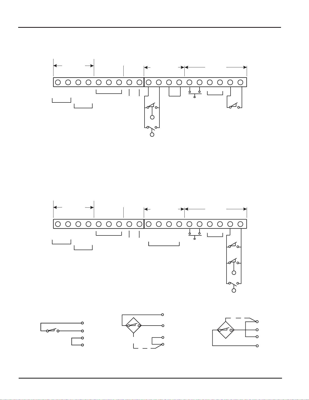
WIRING INFORMATION
Option for units built after February 1, 1999 that are programmed in time mode.
14540
INPUT
VOLTAGE
1234567
DRY
CONTACT
9
8
FIG 1
+
HOT
INPUT
-
NEU
-
+
PUMP
OUTPUT
DO NOT USE
PUMP
OPTIONAL
LOW-LEVEL SWITCH
AND/OR HIGH PRESSURE
SWITCH. BOTH MUST BE
OPEN DURING NORMAL
SYSTEM OPERATION.
CLOSURE OF SWITCH CONTACTS
CAUSES LC-1000 TO INDICATEA FAULT
CONDITION. BUT PUMP WILL CONTINUE
TO OPERATE.
FAULT
WIRING INFORMATION
All units programmed in machine count mode, or any units built prior to Februay 1, 1999.
Option for units built after February 1, 1999 that are programmed in time mode.
INPUT
VOLTAGE
1234567
FIG 2
-
+
NEU
HOT
INPUT
Figure 3, 4 and 5 refer to machine count input only.
FIG 3
DRY CONTACT SWITCH
-
+
PUMP
OUTPUT
10
10
11
11
12
12
13
13
DO NOT USE
PUMP
DRY
CONTACT
9
8
FAULT
FIG 4
SOURCE SWITCH 2 OR 3 WIRE TYPE
(SEE NOTE 1)
10
11 12 13 14 15 16
FAULT
Note 1: 12 VDC with 12 VDC Input Voltage
Note 2: Piston Distributor or Injector System will use a Pressure Switch.
(SEE NOTE 1)
10
11 12 13 14 15 16
+
SW
SW IN
FAULT
MACHINE COUNT
(SEE FIG 3 THRU 5)
CLOSURE OF SWITCH CONTACTS
CAUSES LC-1000 TO INDICATEA FAULT
CONDITION. ON EXPIRATION OF THE
NEXT ON (MONITOR) PERIOD.
SUSPENDING OPERATION OF THE PUMP.
12 VDC
18
17
JUMPER
INSTALLED
24 VDC with 24 VDC, 115 VAC and 230 VAC Input Voltage
MANUAL
RUN
DO NOT
USE
12 VDC
17
19
CYCLE
SWITCH
(SEE NOTE 2)
18
19
-
10
SENSE
SW
MANUAL
RUN
OPTIONAL
LOW-LEVEL SWITCH
AND/OR HIGH PRESSURE
SWITCH. BOTH MUST BE
OPEN DURING NORMAL
SYSTEM OPERATION.
DO NOT
USE
CYCLE
SWITCH
(SEE NOTE 2)
FIG 5
11
12
13
SINK SWITCH -
2 OR 3 WIRE TYPE
10
11
12
13
Page 2
Page 3

LC-1000 Lube System Controller
DIMENSIONS mm / (Inches)
14540
114.3
(4.50)
TIME COUNTS REMAINING
114.3
127.0
(5.00)
(4.50)
PRGM
RUN BUTTON
S
MANUAL RUN
MODEL LC-1000
MANUAL
ORDERING INFORMATION
LC-1000 Controller
VOLTAGE PART NUMBER
12 VDC 163-400-050
24 VDC 163-400-051
115 VAC, 50/60 Hz 163-400-052
230 VAC 50/60 Hz 163-400-053
Replacement Board
VOLTAGE PART NUMBER
12 VDC 572-144-644
24 VDC 572-144-645
115 VAC, 50/60 Hz 572-144-646
230 VAC 50/60 Hz 572-144-647
X
127.0
(5.00)
LUBE SYSTEM
CONTROLLER
ENTER
76.2
(3.00)
POWER
LUBE
FAULT
CYCLE
4.8 (.19)
PUSH BUTTONS:
There are four mini push buttons;
PRGM - Initiate Program mode, or alternate between
settings for:
ON (Monitor Time)
OFF (Pause Time)
CYCLE (Switch Transitions)
PUMP (Pulsed On Time)
S - Increase digit
X - Next digit select
ENTER - Enter (save) new setting and advance to
next program step.
PROGRAMMING INSTRUCTIONS
The LC-1000 Controller has icons in the display to indicate if the unit is in a lube ON cycle or OFF cycle and to
show the timing mode. They are also used to indicate
which counter is being adjusted when programming new
parameters. The LCD four digit display is used to show
the remaining time left in either an ON or OFF cycle, as
indicated by the icons. Timing can be done in seconds,
minutes, hours or counts. A fl ashing LCD character
indicates that the timer is in the Programming mode.
Page 3
Page 4

LC-1000 Lube System Controller
14540
OPERATION
When power is applied, the green “POWER LED”lights
and the LC-1000 counts down alternately from the
programmed “OFF/ON” Times/Counts to zero.
In the “ON” (Monitor) mode, the ” PUMP LED” lights.
The pump is activated and both the “ON and “RUN”
icons are displayed. If the programmed number of
cycle switch transitions (1/2 cycles) are received before expiration of the “ON” (Monitor) period, the PUMP
OUTPUT, “PUMP” LED, “ON” and “RUN” icons turn
off and the “OFF” icon will display. If the programmed
number of cycle switch transitions (1/2 cycles) are
not received before expiration of the “ON” (Monitor)
period, a “Fault” will be registered. This suspends
pump operation, turns off the ” PUMP” LED, the “ON
and “RUN” icons, turns on the red “FAULT” LED and
closes the fault output contacts.
If a pulsed output to the pump is required, a “PUMP
ON” time may be programmed from 0 to 99 seconds.
Setting this value to zero will provide a steady state
output. “PUMP OFF” is fi xed at 3 seconds.
The “RUN” icon will display anytime the pump output is energized. During pulsed pump operation, the
“RUN” icon will fl ash on and off in sequence with the
pump. During continuous running, the “RUN” icon will
not fl ash.
The Controller is programmed to retain the Time/Count
in memory when power is turned off. This feature prevents excessive lubrication in start/stop applications
and retains information for cycle to be completed when
power is restored.
CHANGING SETTINGS
From the Timer display mode, pressing the “PRGM”
button will allow you to review or change between the
set “ON” (Monitor), “OFF”, “CYCLE, “PUMP” (Pulsed
On Time) and “DISPLAY” modes. When in the programming mode, the icons/digits will blink. When in
the display mode, the icons/digits do not blink.
1. To set a new “ON” (Monitor) Time/Count, press
the “PRGM” key until the “ON” icon blinks. The
current “ON” (Monitor) Time/Count will be
displayed.
a) Press the “ENTER” key. The “ON” (Monitor)
Time/Count digit will blink.
b) Change the value using the S key and X
key.
c) Press the “ENTER” key to accept the new
value. The “SEC/MIN/HR/CNT” icon will blink
d) Press “ENTER” to accept the time base or the
S key to scroll through the timing choices.
e) Press “ENTER” to complete the process (Note:
Monitor period is normally set 2 times the
actual time required for the pump to satisfy the
system cycle requirements).
2. The “OFF” icon will now be blinking.
a) Repeat above process until all “OFF”
options have been programmed.
b) Press “ENTER” to accept the new values.
3. The “CYCLE” icon will now be blinking
a) Press “ENTER” and the cycle value
(1/2 cycles) will blink.
b) Using the S and X keys set the cycle
value as follows:
Series Progressive: ...............02 (1 divider cycle),
04 (2 divider cycles), 06 (3 divider cycles), etc.
Dual Line: ................. 01 (half cycle) 02 (full cycle)
Piston Distributor or Injector: .........................01
c) Press “ENTER” to register the new value.
4. The “PUMP” icon will now blink.
a) Press “ENTER” again and the pump
pulsed “ON” time will blink.
b) Using the S key and X key, set the value
(seconds) as follows:
Self-Cycling Pump
(Motor Driven, or Reciprocating Barrel): ...... 00
Single Shot Pump
(Piston Distributor, or Injector): ................... 00
Single Shot Pump
(Recycle for Series Progressive): ........03 to 10
c) Press "ENTER" to accept the new values.
NOTE: In the Recycle mode, PUMP “OFF” time is
fi xed at 3 seconds. Press “ENTER” to register
the new value and return to the “DISPLAY”
mode.
NOTE: Scrolling through the modes using the“PRGM”
key only will allow the review of the current
settings without changing any of the values or
timing. It is recommended that programming
not be attempted while a lube cycle is in
process. After making any change in settings,
activate a manual run to initiate the change.
NOTE: Programming examples for specifi c types of
systems are shown on pages 5, 6 and 7.
MANUAL RUN / RESET
A manual-run lubrication cycle may be initiated by
pressing the manual run button, located on the left
underside of the unit, OR by shorting terminals 14
and 15 together, such as with a remote push-button
momentary switch. Manual run may also be initiated
by pressing S and "ENTER" keys together. Manul run
is also used to reset the controlelr and to clear faults.
Page 4
Page 5

LC-1000 Lube System Controller
Sample LC-1000 Program for Series Progressive,
31 Point Series Progressive System
DESCRIPTION
■
System Lube Volume: 6.0 cu in (99 cc) per hour
■
AL-50 Pump Used: .24 cu in per stroke (3.9 cc)
■
Master Divider Volume per Cycle: .15 cu in (2.4
cc)
■
Cycle Interval 15 Minute (1/4 hour) Used
■
Volume per Lube Cycle: 6.0 cu in/4 = 1.5 cu in/15
min.
■
Master Divider Cycles/Lube Cycle: 1.5 cu in/.15
cu in = 10 cycles
■
Cycle Switch Transitions (2 transitions/cycle) x 10
= 20
■
Pump Strokes per Lube Cycle: 1.5 cu in/.24 cu in
= 6.3 (use 7)
■
Monitor Time: 7 Strokes x 6 seconds/stroke (3
second "ON", 3 second "OFF") = 42 second x 2
(safety factor) = 84 seconds.
SECONDARY DIVIDER
14540
PUMP AND RESERVOIR
MASTER DIVIDER VALVE
CYCLE SWITCH
LARGE BEARINGS
VALVES
PROGRAMMING
1. Initiate Programming Mode
a) Press “PRGM” Key – “ON” Icon blinks
2. “ON” (Monitor Period)
a) Press “ENTER” Key – ON TIME/COUNT
blinks
b) Use S Key and X Key to set Monitor
(“ON”) Time to 0084
c) Press “ENTER” Key to accept value;
“SEC/MIN/HR/CNT” blinks
d) Use S Key to scroll through choices;
select ” SEC”
e) Press “ENTER” Key to accept choice;
“OFF” Icon blinks
3. “OFF” (Pause Time)
a) Press “ENTER” Key –
OFF TIME/COUNTblinks
b) Use S Key and X Key to set
“OFF TIME” to 0015
c) Press “ENTER" Key to accept value;
"SEC/MIN/HR/CNT" blinks
d) Use S Key to scroll through choices;
select “MIN”
e) Press “ENTER” Key to accept choice;
“CYCLE” Icon blinks
4. “CYCLE” (Cycle Switch Transitions)
a) Press “ENTER” Key; CYCLE
(switch transitions) blinks
b) Use S Key and X Key to select 20 (20
cycle switch transitions = 10 Divider cycles)
c) Press “ENTER” Key to accept value;
”PUMP” Icon blinks
5. “PUMP ON” (Pump Duty-Pulsed/Non-Pulsed)
a) Press “ENTER” Key –
“PUMP” (pulsed on time) blinks
b) Use S Key and X Key to set ” ON TIME”
TO 03 (3 sec pulsed output)
c) Press “ENTER” Key to accept value;
LCD returns to “DISPLAY” mode
Programming is now complete. To verify lube sequence, initiate a manual lube cycle by pressing
“MANUAL RUN” button.
NOTE: If an electric motor driven pump or self cycling
barrel pump is used, enter “00” in Step 5b for
non-pulsed output.
Page 5
Page 6

LC-1000 Lube System Controller
Sample LC-1000 Program for Piston Distributor or Injector Systems
31 Point Piston Distributor System
DESCRIPTION
System Lube Volume: 99 cc (6.0 cu in) per hour
■
EO-3 Motor Driven Pump: 140 cc/min (8.5 cu in)
■
Total Piston Distributor Displacement: 4.62 cc/cycle
■
(.28 cu in)
Cycle Interval: 99 cc / 4.62 cc = 21.4 cycles/hr
■
60 min/21.4 cyc = 2.8 min (168 sec) per cycle
■
Cycle Switch (Pressure Switch) Transitions:
■
(1 transition/cycle) x 1 = 1
Pump Run Time: 4.62cc/140cc = .033min
■
(1.98 second)
Monitor Time: 1.98 sec x 2 (safety factor) = 3.96
■
seconds
Note: Due to the very short calculated pump run time,
use a 20 second monitor time.
PRESSURE
SWITCH
PISTON
DISTRIBUTORS
VENT
VALVE
14540
LUBRICATION
POINTS
VENT LINE
PUMP AND
RESERVOIR
PROGRAMMING
1. Initiate Programming Mode
a) Press “PRGM” Key – “ON” Icon blinks
2. “ON” (Monitor Period)
a) Press “ENTER” Key – ON TIME/COUNT blinks
b) Use S Key and X Key to set Monitor (“ON”)
Time to 0020
c) Press “ENTER” Key to accept value;
“SEC/MIN/HR/CNT” blinks
d) Use S Key to scroll through choices;
select ” SEC”
e) Press “ENTER” Key to accept choice;
“OFF” Icon blinks
3. “OFF” (Pause Time)
a) Press “ENTER” Key –
OFF TIME/COUNT blinks
b) Use S Key and X Key to set
“OFF TIME” to 0168
c) Press “ENTER” Key to accept value;
"SEC/MIN/HR/CNT" blinks
d) Use S Key to scroll through choices;
select “SEC”
e) Press “ENTER” Key to accept choice;
“CYCLE” Icon blinks
4. “CYCLE” (Pressure Switch Transitions)
a) Press “ENTER” Key; CYCLE blinks
b) Use S Key and X Key to select 01
(1 pressure switch transition = 1 system cycle)
c) Press “ENTER” Key to accept value;
”PUMP” Icon blinks
5. “PUMP ON” (Pump Duty-Pulsed/Non-Pulsed)
a) Press “ENTER” Key;
"PUMP" (pulsed on time) blinks
b) Use S Key and X Key to set
”ON TIME” TO 00 (non-pulsed output)
c) Press “ENTER” Key to accept value;
LCD returns to “DISPLAY” mode
Programming is now complete. To verify lube sequence, initiate a manual lube cycle by pressing
“Manual Run” button.
Page 6
Page 7

LC-1000 Lube System Controller
Sample LC-1000 Program for Bi-Flo (Dual Line) Systems
31 Point Bi-Flo (Dual Line) System
DESCRIPTION
System Lube Volume: 6.0 cu in (99 cc) per hour
■
Bi-Flo Motor Driven Pump Used: 8.6 cu in (141 cc)
■
per minute.
Note 1: Requires a Motor Starter
Note 2: Requires a hydraulic reverser with
cycle switch.
Cycle Interval 15 Minute (1/4 hour) Used
■
Volume per Lube Cycle: 6.0 cu in/4 = 1.5 cu in/15
■
minute.
Cycle Switch Transitions (2 transitions/cycle)
■
x 1 = 2
Pump Run Time per Lube Cycle: 1.5 cu in/
■
8.6 cu in = .17 min (10.4 second)
Monitor Time: 10.4 sec x 2 (safety factor) = 20.8
■
second (use 21 second).
VENT LINE
REVERSER
CYCLE SWITCH
PUMP AND
RESERVOIR
BI-FLO
VALVES
14540
LUBRICATION
POINTS
INDICATORS
PROGRAMMING
1. Initiate Programming Mode
a) Press “PRGM” Key – “ON” Icon blinks
2. “ON” (Monitor Period)
a) Press “ENTER” Key – ON TIME/COUNT
blinks
b) Use S Key and X Key to set Monitor (“ON”)
Time to 0021
c) Press “ENTER” Key to accept value;
“SEC/MIN/HR/CNT” blinks
d) Use S Key to scroll through choices;
select ” SEC”
e) Press “ENTER” Key to accept choice;
“OFF” Icon blinks
3. “OFF” (Pause Time)
a) Press “ENTER” Key –
OFF TIME/COUNT blinks
b) Use S Key and X Key to set
“OFF TIME” to 0015
c) Press “ENTER” Key to accept value;
"SEC/MIN/HR/CNT" blinks
d) Use S Key to scroll through choices;
select “MIN”
e) Press “ENTER” Key to accept choice;
“CYCLE” Icon blinks
4. “CYCLE” (Cycle Switch Transitions)
a) Press “ENTER” Key;
CYCLE (switch transitions) blinks
b) Use S Key and X Key to select 02 (02
cycle switch transitions = 1 System cycle)
c) Press “ENTER” Key to accept value;
”PUMP” Icon blinks
5. “PUMP ON” (Pump Duty-Pulsed/Non-Pulsed)
a) Press “ENTER” Key
"PUMP" (pulsed on time) blinks
b) Use S Key and X Key to set
”ON TIME” TO 00 (Non- pulsed output)
c) Press “ENTER” Key to accept value;
LCD returns to “DISPLAY” mode
Programming is now complete. To verify lube sequence,
initiate a manual lube cycle by pressing “MANUAL RUN”
button.
NOTE 1: If half cycle Bi-Flo (Dual Line) operation is desired,
select 01 (one switch transition) in step 4b.
NOTE 2: If a single cycle pump is used in conjunction with a
Bi-Flo Reverser, enter “03” in Step 5b for pulsed
pump output (3 second "ON", 3 second "OFF").
Page 7
Page 8

Your Program Record
Company: _____________________________________ By: _______________________
Machine Identifi cation: __________________ Date: _____________________
System Type: Bi-Flo ___ Piston Distributor ___ Series ___ Other: _________________
On (Monitor) Value: Time/Count _____ Seconds ___ Minutes ____Hours ___ Counts _____
Off Value: Time/Count _______ Seconds ______ Minutes ______ Hours ____ Counts ______
Cycle Value (Switch Transitions): ______________________
Pump On (Pulsed/Non Pulsed): ____________ (00 is NonPulsed)
TROUBLESHOOTING
Symptom Cause Remedy
Blank Display, No LEDs
No Display or Black Display, but System Operates
Program Will Not Run
Can’t Change Program
Fault Light On
Failure to Indicate a Fault
No Power Check Wiring & Fuse-Repair as Required
Bad Circuit Board Replace Circuit Board
Temperature too High or too Low Move Controller to Location that is within
Temperature Limits
Bad Display Replace Circuit Board
Programming Error or Bad Circuit
Board
In Programming Mode Exit by Pressing PRGM
Programming Error or Bad
Circuit Board
Power Off Before Programming
Completed
No Cycle Input Check Cycle Switch & Wiring-Repair as Required
Level Sw. or HP Sw. Closed
(If Used)
System Blockage Correct Blockage (see Bul 30101)
No Pump Flow or Low Flow Check Reservoir Level & Pump
Main Line Leaks Check & Repair as Required
Plugged Filter/Strainer Clean or Repair as Required
Monitor Time too Short Increase Monitor Time
Cycle Count Set to 00 Set Cycle Count to Desired Number of Half-Cycles.
Programmed Machine Count
Mode, and Wire According to
Fig. 1
Review Instructions & Examples-Reprogram/
Replace Circuit Board as Required
Review Instructions & Examples-Reprogram/
Replace Circuit Board as Required
Complete the Programming Process Before
Removing Power
Check Reservoir Level and Operating PressureRefi ll/Repair as Required
Output-Refi ll/Repair as Required
Program On and Off in Time Mode, or Wire per
Fig. 2.
All written and visual data contained in this document are based on the latest product information available at the time of publication. Graco reserves the right to make changes at any time without notice
Call today for product information or to request a demonstration.
1.800.USA.LUBE
®2006 Graco Inc. Bulletin 14540, July 2000. Printed in U.S.A.
All other brand names or marks are used for identification purposes and are trademarks of their respective owners.
(1-800-872-5823) or visit us at www.lubriquip.graco.com.
 Loading...