

Page 1
INSTRUCTIONS–P
This manual contains important
warnings and information.
READ AND RETAIN FOR REFERENCE
ARTS LIST
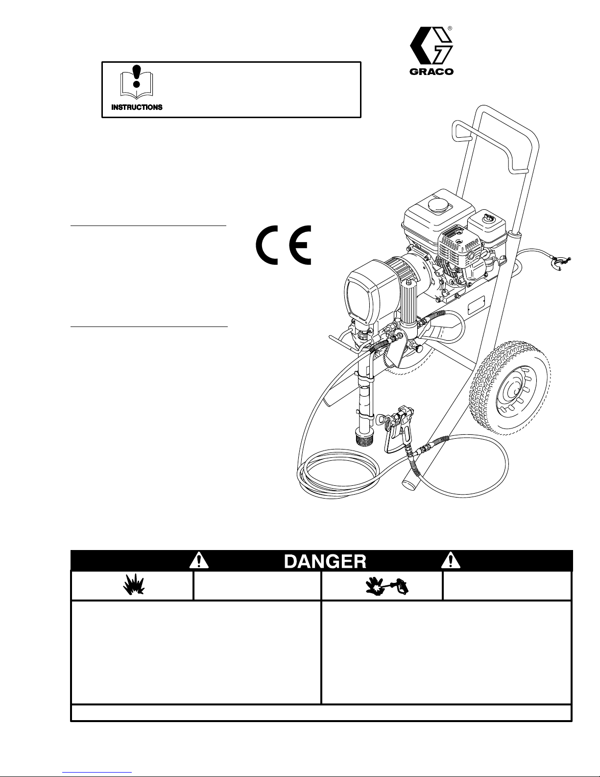
5 HORSEPOWER, GASOLINE–POWERED
307–847
Rev. L
Supersedes K
GM
5000
Airless
Paint Sprayer
3000 psi (210 bar) Maximum Working Pressure
Sprayers with Upright Carts
Model 220–886, Series C
Basic
sprayer
, without hose or gun
Model 231–052
Complete
RAC IV DripLess
and 517 size SwitchT
sprayer
, with hose and Contractor gun,
T
ip Guard,
ip
Sprayers with Lo–Boy Carts
Model 222–488, Series A
Basic
sprayer
, without hose or gun
Model 231–085
Complete
RAC IV DripLess
and 517 size SwitchT
sprayer
, with hose and Contractor gun,
T
ip Guard,
ip
NOTE: This
This label is available in other languages, free of charge. See page 42 to order
Spray
in confined areas can result in fire or explosion.
uids
Use
outdoors or
ment,
Avoid all ignition sources such as static electricity from plastic
cloths, open flames such as pilot lights, hot objects such as
drop
cigarettes,
turning
Failure
is an example of the DANGER label on your sprayer
painting, flushing or cleaning equipment with flammable liq
in extremely well ventilated areas. Ground equip
hoses, containers and objects being sprayed.
arcs from connecting or disconnecting
light switches on and off.
to follow this warning can result in death or serious injury
READ AND UNDERSTAND ALL LABELS AND INSTRUCTION MANUALS BEFORE USE
GRACO INC. P.O. BOX 1441
FIRE
AND
EXPLOSION HAZARD
power cords or
COPYRIGHT
.
.
SKIN INJECTION
HAZARD
Liquids can be injected into the body by high pressure airless
-
-
.
MINNEAPOLIS, MN
1987, GRACO INC.
or leaks – especially hose leaks.
spray
Keep
body clear of the nozzle. Never stop leaks with any part of the
body.
Drain
triggering
Never
In case of accidental skin injection, seek immediate “Surgical
Treatment”.
Failure
injury.
all pressure before removing parts. A
of gun by always setting safety latch
spray without a tip guard.
to follow this warning can result in amputation or serious
void accidental
when not spraying.
55440–1441
0136
Page 2

Table
of Contents
Introduction 2.
Warnings
English 4
French
Spanish
Setup 10
Fueling 11
Startup 12
Maintenance 14
Flushing Guidelines 15.
Troubleshooting Guide 16.
Repair
. . . . . . . . . . . . . . . . . . . . . . . . . . . . . . . . . . . . . . .
Bearing
Drive
Housing
Pinion 20
Clutch 22
Engine 23
Field
and Wiring Harness
. . . . . . . . . . . . . . . . . . . . . . . . . . . . . . . . .
. . . . . . . . . . . . . . . . . . . . . . . . . . . . . . . . . . . . .
(A
vertissement) 6.
(Advertencia)8. . . . . . . . . . . . . . . . . . . . . . . .
. . . . . . . . . . . . . . . . . . . . . . . . . . . . . . . . . . . . . .
. . . . . . . . . . . . . . . . . . . . . . . . . . . . . . . . . . . . . .
. . . . . . . . . . . . . . . . . . . . . . . . . . . . . . . . .
Housing & Connecting Rod
. . . . . . . . . . . . . . . . . . . . . . . . . . . . .
. . . . . . . . . . . . . . . . . . . . . . . . . . . . . . . . . . . . .
. . . . . . . . . . . . . . . . . . . . . . . . . . . . . . . . . . . . .
. . . . . . . . . . . . . . . . . . . . . . . . . . . . . . . . . . . . .
. . . . . . . . . . . . . . . . . . . . . .
. . . . . . . . . . . . . . . . . . . . . . . . .
. . . . . . . . . . . . . . . . . . . . . .
. . . . . . . . . .
. . . . . . . . . . . . . . . . . . . .
18.
19.
24.
Introduction
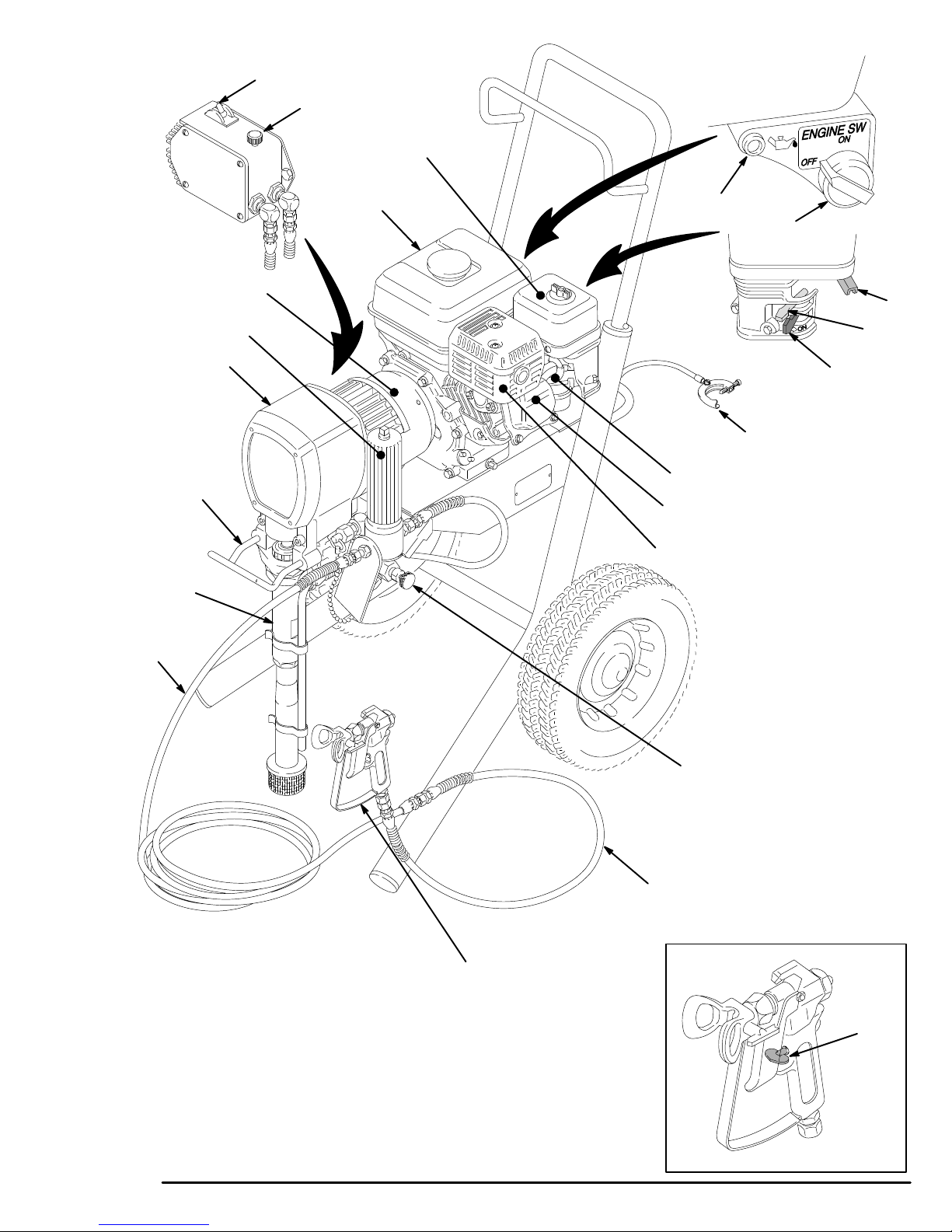
GM5000 BASIC COMPONENTS
NOTE: Refer to Fig.1.
Your
new GM5000 Sprayer functions and operates dif
ently than other airless paint sprayers. This section will
help
you become familiar with the sprayer before operat
ing
it.
Pressure Control
The
pressure control includes
sprayer, the pressure adjusting knob, and a pressuresensing device. The pressure control engages and disengages
the clutch to control pressure.
an ON/OFF switch for the
fer-
Clamp 25
Clutch
Reassembly 26
Pressure
Pressure
Displacement
Parts
Displacement Pump
Complete
Pinion 35
220–886,
222–488,
Pressure
Accessories 42
Technical
Dimensions 43
Graco
Warranty Back
Displacement Pump
The
vides
strokes.
Graco Throat Seal Liquid, helps prevent damage to the
-
throat
Fluid Filter
The
hose and spray tip. The filter includes a reusable element,
sure.
. . . . . . . . . . . . . . . . . . . . . . . . . . . . . . . . . . . . .
Housing
Control Replacement
Control Adjustment
Lists and Drawings
Sprayers
. . . . . . . . . . . . . . . . . . . . . . . . . . . . . . . . . . . . .
Basic Sprayer with Upright cart
Basic Sprayer with Lo-Boy cart
Control Assembly
Data
Phone Number
.
. . . . . . . . . . . . . . . . . . . . . . . . . . .
positive–displacement, volume-balanced pump pro
equal fluid delivery on both the up
The pump
packings and piston rod.
fluid filter strains the paint to help avoid clogs in
and a pressure drain valve for relieving fluid pres
. . . . . . . . . . . . . . . . . . . . . . . . . . . .
. . . . . . . . . . . . . . . . . . . . . . . . . . . . . . . .
. . . . . . . . . . . . . . .
. . . . . . . . . . . . . . . .
Pump Repair
. . . . . . . . . . . . . . . . . . . . . . . . .
. . . . . . . . . . . . . . . . . . . . . . . . . . . . . . . . .
. . . . . . . . . . . . . . . . . . . . . . . . . . . . . .
. . . . . . . . . . . . . . . . . . . . . . . . . . . . . . . . . .
has a wetcup which, when filled with
. . . . . . . . . . . . . . . . . .
. . . . . . . . . . . . . . . . . . . . . . . .
. . . . . . . . . . . . . . . . . .
. . . . . . . . . . . . . . . . . . . . . . .
and down pump
. . . . . .
. . . . . .
Cover
25.
28.
30.
31.
34.
35.
36.
38.
40.
43.
43.
-
the
-
Engine
The engine is a 5 horsepower, four stroke, gasoline engine. Its function is to drive the displacement pump to
supply paint. An adjustable throttle allows you to adjust
engine speed for large or small orifice spray tips. When
the
oil level is
you try to start the engine without refilling the oil, a
If
illuminates
engine
Clutch
The
clutch is engaged by the electric power generated by
the
gasoline engine.
switch.
sure
Drive Assembly
The
permanently greased drive assembly transfers pow
er
from the gasoline engine to the displacement pump.
too low
to alert you to the
from damage.
, the engine shuts of
problem, and to protect the
The power is controlled by the pres
f automatically
light
Hoses
The
grounded, nylon spray hoses have spring guards on
both
ends. The 50 ft. (15.2 m) hose has a 1/4 in. ID. The
3
ft. (0.9 m), 3/16
gun
movement. The
.
tion
dampener to absorb pressure fluctuations.
Spray Gun & RAC IV DripLess
Graco high pressure spray guns have a trigger safety
which prevents accidental triggering when the safety is
engaged.
also has a filter for final paint straining. The Reverse-A-
Clean
to
remove clogs from the spray tip without removing the
spray tip from the gun. The Reverse-A-Clean IV DripLess tip guard is a safety feature which helps reduce
the
See Fig. 1. The gun provided with the sprayer
IV (RAC IV) SwitchT
risk of a fluid injection injury
in. ID whip hose provides more flexible
nylon hose material acts as a pulsa
T
ip Guard
ip
uses high pressure
.
-
fluid
Page 3
A
B
C
202
0138
28
71
20
51
D
M
L
0015
4
K
J
0016
H
47
0136
G
F
E
53
KEY
A Pressure
switch
B
Pressure adjusting knob
C
Air cleaner
D
Fuel T
E Muffler
F Engine
G
Spark plug cable
H
Fuel shutof
J Choke
K Throttle
L
Engine ON/OFF switch
M
Engine oil light
NT
(shown engaged)
4 Clutch
20
Drive assembly
28
Displacement pump
47
Grounding wire and clamp
51
Fluid filter
53
Pressure drain valve
71
Pail hanger
202
Main hose
203
Whip end hose
204 “Contractor”
IV Dripless tip guard and
517 size SwitchT
Control ON/OFF
ank
f lever
rigger safety latch
gun with RAC
ip
Fig. 1
203
204
N
0137
Page 4
High
Observe All W
WARNINGS
Pressure Spray Can Cause Serious Injury
arnings. Read and understand all instruction manuals before operating equipment.
. For Professional Use Only.
FLUID
General
This
the
your
ry, including the need for amputation. Also, fluid injected or
splashed into the eyes or on the skin can cause serious damage.
NEVER
NEVER
to “blow back” paint; this is NOT an air spray system.
ALWAYS have the tip guard in place on the spray gun when
spraying.
ALWAYS
cleaning or removing the spray tip or servicing any system
equipment.
NEVER
Be
each
Medical
If any fluid appears to penetrate your skin, get EMERGENCY
MEDICAL CARE AT ONCE. DO NOT TREAT AS A SIMPLE
CUT.
Note
is
important to treat the injury surgically as soon as possible.
not
with some exotic coatings injected directly into the blood
stream. Consultation with a plastic surgeon or reconstructive
hand
Spray
Be sure all gun safety devices are operating properly before
each
cause
Safety
equipment generates very high fluid pressure. Spray from
gun, leaks or ruptured components can inject fluid through
skin and into your body
point the spray gun at any one or at any part of the body
put your hand or fingers over the spray
follow the
try to stop or deflect leaks with your hand or body
sure equipment safety devices are operating properly before
use.
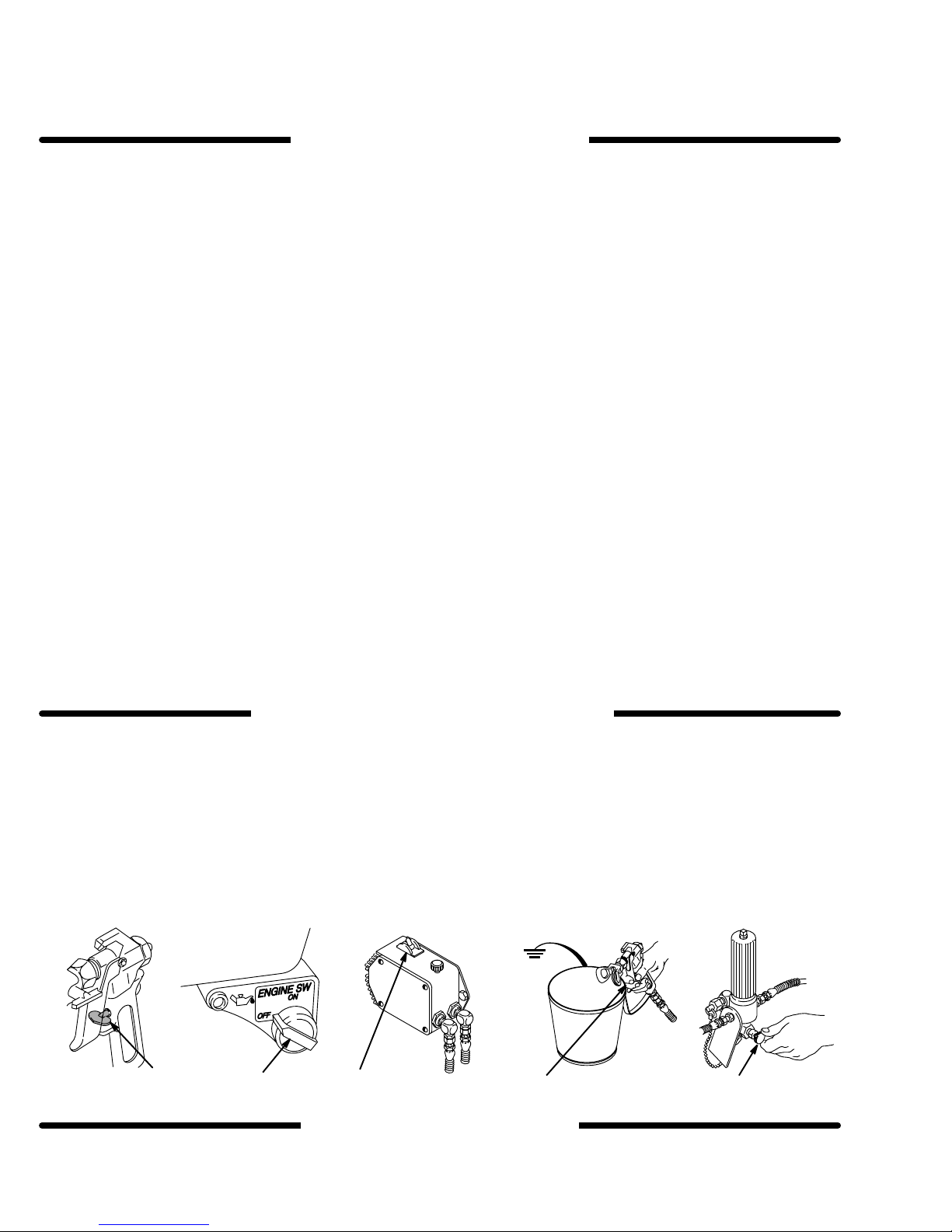
Pressure Relief Procedure
Alert––Airless Spray W
T
ell the doctor exactly what fluid was injected.
to Physician:
delay treatment to research toxicity
surgeon may be advisable.
, and cause extremely serious inju
ounds
Injection in the skin is a traumatic injury
.
T
oxicity is a concern
Gun Safety Devices
use. Do not remove or modify any part of the gun; this can
a malfunction and result in serious injury
PRESSURE
To reduce the risk of serious injury, including fluid injection,
splashing
moving parts or electric shock, always follow this procedure
whenever
any
ing
1
2 Turn the engine ON/OFF switch to OFF
3
4 Disengage the trigger safety latch. Hold a metal part of the
fluid or
solvent in the eyes or on the skin, or injury from
you shut of
part of the spray system, when installing, cleaning or chang
spray tips, and whenever you stop spraying.
Engage the trigger safety latch.
Flip the pressure control switch to OFF
gun
firmly to the side of a grounded metal pail, and trigger the
gun
to relieve pressure.
f the sprayer
, when
checking or servicing
.
.
INJECTION HAZARD
-
, before
.
.
It
Do
.
tip. NEVER try
, below
.
RELIEF
-
Safety Latch
Whenever you stop spraying, even for a moment, always set
the
trigger safety latch in the closed or
the
gun inoperative. Failure to set the safety latch can result
accidental
Diffuser
The gun diffuser breaks up spray and reduces the risk of fluid
injection
regularly
remove
gun
the gun. If the fluid emitted
stream,
T
ip Guard
ALWAYS have the tip guard in place on the spray gun while
spraying. The tip guard alerts you to the fluid injection hazard
and
placing
tip.
Trigger
Always
ing to reduce the risk of accidentally triggering the gun if it is
dropped
Spray T
Use extreme caution when cleaning or changing spray tips. If
the spray tip clogs while spraying, engage the trigger safety
latch
dure,
NEVER
is
fully relieved and the gun safety is engaged.
triggering of the gun.
when the tip is not installed. Check dif
. Follow the
the spray tip. Aim the gun into a metal pail, holding the
firmly to the pail. Using the lowest possible pressure, trigger
replace the dif
helps reduce, but does not prevent, the
your
fingers or any part of your body close to the spray
Guard
have the trigger guard in place on the gun when spray
or bumped.
Pressure Relief Procedure
is not
fuser immediately
ip Safety
immediately
below, and then remove the spray tip to clean it.
wipe of
. AL
WAYS
follow the
f build–up around the spray tip until the pressure
“safe” position, making
fuser operation
, below
diffused into an irregular
.
risk of accidentally
Pressure Relief Proce
in
, then
-
-
PROCEDURE
5
Engage the trigger safety latch.
6 Open the pressure drain valve. Leave the valve open until
you
are ready to spray again.
7
Disconnect the spark plug cable.
If
you suspect that the spray tip or hose
or that pressure has not been fully relieved after following the
steps
above,
VER
or
hose end coupling to relieve pressure gradually
completely.
Y SLOWL
Now clear the tip or hose.
Y loosen
is completely clogged,
the tip guard retaining nut
, then loosen
1,5
23 4
MOVING PARTS HAZARD
Moving
parts
parts.
the
sprayer
can pinch or amputate your fingers or other body
KEEP CLEAR of moving parts when starting or
. Follow the
Pressure Relief Procedure
operating
above be
6
checking or servicing any part of the sprayer
fore
from
-
starting accidentally
.
, to prevent it
0139
Page 5

EQUIPMENT MISUSE HAZARD
General
Any misuse of the spray equipment or accessories, such as
overpressurizing, modifying parts, using incompatible chemicals
to rupture and result in fluid injection, splashing in eyes or on
skin,
age.
NEVER alter or modify any part of this equipment; doing so
could
CHECK all spray equipment regularly and repair or replace
worn
Always
tor
Noise
Ear
Refer
Safety
and fluids, or using worn or
or
other serious injury
cause it to malfunction.
or damaged parts immediately
wear protective eyewear
as recommended by the fluid and solvent manufacturer
protection is recommended when the sprayer is operating.
to the Sound Level in the Technical Data
damaged parts, can cause them
, or fire, explosion or property dam
.
, gloves, clothing and respira
.
on page 43.
HOSE SAFETY
High
pressure fluid in the hoses can
hose develops a leak, split or rupture due to any kind of wear,
damage
cause
damage.
All
reliefs
the coupling which can result in hose rupture.
TIGHTEN
pressure
sure
NEVER
tire
movement of the hose couplings. If
ist, replace the hose immediately
pressure hose or mend it with tape or any other device. A repaired
or misuse, the high pressure spray emitted from it
a fluid injection injury or other serious
fluid hoses must have strain reliefs on both
help protect the hose from kinks or bends at or close to
all fluid connections securely before each use. High
fluid can dislodge a loose coupling or allow high pres
spray to be emitted from the coupling.
use a damaged hose. Before each use, check the en
hose for cuts,
hose cannot contain the high pressure fluid.
leaks, abrasion, bulging cover
be very dangerous. If the
can
injury or property
ends! The strain
, or damage or
any of these conditions ex
. DO NOT try to recouple high
System
This
Pressure.
are rated to withstand the this pressure. DO NOT exceed the
maximum working pressure of any component or accessory
used
-
Pressure
sprayer can develop 3000 psi (210 bar)
Be sure all spray equipment and accessories used
in the system.
Maximum Working
Fluid and Solvent Compatibility
All
chemicals used
ible
with the wetted parts shown in the Technical Data
43.
Consult your chemical supplier to ensure compatibility
not use 1,1,1-trichloroethane, methylene chloride, other ha
Do
-
logenated hydrocarbon solvents or fluids containing such solvents in this equipment, which contains aluminum and/or zinc
parts.
Such
the
possibility of explosion, which could cause death, serious in
jury
and/or substantial property damage.
Handle
and route hoses carefully
equipment.
of
the pump and gas engine. Do not use fluids or solvents which
are
not compatible with
NOT
expose Graco hoses to temperatures above 180 F
C)
or below –40 F (–40
in the sprayer must be chemically compat
use could result in a serious chemical reaction, with
. Do not pull on hoses to move
Keep hoses clear of moving parts and hot
the inner tube and cover of the hose. DO
C).
Hose Grounding Continuity
Proper
hose grounding continuity is essential to maintaining a
grounded
-
fluid
tag on it which specifies the maximum electrical resistance,
contact
sistance
-
for your hose to check the resistance. If the resistance exceeds
the recommended limits, replace it immediately. An ungrounded
ardous.
spray system. Check the electrical resistance of your
hoses at least once a week. If your hose does not have a
the hose supplier or manufacturer for the maximum re
limits. Use a resistance meter in the appropriate range
or poorly grounded hose can make
Also read
Fire Or Explosion Hazard
your system haz
, below
on page
.
surfaces
(82
.
-
-
-
-
-
Static
electricity is created by the flow of fluid through the pump
and hose. If every part of the spray equipment is not properly
grounded, sparking may occur, and the system may become
hazardous. Sparking may also occur when plugging in or unplugging a power supply cord or using a gasoline engine.
Sparks can ignite fumes from solvents and the fluid being
sprayed, dust particles and other flammable substances,
whether you are spraying indoors or outdoors, and can cause
a fire or explosion and serious injury and property damage.
If you experience any static sparking or even a slight shock
while
using
Check the entire system for proper grounding. Do not use the
this equipment, ST
system again until the problem has been identified and corrected.
OP SPRA
Grounding
To
reduce the risk of static sparking, ground the sprayer and
other spray equipment used or located in the spray area.
CHECK
tions
all
1.
NEVER
spilled
ALWAYS
Explosion Hazard
United
General Standards, Part 1910, and the Construction Standards, Part 1926 – should be consulted.
your local electrical code for
for your area and type of equipment. BE SURE to ground
of this spray equipment:
Sprayer:
true
connect a ground wire and clamp (supplied) to a
earth ground.
fill the fuel tank while the engine is running or hot. Fuel
on a hot surface can ignite and cause a fire.
pour fuel in slowly
, above, and
States Government safety standards have been adopted under the Occupational Safety and Health Act.
to avoid spilling. Also read
Fueling
FLUID
YING IMMEDIA
detailed grounding instruc
GASOLINE
on page 1
INJECTION HAZARD
TELY.
all
ENGINE HAZARD
Fire Or
1.
IMPORTANT
2.
Fluid hoses:
500 ft (150 m) combined hose length to ensure grounding
continuity.
Spray gun:
3.
erly
grounded fluid hose and sprayer
Object being sprayed:
4
5.
Fluid supply container:
6.
All
solvent pails used when flushing,
Use
only metal pails, which are conductive. Do not place the
pail on a non–conductive surface, such as paper or cardboard,
To maintain grounding continuity when flushing or relieving
7.
pressure
of
a grounded metal pail, then trigger the gun.
Flushing
Reduce the risk of fluid injection injury, static sparking, or
-
splashing
of
this manual. Follow the
4, and remove the spray tip before flushing. Hold a metal part
of
the gun firmly to the side of
lowest
possible fluid pressure during flushing.
NEVER
gine exhaust is piped outside. The exhaust contains carbon
monoxide, a poisonous, odorless and invisible gas which can
cause
serious illness and even death of inhaled.
use only grounded hoses with a maximumf
See
Hose Grounding Continuity, above.
obtain grounding through connection to a prop-
according to local code.
according to local code.
which interrupts the grounding continuity
,
always hold a metal part of the gun firmly to the side
.
according to local code.
Safety
by following the flushing procedure given on page 15
operate the engine in a closed building unless the en
Pressure Relief Procedure
a grounded metal pail and use the
These standards – particularly the
307-847 5
.
on page
-
Page 6
Avertissement
La
pulvérisation à haute pression peut causer des blessures très graves.
Réservé exclusivement à l’usage professionnel. Observer toutes les consignes de sécurité.
Bien lire et bien comprendre tous les manuels d’instructions avant d’utiliser le matériel.
RISQUES D’INJECTION
Consignes
Cet
appareil produit un fluide à très haute pression. Le fluide pul
vérisé
tes
ou de ruptures peut pénétrer sou la peau ou à l’intérieur du
corps
putation.
ou
entrant dans les yeux peut aussi entraîner des blessures gra
ves.
Ne
jamais
quelconque du corps. Ne jamais mettre le main ou les doigts
sur
l’ajutage du pulvérisateur. Ne jamais
la
peinture. Cet appareil
que.
TOUJOURS garder la protection de l’ajutage en place sure le
pistolet
TOUJOURS observer la Marche à Suivre Pour Détendre la
Pression donnée plus
tage
une
partie de l’appareil.
NE
JAMAIS essayer d’arrêter ou de dévier le fuites avec la main
ou
le corps.
Avant chaque utilisation, bien s’assurer que les dispositifs de
sécurité
Soins médicaux
En
cas de pénétration de fluide sous la peau:
MEDIATEMENT DES SOINS MÉDICAUX D’URGENCE. Ne
pas
soigner cette blessure comme une simple coupure.
Avis
un
traumatisme.
cette
pour effectuer des recherches sur la toxicité. Certains revêtements
injectés directement dans le sang. Il est souhaitable de consul
ter un chirurgien esthétiques ou un chirurgien spécialisé
la reconstruction des mains.
Dispositifs de sécurité du pistolet
Avant
de
sécurité du pistolet fonctionnent correctement.
ver
ni modifier une partie quelconque du pistolet; ceci risquerait
d’entraîner un mauvais fonctionnement et des blessures graves.
Pour
sures par projection de fluide ou celles causées par de éclaboussures
vement, toujours bien observe cette marche à suivre chaque
fois
que l’on arrête le pulvérisateur
du
Égale ou du nettoyage du système ou lors du
des ajutages.
1.
Engager le verrou de sécurité du pistolet.
2
Mettre le levier d’arrêt du moteur sur ARRET (OFF).
3 Basculer l’interrupteur de commande de pression sur AR-
RET (OFF).
4 Désengager
nant une partie métallique du pistolet fermement appuyé
contre
libérer
générales de sécurité
par le pistolet ou le fluide sous pression provenant de fui
et entraîner des
Même
pointer le pistolet vers
pendant la pulvérisation.
du pulvérisateur
fonctionnent correctement.
au
médecin:
blessure immédiatement.
exotiques sont
blessures très graves, voir même une am
sans être sous pression, le fluide éclaboussant
quelqu’un ou vers une partie
N’est P
loin,
avant
, ou d’ef
AS un compresseur pneumati
fectuer un travail quelconque sur
essayer de “refouler”
de nettoyer ou d’enlever l’aju
DEMANDER
La pénétration des fluides sous la peau est
Il est important de traiter chirurgicalement
Ne pas retarder le traitement
dangereusement toxiques quand ils sont
IM
-
-
-
-
-
-
-
-
dans
chaque utilisation, bien s’assure que
tous les dispositifs
Ne pas enle
-
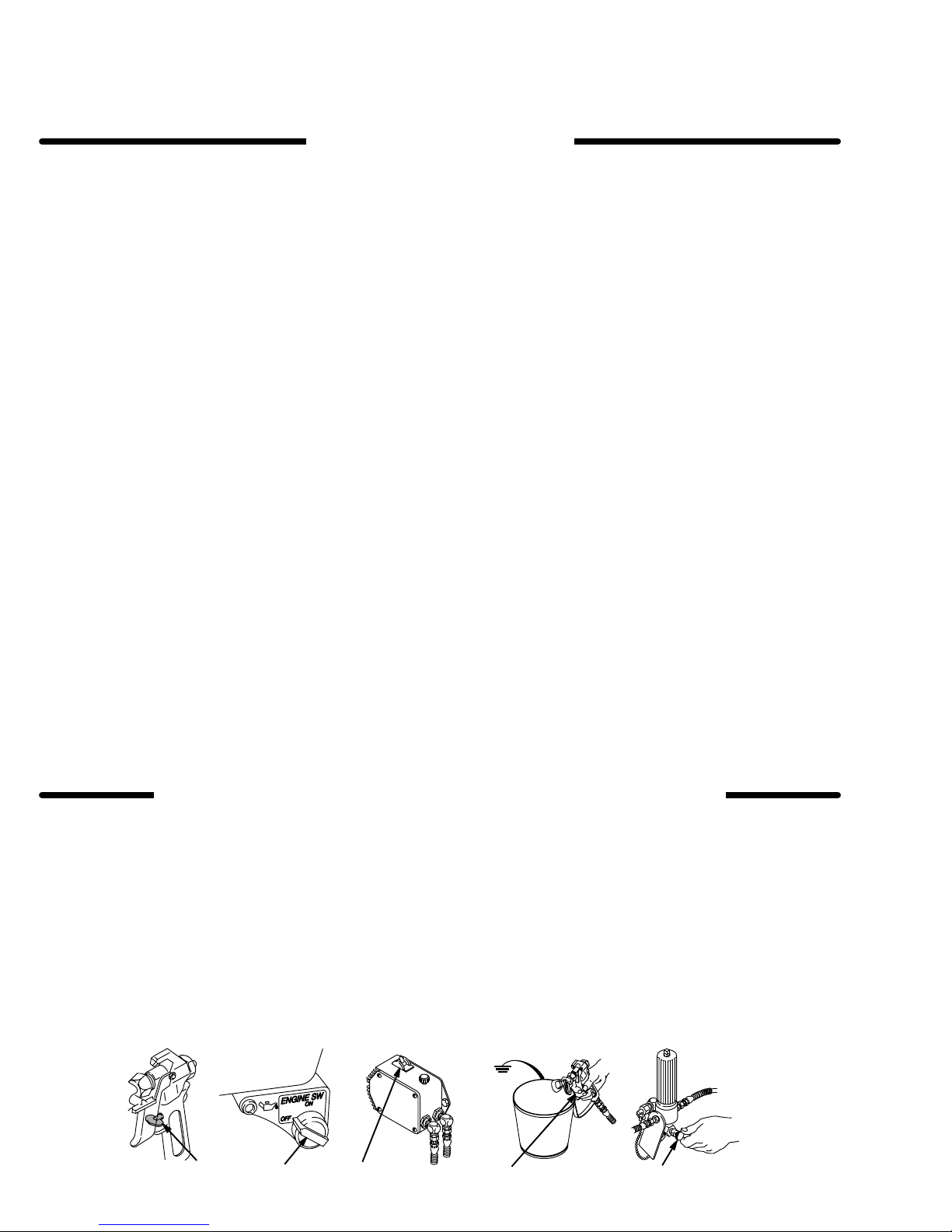
MARCHE A SUIVRE POUR DÉTENDRE LA PRESSION
réduire les risques de blessures graves, y compris les bles
dans les yeux ou sur la peau, par des pièces en mou
le verrou de sécurité
le côte d’un seau en
la pression.
, à l’occasion de la vérification,
du pistolet. T
métal, actionner le pistolet pour
changement
out en mainte
-
-
-
Verrou
de sécurité
A chaque fois que l’on s’arrête de pulvériser, même s’il s’agit
d’un
court instant, toujours mettre le verrou de sécurité du pisto
let
sur la position, “fermée” ou “sécurité” (“safe”), pour empêcher
le
pistolet de fonctionner
le
pistolet peut se déclencher accidentellement.
. Si le verrou de sécurité n’est pas mis,
Diffuseur
Le
dif
fuseur du pistolet sert à diviser le jet et à réduire les risques
d’injection
fier
rification,
Pour
pulvérisateur. Pointer le pistolet dans un seau en métal, en le
maintenant
sion
Si le fluide projeté
remplacer
accidentelle quand l’ajutage
le fonctionnement du
détendre la pression en observant la Marche à Suivre
Détendre la Pression donnée plus loin enlever l’ajutage du
fermement contre le seau. Puis, en utilisant la pres
la plus faible possible, appuyer sur la gâchette du pistolet.
immédiatement le dif
dif
n’est pas
fuseur régulièrement. Pour cette vé
dif
fusé sous forme de jet irrégulier
n’est pas en place. Véri
fuseur.
Protection de l’ajutage
TOUJOURS
pistolet
de
l’ajutage attire l’attention sur les risques d’injection let contri
bue
à réduire, mai n’évite pas le risque, que les doigts ou une
partie quelconque du corps ne passent accidentellement à
proximité
Consignes de sécurité concernant l’ajutage
du pulvérisateur
Faire
remplacement des ajutages du pulvérisateur. Si l’ajutage se
bouche
rou
de sécurité du pistolet. T
à Suivre Pour Détendre la Pression puis enlever l’ajutage du
pulvérisateur
NE
JAMAIS essuyer
du pulvérisateur avant que la pression ne soit complètement
tombée
5
Engager le verrou de sécurité du pistolet.
6 Ouvrir
que
7
Débrancher le fil de la bougie.
Si l’on soupconne que le tuyau ou l’ajutage est
maintenir la protection de l’ajutage en place sur le
du pulvérisateur pendant la
immédiate de l’ajutage du pulvérisateur
extrêmement attention à l’occasion du
pendent la pulvérisation, mettre immédiatement le ver
pour le nettoyer
ce qui s’est accumulé autour de l’ajutage
et que le verrou
la soupape de
l’on soit prêt à se servir de nouveau du pulvérisateur
de sécurité du pistolet ne soit engagé.
sécurité et la laisser ouverte jusqu’à ce
pulvérisation. La protection
.
nettoyage ou due
OUJOURS bien observe la Marche
.
complètement
.
bouché ou que la pression n’a pas été complètement libérée
après
avoir procédé aux opérations
lentement
la
protection
un raccord de bout de tuyau ou l’écrou de retenue de
de l’ajutage et libérer progressivement la pression.
ci–dessus, desserrer
Tres
-
-
-
,
-
-
1,5
23 4 6
307-8476
0139
Page 7

RISQUES EN CAS DE MAUVAISE UTILISATION DU MATERIAL
Consignes
Toute
accessoires comme, par exemple, la mise sous une pression
excessive,
chimiques
usées
ruptures
tres blessures sérieuses, un incendie, une explosion ou d’autres
dégâts.
Toujours
tements protecteur et un dispositif pour la respiration correspondant
vants.
Pression
pulvérisateur peut
Ce
TRAVAIL 210 bar (3000 lb/po.@)
ments
sister
PAS
ments
Compatibilité chimique des corps
BIEN
chimiquement compatibles avec les parties mouillées indiquées
soigneusement les documents et brochures du fabricant des
fluides
sateur.
Le fluide à haute pression circulant dans les tuyaux peut être
dangereux. En cas de
très
re
ou rupture à la suite de l’usure, de dégâts
utilisation, les projections de fluide haute pression qui en proviennent
tion
sous la peau ou par contact, ainsi que des dégâts matériels.
générales de sécurité
utilisation anormale de l’appareil du
les modifications de pièces, l’utilisation de produits
et
de matières incompatibles et l’utilisation de pièces
ou abîmées peut causer des dégâts à
de pièces et entraîner une
porter une protection pour les yeux, de
aux recommandations des fabricants de
produire une
du pulvérisateur et ses accessoires sont conçus pour ré
à la pression maximum de travail de ce pulvérisateur
dépasser la pression maximum de travail d’aucun des élé
ou accessoires utilisés avec cet appareil.
S’ASSURER que tous les corps des solvants utilisés sont
dans les “Données techniques”, à page 43. T
et solvants utilisés avant de s’en servir dans ce pulvéri
fuite sur le tuyau, de fissure, déchiru
peuvent entraîner des blessures graves par pénétra
pulvérisation ou des
l’appareil ou des
injection de liquide ou d‘au
gants, des vê
fluides et sol
PRESSION MAXIMUM DE
S’assurer que tous les élé-
. NE
oujours lire
ou d’une mauvaise
Tous les tuyaux flexibles doivent avoir des ressorts spirale de
protection aux 2 bouts! Les spirales de protection contribuent
à
éviter la formation de pliures, de boucles ou de nœuds sur les
tuyaux
qui pourraient entraîner la rupture du tuyau à l’endroit du
raccord
Serrer
fluide sous pression peut faire sauter un raccord desserré ou
produire
NE
refaire le raccord d’un tuyau haute pression ni de réparer le
tuyau
réparé
Manipuler
leur
pas
-
bles
exposer
-
(180_F)
Continuité de la mise à la terre des tuyaux
Une
tielle
tion.
à
te pas d’étiquette qui précise
-
prenez contact avec le fournisseur de tuyaux ou la fabricant
pour
de
-
fiez la résistance. Si celle–ci dépasse les limites recommandées,
à
-
des risques pour votre système. Lisez aussi LES RISQUES
D’INCENDIE OU D’EXPLOSION.
ou à son voisinage.
fermement tous les raccords avant chaque utilisation. Le
un jet à haute pression s’échappant par le raccord.
JAMAIS utiliser un tuyau endommagé. NE P
avec du ruban adhésif
ne peut pas résister au fluide sous pression.
les tuyaux avec precaution
chemin. Ne pas déplacer le fluide en tirant sur le tuyau. Ne
utiliser de fluides ou de solvants que ne sont pas compati
avec l’enveloppe intérieur ou extérieure de tuyau. NE P
le tuyau à fluides des températures
ou inférieures à –40_C (–40
bonne continuité de la mise à la terre des tuyaux est
pour maintenir la mise à la terre de l’ensemble de vaporisa
Vérifiez la résistance électrique de vos tuyaux à fluides et
air
, au moines
avoir les limites de résistance maximum. Utilisez un mètre
résistance de la gamme appropriée pour votre tuyau et véri
remplacez le tuyau immédiatement. Un tuyau sans mise
la terre ou avec une mise à la terre incorrecte peut entraîner
une fois par semaine. Si votre tuyau ne compor
ou par tout autre moyen. Un tuyau
et choisir soigneusement
supérieures à 82
_F).
la
résistance électrique maximum,
AS essayer de
AS
_C
essen
-
-
-
-
-
RISQUES D’INCENDIE OU D’EXPLOSION
De
l’électricité statique est produite par le passage du fluide à
grande
vitesse dans la pompe et dans les tuyaux. Si toutes les
pièces de l’appareil de pulvérisation ne sont pas convenablement
reliées ou à la masse
se
produire et l’appareil risques d’être dangereux. Des étincel
les peuvent Également se produire à l’occasion du branchement
ou du débranchement du cordon d’alimentation
lisation
d’un moteur à essence. Les
pour
allumer les vapeurs de solvants et le
fines
particules de poussière ainsi que d’autres substances in
flammables,
elles peuvent causer un incendie ou une explosion, ainsi que
des
blessures graves et des dégâts matériels.
S’il
se produit des étincelles d’électricité statique, ou si vous res
sentez
PULVERISATION.
me
soit identifié et corrigé.
Mise à la terre ou à la masse
Pour
statique,
trouvant dans la zone de pulvérisation doivent être reliés à la
terre
mise
CONSULTER
les.
S’ASSURER que tous le équipements de pulvérisation sui
vants
1
Pulvérisateur:
une bonne terre.
quand on pulvérisé à l’intérieur ou à l’extérieur
la moindre décharge, ARRETEZ IMMEDIA
Vérifiez que le système avant que le problè
réduire les risques de production d’étincelles d’électricité
le pulvérisateur et tous les équipement utilisés ou
ou à la masse.
à la terre dans la région et le type particulier d’équipement,
le code
sont bien reliés à la terre:
Relier le file de masses et le collier (fourni) à
ou à la terre, des étincelles peuvent
étincelles sont suf
fluide pulvérisé, les
Pour connaître le détail des instructions de
ou les réglementations électriques loca
ou de l’uti
fisantes
, et
TEMENT LA
se
-
-
-
-
-
2 Pistolet:
tuyau flexible et à une pulvérisateur déjà convenablement
reliés
3
Tuyaux
terre,
et ayant une longueur maximum combinée de 150 m (500
pieds).
du circuit de mis à la terre des tuyaux”.
4
Récipient
tations
5
Objets,
ver
6
Tous
code ou les réglementations locales.
seaux
le
pier ou du carton car cela interromprait la continuité de la
mise
7
Pour conserver la continuité de la mise à la terre quand on
Réaliser la mise à la terre en le raccordant à une
à la terre.
flexibles:
n’utiliser que des tuyaux comportant
Se reporter également au paragraphe,
locales.
matériel ou surfaces recevant
le code ou les réglementations locales.
le seaux de solvant
Afin d’assurer la continuité
d’alimentation:
observer le code ou les réglemen
utilisés pour le rinçage: observer le
une mise à la terre
la pulvérisation:
N’utiliser que des
métallique
seau sur une surface non conductrice comme sur du pa
à la terre.
conducteurs de l’électricité. Ne pas mettre
rincé le matériel ou quand on libère la pression,
maintenir une partie métallique du pistolet fermement appuyée
contre le côté d’un seau
détente
-
Mesures de Sécurité concernant le Rinçage
Pour réduire les risques de blessures par pénétration de la
peau et les risques dûs aux étincelles d’électricité statique ou
aux
donnée
du pistolet.
éclaboussures, observe la marche
à la page 15 de ce manuel.
en
métal
puis appuyer sur la
à suivre pour le rinçage
de la mise à la
“Continuité
obser
toujours
-
-
-
MESURES DE SECURITE CONCERNANT LES TUYAUX FLEXIBLES
NE
JAMAIS remplir le réservoir de carburant
tourne
ou quand
face chaude peut s’enflammer et causer un incendie. TOUJOURS
Lire RISQUES D’INCENDIE OU D’EXPLOSION.
verse le carburant
il est chaud. Le carburant renversé sur une sur
lentement pour éviter d’en renverser
quand le moteur
JAMAIS faire tourner un moteur dans un bâtiment fermé à
NE
-
moins
que les gaz d’échappement ne soient dirigés au dehors.
Les
.
gaz d’échappement contiennent de l’oxyde de carbone,
gaz
toxique, inodore et invisible qui peut entraîner des malaises
graves
ou même la mort se l’on le respiré.
un
Page 8
ADVERTENCIA
EL
ROCIADO a ALTA PRESIÓN PUEDE CAUSAR GRA
SOLO P
ARA USO PROFESIONAL. RESPETE LOS A
VISOS DE ADVERTENCIA.
Lea y entienda todo el manual de instrucciónes antes de manejar el equipo.
PELIGRO DE INYECCION DE FLUIDO
VES LESIONES.
Seguridad
Este
equipo general un fluido a una presión muy alta. El rociado
de
la pistola, los escapes de fluido o roturas de los componen
tes
pueden inyectar fluido en la piel y el cuerpo y causar lesio
nes
extremadamente graves,
de amputación. T
ojos
puede causar graves daños.
NUNCA
po.
NUNCA colocar la mano o los dedos encima de la boquilla.
NUNCA
tema
SIEMPRE
mientras
SIEMPRE
dado más abajo,
servicio
NUNCA
cuerpo.
Asegurar
funcionando
Tratamiento
Si pareciera que un poco de fluido penetró la piel, conseguir
TRATAMIENTO MEDICO DE URGENCIA DE INMEDIATO.
NO
TRATAR LA HERIDA COMO UN SIMPLE CORTE.
al
médico
Aviso
se
causa una lesión traumática.
gicamente
tratamiento para investigar
de sumar importancia en algunas pinturas exóticas cuando
se
inyectan directamente al torrente sanguíneo. Sirá conve
niente consultar a un especialista en cirugía plástica o reconstructiva
general
ambién, el
apuntar la pistola
tratar de “hacer retornar la pintura”; este NO es un sis
de rociado de aire.
tener
colocado el protector de la boquilla en la pistola
se está pulverizando.
seguir el procedimiento de descarga de presión,
a cualquier del sistema.
tratar de parar o desviar los escapes
que todos los aparatos de seguridad del equipo están
antes
bien antes de cada uso.
incluyendo a veces la necesidad
fluido
inyectado o salpicado en los
hacia alguien o alguna parte del cuer
de limpiar o sacar la boquilla o de dar
con la mano o el
médico
exactamente cua fluido fue.
al médico:
Si se llega a inyectar este fluido en la piel
la lesión a la
de las manos.
Es importante tratar quirúr
brevedad posible.
la
toxicidad. La toxicidad es algo
No demorar el
Decir
Aparatos
Asegurar
-
funcionando
-
guna pieza de la pistola pues podría causar el malfuncionamiento
Pestillo
Cada
-
momento, siempre colocar el pestillo de seguridad en la posición
-
puede llevar al disparo imprevisto de la pistola.
Difusor
El
difusor de la pistola dispersa el chorro pulverizado y reduce
el
riesgo
visar con regularidad el funcionamiento del difusor. Seguir el
procedimiento
pués sacar la boquilla. Apuntar la pistola a un balde metálico,
sosteniéndola bien firme contra él. Utilizando la presión más
bajo
perso
Protector
SIEMPRE
mientras
contra
la
colocación accidental de los dedos o cualquier otra parte del
cuerpo
Seguridad
Tener
ra
-
-
a obstruirse mientras está pulverizando, enganchar el
llo
de la
de descarga de presión y después sacar la boquilla para limpiarla
NUNCA limpiar la acumulación de pintura alrededor de la boquilla
y
el pestillo esté enganchado.
de seguridad de la pistola pulverizadora
que todos los aparatos protectores de la pistola están
bien antes de cada uso. No sacar ni modificar nin
de
la misma con las consiguientes lesiones personales.
de seguridad
vez que se deje de pulverizar
“cerrada”, lo que deja la pistola inoperante. El no hacerlo
de inyección cuando no está instalada la boquilla. Re
de descarga de presión, dado más abajo, y des
posible, disparar la pistola. Si el fluido emitido
en un
chorro irregular
de la boquilla
tener
el protector de la boquilla colocado en la pistola
se está pulverizando.
el peligro de inyección
cerca de la boquilla.
, reemplazar de inmediato el difusor
, aunque sea por un breve
Este protector llama la atención
y ayuda a reducir
de la boquilla pulverizadora
mucho cuidado al limpiar o cambiar las
pistola de inmediato. SIEMPRE seguir el procedimiento
antes de que se haya descargado por completo la presión
boquillas. Si llega
no sale dis
, pero no evita,
pesti
-
-
-
-
.
-
-
PROCEDIMIENTO
Para
reducir el
cluyendo la inyección de
piel, o lesiones causadas por piezas en movimiento, siempre
seguir
este procedimiento al apagar la máquina pulverizadora,
al
revisar
1 Enganchar
2
Mover el interruptor de parada del motor a OFF
Mover el interruptor de control de presión a OFF
3
4 Desenganchar
ner
una parte metálica de la pistola firmemente contra el
de un balde de metal y activar la pistola para descargar la
presión.
riesgo de sufrir graves lesiones corporales, in
, ajustar o limpiar el sistema, o al cambiar las boquillas.
el pestillo de seguridad de la pistola.
fluidos, salpicaduras en los ojos o la
el pestillo de seguridad de la pistola.
1,5
23 4 6
DE DESCARGA DE
5 Volver
6 Abrir la válvula de alivio de presión y dejarla abierta hasta
que
se esté nuevamente listo para pulverizar
7
Desconectar el cable de la bujía.
.
.
Mante
lado
Si se sospecha que la boquilla o la manguera esté completamente obstruida, o que no se ha descargado por completo la
presión después de haber seguido el procedimiento anterior,
-
aflojar
MUY LENTAMENTE un adaptador de extremo de la
manguera o la tuerca de renención del protector de lay punta
y
descargar gradualmente la presión.
PRESION
a enganchar el pestillo de seguridad de la pistola.
.
0139
Page 9

PELIGRO POR MAL USO DEL EQUIPO
Seguridad
Cualquier
como sobre presurización, modificación de piezas,
teriales y productos químicos incompatibles, o utilización de
piezas dañadas o desgastadas, puede hacen que se rompan
y
causen la inyección de fluido u otras lesiones corporales
ves,
incendio, explosión o daños a la propiedad.
Siempre
piradero,
solvente.
general
mal uso del equipo pulverizador o los accesorios, tal
usar gafas, guantes, vestimentas protectoras
tal como recomiendan los fabricantes del fluido y del
uso de ma
gra
y un res
SEGURIDAD EN EL USO DE LAS MANGUERAS
El fluido que escapa a alta presión por las mangueras puede
ser
muy peligroso. Si en la manguera se desarrola un escape,
una
rotura o rajadura debido a cualquier tipo de desgaste, daño
o maltrato, el chorro a alta presión emitido por allí puede
una lesión por inyección u otras lesiones corporales graves o
daños
a la propiedad.
¡Todas
las mangueras para fluidos tienen que tener guardas de
resorte en ambos extremos! Estas protegen las mangueras
contra dobleces o retorceduras en los acoplamientos o cerca
de
ellos, los que podrían traducirse en roturas de la manguera.
Antes de usarlas, APRET
El fluido a lata presión puede desalojar un acoplamiento suelto
o
dejar que pro él escape un chorro a alta presión.
NUNCA
la
da, o acoplamientos sueltos o dañados. Si llegara a encontrar
se cualquiera de estas condiciones, reemplazar de inmediato
la
sión o enmendarla con cinta adhesiva u otro material similar.
Una
alta
usar una manguera que está dañada. Siempre revisar
en busca de cortaduras, escapes, abrasión, cubierta
manguera. NO intentar reacoplar una manguera de alta pre
manguera que ha sido remendada no aguante
presión.
AR bien firmes
todas las conexiones.
causar
abulta
el fluido al
Presión
Esta
-
PRESION
po pulverizador y sus accesorios tienen la capacidad para
aguantar
-
o
accesorio de este sistema.
Compatibilidad de fluido
Siempre
te
Manejar y pasar cuidadosamente las mangueras. No tirar de
las
tes
la
82) C
Continuidad
del sistema
pulverizadora puede desarrollar 210 barías (3000 psi) de
DE
TRABAJO MAXIMA.
la presión máxima de trabajo
leer las instrucciones del fabricante del fluido y solven
antes de usarlos en esta pulverizadora en la página 43.
mangueras para mover el equipo. No usar fluidos o solven
que sean
manguera. NO exponer las mangueras a temperaturas sobre
incompatibles con el tubo interno y la cubierta de
(180_F) o bajo -40
_C (-40_
Asegurar que todo el equi
de ningún componente
F).
del circuito de puesta a tierra de la
manguera
La continuidad del circuito de puesta a tierra apropiado es
esencial
dor
las
mana. Si la manguera no tiene una etiqueta en la cual se espe
cifica la resistencia eléctrica máximum, ponerse en contacto
con
ción
-
cia
-
cede los lites recomendados, reemplazarla de inmediato. Es
-
muy arriesgado tener una manguera sin puesta a tierra o con
la
-
mación sobre RIESGO DE INCENDIO O EXPLOSION, más
arriba.
para mantener conectado a tierra el sistema pulveriza
. Es indispensable revisar la resistencia eléctrica máxima de
mangueras de aire y de fluido por lo menos una vez
el proveedor o
sobre los límites
en la gama apropiada para
puesta a tierra en malas condiciones. Leer también la infor
fabricante de la manguera para la informa
de resistencia. Usar un metro de resisten
comprobar la resistencia; si ex
a la se
-
-
-
-
-
-
-
-
-
-
PELIGRO DE INCENDIO O EXPLOSION
El
flujo a alta velocidad del fluido al pasar por la bomba y man
guera
crea electricidad estática. Si todas las partes del
pulverizador no tienen buena tierra, pueden ocurrir chispas,
convirtiéndo al sistema en algo peligroso. También, pueden
producirse
co
o al usar un motor de gasolina. Estas chispas pueden infla
mar
do, partículas de polvo y otras sustancias inflamables, sea al
aire
cendio
Si
ocurre una chispa de electricidad estática o incluso un ligero
choque
RIZAR DE INMEDIATO. Revisar todo el sistema en busca de
una
identificado
Puesta
Para
pulverizadora
se
encuentre en el lugar que se va a rociar
digo eléctrico de la localidad para las instrucciones sobre las
conexiones
GURAR
1
Pulverizadora:
(suministrada)
chispas al enchufar o desenchufar el cordón eléctri
los vapores de los solventes y el chorro de fluido pulveriza
libre o bajo techo, lo que podría causar una explosión o in
y graves lesiones corporales y daños a la propiedad.
eléctrico mientras se usa el equipo, DEJAR DE PUL
tierra apropiado. No usar de nuevo el sistema hasta haber
y solucionado el problema.
a tierra
reducir el riesgo de chispas estáticas, conectar a tierra la
y todo el otro equipo de pulverizar que se use o
a tierra exigidas para la zona y tipo de equipo. ASE
de conectar a tierra todo este equipo pulverizador:
Conectar el alambre de tierra
a una buena conexión a tierra.
. CONSULTAR el
y la abrazadera
equipo
VE-
có
-
2
Mangueras para fluidos:
puesta a tierra de una longitud combinada de 150 m (500
pies), para asegurar buena continuidad a tierra. Referirse
-
-
-
-
también
3
Pistola:
ra
4
Suministrar un recipiente:
solamente
car
cartón, que interrumpe la continuidad a tierra.
5
Objeto
local.
6
Todos los baldes de solvente
conformidad con el código local.
7
Para mantener la continuidad a tierra durante el lavado o
descarga
la
pués
-
Seguridad durante el lavado
Para
-
piel, o que ocurra una descarga de electricidad estática,
pre
seguir las INSTRUCCIONES P
la
página 15. Seguir el procedimiento de descarga de presión
en
la
baja
al párrafo sobre continuidad a tierra de la manguera.
hacer la puesta a
de fluido y pulverizadora bien conectadas a tierra.
baldes de metal,
el balde en una superficie no conductiva, como papel o
que se está rociando:
de
pistola bien firme contra el costado
reducir el riesgo
página 8, y quitar la
posible de fluido durante el lavado.
presión,
apretar el gatillo.
usar solamente mangueras con
tierra conectándola a una mangue
de acuerdo al código local. Usar
que sean conductivos. No colo
de conformidad con el código
usados durante
siempre apoyar una parte metálica de
de
de que se inyecte o salpique fluido en la
ARA EL LAVADO, dadas
boquilla de metal
-
-
el lavado, de
balde de metal
y usar le presión más
, des
siem
en
-
-
PRECAUCIONES PARA LOS MOTORES DE GASOLINA
NUNCA
funcionando o caliente. El combustible derramado en una superficie caliente puede encenderse y provocar un incendio.
SIEMPRE verter el combustible lentamente para evitar derra-
mes. Leer PELIGRO DE INCENDIO O EXPLOSION.
llenar el tanque de combustible mientras el motor está
NUNCA
caminar
escape
olor
so
hacer funcionar el motor en un edificio cerrado sin en–
los gases de escape hacia el aire libre. Los gases
contienen monóxido de carbono, un
e invisible que podría causar enfermedades graves, inclu
la muerte, al inhalarse.
gas venenoso, sin
307-847 9
de
-
Page 10
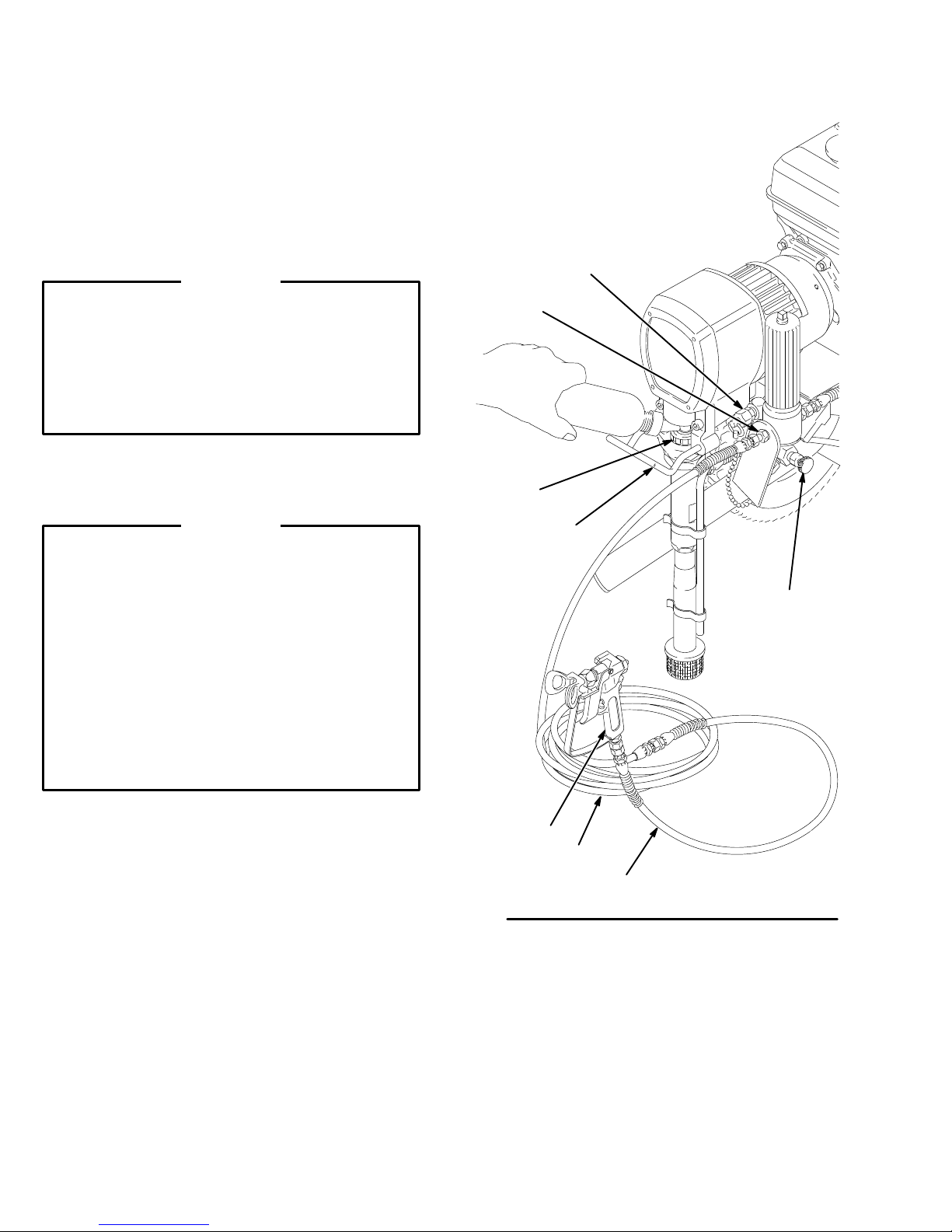
Setup
1. Connect hose and gun.
a. Remove
the plastic cap plug from
(Refer to Fig. 2.)
the filter outlet
nipple (57) and screw the 50 ft. (15.2 m) main
hose (202) onto the nipple.
fluid
b. Connect the whip end hose (203) between the
main
c. DO
the
fluid hose and
NOT use thread sealant, and DO NOT install
spray tip yet!
the gun (204) inlet adapter
WARNING
If you are supplying your own hoses and spray gun,
be
sure the hoses are electrically conductive, that
gun
has a tip guard, and that each part is
least
3000 psi (210 bar) Maximum Working Pressure
This
is to reduce the risk
of serious injury caused by
rated for at
static sparking, fluid injection or over-pressurization
and
rupture of the hose or gun.
2. Two
gun hookup.
(Refer to Fig. 2.) Remove the cap
(56) from the secondary hose outlet and attach an
accessory
hose and gun to the 1/4 npsm(m)
nipple.
CAUTION
To avoid damaging the pressure control, which may
result in poor equipment performance and component
damage, follow these precautions.
1. Always use nylon spray hose at least 50 ft.
(15.2 m)
long.
the
KEY
53 Pressure
56
Secondary hose cap
57
Outlet nipple
71
Pail hanger
202
Main hose
203
Whip end hose
204
“Contractor” gun with RAC IV
.
Dripless tip guard and 517
size SwitchT
416 Wetcup
drain valve
ip
56
57
.
416
71
53
2.
Never use a wire braid hose; it is too rigid to act
as a pulsation dampener
3. Never
4. Always
3. Fill
ing
Liquid
4. Check
install any shutof
(51)
and the main hose (202). See Fig. 2.
use the
operation.
Never plug this outlet.
packing nut/wetcup.
nut/wetcup (416) 1/3 full with
(TSL), supplied.
the engine oil level.
main filter outlet (57) for one gun
.
f device between the filter
(See Fig. 2.) Fill the pack
Graco Throat Seal
Refer to the Honda en
gine manual, supplied. This is a summary of the information: Remove one of the oil fill plugs; the oil
should
be almost overflowing. See Fig. 3. Add oil
necessary.
Recommended lubrication oil: Use a high–quality,
detergent oil, SAE 10W–40, classified “FOR SERVICE
SE or SF”, for regular use and for breaking–in
a
new engine.
as
204
202
-
Fig. 2
204
0140
307-84710
Page 11
Setup
5. Be sure your system is properly grounded be-
fore
operating it.
tion,
FIRE OR EXPLOSION HAZARD
6. Fill the gas tank.
7. Flush
8. Prepare the paint according to the manufacturer’s
9. Keep the sprayer upright and level during opera-
the pump
was
left in the pump to protect it from rust.
a. Before
b. Before using oil–base paint, flush with mineral
c. See
recommendations.
a. Remove
b.
c. Strain the paint through a fine nylon mesh bag
tion and whenever it is being moved. See the last
CAUTION
using water–base paint,
spirits, followed by soapy water, and then flush
al
with
clean water
only
spirits,
Flushing
dure.
Stir the paint to mix pigments.
(available
ticles that could clog the filter or spray tip. This
is
probably the
ble–free
on page 12.
Read and follow the warning sec
, on page 5.
See the
to remove the lightweight oil which
.
on page 15 for the flushing proce
any skin that may have formed.
at most paint dealers) to remove par
most important step toward trou
spraying.
Fueling
.
section, below
flush with miner
-
.
P
-
-
-
-
Fig. 3
M
L
0015
47
Q
0141
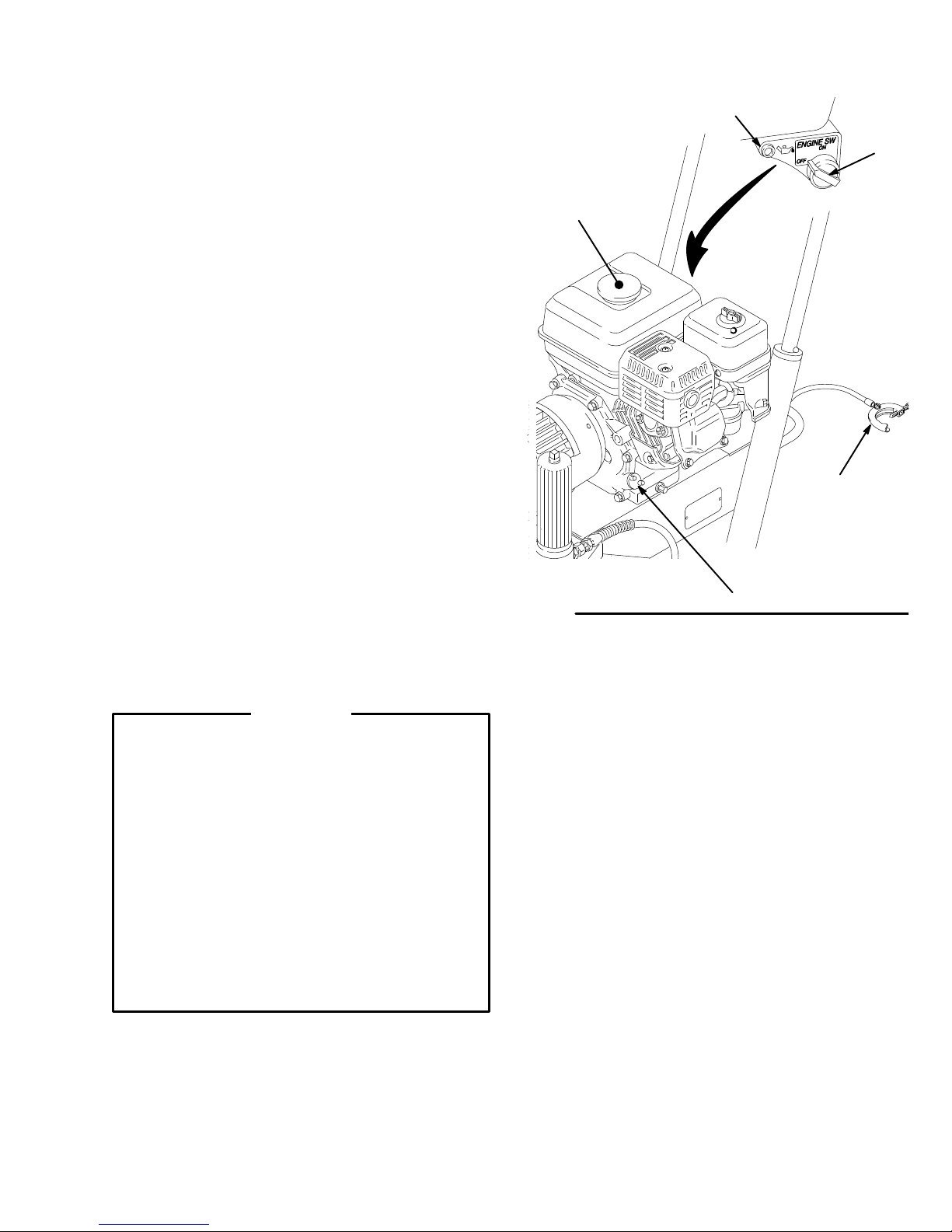
Fueling
WARNING
Gasoline is extremely flammable and explosive under
certain conditions.
Always shut of
Refuel in a well–ventilated area.
Do not smoke or allow flames or sparks in the area
where
the engine is refueled or where
stored.
Do not overfill the tank. Make sure the gas fill cap is
securely closed after refueling.
Be
careful not to spill fuel when fueling. Fuel vapor
spilled fuel can ignite. If any fuel is spilled, make sure
the
area is dry before starting the engine.
1. Fuel specifications. Use automotive gasoline with
a pump octane number [(R + M)/2] of 86 or higher,
or a research octane number of 91 or higher.
Unleaded fuel minimizes combustion chamber
deposits.
f the engine before refueling.
the gasoline is
or
2. Gasolines containing alcohol (gasohol). Do not
use
gasohol which contains methanol, if the gasohol
does
not contain cosolvents and corrosion inhibitors
for
methanol. Even if it does contain such
do not use the gasohol if it contains more than 5%
methanol.
NOTE: The HONDA engine warranty does not cover
damage
cohol.
tion.
3. General. Do not use oil and gasoline mixtures or
4. Tank
5. Shut off the engine before refueling.
6. After refueling, tighten the fuel tank cap firmly.
resulting from the use of gasolines containing al
See the HONDA engine manual for more informa
contaminated gasoline. Avoid getting dirt, dust or
in the fuel tank.
water
Capacity. 0.95 gallons (3.6 liter). Always leave
at
least 1/2 in. at the top of the tank for expansion.
additives,
-
-
307-847 11
Page 12

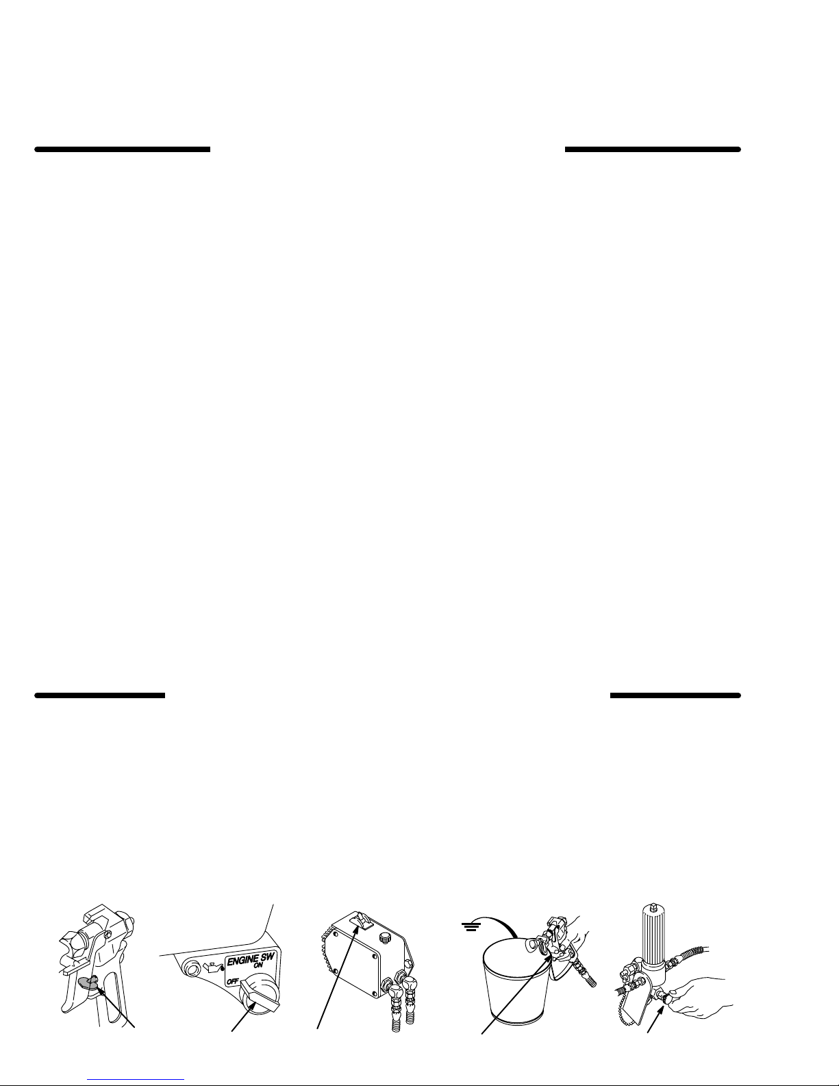
Startup
Before you start the sprayer
1. See Flushing
flush
the sprayer
Be sure the gas tank is full.
2.
3. Check the engine oil level.
NOTE: The
if it is low on oil. If you try to start it again without adding
more oil, a red light near the engine on/off switch glows
as
you pull the starter rope.
4. Be
sure the spark plug cable (G) is firmly pushed
onto the plug.
on page 15 to determine if you should
.
engine stops automatically
, or will not start,
Startup
NOTE:
1. When
2. If a secondary hose and gun is not installed, be
3. Place the suction tube into the paint, water or
4. Open the black fuel shutoff lever (H) by pushing
Refer to Fig. 4 as you start the sprayer
starting a sprayer that IS
move
the spray tip.
the cap (56) is securely plugging the secondary
sure
outlet
fitting.
solvent container, depending on whether you are
flushing
it
or are ready to spray
in the direction of the arrow
NOT PRIMED,
.
.
.
re
CAUTION
Never try to start the engine unless fluid pressure is
relieved and the pressure control switch (A) is OFF.
Trying
to start the engine when it is pressurized could
damage
the recoil system.
f. Open
7. Disengage the trigger safety latch (N).
8. To start the pump:
a.
b. T
c. Turn
d. Close
e. Release the trigger. Engage the trigger safety
9. If
you have not primed the sprayer with paint
move
the trigger safety latch. Trigger the gun into the water/solvent pail just until paint appears. Release the
trigger and engage the trigger safety latch. Repeat
for
the second gun if two guns are used.
the choke as soon as the engine starts, ex
cept in cold weather. In cold weather, leave the
choke
closed for 10 to 30
it to keep the engine running.
ing
Open the pressure drain valve (53).
urn the pressure control switch (A) to ON.
the pressure control knob (B) about 1/4 turn
from minimum pressure. Run the pump until
is flowing smoothly from the pressure drain
valve,
indicating the pump is fully primed.
the pressure drain valve (53). Hold a metal
part of the gun firmly against a grounded metal
pail
and squeeze the trigger until
the
gun.
latch (N).
the suction tube
to the paint container
seconds before open
fluid flows from
WARNING
To
reduce the risk of serious injury from fluid injection,
NEVER operate the spray gun with the tip guard removed.
10. Install the spray tip in the gun. See the separate
instruction manual, 307–848, supplied.
tip
-
-
fluid
yet,
. Release
5. Turn the pressure control switch (A) to OFF.
6. To start the engine:
a. Turn
b. Slide the metal throttle lever (K) away from the
c. If
d. T
the pressure adjusting knob (B) fully coun
terclockwise
fuel
tank to maximum position (fully left).
the engine is cold, close the
the
gray lever (J).
If
the engine is warm, close the
the
gray lever only half way or not at all.
urn the engine switch (L) to ON.
to the lowest pressure setting.
choke by moving
choke by moving
WARNING
A
rope which recoils too quickly may hit someone and
cause
serious injury
assembly.
e. Hold
the frame of the sprayer with one hand
pull
the starter rope rapidly
holding
turn
the rope until the engine starts.
307-84712
. The rope
the rope as you let it return.
could also jam in recoil
and firmly
and
. Continue
Pull and re
-
-
11. Adjust
lease
test paper to check the spray pattern and atomization. Turn the pressure adjusting knob (B) until you
get
setting
pattern.
the engine speed and pump pressure.
the trigger safety latch (N). T
a good pattern. Then slowly lower the throttle (K)
as far as you
can without changing the spray
rigger the gun onto
CAUTION
Always
lowest needed throttle setting, to increase the life of
the sprayer. Higher settings cause excessive clutch
cycling
use the lowest needed fluid pressure and
and premature tip and pump wear
.
CAUTION
Close the black fuel shutoff lever (H) whenever you
are transporting the sprayer to prevent fuel from
flooding
Keep
and
from leaking into the combustion chamber, which
makes
the engine.
the sprayer upright
when transporting it. This prevents crankcase oil
startup very dif
and level when operating it
ficult.
Re
the
-
Page 13

A
B
C
202
0138
28
56
51
D
M
L
0015
4
K
J
0016
H
47
0136
G
F
E
53
KEY
A Pressure
switch
B
Pressure adjusting knob
C
Air cleaner
D
Fuel T
E Muffler
F Engine
G
Spark plug cable
H
Fuel shutof
J Choke
K Throttle
L
Engine ON/OFF switch
M
Engine oil light
NT
(shown engaged)
4 Clutch
28
Displacement pump
47
Grounding wire and clamp
51
Fluid filter
53
Pressure drain valve
56 Secondary
202 Main
203
Whip end hose
204 “Contractor”
IV Dripless tip guard and
517 size SwitchT
Control ON/OFF
ank
f lever
rigger safety latch
hose outlet cap
hose
gun with RAC
ip
Fig. 4
203
204
N
0137
307-847 13
Page 14
Maintenance
WARNING
To
reduce the risk of
jection
or splashing in the eyes or on the skin, or injury
from moving parts, always follow the Pressure Re-
lief Procedure Warning, below, before checking,
adjusting,
connect
DAILY: Check
DAILY: Check
AFTER THE FIRST 20 HOURS OF OPERA
Drain the oil and refill with clean oil.
WEEKLY:
the
element.
ing in an unusually dusty environment, check the filter
daily
Replacement
HONDA
cleaning or
the spark plug!
Remove the cover of the air
Replace the element, if necessary
and replace it, if necessary
elements can be purchased from your
dealer
.
serious injury
shutting down the sprayer
the engine oil level and
and fill the gas tank.
, including fluid in
.
-
.
Dis-
fill as necessary
TION
filter and clean
. If operat
local
WARNING
Pressure Relief Procedure
To
reduce the
tion,
splashing fluid or solvent in the eyes or on the skin,
or injury from moving parts or electric shock, always fol
low this procedure whenever you shut off the sprayer,
when checking or servicing any part of the spray system, when installing, cleaning or changing spray tips,
and
whenever you stop spraying.
risk of serious injury
, including fluid injec
CAUTION
For
detailed engine maintenance and specifications,
refer
to the separate engine manual, supplied.
.
WEEKLY: Check the level of the TSL in the displacement pump packing nut. Fill the nut, if necessary. Keep
TSL
in the nut to help lubricate the pump packings.
AFTER EACH 100 HOURS OF OPERA
Change the oil.
-
SPARK
plug.
Use a spark plug wrench when installing and removing
the
4. Disengage
-
-
5.
6. Open the pressure drain valve. Leave the valve
7.
PLUG:
Gap the plug to 0.025 to 0.030 in. (0.7 to 0.8
plug.
of
the gun firmly to the side of a grounded metal pail,
and
trigger the gun to relieve pressure.
Engage the trigger safety latch.
open
until you are ready to spray again.
Disconnect the spark plug cable.
Use only an (NGK)
the trigger safety latch. Hold
TION:
BP6ES or BPR6ES
mm).
a metal part
1.
Engage the trigger safety latch.
2. T
urn the engine ON/OFF switch to OFF
3. T
urn the pressure control switch to OFF
1,5 2 3
If you suspect that the spray tip or hose is completely
clogged,
.
.
ter following the steps above,
the tip guard retaining nut or hose end coupling to relieve pressure gradually, then loosen completely. Now
clear
or that pressure has not been fully relieved af
VERY SLOWLY loosen
the tip or hose.
4
6
-
0139
307-84714
Page 15
Flushing
2
When to Flush
1. New Sprayer. This unit was factory tested in lightweight
oil, which was left in to protect the pump.
Before using water–base paint,
flush with mineral
spirits, followed by a soapy water flush, and then a
clean
water flush.
Before using oil–base paint,
flush with mineral spir-
its.
2. Changing Colors.
as mineral spirits or water
such
3. Changing from water–base to oil–base paint.
with
warm, soapy water, then mineral spirits.
Flush with a compatible solvent
.
Flush
4. Changing from oil–base to water–base paint. Flush
with
mineral spirits, followed by warm, soapy water
and then a clean water flush.
CAUTION
NEVER leave water in the sprayer if there is the
slightest chance it could freeze. Push the water out
with
mineral
trol tube prevents the sprayer from being started, and
causes
spirits. W
ater frozen in the pressure con
serious damage to the pressure control.
-
WARNING
To reduce the risk of static sparking and splashing
when
flushing, always remove the spray tip from the
gun,
and hold a metal part of the gun firmly to the
of,
and aimed into, a grounded metal pail .
Maintain
metal-to-metal
contact when
flushing
,
6. Follow Startup
until clean solvent comes from the nozzle. Release
the
trigger and engage the trigger safety latch.
NOTE: For
two guns, release the trigger
the second gun and trigger that gun until clean solvent
comes from the nozzle. Flush the first gun and then the
second
gun at least one more time.
on page 12. Keep the gun triggered
safety latch on
side
firm
5. Storage.
Water
base paint:
its and leave
flush with water
the
pump, hose and gun filled with min
, then mineral spir
eral spirits. Shut off the sprayer, remove the spark
plug
cable, and open the pressure drain
lieve
pressure. Leave the drain valve open.
Oil
base paint:
flush with mineral spirits and leave
valve to re
pump, hose and gun filled with mineral spirits. Shut
off the sprayer, remove the spark plug cable, and
open the pressure drain valve to relieve pressure.
Leave
the drain valve open.
6.
Startup after storage.
Before using water–base paint
spirits
with soapy water
, and then with clean water
When using oil–based paint,
spirits
with the paint to be sprayed.
, flush out mineral
flush out the mineral
How to Flush
NOTE: “Solvent”
1.
Relieve pressure. See page 14.
refers to water or oil-based solvent.
the
7. Check all fluid connections for leaks. Relieve pres-
sure before tightening any connections. Start the
-
-
sprayer.
8. Remove the suction tube from the solvent pail. Dis-
Recheck the connections for leaks.
engage the trigger safety latch. Trigger the gun to
-
force
solvent from the hose. Do not let the pump run
dry
for more than 30 seconds, to avoid damaging
pump
packings. Relieve pressure.
9. Remove
the strainer
, suction tube and suction
and clean them separately to be sure all paint sediment is removed. Dried paint can build up in these
parts
and later cause performance problems.
10. Unscrew the filter bowl and reinstall the clean
screen.
Reinstall the bowl, hand tight only
.
11. Follow Storage or Changing Colors, to the left. Relieve
pressure.
R
S
the
hose
.
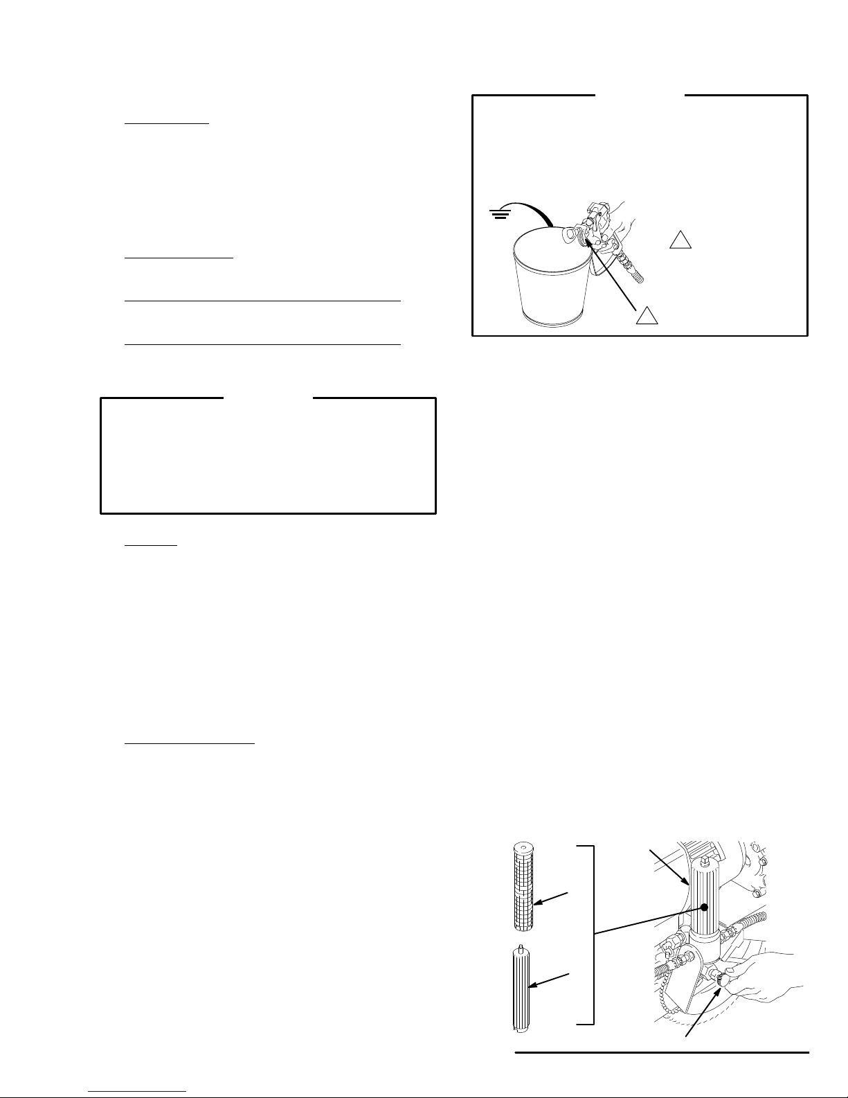
2. Remove the filter bowl (R) and screen (S); see instruction
manual 307–273, supplied. Install the bowl
and support (T), without the screen, to flush. Clean
the
screen separately
3.
Close the pressure drain valve (53).
4.
Put the suction tube in a grounded pail of solvent.
5.
Remove the spray tip from the gun(s).
. See Fig. 5.
T
Fig. 5
53
014
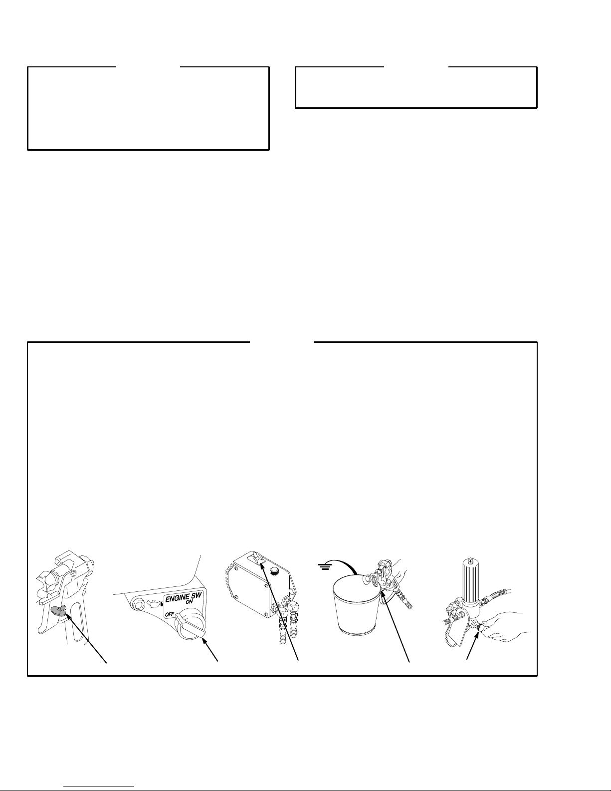
Page 16

Troubleshooting
WARNING
Pressure
To
reduce the risk of serious injury, including fluid injec
tion,
moving parts, always follow this procedure when you
shut
ing
Relief Procedure
splashing in the eyes or on the skin, or injury from
of
f the sprayer
the system, and when changing spray tips.
Engage the trigger safety latch.
T
urn the engine ON/OFF switch to OFF
T
urn the pressure control switch to OFF
, when checking, adjusting or clean
.
.
Guide
Disengage the trigger safety latch. Hold a metal
-
-
part of the gun firmly to the side of a grounded
metal pail, and trigger the gun.
Engage the trigger safety latch.
Open the fluid pressure drain valve and leave it
open until you start the sprayer again.
Disconnect the spark plug.
If you suspect the hose or spray tip is completely
clogged
ing the steps above, VERY SLOWLY
guard
ly.
or that pressure is not fully
or hose end coupling to
Now clear the tip or hose obstruction.
relieved after follow
relieve pressure gradual
loosen the tip
-
-
Check everything in the chart before disassembling the sprayer
PROBLEM CAUSE SOLUTION
Engine/sprayer won’t start
Engine won’t “pull over”
Engine operates, but displace
ment pump doesn’t
Engine switch not on
Out of gas
Engine oil level low
Spark plug cable disconnected or
spark plug damaged
W
ater frozen in pressure control
Oil seepage into combustion
chamber
-
Pressure control switch turned OFFTurn on.
Pressure setting too low
Displacement pump outlet filter dirty
.
T
urn on.
Replenish
T
ry starting engine. If light on rear of en
gine glows, replenish oil.
Connect cable on top of engine or replace
spark plug.
Return pressure control to authorized
Graco dealer for repair
Remove spark plug. Pull starter rope 3 or
4 times. Clean or replace plug. T
start. Keep sprayer upright to avoid oil
seepage.
Increase pressure.
Clean filter
-
.
ry to
.
T
ip or tip filter clogged
Displacement pump rod seized by
dry paint
Connecting rod worn or damaged
Drive housing worn or damaged
Electrical power not energizing field
Clutch worn or damaged
Pinion assembly worn or damaged
Clean tip or tip filter
Service pump. See page .
Replace. See page 18.
Replace. See page 19.
Check wiring connections. See Fig. 13,
page 23.
With pressure control switch ON and
pressure turned to MAXIMUM, use a test
light to check for power at black and white
wires from pressure control.
Have pressure control checked by autho
rized Graco dealer
Service. See page 22.
Service. See page 20.
.
.
-
Page 17

PROBLEM
CAUSE SOLUTION
Displacement pump output
low on upstroke
Displacement pump output
low on downstroke or both
strokes
Paint leaks into wet–cup
Pump inlet screen clogged
Piston ball check not seating
Piston packings worn or damaged
Sleeve gasket in displacement
pump worn or damaged
Pump inlet screen clogged
Piston packings worn or damaged
Intake valve ball check not seating
properly
Engine RPM too low
Clutch worn or damaged
Loose wet–cup
Throat packings worn or damaged
Displacement rod worn or damaged
Clean.
Service piston ball check. See page 31.
Replace packings. See page 31.
Replace. See page 31.
Clean.
Replace packings. See page 31.
Clean and service. See page 31.
Increase throttle setting. See
Step 1
1, page 12.
Startup,
Replace. See page 22.
T
ighten just enough to stop leakage.
Replace packings. See page 31.
Replace rod. See page 31.
Low fluid delivery
Pump inlet screen clogged.
Pressure setting too low
Engine RPM too low
Dirty outlet filter
, tip filter or tip
Large pressure drop in hose
Clean.
Increase pressure. See
Step 1
1, page 12.
Startup,
Increase throttle setting. See
Step 1
1, page 12.
Clean.
Use larger diameter hose.
Startup,
Spitting from gun Air in fluid pump or hose Check for loose connections at pump in
take and tighten. Then prime the pump.
See page 12.
T
ip partially clogged
Fluid supply is low or empty Refill and prime the pump. See
Clear.
Startup,
page 12. Check fluid supply often to pre
Pump is dif
ficult to prime
Air leak
vent running the pump dry
Check all hose connections and tighten as
.
needed.
Reduce RPM and cycle pump as slowly
as possible during priming.
Intake valve is leaking
Shut of
f pump and relieve pressure. Dis
assemble and clean intake valve. Be sure
ball seat is not nicked or worn and that the
ball seats well. Reassemble.
-
-
-
W
orn packings
Fluid is too thick
Repack the pump. See page 31.
Thin fluid according to supplier
recommendations.
307-847 17
’s
Page 18

Bearing
Housing & Connecting Rod
WARNING
To
reduce the risk of
jection
always follow the
Warning on page 14 before checking, adjusting,
cleaning or shutting off the sprayer.
spark
plug!
NOTE:
1.
2. For upright models only: Remove the spring clips
3. Disconnect the pump outlet hose (59) from the dis-
4. Use
5. Loosen the jam nut (27) with an adjustable wrench.
6. Use a hex key wrench to remove the four screws (73)
7. While
8. Inspect
9. Evenly
10. Assemble
Steps 1 to 13 refer to Fig. 6.
Remove the front cover and screws (23,68).
(112, 114) and the drain hose (113). Unscrew the
suction
the pump intake valve (B) to keep the pump from
loosening.
placement
(26)
rear.
Unscrew
and
lightly
with
ing
rod
parts
in
necting
ally
assembly
ing (21).
tube (30) from the pump, holding a wrench on
pump outlet nipple (92).
a screwdriver to push aside the retaining
at the top of the pump. Push the pin (25) out the
and remove the displacement pump.
lockwashers (74) from the bearing housing (21).
pulling the connecting rod (22) with one
tap the lower rear of the
a plastic mallet to loosen it from the drive hous
(20). Pull the bearing housing and the connecting
assembly (22) of
the crank (A) for excessive
as needed.
lubricate the inside of the bronze bearing
the bearing housing (21), and the inside of the con
rod link (D),
pack the roller bearing (E) in the connecting
(22) with bearing grease.
the connecting rod (22)
serious injury
Pressure Relief Procedure
, including fluid in
Disconnect the
spring
hand,
bearing housing (21)
f the drive housing.
wear and replace
(C)
with high–quality motor oil. Liber
rod
and bearing hous
-
-
-
-
-
CAUTION
DO
NOT use the bearing housing screw (73) to align
or seat the bearing housing with the drive housing.
These parts must be aligned using the locating pins
(F),
to help avoid premature bearing wear
13. Install the screws (73) and lockwashers (74) on the
bearing housing. Tighten evenly to 300 in–lb (34
N.m).
14. Refer
to
Installing the Pump
C
68
Torque
300 in–lb
(34 N.m)
74
73
23
to
25
22
27
on page 31.
20
A
E
D
B
.
F
21
26
59
92
112
113
11. Clean the mating surfaces of the bearing and drive
housings.
12. Align
the connecting rod with the crank (A) and care
fully align the locating pins (F) in the drive housing
(20)
with the holes in the bearing housing (21). Push
the bearing housing onto the drive housing or tap it
into
place with a plastic mallet.
307-84718
-
Fig. 6
30
114
0149
Page 19

Drive
Housing
WARNING
To
reduce the risk of
jection
always follow the
Warning on page 14 before checking, adjusting,
cleaning or shutting off the sprayer.
spark
plug!
NOTE:
1.
2. Disconnect
3. Remove the four screws (73) and lockwashers (74)
4. Lightly
5. Remove the two screws (24)
6. Lightly tap around the drive housing (20) to loosen
Refer to Fig. 7 for this procedure.
Remove the front cover and screws (23,68).
ment
pump
the spring clips (112, 114) and the drain hose (113)
from
the pump.
from
the bearing housing (20).
tap the back of the bearing
a plastic mallet. Pull the pump, bearing housing and
connecting rod away from the drive housing as one
assembly.
Remove
the drive housing. Pull the drive housing straight off
the
cluster
the four screws (10) and lockwashers (1
pinion housing. Be prepared to support the gear
(18), which may also come out.
serious injury
Pressure Relief Procedure
, including fluid in
-
Disconnect the
the pump outlet hose from the displace
nipple. For the upright carts only
housing (21) with
and lockwashers (1
, remove
1).
1).
20a
CAUTION
DO NOT drop the gear cluster (18) when removing
the
drive housing (20). The gear cluster is easily dam
aged.
The gear may stay engaged in the drive hous
or pinion housing.
ing
DO
NOT lose the thrust balls
each
end of the gear cluster
tween the gears. The ball, which is heavily covered
with grease, usually stays in the shaft recesses, but
could be dislodged. If the balls are caught between
-
20b
the gears and not removed, they
age
the drive housing. If the balls are not in place, the
bearings
7. Liberally apply bearing grease to the gear cluster
8.
9. Starting at Step 4, work backwards to reassemble
will wear prematurely
(18).
A tube
ment gear cluster. Use a full 6 oz. (160 grams) of
grease.
place.
Place the bronze colored washer (20a)
silver–colored washer (20b) on the shaft protruding
from
the big bearing of the drive housing (20). Align
the gears and push the new drive housing straight
onto
the pinion housing and locating pins (B).
the sprayer. Or, move ahead to the next section in
this
manual if further service is needed.
19
of grease is supplied with each replace
Be sure the thrust balls (20c and 19d) are in
10
B
11
(20c or 19d) located at
, or allow them to fall be
will seriously dam
.
-
-
-
-
-
and then the
21
74
73
23
68
Fig. 7
20
11
24
10
11
19d
18
20c
112
113
114
0170
Page 20

Pinion,
Clutch, Clamp, Field & Engine
Disassembling these parts can start from the pinion
housing,
needed.
or from the clutch if no pinion service is
Pinion
Pinion Housing
WARNING
To
reduce the risk of
jection
always follow the
Warning on page 14 before checking, adjusting,
cleaning or shutting off the sprayer.
spark
plug!
NOTE:
1.
Refer to Fig. 8 for Steps 1 to 3.
Remove the two bottom screws (10) and lockwash
ers (11) first, and then remove the top three screws
(10)
and lockwashers (1
serious injury
Pressure Relief Procedure
1).
, including fluid in
Disconnect the
-
starting from the pinion housing, first follow Steps 1 to
If
6
of
Drive Housing
the
procedure below
If starting from the clutch
2. Pull
3. Pull the armature (4a) off the hub (19j –
the pinion housing away from
The
armature (4a) will come with it.
of
the pinion housing.
, on page
.
, see page 22.
19, and then continue with
the clutch housing.
CAUTION
Do not lose the thrust ball (19d). Refer to the CAUTION
on page 19 for more information.
NOTE: To
-
assemble more of the sprayer, go to page 22. To reassemble
sembly,
disassemble the
the sprayer from this point, skip ahead to
page 27, Step 7.
pinion, go to page 21. T
see Fig. 9)
o dis
Reas-
-
Fig. 8
See
page 21
10
11
2
4a
19
19d
10
11
0171
Page 21

Pinion
Housing
1
Lubricate exterior
2
Lubricate inner and outer diameters
3
Lubricate teeth
CUTAWAY
PINION HOUSING (19a)
Fig.
VIEW OF
0041
9
5
4
19c
1
19d
4
Press pinion assembly in here
5
Back of pinion housing (19a)
**Included in Repair Kit 221–032
19e
19b
1
19a
Repairing the Pinion
NOTE: Refer
NOTE: A
pinion parts individually.Otherwise, use Repair Kit No.
221–032,
sembled
to Fig. 9 except where noted.
hydraulic press is required if you purchase the
which includes the shaft and bearings pre–as
and lubricated.
19k
19h**
19g**
19f**
3
2
If purchasing parts separately, use these instructions.
Disassemble as far as needed for the parts being
replaced.
-
NOTE: The
when
remove
old
bearings (19h and 19f) will be damaged
removed. Have extra
them for any reason.
ones on hand if you need to
19m**
19j**
2
0169
If using Repair Kit 221–032, follow Steps 1 to 5, below
1. Remove
the small ring (19m**) from the hub (19j) and
the large ring (19k) from the bearing recess of the
pinion
housing (19a).
2. Push on the front of the shaft (19g**) to force the
bearing
and hub assembly out of the housing (19a).
3. Install the new shaft assembly into the pinion housing,
pushing it to the shoulder of the housing (19a).
4.
Install the rings (19k and 19m**).
5. Go
to
Reassembly
, 27, Step 7, or continue on page
22.
Round bar to push
1
on shaft (19g)
2
Hydraulic press
T
wo steel bars (
3
front bar not shown)
T
wo steel bars
4
Press platform
5
Placement
pressing off large bearing (19h)
1
19h
of steel blocks when
2
19j
3
4
.
1.
Remove the small ring (19m) from the hub (19j).
2. Remove
of
3. Push
ing
4.
Using a hydraulic press,
stock
the snap ring (19k) from the bearing recess
the pinion housing (19a).
on the front of the shaft (19g) to force the bear
(19h) and hub (19j) assembly out of the housing.
place pieces of steel bar
on the inner race of the large bearing (19h) and
press the shaft through the hub and bearing. Then
turn over the shaft and press out the small bearing
(19f).
See Fig. 10.
5.
Apply lubricant to the parts as shown in Fig. 9.
6. Press fit the following parts: Large bearing (19h) to
large shoulder of the shaft (19g).
the
Small
(19f) to the shoulder of the shaft (19g). Hub (19j)
onto the shaft (19g) all the way to the large bearing
(19h).
7. Install
the shaft assembly
of
the housing (19a).
, pushing it
to the shoulder
-
bearing
Fig.
10
8. Install the snap ring (19k). Install the small ring
(19m).
5
0043
9. Go
to
22.
Reassembly
, 27, Step 7, or continue on page
307-847 21
Page 22

Clutch
NOTE: The clutch assembly (4) includes the armature
(4a) and rotor (4b). The armature and rotor must be replaced
together so they wear evenly
.
NOTE: If the pinion assembly (19) is not yet separated
from the clutch housing (2), follow Steps 1 to 4. Otherwise,
start at Step 5.
NOTE:
1. Follow
Refer to Fig. 1
the
page
14.
1 for this procedure.
Pressure Relief Procedure W
arning
on
2. Disconnect the hose (59) from the displacement
pump. For the upright cart only
12, 1
clips (1
14) and drain hose (1
, remove the spring
13).
3. Remove the bottom two screws and lockwashers
(10, 11) from the front of the clutch housing (2) and
then
the remaining three of them.
4. Tap lightly on the back of the bearing housing (21)
a plastic
with
the
clutch housing. Pull the assembly away
mallet to loosen the assembly (D) from
.
4b
11
16
4a
5. The armature (4a) was removed with the pinion
housing.
6. There
Remove the armature from the pinion
are two ways to remove the rotor (4b).
a. Remove the four socket head capscrews (16)
and lockwashers (11). Install two of the screws
in the threaded holes in the rotor. Alternately
tighten
the screws until the rotor comes off. See
Fig. 11.
b. You
can use a standard steering
However
are also needed.
steering
, two 1/4–22– x 3
Replace
wheel puller with the longer screws (B).
wheel puller (A).
or
4 in. long screws (B)
the short screws of the
Turn the screws (B) into the threaded holes of
the rotor (4b). Tighten the capscrew (C) of the
tool
7. Skip
tinue
until the rotor comes of
ahead to
Reassembly, page 27, Step 6, or con
on the next page.
f. See Fig. 1
10
11
2
hub.
1.
-
1
2
Fig. 11
Threaded holes
Pinion
shaft located
in back
D
1
2
19
A
B
C
59
Using
112
a steering wheel
puller to remove rotor
113
114
Page 23

Engine
NOTE: The engine must be removed before the Field,
Clamp
and Clutch Housing can be removed.
1. Working
under the mounting plate
(A) of the cart, re
move the screw (15), lockwasher (80) and washer
(99)
which
hold the clutch housing (2) to the cart. See
Fig.
13.
2. Still working under the mounting plate, remove the
locknuts (111) and then pull the screws (14)
two
out
of the base of the engine. Disconnect the red wire
from the engine lead (B). Disconnect the black and
white wires from the field. For the upright cart only
loosen the clamp (97). Pull the wires carefully
through
gine.
3. Lift
4. Remove
Clutch
5. Skip
the grommets (66) before removing the en
See Fig. 12 and 13.
the
engine carefully and place it on a work bench.
the
Field
Housing
ahead to
and W
, as instructed
Reassembly, page 27, Step 5.
iring Harness, Clamp
on pages 24 and 25.
and
NOTE: All service to the engine must be performed by
an
authorized HONDA dealer
.
-
,
10
11
-
2
66
A
62,9,61
97
WHITE
BLACK
Fig. 13
View
from under engine mounting
plate on upright cart
66
1
66
2
RED
99
80
15
Fig. 12
o field
T
1
2
T
o engine
66
1
66
WHITE
BLACK
V
iew from under engine mounting
0154 0147
plate on lo-boy cart
B
111
97
2
RED
Page 24

Field
and W
iring Harness
NOTE: Refer
1.
Remove the engine from the cart. See page 23.
2. Pull the plastic caps (B) off the wire screws (98) in
both places on the field. Loosen the screws and release
6
to Fig. 14.
the wires (96).
12
2
3. Loosen the four setscrews (12) holding the field (6)
to
the clutch housing (2).
4.
Pull of
f the field.
5. Skip
ahead to
tinue
on page 25.
Reassembly, page 26, Step
4 or con
-
B
98
Fig. 14
96
0046
Page 25

Clamp
NOTE: A
x
3 or 4 in. long screws are required to remove the
NOTE: Refer
1. Loosen
2. Install two screws (B) of the tool (A) in two of the
3. Skip
standard steering wheel puller and two 1/4–28
clamp.
to Fig. 15.
the two screws (16) on the clamp (3), work
ing
through the slot at the bottom of the clutch hous
ing (2).
threaded holes in the clamp (3). Tighten the screw
(C)
until the clamp comes of
ahead to
tinue
to the right.
Reassembly, page 26, Step 3, or con
f.
-
-
2
A
B
C
Fig. 15
3
16
0155
Clutch
NOTE: Refer
1. Remove
which
2. Remove the capscrew (15), lockwasher (80) and
washer
3.
Remove the engine key (13).
4.
Pull of
5.
Skip ahead to
to Fig. 16.
the four capscrews (8) and lockwashers (9)
hold the clutch housing (2) to the engine.
(99) from beneath the mounting plate (D).
f the clutch housing (2).
Reassembly, page 26, Step 1.
Housing
2
9
8
Fig. 16
13
D
99
80
15
0156
Page 26

Reassembly
9
1. Install the clutch housing (2), capscrews (8) and
lockwashers
2.
Install the engine shaft
3. Press
the
1.99 in.
Fig.
18.
To check the dimension, place a rigid, straight steel
bar
(B) across the face of the clutch housing (2). Use
an accurate measuring device to measure the distance
between the bar and the face of the clamp. Ad
the clamp as necessary
just
(16)
to 120 in–lb (14 N.m).
4. Install
through the slot in the clutch housing, connect the
wires of the harness (96) to the screws (98) in both
places on the field. Pull the plastic caps (C) up and
snap
them over the screws. With
in
the field and the clutch housing (2) aligned, tighten
the
setscrews (12) oppositely
(3.2
N.m). See Fig. 17.
Torque
1
and evenly to
27 in–lb (3.2 N.m)
2
Slot
(9) on the engine. See Fig. 17.
the clamp (3)
key (13).
onto the engine shaft. Maintain
See Fig. 17.
+/– 0.01 (50.55 mm) dimension shown in
. T
orque the two screws
the
field
(6)
in the clutch housing (2). W
the setscrew holes
and evenly
oppositely
, to 27 in–lb
13
orking
2
1
3
B
Face of housing
-
1
2
3
Fig.
T
orque to
120 in–lb
(14 N.m)
1.99”
(50.55 mm)
18
16
2
0050
3
Fig. 17
1
12
9
8
A
2
2
16
6
96
98
004
Page 27

Reassembly
5. Place
the
mounting
engine (1)
assembly on the cart. Align the
holes. Carefully guide the engine wire
and wiring harness (96) from the field, through the
appropriate
grommets (66)
in the mounting plate (E).
Install the flange screws (14) and locknuts (111).
Torque to 15 ft–lb (20.4 N.m). Install the capscrew
(15), lockwasher (80) and washer (99) from under
the
engine mounting plate to the clutch housing
Connect
nect
drawing
6. Be
the engine wire (D) to the red wire, and con
the black and
white wires as shown in the Detail
in Fig. 19.
sure the face of the
rotor (4b)
and the
field is free
of all oil and contaminants. Remove any burrs on the
outside
ers (11) and capscrews (16). T
edge of the rotor
. Install the rotor
orque the capscrews
, lockwash
to 7 ft–lb (9.5 N.m). See Fig. 19.
After installing the rotor (4b), check the clearance-
between
1
2
3
4
5
6
the outside diameter of the rotor and the in
T
orque to 7 ft–lb 99.5 N.m)
Spline
Face must be clean
T
orque to 15 ft–lb (20.4 N.m)
o field (ref. 96)
T
T
o engine (ref. D)
2
4a
1
16
11
(D)
(2).
4b
side
diameter of the field. The clearance must be at
least 0.010 in. (0.25 mm) all the way around. Use
shim
stock or feeler gauge. If necessary
setscrews (12) and reposition the field. Tighten the
setscrews
evenly to 27 in–lb (3.2 N.m).
Be sure the face of the armature (4a) is clean. Assemble
-
ing
makes
the armature to the shaft in
(19). A retaining ring located within the armature
it dif
ficult to assemble these parts. Follow this
the pinion hous
procedure for the best results. First, engage a few
splines
screwdriver
armature,
-
armature onto the shaft until it contacts the ring
(19m).
of both
parts. While they are engaged, use a
to gently push the retaining ring into the
and finish engaging the splines. Push the
See Fig. 19.
7. Assemble the pinion housing (19) to the clutch
housing,
-
(11).
using the capscrews (10) and
See Fig. 19.
1
12
10
11
2
14
, loosen
the
lockwashers
4
-
View
from under engine mounting plate on Lo–Boy cart
66
WHITE
Fig. 19
BLACK
6
3
96
99
E
D
80
15
111
19
0157
V
iew from under engine mounting plate on upright cart
66
5
97
6
RED
WHITE
BLACK
5
Ref 14,1
6
RED
11
014601460147
Page 28

Pressure
Control Replacement
WARNING
To
reduce the risk of
jection
always follow the
serious injury
, including fluid in
Pressure Relief Procedure
Warning on page 14 before checking, adjusting,
cleaning or shutting off the sprayer.
spark
plug!
1.
Disconnect both hoses at the pressure control (63).
while
holding the elbows (317 or 320)
CAUTION,
hose
end
of this procedure. See Fig. 20.
below
. Note the original
to be sure you
reassemble them correctly at the
Disconnect the
firmly
. See the
location of each
CAUTION
DO NOT allow the elbow (317 or 320) to turn when
removing or connecting the hoses. Turning the elbows
can damage the sensitive bourdon tube.
106
76
62
317
63
67
64
2. Working
-
disconnect
For
under the engine mounting plate of the cart,
the red, black and white wires.
the upright cart
, remove the three
nuts (61) and
lockwashers (9) from the capscrews (62). See Fig.
21.
For
the lo-boy cart
washers
(9). See Fig. 21.
, remove the three screws (62) and
3. Remove the wire clamp (97). See Fig. 21. Remove
the
pressure control.
4. Remove the pressure control cover (76) and the
mounting
bracket (67 or 107). See Fig. 20.
106
76
63
64
319
107
66
316
Fig. 20
WHITE
BLACK
66
1
320
1
2
o pump
T
1
2
T
o filter
UPRIGHT
CART
0144 0145
o field
T
1
2
T
o engine
2
1
1
2
9
62
LO-BOY CART
66
97
2
61,9,62
RED
97
66
WHITE
RED
BLACK
View
from under engine mounting
Fig.
21
plate on upright cart
0146
V
iew from under engine mounting
plate on lo-boy cart
0147
Page 29

Pressure
Control Replacement
5. Disconnect the black, red and white wires from the
rectifier
with
6. Unscrew
box,
7. For
elbow
(307) and switch (302),
which are sheathed
the conductor (314). See Fig. 22.
the connector (318 or 108) from the control
pulling the conductor and wires out with it.
the upright
cart
, remove the nipple (316) from the
(317). See Fig. 22.
8. Use a wrench to hold the hex of the adapters (A)
while
removing the elbows (317, or 320 and 319).
9.
Reassemble in the reverse order
.
For Upright cart sprayers
307
302
RED
RED
h
10. For
wires
the upright carts
through the wire clamps (97).
, guide the new pressure control
Fasten the wire
clamps to the cart with the same screws, lockwashers,
(76)
11. For
and nuts (61, 9, 62) which hold the bracket
to the cart. See Fig. 20.
the lo-boy carts
, guide the pressure control wires
through the single wire clamp (97), and install the
screws
to
and washers (62, 9) to hold the bracket (107)
the cart. See Fig. 20.
12. Perform the Pressure Control Adjustment on
30 before regular operation of the sprayer
page
.
A
317
316
-
WHITE
BLACK
For
Lo-Boy cart sprayers
RED
RED
315,305
302
314
307
318
313
RED
GROUND
107
108
A
0150
Ref 320
Top
Rectifier
view
0151
(307) connections
0148
320
319
315,305
Fig.
22
BLACK
WHITE
313
RED
GROUND
0165
Page 30

Pressure
Control Adjustment
WARNING
USE
EXTREME CAUTION WHEN PERFORMING THIS CALIBRA
fluid injection injury or other serious injury
sion or moving parts.
This procedure sets the sprayer to 2600–3000 psi
(182–210
This
bar) MAXIMUM WORKING PRESSURE.
procedure must be performed when the pressure
control assembly is removed and reinstalled, or replaced,
to be sure the sprayer is properly calibrated.
Improper calibration can cause the sprayer to over–
pressurize
plosion.
and result in component rupture, fire or
It may also prevent the sprayer from
the maximum working pressure, resulting in poor
sprayer
NEVER
performance.
attempt
to increase the fluid outlet pressure by
performing these calibrations in any other way.
, which can result from component rupture, electric shock, fire, explo
ex
-
obtaining
TION PROCEDURE to reduce the risk of a
-
NEVER EXCEED 3000 psi (210 bar) MAXIMUM
WORKING PRESSURE. Normal operation of the
sprayer
rupture,
ALWAYS
at higher pressures could result in component
fire or explosion.
use a
new
50 foot (15.2 m) spray hose, rated
for at least 3000 psi (210 bar) MAXIMUM WORKING
PRESSURE,
when performing this procedure. A
used,
under–rated hose could develop a high pressure leak
or rupture.
AVOID touching the wires in the pressure control assembly when the control box cover is removed, to reduce
the risk of electric shock.
Service Tools Needed
NEW 50 foot (15.2 m), 3000 psi (210 bar), flexible nylon,
airless spray hose, p/n 223–541
0–5000 psi (0–350 bar) fluid–filled pressure gauge, p/n
102–814
NEW
T
spray tip, size 0.025 to 0.029
3/8 in. ignition wrench or nut driver
5 gallon pail and water or mineral spirits
Swivel, p/n 156–823
Nipple, p/n 162–453
ee, p/n 104–984
Set Up
1. Follow
2.
the
Pressure Relief Procedure W
page
14.
Set up the system as shown in Fig. 23.
arning
on
Set the Dead Band (Pressure Differential)
NOTE: Do not alter this adjustment if the wheel is al-
ready
set as shown in Fig. 24.
1.
Remove the pressure control cover
2. Set the white differential wheel (A) on the microswitch.
T
urn the wheel so the letter F is concealed be
hind
the switch and the letter A is the
.
first letter seen.
b. Slowly tighten the nut just until another click is
heard.
ST
OP.
Replace the plug (326) and pressure control cover
4.
to
Connect
fluid outlet
102–814
104–984
162–453
223–541
Fig. 23
156–823
.
0474
A
-
Pressure Up
1. Start
2.
3. Shut off the engine. If the pressure drops, replace
Adjust the Pressure See
1.
2. Turn and hold the pressure control knob (B) at the
3. Engage
the sprayer and prime it.
Adjust the pressure to 2600 psi (180 bar).
pump
packings before proceeding. See page 31.
Fig. 25.
Remove the pressure control plug (326).
maximum
pressure setting.
the nut (C): insert the nut driver through the
pressure
the
a. Loosen
control
hole, or use the ignition wrench from
front of the pressure control.
the nut just until you hear a click. ST
OP.
Fig.
24
Fig. 25
0475
A
B
h
C
326
0151
Page 31

Removing
and Installing the Pump
WARNING
To
reduce the risk of
jection
always follow the
Warning on page 14 before checking, adjusting,
cleaning or shutting off the sprayer.
spark
plug!
Removing the pump See
1.
Flush the pump. Relieve pressure. See page 14.
2. Hold the intake valve (423) with a wrench and unscrew
the suction tube (30). Remove the hose
For upright carts, remove the spring clips (112,114)
and
drain hose (1
3.
Push the retaining spring (26) up. Push the pin (25)
out the rear
4. Loosen
low
the locknut (27). Unscrew the pump. See be
for how to repair the pump.
.
serious injury
Pressure Relief Procedure
, including fluid in
Disconnect the
Fig. 26.
13).
-
(59).
Installing the pump See
-
1. Screw
2.
3. Push
4. Install
1
2
the
pump about 3/4 of the way into the bearing
housing
the
pump
Back of
cylinder
and
way around the connecting rod. Tighten the locknut
(27)
wrench
outlet
carts,
Face
T
(21). Hold the pin (25) up to the pin hole on
connecting rod (22) and continue screwing in
until the pin slides easily into the hole.
f the pump until the top threads of the pump
are flush with the
the outlet nipple faces back.
the retaining spring (26)
to 90 ft–lb (1
and a light hammer
the
front cover and screws. Connect the pump
hose. Install the suction tube parts. For Upright
install the spring clips and drain hose.
of bearing housing
orque to 90 ft–lb (1
Fig. 27.
the
face of the bearing housing
into the groove all the
10 N.m) using a 2 1/4 in. open end
.
10 N.m)
26
25
27
30
Fig. 26
59
112
113
114
0477
Displacement
Disassembly procedure
1. Remove
2.
Disassemble the intake valve. See Fig. 28.
3. Clean and inspect the parts. Replace any worn or
damaged parts. Use a new o–ring (401* ). If no further sevice is needed, reassemble the intake valve
and
the pump from the sprayer
torque
it into the cylinder to 1
. See above.
10 ft–lb (146 N.m).
25
22
26
1
Fig. 27
Pump Repair
to
Torque
1
1
10 ft–lb
(146 N.m)
*404
*401
27
419
420
421*
21
2
0031
Fig.
28
423
1
307-847 31
Page 32

Displacement
Pump Repair
4. To disassemble the rest of the pump, remove the
packing
5. Use
Pull
6.
Remove the throat packings. See Fig. 33.
nut (416) and plug (405). See Fig. 33.
a plastic mallet to tap the piston rod (424) down.
the rod out through the bottom of the cylinder
.
WARNING
Always use the special sleeve removal tool, P/N
220–991,
ods
ous
ing the tool, return the sleeve and cylinder to your
Graco
7. Remove the sleeve. Screw the large nut (B) of the
tool
rod
Fig.
8. Clamp
en
(422).
9.
Disassemble the piston valve (422). See Fig. 30.
to remove the sleeve. Other removal meth
could cause the pump to rupture, resulting in seri
injury
. If the sleeve cannot be removed easily us
-
-
-
distributor for removal.
into
the top of the cylinder (419). Screw down the
(A) to push the sleeve out. Remove the tool. See
29.
the flats of the piston rod (424) in a vise. Loos
the retaining nut (41
1). Unscrew the piston valve
See Fig. 30.
3. Alternate leather and plastic packings as shown in
Fig.
30. The lips of the throat “V” packings must face
down. The lips of the piston “V” packings must face
The
up.
lips of the U–cup seal (403) face down. Incor
rect installation damages the packings and causes
the
pump to leak.
4. Soak
leather packings in oil
before reassembling the
pump.
Reassembly Procedure
1. Stack
2. Tighten
3. Put the ball (425*) on the piston valve (422). See
-
the backup washer (414), seal (403*),
gland
(415*), alternate the
packings (412*,406*), and
then male gland (410*) onto the piston valve (422).
Fig. 30.
See
the packing retaining
ton
valve (22) to the torque specified in Fig. 30.
Fig.
30.
nut (41
1) onto the pis
CAUTION
Step
5, tightening the piston valve into the rod, is criti
cal.
Follow the procedure carefully to avoid damaging
the
packings by overtightening.
-
female
-
-
A
B
419
Fig. 29
Reassembly Notes
1. Pump
2. Check
Repair
Kit, P/N 220–877, is available. For the
best results, use all the new parts in the kit, even if
the
old ones still look good. Parts included in the kit
are shown with an asterisk, e.g., (410*) in the text
and
drawings.
the outside of the piston rod (424) and the in
side of the sleeve (418) for scoring or scratches. If
the parts are damaged, new packings will not seal
properly.
Replace these parts if needed.
0028
-
4. Apply
one drop of
adhesive, supplied, to the threads
of the piston valve. Then hand tighten the valve assembly
tacts
NOTE:
(411).
5. Place
1
2
3
4
into the piston rod just
until the nut (41
the rod. See Fig. 30.
Note the alignment
of the
piston (422) to the nut
Maintain this alignment through Steps 5,
the flats at the top of the rod (424) in a vise.
Torque
to
4 in-lb (0.35 N.m)
Apply
one drop
of sealant to
these threads
Lips face up
Lips face down
1
411
424
425*
2
410*
415*
403*
422
Fig.
30
*406
3
*412
414
1) con
6 and 7.
4
0029
-
Page 33

Displacement
Pump Repair
orque nut
T
against rod to
1
19 ft–lb (26 N.m)
Do
not allow nut (41
2
move when installing piston
onto rod
Fig.
31
1) to
424
411
1 2
2
6. Use a wrench to CAREFULLY tighten the nut (411)
against
the piston rod to 19 ft–lbs (26 N.m). See Fig.
31.
NOTE: Use two wrenches to maintain the alignment
mentioned
7. Put
8. One
in the NOTE following Step 4, page 32.
a new o–ring (417*) firmly in the cylinder groove.
See
Fig. 33.
at a time stack the male
the
packings (413*,407*), and then
gland (408*), alternate
install the female
gland (409*), into the top of the cylinder (419). See
33.
Fig.
Leather
1
Polyethylene
2
Lips
must face DOWN
3
Lips must face UP
4
U–cup seal
5
T
orque to
6
1
10 ft–lb
(146 N.m)
*409
*407
1 3
*408
*417
405
416
27
413*
2
419
418
3
9. Install
NOTE: The
Do
not install it upside down. See Fig. 32.
loose
the packing
for now
nut (416) and plug (405), but leave
. See Fig. 33.
tapered end of the sleeve is the bottom of
it.
10. Coat the piston rod and packings with oil. Carefully
slide the assembly (A) INTO THE TOP OF THE
SLEEVE
(418)
. Then slide the sleeve/piston rod
as
sembly INTO THE BOTTOM OF THE CYLINDER
(419). This procedure helps prevent damaging the
packings
1
during reassembly
Tapered
end
. See Fig. 32.
419
418
-
*406
1 4
*403
5
*401
Fig.
33
11. Screw
tight
at the bottom of the external cylinder threads.
3
6
down the cylinder locknut (27) until
410*
412*
4
2
415*
414*
it is finger
A
Fig. 32
1
12. Put
the flats
of the intake valve (423) in a vise. Install
a new o-ring (401*) and screw the intake valve into
the pump cylinder. See Fig. 33. Torque the valve to
110
ft–lb (146 N.m).
0030
13.
Reinstall the pump. See page 31.
Page 34

Model
220–872, Series A
Parts
– Displacement Pump
Includes items 401 to 425
REF
NO. PART NO. DESCRIPTION QTY
401* 107–098 P
403* 108–690
404* 108–775 BALL; sst 1
405* 183–171 PLUG 1
406* 183–174 V–P
407* 183–175 V–P
408* 183–176
409* 183–177
410* 183–178
411
412* 183–182 V–P
413* 183–183 V–P
414* 186–653 WASHER, backup 1
415* 183–185
416 183–186 NUT
417* 183–172 O–RING, PTFE
418 183–361 SLEEVE, cylinder 1
419 183–181 CYLINDER 1
420 183–180
421* 183–173
422 220–631 VAL
423 220–629 VAL
424 220–630 ROD, piston 1
425* 101–947
*
183–179
These parts are also included in Repair Kit 220–877,
which may be purchased separately
hand to reduce down time.
ACKING, o–ring, PTFE
SEAL, u–cup, polyurethane
ACKING, leather
ACKING, leather
GLAND, male
GLAND, female
GLAND, male
NUT
, hex, retaining
ACKING, polyurethane
ACKING, polyurethane
GLAND, female
, packing
1
GUIDE, ball 1
PIN, ball stop
VE, piston
VE, intake
BALL
1
. Keep an extra kit on
*405
416
1
*409
424
425*
2
2
1
1
1
1
3
3
1
1
*413
*408
407*
*406
419
411
410*
412*
415*
403*
1
1
1
1
*417
414*
422
420
421*
418
404*
Accessories
224–788 Sleeve
220–877
Packing Repair Kit
See contents in parts list, above
Removal T
401*
423
ool
Page 35

Parts
Model
231–052
Includes items 201 to 204
Sprayer with Upright cart
– Complete Sprayers
202
Model 231–085
Sprayer with Lo-Boy cart
Includes items 202 to 205
Ref
No.
201 220–886 GM5000 Upright Basic Sprayer
202 223–541
203 214–701
204 220–955 “CONTRACTOR” SPRAY GUN
205 222–488
Ref
Part No.
No. 19
Description Qty
See parts list on page 37
HOSE, grounded, nylon; 1/4” ID;
cpld 1/4 npsm(fbe); 50 ft (15 m);’
spring guards both ends
HOSE, grounded, nylon; 3/16” ID;
cpld 1/4 npsm(m) x 1/4 npsm(f) swivel;
3 ft (0.9 m); spring guards both ends
Includes RAC IV
and 517–size SwitchT
See 307–614 for parts
GM5000 Lo-Boy Basic Sprayer
See parts list on page 39
Parts
DripLess
ip
– Pinion Assembly
Pinion Housing Assembly 220–920
Includes items 19a to 19m
T
ip Guard
204
1
1
1
1
1
203
0160
Ref
No. Part No. Description Qty
19a 183–394 .HOUSING, pinion 1
19b 105–489
19c 108–692 .BEARING 1
19d 100–069 .BALL, sst 1
19e 107–088 .BEARING 1
19f** 108–797**
19g** 183–395** .SHAFT
.PIN, dowel
.BEARING, ball, small
, pinion
19b
19a
19c
19e
Ref
No. Part No. Description Qty
19h** 108–798**
2
19j** 183–396**
19k 108–799
19m** 108–796**
1
**Included in Repair Kit No. 221–032.
1
.BEARING, ball, large
.HUB, armature
.RING, retaining, internal, large
.RING, retaining, small
19k
19j**
19h**
19g**
1
1
1
1
19m**
19d
19f**
0169
307-847 35
Page 36

Parts
– Basic Sprayer with Upright Cart
Model 220–886, Series C
1
102
20
11
22
24
21
74
73
23
68
69
1
71
Ref
4
25
27
28
112
113
30
114
31
20a
20b
72
26
92
62
59
11
18
Ref 59
77,100
1
7
Detail
10
Ref 36
40
45
Ref
19
3
37
46
10
11
39
Ref 19d
20c
101
1
106
76
63
67
64
1
36
13
12
10
11
9
2
47
8
2
3
11
55
16
4a
Label
1
2
See
See page 35
3
4
See page 34
Detail above
51
58
57
56
57
54
93
117
53
121
113
307-84736
4b
118
111
6
87
98
11
96
Ref 59
16
99
80
15
97
14
49
50
66
61
9
111
41
44
42
35
38
43
0158
Page 37

Parts
Model
220–886, Series C
– Basic Sprayer with Upright Cart
Ref
No. Part No. Description Qty
1 108–802
2 183–397 HOUSING, clutch 1
3 183–517 CLAMP
4 236–568 CLUTCH ASSEMBLY
4a .ARMATURE 1
4b .ROTOR 1
6 183–400 FIELD 1
7 108–800
8 108–842 CAPSCREW
9 100–214 LOCKWASHER,
10 100–644 CAPSCREW
11 105–510 LOCKW
12 108–801 SETSCREW
13 183–401 KEY
14 110–837 FLANGE SCREW
15 100–469 CAPSCREW
16 108–803 CAPSCREW
18 220–919 GEAR REDUCER 1
19 220–920 PINION HOUSING ASSEMBLY
20 220–879 DRIVE HOUSING KIT
20a 106–227 .WASHER, bronze 1
20b 183–209 .WASHER, silver 1
20c 100–069 .BALL, sst 1
20d 110–293
21 220–639 BEARING HOUSING 1
22 220–640 CONNECTING ROD 1
23 183–168 COVER, housing 1
24 108–849 CAPSCREW
25 183–210
26 183–169
27 183–170 NUT
28 220–872 DISPLACEMENT PUMP
30 183–423
31 181–072 STRAINER 1
35 236–788 CART FRAME 1
36 220–918 CART HANDLE & HOSE RACK 1
37 183–350 W
38 108–794
39 108–795 SCREW
40 185–188 SLEEVE 2
41 179–811
42 101–242
43 104–811 HUBCAP 2
44 154–636 WASHER,
45 179–777 BUTTON, snap 2
46 108–068
47 222–011 GROUNDING CLAMP & WIRE 1
49 100–078 SCREW
50 157–021 LOCKW
ENGINE, gasoline
, mounting, rotor
Includes items 4a and 4b
PIN, dowel, spring, 5/16 x 1” 1
, hex hd, 5/16–24 x 3/4”
5
/16”7
, socket head, 1/4–20
x 3/4”
ASHER, spring, 1/4”
, 1/4–20
, parallel, 3/16” sq x 7/8”1
, hex hd, 5/16–18
x 1–1/2”
, hex hd,
, socket head, 1/4–28 x 1”
See parts on page 35
Includes items 20a to 20d
.TUBE, grease
, socket head, 1/4–20 x 3”
PIN, straight, 3/8 x1/8”1
SPRING, retaining
, hex, 1 13/16–16
See page 34 for parts
TUBE, intake
ASHER, plain
PLUG, tubing
, mach, pan head,
10–32 x 5/16”4
WHEEL, semi–pneumatic
RING, retaining
5
/8”4
PIN, spring, straight, 3/16” x 11/4” 2
, mach, hex washer head,
No. 8 x 3/8”1
ASHER, internal, No. 8
3/
–16 x 3/4”
8
17
Ref
No. Part No. Description Qty
51 214–570
1
1
53 224–775 VAL
54 178–034 T
1
55 100–040
56 220–285 CAP 1
57 162–453
58 100–840 ELBOW
4
59 220–849 HOSE,
61 100–188 NUT
9
62 101–344 CAPSCREW
63 222–369 PRESSURE CONTROL KIT
4
64 106–078 SCREW
2
66 108–805 BUSHING, snap 2
1
67 183–392 BRACKET
6
68 108–850 SCREW
69 183–414
71 186–227 HANGER, pail 1
1
72 110–814 NUT
73 110–141 CAPSCREW
1
74 106–115 LOCKWASHER, spring,
76 183–995 COVER, pressure control 1
77 183–415
1
80 100–133 LOCKWASHER, spring,
86 206–994 THROAT SEAL LIQUID,
87 162–485
2
92 183–461 NIPPLE,
1
93 110–997 FLANGE SCREW
1
96 220–980 HARNESS, wiring 1
1
97 108–868 CLAMP
1
98 108–860 SCREW
99 108–851 W
100 177–762
101 181–867
2
102 185–953
2
106 110–037 SCREW
111 110–838 LOCKNUT
112 186–490 CLIP
2
113 186–495 TUBE, bypass 1
2
114 181–102 CLIP
117 186–638 BRACKET
118 110–963 FLANGE SCREW
121 108–982 CONNECT
122 187–189
Replacement Danger and W
1
are available at no cost.
FLUID FIL
See 307–273 for parts
AG, warning
PLUG, pipe, sq hd, 3/8 npt
NIPPLE, hex, 1/4 npsm x 1/4 npt,
1–3/16” long
29” (737 mm), spring guard both ends
See page 40 for parts
10–24 x 3/8” 4
LABEL, identification
x 1–1/2”
LABEL, identification, outside cover
8 oz (0.27 liter)
NIPPLE, pipe, 3/8 npt(m) x
3
/8 npsm(m)
1/4–20 x 5/
ASHER, plain, 3/8”1
LABEL, W
LABEL, W
LABEL, Danger
forming, 10–24 x 1/2”
hd, 5/16–18 x 3/4”3
NIPPLE, reducing
TER
VE, pressure drain
, street, 1/4–18 npt (m x f)
3
/8” ID, cpld 3/8 npsm (fbe),
, heavy hex, 5/16–18
, hex hd, 5/16–18 x 7/
, mach, flat head, thd frmg,
, mounting
, mach, filh, 8–32 x 1–1/4”
, retainer
, socket head, 3/8–16
3
/8–18 npsm x 1/4–18 npt
, hex hd,
8”
, wire
, mach, bdgh, 8–32 x 1/4”
arning 1
arning 1
, mach, pan head, thread
, heavy hex, 5/16–18 5
, spring
, spring
, filter mounting
, hex
OR, tube
arning labels, tags and cards
1
1
1
1
2
1
2
3
3
8”
1
1
4
1
2
3
/8”4
3
/8”1
4
1
1
1
1
2
2
2
1
4
1
1
1
1
1
Page 38

Parts
– Basic Sprayer with Lo–Boy Cart
Model 222–488, Series A
1
20
11
22
24
21
74
73
1
69
23
68
25
31e
27
31j
28
3
31c
102
20a
26
16
92
20b
11
18
Ref 59
6
11
16
11
10
20c
3
7
Ref
Ref 19d
2
9
8
19
11
10
11
10
2
12
13
77,100
1
Ref
319
106
64
9
101
76
63
107
108
66
62
1
1
14
66
97
50
49
31d
Label
1
2
See
3
See page 34
page 35
35
55
51
58
57
56
59
87
53
57
93
54
Ref 31h
4a
4b
78
79
30
10
65
79
98
96
31b
88
31f
31h
99
80
15
9
111
31a
41
31g
31c
44
31e
42
47
43
0159
Page 39

Parts
Model
222–488, Series A
– Basic Sprayer with Lo–Boy Cart
Ref
No.
1 108–802 ENGINE,
2 183–397 HOUSING, clutch 1
3 183–517 CLAMP
4 236–568 CLUTCH ASSEMBLY
4a .ARMATURE 1
4b .ROTOR 1
6 183–400 FIELD 1
7 108–800
8 108–842 CAPSCREW
9 100–214 LOCKWASHER,
10 100–644 CAPSCREW
11 105–510 LOCKW
12 108–801 SETSCREW
13 183–401 KEY
14 110–837 FLANGE SCREW
15 100–469 CAPSCREW
16 108–803 CAPSCREW
18 220–919 GEAR REDUCER 1
19 220–920 PINION HOUSING ASSEMBLY
20 220–879 DRIVE HOUSING KIT
20a 106–227 .WASHER, bronze 1
20b 183–209 .WASHER, silver 1
20c 100–069 .BALL, sst 1
20d 110–293
21 220–639 BEARING HOUSING 1
22 220–640 CONNECTING ROD 1
23 183–168 COVER, housing 1
24 108–849 CAPSCREW
25 183–210
26 183–169
27 183–170 NUT
28 220–872 DISPLACEMENT PUMP
30 109–059 BUMPER 2
31 222–517 SUCTION TUBE
31a 170–957 .TUBE, suction 1
31b 181–072 .STRAINER 1
31c 110–964 .CLAMP
31d 110–960
31e 103–473 .STRAP
31f 181–102 .CLIP
31g 185–381 .HOSE, suction 1
31h 805–077 .TUBE, bypass 1
31j 176–450 .GUARD, HOSE 1
35 222–612 CART 1
41 179–811
42 101–242
43 104–811 HUBCAP 2
44 154–636 WASHER,
Part No.
Description Qty
gasoline
, mounting, rotor
Includes items 4a and 4b
PIN, dowel, 5/16 x 1” 1
, hex hd, 5/16–24 x 3/4”
5
/16”9
, socket head, 1/4–20
x 3/4”
ASHER, spring, 1/4
, 1/4–20”
, parallel, 3/16” sq x 7/8”1
5
/16–18 x1–1/2”
x 1.0”
See parts on page 35
Includes items 20a to 20d
.TUBE, grease
PIN, straight, 3/8 x 11/8”1
SPRING, retaining
, hex, 1 13/16–16
See page 34 for parts
Includes items 31a to 31j
, hose
.UNION, adapter
, tie
, spring
WHEEL, semi–pneumatic
RING, retaining
, hex hd,
, hex hd, 3/8–16 x 3/4”1
, socket head, 1/4–28
, socket head, 1/4–20 x 3”
5
/8”6
13
17
Ref
No.
1
47 222–011 GROUNDING CLAMP & WIRE 1
49 100–078 SCREW
1
50 157–021 LOCKW
1
51 214–570
53 222–198 VAL
54 178–034 T
55 100–040
4
56 220–285 CAP 1
57 162–453
58 100–840 ELBOW
59 222–516
4
62 100–001 CAPSCREW
2
63 222–369 PRESSURE CONTROL KIT
64 106–078 SCREW
6
65 100–333 CAPSCREW
66 109–099 BUSHING, snap 2
1
68 108–850 SCREW
69 183–414
1
73 110–141 CAPSCREW
74 106–115 LOCKWASHER, spring,
76 183–995 COVER, pressure control 1
1
77 183–415
78 100–015 NUT
79 100–016 LOCKW
80 100–133 LOCKWASHER, spring,
2
86 206–994 THROAT SEAL LIQUID,
1
87 162–485
1
88 222–469 SUPPORT
1
92 183–461 NIPPLE,
93 110–997 FLANGE SCREW
1
96 220–980 HARNESS, wiring 1
97 108–868 CLAMP
98 108–860 SCREW
2
99 108–851 W
1
100 177–762
2
101 181–867
2
102 185–953
106 110–037 SCREW
107 183–765 BRACKET
108 109–078 BUSHING, strain relief 1
2
111 110–838 LOCKNUT
4
Part No.
Description Qty
, mach, hex washer hd, No. 8
x 3/8”1
ASHER, internal, No. 8
FLUID FIL
See manual 307–273 for parts
VE, pressure drain
AG, warning
PLUG, pipe, sq hd, 3/
NIPPLE, hex, 1/4 npsm x 1/4 npt,
13/16” long
, street, 1/4–18 npt (m x f)
HOSE, 3/8” ID, 2’4” long,
cpld 3/8–18 npt(m) x 3/8 npsm(f) swivel;
spring guards both ends
See page 40 for parts
, mach, flat head,
thread forming, 10–24 x 3/8”4
, mach, filh, 8–32 x 1.25”
LABEL, identification
x 1.5”
LABEL, identification, outside cover
, hex, 1/4–20
ASHER, spring, 1/4”
8 oz (0.27 liter)
NIPPLE, pipe, 3/8 npt(m) x
3
/8 npsm(m)
3
1/4–20 x 5/
, wire
, mach, bdgh, 8–32 x 1/4”
ASHER, plain, 3/8”
LABEL, W
LABEL, W
LABEL, Danger
, mach, pan head, thread frmg,
10–24 x 1/2”
Replacement Danger and W
are available at no cost.
TER
8
, hex hd, 5/16–18 x 5/8”
, hex hd. 1/4–20 x1/2”
, socket head, 3/8–16
, foot
/8–18 npsm x 1/4–18 npt
, hex head,
8
arning 1
arning 1
, mounting
, heavy hex, 5/16–18
arning labels, tags and cards
1
1
1
1
1
2
1
2
3
1
4
4
1
3
/8”4
3
/8”1
4
1
4
8
1
1
1
1
2
1
2
1
1
4
1
2
307-847 39
Page 40

Parts
Part
No. 222–369 – Basic Pressure Control for the GM5000 Sprayers
– Pressure Control
Includes items 300 to 313,315, 325 and 326. Does not includes items 314,316 to 320.
For Upright Cart Sprayers
,
Order the Basic Pressure Control 222–369, and item 314 and/or 316 to 318 as required
For Lo–Boy Cart Sprayers
,
Order the Basic Pressure Control 222–369, and item 314 and/or 319 and 320 as required
Ref
No. Part No. Description Qty
300
{ 222–380 PRESSURE CONTROL
Includes items 302 to 304
301Y{ 183–466
302
{ 105–679 ON/OFF SWITCH 1
303{ 105–659 BOOT, switch 1
304
{ 107–255 GUARD, locking 1
{ 157–021 LOCKW
305
306
{ 100–284 NUT
{ 108–219
307
308
{ 108–783 SCREW
309{ 222–352 TRIAC ASSEMBLY 1
310
{ 107–070 SCREW
{ 100–072 NUT
311
312
{ 103–181 LOCKWASHER 2
313{ 220–979 CONDUCTOR, red 2
LABEL, warning
ASHER, No. 8, internal
, hex, msc 8–32
RECTIFIER, bridge
, mach, frhd 8–32 x 13/16”1
, flat head; csk hd
, hex
Ref
No. Part No. Description Qty
314 220–978 CONDUCT
315{ 100–035 SCREW
1
1
316 183–461
317 100–840 ELBOW, str
318 108–852 CONNECTOR, 45
319 156–823 UNION, swivel, 1/4 npt (f) swivel x
2
1
320 110–195 UNION, swivel, 45
1
325{ 108–814
{ 101–754
326
2
2
Replacement Danger and W
Y
are available at no cost.
{
Parts marked with a dagger are supplied with the basic
pressure control. See Parts Drawing on page 41.
No. 8 x 5/16”
NIPPLE, hex; 3/8–18 npsm x 1/4–18
1/4 npt(m)
PLUG, pipe
PLUG, pipe
, mach, slotted pan head;
OR, red, white, black
, 1/4–18 npt (m x f)
_ 1
_ 2
arning labels, tags and cards
1
1
2
2
1
1
1
ENGINE
Wiring
MAIN
SWITCH
RED
Schematic – Pressure Control
RED
ADJUSTABLE
PRESSURE
SWITCH
MT2 MT1
RED
CNO
RECTIFIER
RED
G
R
WHITE
WHITE
RED
GROUND
BLACK
CLUTCH
FIELD
CLUTCH
FIELD
0054
307-84740
Page 41

For Upright Cart Sprayers
303
302
RED
313
RED
310
311
312
309
Parts – Pressure Control
304
308,305,306
307
Parts marked with a dagger are supplied
with the basic pressure control.
300
317
316
WHITE
BLACK
315,305
For
Lo–boy Cart Sprayers
Parts
marked with a dagger are supplied
with the basic pressure control.
303
302
RED
313
RED
310
311
312
304
318
314
308,305,306
307
326
300
313
RED
GROUND
TOP
RECTIFIER (307) CONNECTIONS
314
301
VIEW
319
0148
0151
320
0150
309
315,305
WHITE
BLACK
325
326
313
RED
GROUND
Ref
320
0165
307-847 41
Page 42

Accessories
DANGER
USE ONL
LABELS
Y
GENUINE
GRACO
The English language DANGER label shown on
page
1 is also on your
who
do not read English, order one of the following
labels to apply to your sprayer.
sprayer
. If you have painters
The drawing below
shows the best placement of these labels for good
visibility.
Order the labels directly from Graco, free of
charge. Toll Free: 1–800–328–0211
Apply
other
language here
French 185–956
Spanish 185–961
German 186–041
Greek 186–045
Korean 186–049
English 185–593
Displacement
Parts
included in the kit are shown on page 34. Repair in
structions
with the kit.
cluded
Sleeve Removal T
Pump Repair Kit
220–877
are on page 31 of this manual and are also in
ool 224–788
0162
Required for removing the displacement pump sleeve.
55 Gallon (200 Liter) Suction Tube Kit
208–259
Includes:
Ref
No. Part No. Description Qty
1 156–589 UNION, 90
3/4 npsm(f) swivel 1
2 214–961
3 156–591 ELBOW
4 156–593 P
5 100–220 THUMBSCREW
6 176–684
7 156–592 TUBE, riser 1
8 159–100 RETAINER, screen 1
9 161–377 SCREEN, filter 1
10 159–101 NUT
HOSE, coupled 3/4 npt(mbe)
3/4” ID; nylon, 6 ft (1.8 m);
spring guard one end
ACKING, o–ring, nitrile rubber
ADAPTER, bung
ADAPTER, 3/4 npt(f) x
, 90; 3/4 npt x 1–1/2 – 24 NS
, 5/16–18 x 1”
, screen retainer
P
ARTS AND ACCESSORIES
5 Gallon (19 Liter) Suction Tube Kit
208–920
Includes:
Ref
No. Part No. Description Qty
1 101–818 CLAMP
2 160–327 UNION, 90
3 170–705 ADAPTER, intake 1
4 170–706 HOSE, 1” ID x 48”; nylon 1
5 170–957 TUBE, suction 1
6 181–072 STRAINER 1
, hose
swivel; 3/4 npt(m x f)
1
5
1
-
6
-
3
2
Heavy Duty 5 Gallon (19 Liter) Suction Tube Kit
223–934
Includes:
Ref
No. Part No. Description Qty
1 183–770 STRAINER 1
2 110–962 SUCTION TUBE 1
3 110–964 HOSE CLAMP 2
4 186–245 SPRING CLIP 2
5 170–706 SUCTION HOSE 1
6 110–960 UNION 1
1
7 805–077 DRAIN TUBE 1
1
8 108–982 TUBE CONNECTOR 1
1
9 103–473 PLASTIC TIE 1
1
10 176–450 HOSE GUARD 1
1
1
2
1
4
0161
2
3
4
6
7
10
8
9
1
5
0162
10
9
9
5
3
8
6
4
2
7
3
1
0164
Page 43

Technical
Data
Dimensions
Engine 5
Maximum Working Pressure
Noise
Cycles/Gallon (liter)
Maximum
Fuel T
Maximum T
Inlet Paint Strainer
Outlet Paint Filter
Pump inlet Size
Fluid
Wetted
NOTE: Delrin
.
. . . . . . . . . . . . . . . . . . . . .
– Sound Power 105 dBa
Delivery
ank Capacity
ip Size
Outlet Size
Parts
Displacement Pump
Filter
Aluminum, Carbon Steel, Stainless Steel
.
. . . .
is a trademark of the DuPont Company
.
. . . . . . . . . . . . . . . . . . . .
. . . . . . . . . . . . . . . . . . . .
.
. . . . . . . . .
.
. . . . . . . . . .
.
. . . . . . . . . . . . .
.
. . . . . . . . . .
Stainless
.
. . . . . . . . . . . .
Stainless
. . . . . . . . . . . . . . . . . . . . . . .
.
. . . . . . . . . .
Stainless Steel, Carbon Steel,
.
Polyurethane, UHMW polyethylene,
Horsepower
.
. . . . .
3000 psi (210 bar)
measured at 3.1 ft (1 m)
1.25 GPM (4.7 liter/min)
0.95 gallons (3.6 liter)
1 gun with 0.035 tip
2
guns with 0.025 tip
3 guns with 0.019 tip
16 mesh (1
Steel screen, reusable
60 mesh (250 micron)
Steel screen, reusable
1/4 npsm from fluid filter
Delrin
, Honda
104 (27.5).
190 micron)
3/4 npt (m).
, Leather
.
Model
220–886
Upright cart without hose or gun
W
eight (dry
Height 31.6 in. (803 mm).
Length 30.5 in. (775 mm).
Width 22.5 in. (572 mm).
Model
Lo-Boy cart without hose or gun
W
eight (dry
Height 26.5 in. (673 mm).
Length 36 in. (914 mm).
Width 19 in. (483 mm).
, without packaging)
. . . . . . . . . . . . . . . . . . . . . . . . .
. . . . . . . . . . . . . . . . . . . . . . . . .
. . . . . . . . . . . . . . . . . . . . . . . . . .
222–488
, without packaging)
. . . . . . . . . . . . . . . . . . . . . . . . .
. . . . . . . . . . . . . . . . . . . . . . . . . .
. . . . . . . . . . . . . . . . . . . . . . . . . . .
.
.
. . . . . .
. . . .
135 lb (61 Kg)
130 lb (58.5 Kg)
Graco
Phone
Number
TO
PLACE AN ORDER
utor
, or call this number to identify the distributor
closest to you:
1–800–367–4023 T
, contact your Graco distrib
oll Free
Manual
Change
Summary
Added a procedure to set the clearance between rotor
and
the field, on page 27.
Page 44

The
WARRANTY
Graco
warrants all equipment manufactured by it and bearing its name to be free from defects in material and workmanship on
the date of sale
warranty,
tive,
sprayers, which will be repaired or replaced for twenty-four months from the date of sale for Gas–Hydraulic (GH) and GasMechanical (GM) sprayers and for thirty-six months from the date of sale for Electric-Mechanical (EM), Electric-Hydraulic (EH),
390st and 490st sprayers. This warranty applies only when the equipment is installed, operated and maintained in accordance
with Graco’
This warranty does not cover
misapplication, abrasion, corrosion, inadequate or improper maintenance, negligence, accident, tampering, or substitution of
non–Graco component parts. Nor shall Graco be liable for malfunction, damage or wear caused by the incompatibility with Graco
equipment of structures, accessories, equipment or materials not supplied by Graco, or the improper design, manufacture, instal
lation, operation or maintenance of structures, accessories, equipment or materials not supplied by Graco.
This warranty is conditioned upon the prepaid return of the equipment claimed to be defective to an authorized Graco distributor
for verification of the claim. If the claimed defect is verified, Graco will repair or replace free of charge any defective parts. The
equipment will be returned to the original purchaser transportation prepaid. If inspection of the equipment does not disclose any
defect in material or workmanship, repairs will be made at a reasonable charge, which charges may include the costs of parts,
labor and transportation.
DISCLAIMERS AND LIMITATIONS
The terms of this warranty constitute purchaser’s sole and exclusive remedy and are in lieu of any other warranties (express or
implied),
liabilities, including product liabilities, based on negligence or strict liability
tial damages or loss is expressly excluded and denied. In no case shall Graco’
Any action for breach of warranty must be brought within two (2) years of the date of sale.
EQUIPMENT NOT COVERED BY GRACO WARRANTY
Graco makes no warranty
respect to accessories, equipment, materials, or components sold but not manufactured by Graco. These items sold, but not
manufactured by Graco (such as electric motor
Graco will provide purchaser with reasonable assistance in making any claim for breach of these warranties.
Graco will, for a period of twelve months from the date of sale, repair or replace any part of the equipment proven defec
with the exception of defects in parts on the drive train/gear box on EM and GM sprayers or power train on EH and GH
s written recommendations.
including warranty of merchantability or warranty of fitness for a particular purpose,
Graco Warranty and Disclaimers
by an authorized Graco distributor to the original purchaser for use. As purchaser’s sole remedy for breach of this
, and Graco shall not be liable for
, and disclaims all implied
warranties of merchantability and fitness for a particular purpose
, switches, hose, etc.) are subject to the warranty
, any malfunction, damage or wear caused by faulty installation,
and of any non–contractual
. Every form of liability for direct, special or consequen
s liability exceed the amount of the purchase price.
, with
, if any
, of their manufacturer
.
-
-
-
Foreign Offices:
Belgium, Canada, England, Korea, Switzerland, France, Germany
Sales Offices:
GRACO INC. P.O. BOX 1441
PRINTED
IN U.S.A. 307–847 June 1987, Revised November 1995
Atlanta, Chicago, Detroit, Los Angeles
MINNEAPOLIS, MN
, Hong Kong, Japan
55440–1441
Page 45

3X7–847
Rev. N
Supersedes
and PCN M
Rev
. L
Parts
Change Notice
Some parts in Rev. L of manual 307–847 have changed but have not yet been changed in the
instruction manual. Please note the changes below and mark them in your manual or keep this
sheet with your manual.
Series
Assembly
Model 220–886
and 222–488
Other
Pages 36 and 38:
No.
Changes
Letter
Change
– 222–198 53 VAL
Part That
Changed
222–011 47 GROUNDING
100–078 49 SCREW
157–021 50 LOCKWASHER,
Ref
No.
Part Description
VE, pressure
drain
CLAMP & WIRE
, mach,
hex washer head,
No. 8 x 3/8”
internal, No. 8
Description of Change
Replaced by 237–677
Replaced by 237–686
Replaced by 1
Deleted
12–798
49
47
06489
31 Jul 96
Page 46

Upright Cart:
LoBoy Cart:
Model 220–886, Basic sprayer
Model 231–052, Complete sprayer*
Model 222–488, Basic sprayer
Model 231–085, Complete sprayer*
Model
231–052 shown
0136
* Complete
and Contractor gun with RAC IV DripLess
sprayers include 50 ft (15 m) 1/4 in. I.D. hose, 3 ft (0.9 m) 3/16” I.D. whip hose,
Technical Data
Maximum Working Pressure
Gasoline
Sound
Fuel T
Delivery 1.25 gpm (4.7 lpm).
Cycles
Tip
Pump Inlet Size
Inlet
Fluid Filter Outlet Size
Fluid
Pump Material
Engine
.
. . . . . . . . . . .
Data: Sound Power Level
*
measured at 3.1 ft. (1 m) per ISO 3744
ank Capacity
.
. . . . . . . . . . . . . .
. . . . . . . . . . . . . . . . . . . . . . .
Per Gallon (Liter)
Size
.
. . . . . . . . . . . . . . . . . .
with latex at 2000 psi (138 bar)
. . . . . . . . . . . . . . . . . . . . . . .
Paint Strainer
.
. . . . . . . . . .
reusable
. . . . . . . . . . . . . . .
Filter Material
.
. . . . . . . . . . . .
steel,
carbon steel, 60 mesh (250 micron)
.
. . . . . . . . .
.
. . . . .
3000 psi (210 bar)
5.5 horsepower
.
. . . . . . .
105 dB(A)*
, Honda
0.95 gal (3.6 liter)
. . . . . . . . . . . . . . .
104 (27.5).
1 gun with 0.035 in. tip
2
guns with 0.025 in. tip
3 guns with 0.019 in. tip
3/4 npt(m).
16 mesh (1
190 micron)
stainless steel screen
1/4 npsm(m).
aluminum, stainless
reusable SST screen
stainless steel, carbon steel
Delrin,
polyurethane
T
ip Guard and 517 SwitchT
Packing Material
Spray
Hose Requirements
Application
Sprays a full range of architectural coatings, including
heavy mastics.
methylene chloride or other HHCs.
For information on converting your sprayer to one that
can safely handle fluids containing HHCs, contact
Graco Product Service at 1–800–328–021
U.S. patent pending.
Dimensions
Height
Length 30.5 in. (775 mm)
Width 22.5 in. (572 mm)
Weight 135
.
. . . . . .
.
. . . . . .
.
. . . . . . .
.
. . . . . .
ip
leather
.
. . . . . .
50
ft (15 m) minimum, 1/4 in. I.D., non-wire
, UHMW polyethylene
. . . . . . . . . . . . . .
grounded,.
braid, spring guards on both ends
Do not
use with solvents such as
1.
Upright Cart
LoBoy Cart
31.6 in. (803 mm) 26.5 in. (673 mm)
36 in. (914 mm)
19 in. (483 mm)
lb (61 kg)
130 lb (58.5 kg)
GRACO
INC.P.O. BOX 1441
MINNEAPOLIS, MN
COPYRIGHT
PRINTED IN U.S.A. 3Z7–847 August 1995
1995, GRACO INC.
55440–1441
TO
PLACE AN ORDER
1–800–367–4023 T
, call
oll Free
FOR TECHNICAL ASSIST
1–800–543–0339 T
oll Free
ANCE
, call
Page 47

3Z7–847
Rev B
Supplement
to manual 307–847
GM5000 Airless Paint Sprayer
WARNING
INJECTION
This is only a quick reference to the
INSTRUCTIONS
serious injury
erating or repairing this sprayer
ings and instructions in manual 307–847.
Model 220–886, Series C
Basic sprayer with upright cart
Model 231–052
Complete sprayer with upright cart
Model 222–488, Series A
Basic sprayer with LoBoy cart
Model 231–085
Complete sprayer with LoBoy cart
features and frequently ordered parts of
this sprayer
, including fluid injection, while op
HAZARD
. T
o reduce the risk of
, follow the warn
-
-
L
15b
L
2
1
15
16
17
13
45
3
14
9
6
8
7
10
19
Ref Upright LoBoy
Part No. Part No.
No.
1
220–639 Same
2
220–640 Same
3
220–879 Same
4
Y185–953 Same
5
220–919 Same
6
220–849 222–516 Hose
7
222–369 Same
8
108–802 Same Engine
9
220–918 None
10
236–788 222–612 Cart Frame
1
224–775 222–198
1
12
108–982 None T
13
214–570 Same
14
236–568 Same
15
220–872 Same
15a 183–361 Same
15b 220–630 Same
15c 220–631 Same
15d 220–629 Same
16
183–423 170–957
17
181–072 Same Strainer
18
None 185–381
19
186–495 805–077
Extra danger labels are available for free.
Y
Description
Bearing Housing
Connecting Rod
Drive Housing
Danger Label
Gear Reducer
Pressure Control
Handle & Hose Rack
Pressure Drain V
ube Connector
Fluid FIlter
Clutch Assembly
Displacement Pump
.Cylinder Sleeve
.Piston Rod
.Piston V
.Intake V
Intake/Suction T
Suction Hose
Bypass T
alve
alve
ube
alve
ube
L
15a
L
15c
15d
15
L
3
2
1
12
4
11
14
0158
5
6
7
8
10
Packing Repair Kit
Includes parts marked with a
Sleeve Removal T
220–877
L
ool 224–788
Required for removing pump sleeve
13
11
17
18
19
16
0159
 Loading...