

Page 1
INSTRUCTIONS-PARTS LIST
308–082
This manual contains important
warnings and information.
READ AND KEEP FOR REFERENCE.
INSTRUCTIONS
GM 3500
GASOLINE-POWERED AIRLESS LINESTRIPER
LineLazer
3000 psi (210 bar, 21.0 MPa)
Maximum Working Pressure
Model 231–132, Series A
With one gun, RAC IVR DripLesst Tip guard,
Size 317 LineLazer Tip & Size 517 SwitchTipt,
and 50 foot (15 m) hose.
Model 231–140
Same as 231–132, except includes
Second Gun Kit, 224–097
First choice when
quality counts.
t
Rev. W
Supersedes Rev. V
GRACO INC. P.O. BOX 1441 MINNEAPOLIS, MN 55440–1441
0001F
Graco Inc. is registered to I.S. EN ISO 9001
Page 2
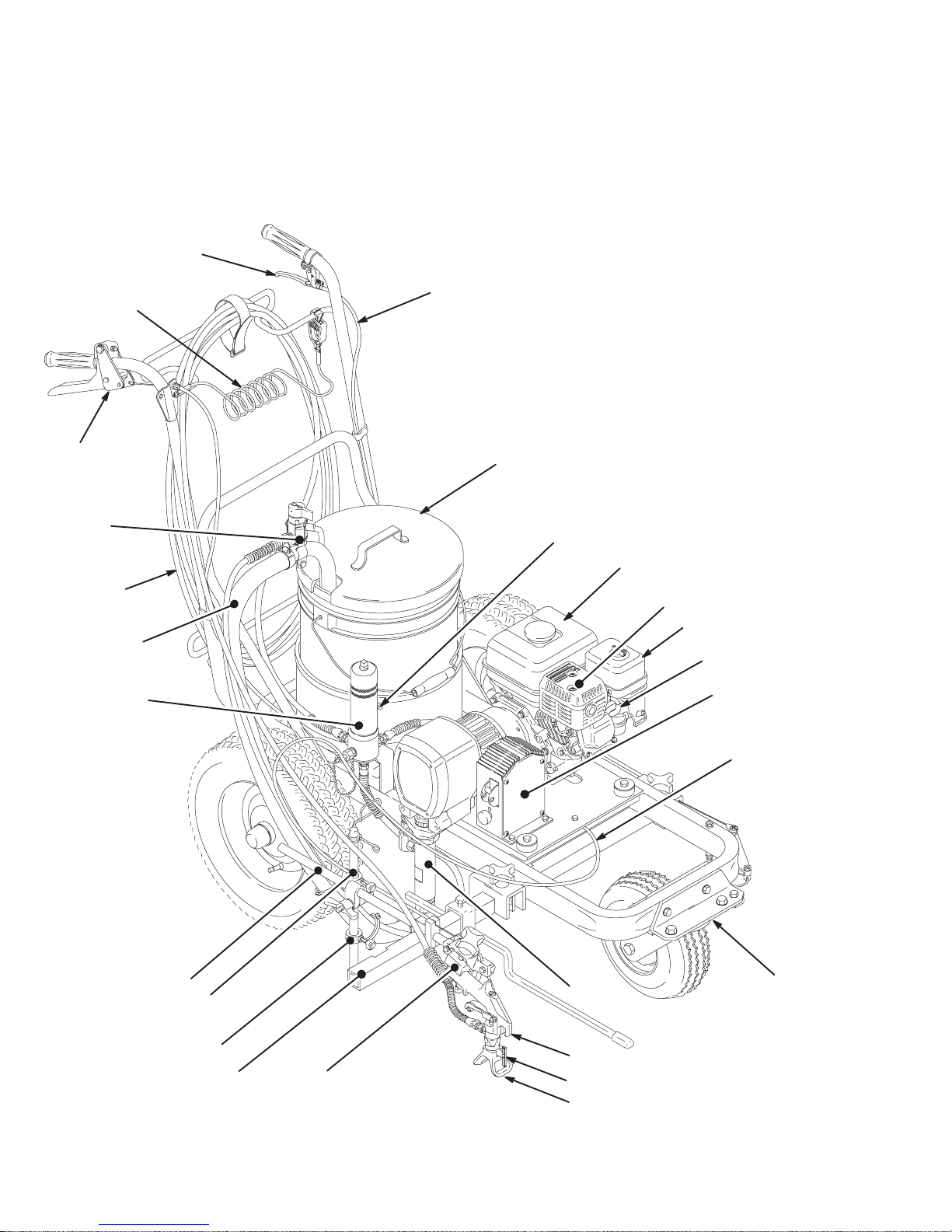
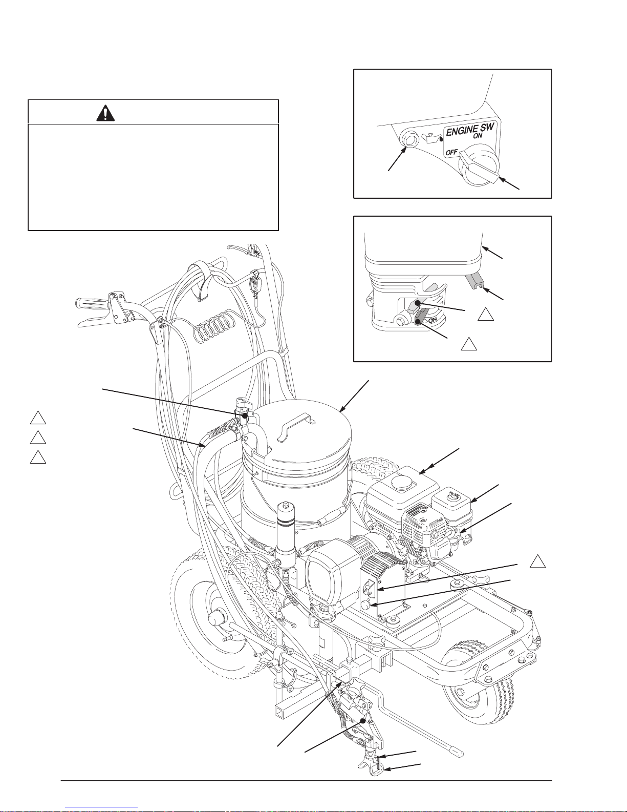
Part Identification
Key
A Caster lever
B Dual gun selector
C Main hose
D Suction hose
E Fluid filter
F Pressure drain valve
G Arm
H Post
A
Z
B
Y
X
F
J Carriage bar
K Gun holder
L Rac IV tip guard
M Switch T ip
N Flex gun
O Displacement pump
P Caster
Q Dual gun selector cable
R Pressure control
S Spark plug cable
T Air Cleaner
U Muffler
V Fuel T ank
W Hook eyelet (use to strap
pail or pail cover to cart)
X Pail cover
Y Caster Cable
Z Grounding cable and
clamp
AA Collar
W
V
C
U
T
D
S
R
E
Q
G
H
O
P
AA
J
K
2 308-082
N
M
L
0001F
Page 3

Table of Contents
Warnings 4. . . . . . . . . . . . . . . . . . . . . . . . . . . . . . . . . . . . . .
Setup 7. . . . . . . . . . . . . . . . . . . . . . . . . . . . . . . . . . . . . . . . .
Fueling 10. . . . . . . . . . . . . . . . . . . . . . . . . . . . . . . . . . . . . . .
Second Gun and Hose Installation 11. . . . . . . . . . . . . . .
Flushing 12. . . . . . . . . . . . . . . . . . . . . . . . . . . . . . . . . . . . . .
Startup 13. . . . . . . . . . . . . . . . . . . . . . . . . . . . . . . . . . . . . . .
Spray Tip and Tip Guard 15. . . . . . . . . . . . . . . . . . . . . . .
Gasket Selection 15. . . . . . . . . . . . . . . . . . . . . . .
Installation 15. . . . . . . . . . . . . . . . . . . . . . . . . . . .
Operation 15. . . . . . . . . . . . . . . . . . . . . . . . . . . . .
Clearing a Clogged Tip 15. . . . . . . . . . . . . . . . . .
Maintenance 15. . . . . . . . . . . . . . . . . . . . . . . . . . .
Spray Tip Selection 16. . . . . . . . . . . . . . . . . . . . . . . . . . . .
Spray Tip Application Recommendations 16. .
Spray Techniques 16. . . . . . . . . . . . . . . . . . . . . . . . . . . . .
Line Width Adjustment 16. . . . . . . . . . . . . . . . . .
Positioning the Gun Arm Assembly 17. . . . . . . . . . . . . .
Vertical position of the first or second gun 17.
Horizontal position of the first gun 17. . . . . . . .
Horizontal position of the second gun 17. . . . .
Mount guns on the engine side of the cart 18.
Setup for spraying arcs 18. . . . . . . . . . . . . . . . .
Adjust Simultaneous Gun Triggering 18. . . . . . . . . . . . .
Gun Arm Positions 19. . . . . . . . . . . . . . . . . . . . . . . . . . . .
Caster Lever & Cable Operation 20. . . . . . . . . . . . . . . . .
Operation 20. . . . . . . . . . . . . . . . . . . . . . . . . . . . .
Maintenance 20. . . . . . . . . . . . . . . . . . . . . . . . . . .
Caster Tire Replacement 20. . . . . . . . . . . . . . . .
Caster Cable Tension Adjustment 20. . . . . . . .
Caster Alignment 20. . . . . . . . . . . . . . . . . . . . . . .
How to Mount the Gun 20. . . . . . . . . . . . . . . . . . . . . . . . .
Gun Cable & Dual Gun Selector Operation 21. . . . . . . .
How the Dual Gun Selector Works 21. . . . . . . .
How to Release the Selector Cable 21. . . . . . .
Adjust the Trigger Cable Tension 22. . . . . . . . .
Maintenance 23. . . . . . . . . . . . . . . . . . . . . . . . . . . . . . . . . .
Troubleshooting 24. . . . . . . . . . . . . . . . . . . . . . . . . . . . . . .
Repair or Replacement
Pressure Control 26. . . . . . . . . . . . . . . . . . . . . . .
Pressure Control Adjustment 27. . . . . . . . . . . .
Bearing Housing and Connecting Rod 28. . . . .
Drive Housing 29. . . . . . . . . . . . . . . . . . . . . . . . .
Pinion Housing 30. . . . . . . . . . . . . . . . . . . . . . . . .
Clutch 32. . . . . . . . . . . . . . . . . . . . . . . . . . . . . . . .
Engine 33. . . . . . . . . . . . . . . . . . . . . . . . . . . . . . . .
Field & Wiring Harness 34. . . . . . . . . . . . . . . . . .
Clamp 35. . . . . . . . . . . . . . . . . . . . . . . . . . . . . . . .
Clutch Housing Removal 35. . . . . . . . . . . . . . . .
Reassembly 36. . . . . . . . . . . . . . . . . . . . . . . . . . .
Parts
Pressure Control Parts 39. . . . . . . . . . . . . . . . . .
Cart Parts 40. . . . . . . . . . . . . . . . . . . . . . . . . . . . .
Mechanical Parts 42. . . . . . . . . . . . . . . . . . . . . . .
Gun Mounting Parts 44. . . . . . . . . . . . . . . . . . . .
Pinion Parts 45. . . . . . . . . . . . . . . . . . . . . . . . . . .
Technical Data 46. . . . . . . . . . . . . . . . . . . . . . . . . . . . . . . .
Accessories 46. . . . . . . . . . . . . . . . . . . . . . . . . . . . . . . . . .
Warranty 48. . . . . . . . . . . . . . . . . . . . . . . . . . . . . . . . . . . . .
Manual Change Summary
This manual has been updated to add items 194 – 196 and change item 2 to 240–484 from 238–361.
3308-082
Page 4
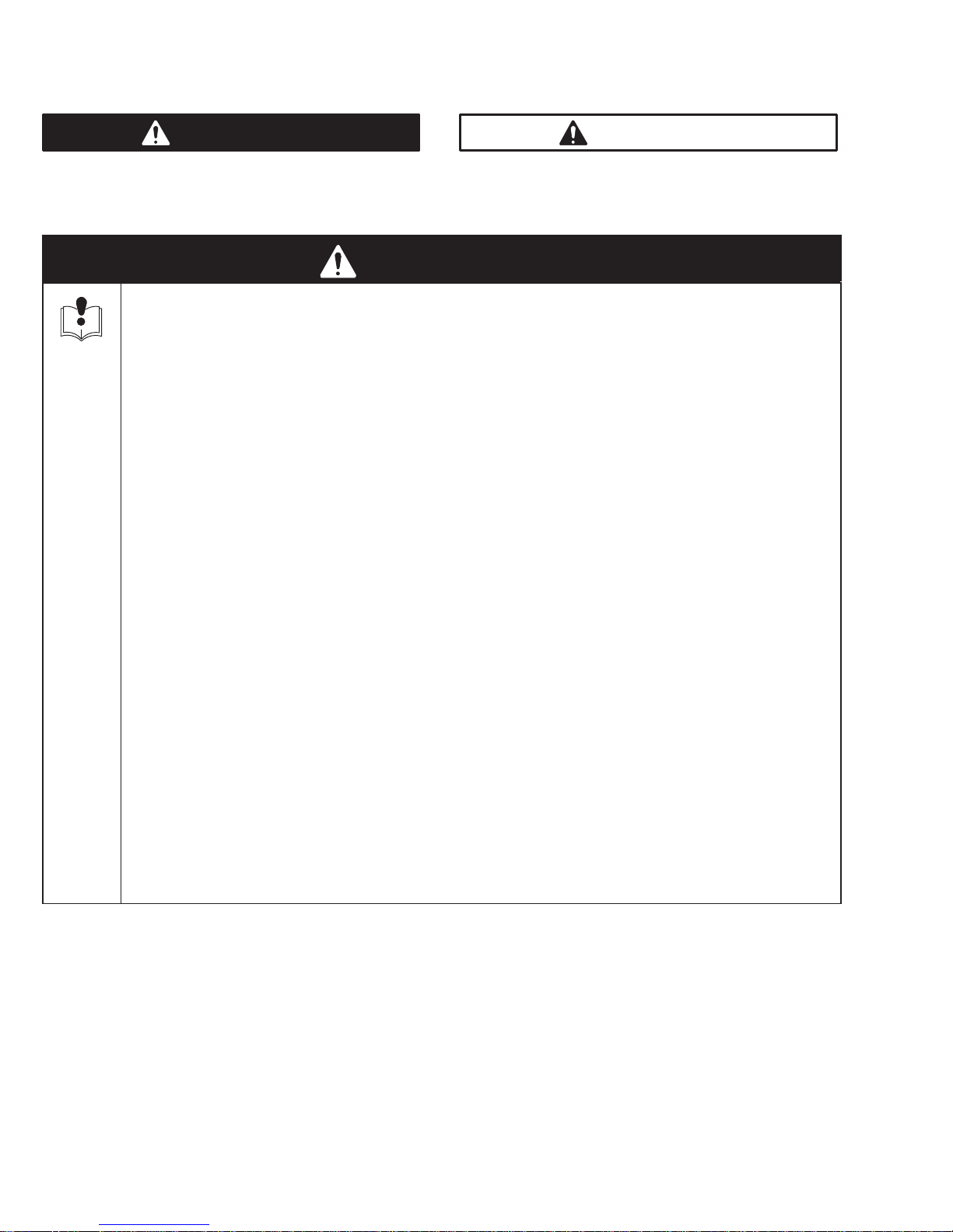
Symbols
Warning Symbol
WARNING
This symbol alerts you to the possibility of serious
injury or death if you do not follow the instructions.
WARNING
EQUIPMENT MISUSE HAZARD
Equipment misuse can cause the equipment to rupture or malfunction and result in serious injury.
INSTRUCTIONS
D This equipment is for professional use only.
D Read all instruction manuals, tags, and labels before operating the equipment.
D Use the equipment only for its intended purpose. If you are not sure, call your distributor.
D Do not alter or modify this equipment.
D Check equipment daily. Repair or replace worn or damaged parts immediately.
Caution Symbol
CAUTION
This symbol alerts you to the possibility of damage to
equipment if you do not follow the instructions.
D Do not exceed the maximum working pressure of the lowest rated system component. Refer to the
Technical Data on page 46 for the maximum working pressure of this equipment.
D Use fluids and solvents which are compatible with the equipment wetted parts. Refer to the Tech-
nical Data section of all equipment manuals. Read the fluid and solvent manufacturer’s warnings.
D Do not use hoses to pull equipment.
D Route hoses away from traffic areas, sharp edges, moving parts, and hot surfaces. Do not expose
Graco hoses to temperatures above 82_C (180_F) or below –40_C (–40_F).
D Do not lift pressurized equipment.
D Comply with all applicable local, state, and national fire, electrical, and safety regulations.
D Wear hearing protection when operating this equipment.
D Do not use 1,1,1–trichloroethane, methylene chloride, other halogenated hydrocarbon solvents or
fluids containing such solvents in pressurized aluminum equipment. Such use could result in a
chemical reaction, with the possibility of explosion.
4 308-082
Page 5
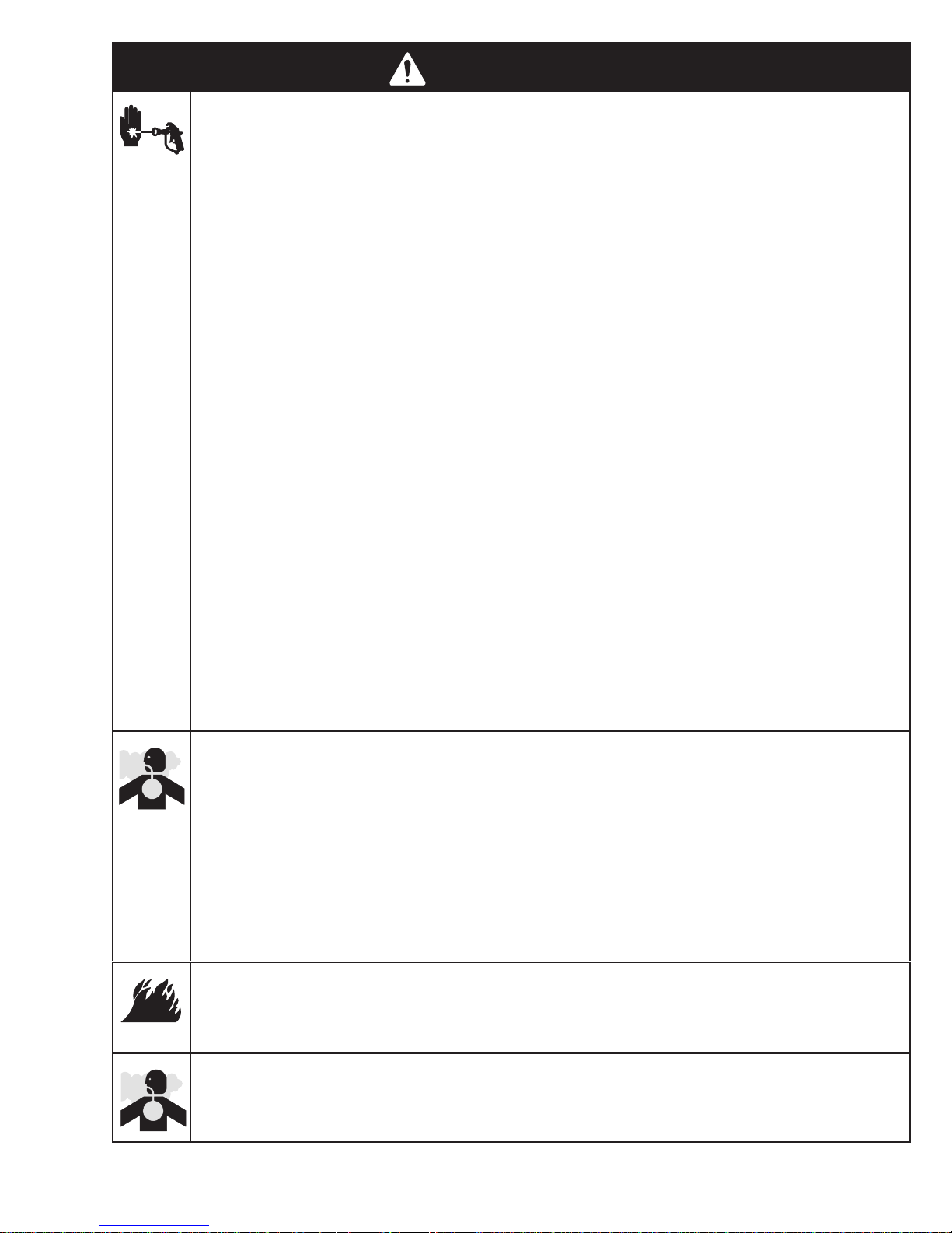
WARNING
INJECTION HAZARD
Spray from the gun, leaks or ruptured components can inject fluid into your body and cause extremely
serious injury, including the need for amputation. Fluid splashed in the eyes or on the skin can also
cause serious injury.
Fluid injected into the skin may look like just a cut, but it is a serious injury. Get immediate medi-
cal attention.
Do not point the gun at anyone or at any part of the body.
Do not put your hand or fingers over the spray tip.
Do not stop or deflect leaks with your hand, body, glove or rag.
Do not “blow back” fluid; this is not an air spray system.
Always have the tip guard and the trigger guard on the gun when spraying.
Check the gun diffuser operation weekly. Refer to the gun manual.
Be sure the gun trigger safety operates before spraying.
Lock the gun trigger safety when you stop spraying.
Follow the Pressure Relief Procedure on page 7 if the spray tip clogs and before cleaning,
checking or servicing the equipment.
Tighten all fluid connections before operating the equipment.
Check the hoses, tubes, and couplings daily. Replace worn or damaged parts immediately. Do not
repair high pressure couplings; you must replace the entire hose.
Fluid hoses must have spring guards on both ends, to help protect them from rupture caused by
kinks or bends near the couplings.
TOXIC FLUID HAZARD
Hazardous fluid or toxic fumes can cause serious injury or death if splashed in the eyes or on the skin,
inhaled, or swallowed.
Know the specific hazards of the fluid you are using.
Store hazardous fluid in an approved container. Dispose of hazardous fluid according to all local,
state and national guidelines.
Always wear protective eyewear, gloves, clothing and respirator as recommended by the fluid and
solvent manufacturer.
FUEL HAZARD
The fuel used in this unit is combustible and when spilled on a hot surface can ignite and cause a fire.
Do not fill the fuel tank while the engine is running or hot.
EXHAUST HAZARD
The exhaust contains poisonous carbon dioxide which is colorless and odorless.
Do not operate this equipment in a closed building.
5308-082
Page 6

WARNING
FIRE AND EXPLOSION HAZARD
Improper grounding, poor ventilation, open flames or sparks can cause a hazardous condition and
result in a fire or explosion and serious injury.
If there is any static sparking or you feel an electric shock while using this equipment, stop spray-
ing immediately. Do not use the equipment until you identify and correct the problem.
Provide fresh air ventilation to avoid the buildup of flammable fumes from solvents or the fluid
being sprayed.
Keep the spray area free of debris, including solvent, rags, and gasoline.
Disconnect all electrical equipment in the spray area.
Extinguish all open flames or pilot lights in the spray area.
Do not smoke in the spray area.
Do not turn on or off any light switch in the spray area while operating or if fumes are present.
Do not operate a gasoline engine in the spray area.
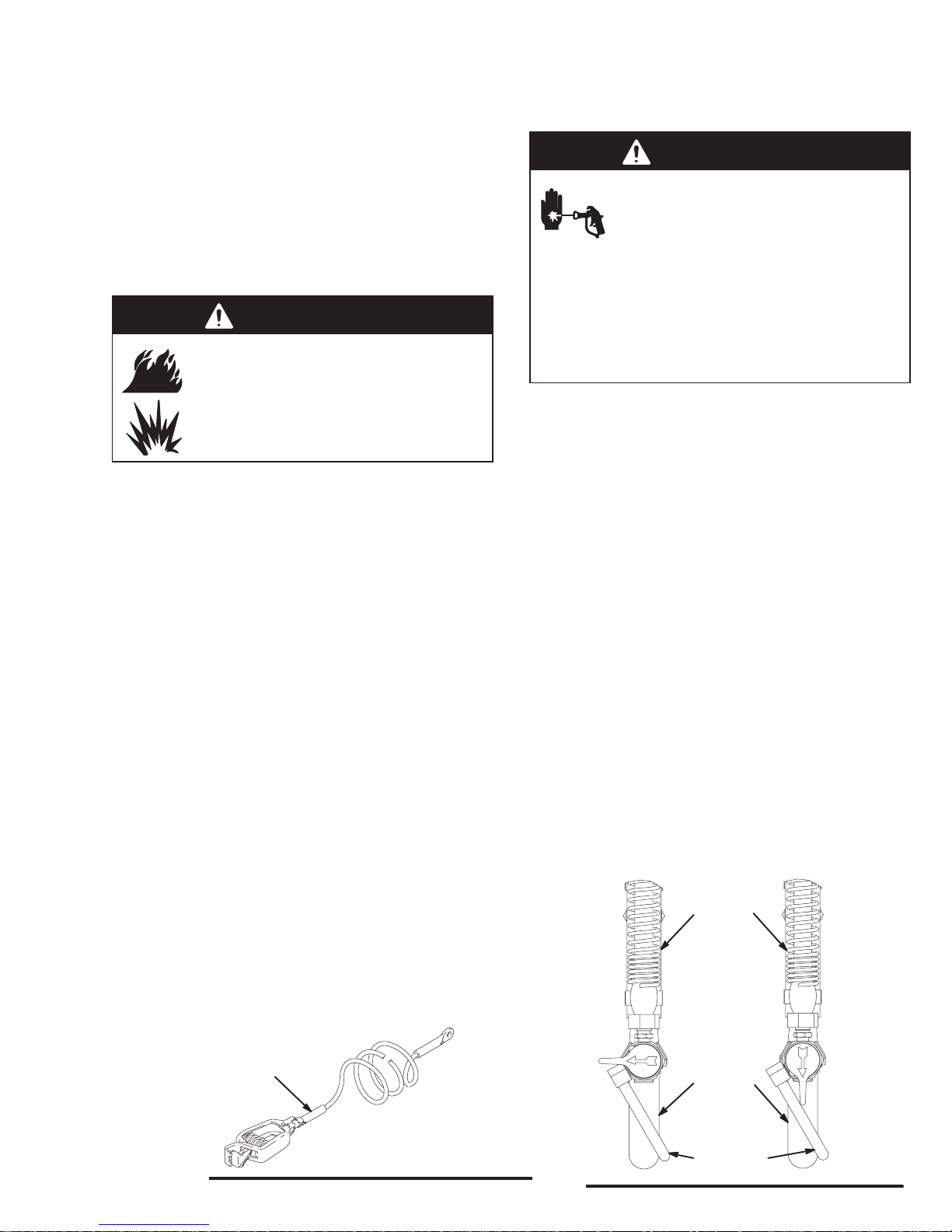
Ground the sprayer to a true earth ground with the ground wire and clamp (supplied).
Use only electrically conductive hoses.
MOVING PARTS HAZARD
Moving parts can pinch or amputate your fingers.
Keep clear of all moving parts when starting or operating the sprayer.
Before servicing the equipment, follow the Pressure Relief Procedure on page 7 to prevent the
equipment from starting unexpectedly.
FIRE AND
EXPLOSION HAZARD
Spray painting, flushing or cleaning equipment with flammable
liquids in confined areas can result in fire or explosion.
Use outdoors or in extremely well ventilated areas. Ground
equipment, hoses, containers and objects being sprayed.
Avoid all ignition sources such as static electricity from plastic
drop cloths, open flames such as pilot lights, hot objects such as
cigarettes, arcs from connecting or disconnecting power cords
or turning light switches on and off.
Failure to follow this warning can result in death or serious injury.
READ AND UNDERST AND ALL LABELS AND INSTRUCTION MANUALS BEFORE USE
SKIN INJECTION
HAZARD
Liquids can be injected into the body by high pressure airless
spray or leaks – especially hose leaks.
Keep body clear of the nozzle. Never stop leaks with any part of the
body . Drain all pressure before removing parts.Avoid accidental
triggering of gun by always setting safety latch when not spraying.
Never spray without a tip guard.
In case of accidental skin injection, seek immediate
“Surgical Treatment”.
Failure to follow this warning can result in amputation or serious
injury .
6 308-082
Page 7
Setup
General Information
NOTE: Reference numbers and letters in parentheses
in the text refer to the callouts in the figures and the
parts drawing.
NOTE: Always use Genuine Graco Parts and Accessories, available from your Graco distributor.
Grounding
WARNING
FIRE AND EXPLOSION HAZARD
Before operating the pump, ground the
system as explained below. Also read
the section FIRE OR EXPLOSION HAZ-
ARD on page 6.
1.
Sprayer:
contacts the ground while the unit is moving. See
page 42. For stationary spraying, connect a
ground wire and clamp (159) to a true earth
ground.
2.
Fluid hoses:
maximum of 500 ft. (150 m) combined hose
length to ensure grounding continuity.
3.
Spray gun:
a properly grounded fluid hose and sprayer.
4.
Object being sprayed:
5.
Fluid supply container:
6.
Solvent pails used when flushing:
code. Use only metal pails, which are conductive,
placed on a grounded surface. Do not place the
pail on a nonconductive surface, such as paper or
cardboard, which interrupts the grounding continuity.
7.
To maintain grounding continuity when flushing or
relieving pressure
gun firmly to the side of a grounded
then trigger the gun.
make sure the grounding chain (106)
use only grounded hoses with a
obtain grounding through connection to
according to local code.
follow your local code.
follow your local
, hold a metal part of the spray
metal
pail,
Pressure Relief Procedure
WARNING
INJECTION HAZARD
Fluid under high pressure can be injected through the skin and cause seri-
ous injury. To reduce the risk of an injury
from injection, splashing fluid, or moving parts, follow the Pressure Relief Procedure whenever you:
are instructed to relieve the pressure,
stop spraying,
check or service any of the system equipment,
or install or clean the spray tips.
1. Engage the spray gun safety latch.
2. Turn the ON/OFF switch to OFF.
3. Flip the pressure control switch to OFF.
4. Disengage the gun safety latch. Hold a metal part
of the gun firmly to the side of a grounded metal
pail, and trigger the gun to relieve pressure.
5. Engage the gun safety latch.
6. Hold the pressure relief tube firmly to the side of a
grounded metal pail, and open the pressure relief
valve. Leave the valve open until you are ready to
spray again.
7. Disconnect the spark plug cable to prevent the
system from starting unexpectedly.
If you suspect that the spray tip or hose is completely
clogged, or that pressure has not been fully relieved
after following the steps above, very slowly
tip guard retaining nut or hose end coupling and relieve
pressure gradually, then loosen completely. Now clear
the tip or hose.
Valve shown in
CLOSED position.
Pressure
Valve shown
in OPEN position.
Hose
loosen the
159
Fig. 1
Fig. 2
Suction
Tube
Pressure
Relief Tube
06877
7308-082
Page 8
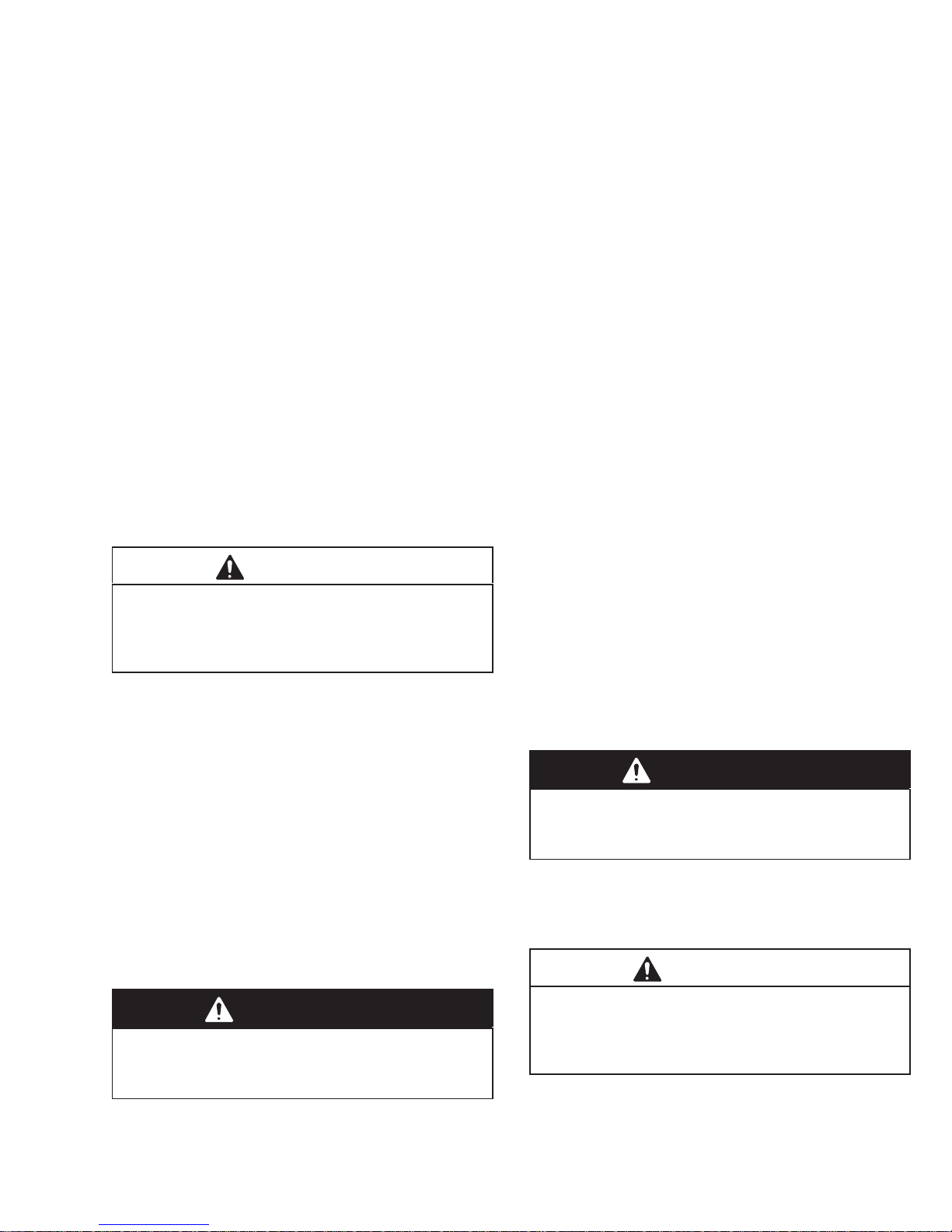
Setup
1. Read and follow the warnings on pages 4 and 6
before installing or operating this sprayer.
2. Unpack the LineLazer Carefully raise the handle (19)
to a vertical position. Four screws (39) and locknuts
(40) are packed in a bag. Install the two rear screws
(39A) and finger tighten the nuts (40A). Install one
screw (39B) and nut (40B) on each side of the handle. Firmly tighten all four nuts. See Fig. 3.
CAUTION
When raising the cart handle (19), be sure no cables
are caught on the frame or become kinked.
3. To install a second gun and hose, see page 11.
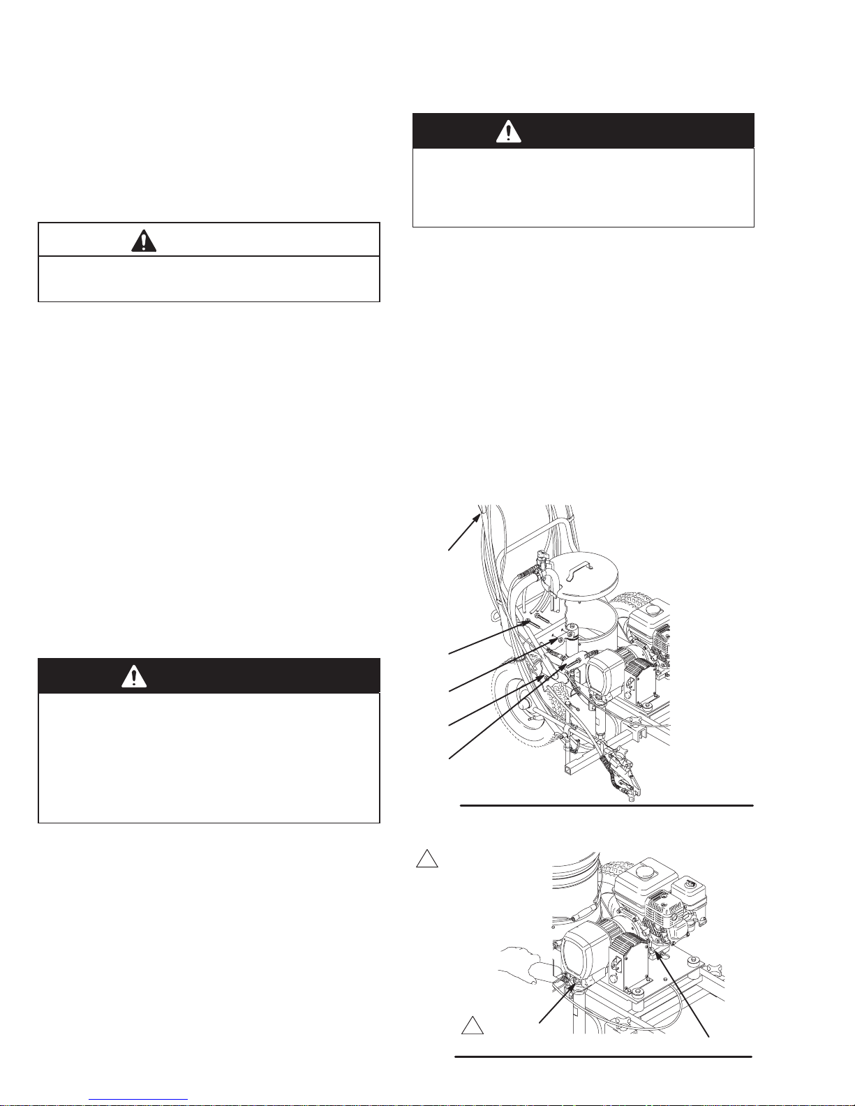
4. Fill the packing nut/wet–cup (216) 1/3 full with
Graco Throat Seal Liquid (TSL), supplied, and
keep it filled, to help extend the pump life. See
Fig. 4.
5. Check the engine oil level. Refer to the Honda
engine manual, supplied. This is a summary of the
information: Remove one of the oil fill plugs (A);
the oil should be almost overflowing. See Fig. 4.
Add oil as necessary. Also read the Maintenance
section on page 23.
7. Provide adequate ventilation when spraying indoors.
WARNING
If the LineLazer is used indoors, you must vent the
exhaust to the outdoors or provide adequate ventilation as specified by you local code. This is to
reduce the risk of carbon monoxide poisoning.
8. Fill the gas tank. See Fueling on page 10.
9. Flush the pump to remove the lightweight oil which
was left in the pump to protect it from rust. Follow the
Flushing on page 12.
10. Prepare the paint according to the manufacturer ’s
recommendations. Remove any skin that may have
formed. Stir the paint to mix pigments.
Strain the paint through a fine nylon mesh bag (available at most paint dealers) to remove particles that
could clog the filter or spray tip. This is an important
step toward trouble–free spraying.
Recommended engine oil: Use a high–quality , detergent oil, SAE 10W–40, classified “FOR SERVICE
SE or SF”.
6. Ground the sprayer. Proper grounding is essential to
maintaining an electrically safe system. Also read
and follow FIRE OR EXPLOSION HAZARD on page
6.
WARNING
Ground the sprayer whenever it is used indoors,
either as a moving line striper or as a stationary
sprayer. Floors in most factories are coated, which
causes them to be poor electrical conductors. This
increases the risk of hazardous static electric
discharge, which can result in serious injury, fire, or
explosion and property damage.
Whenever you flush: connect the ground clamp
(159) to a true earth ground.
Using as an outdoor striper: Be sure the static
chain attached to the bottom of the cart drags on the
ground to help dissipate static electricity . Ground the
sprayer to a true earth ground if specified by your
local electrical code.
Indoor spraying: Ground the sprayer whenever the
sprayer is used indoors. The ground wire supplied
with the sprayer is not long enough to allow much
operator movement. Therefore, the operator must
provide a longer ground wire or provide some other
method of effective electrical grounding as specified
by your local electrical code.
8 308-082
19
39A
40A
40B
39B
Fig. 3
Keep filled with TSL
Fig. 4
0007D
216
A
0008
Page 9

Setup
11. Observe the following cautions to avoid pressure
control damage.
CAUTION
To avoid damaging the pressure control, follow these
precautions.
Allow the main hose to act as a pulsation damp-
ener: Always use nylon spray hose at least 50 ft.
(15 m) long for the main gun; Never use a wire
braid hose; it is too rigid.
Never install a ball valve or shutoff device be-
tween the filter and the 50 ft. (15 m) hose.
Do not allow water or water-base material to
freeze in the pressure control.
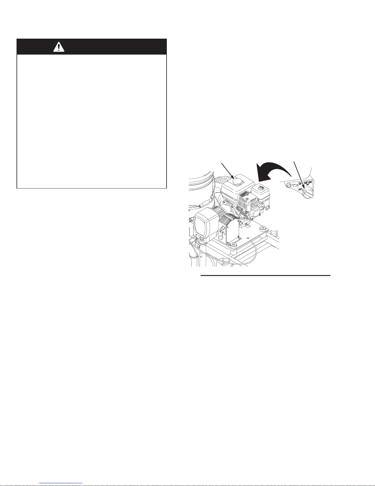
CAUTION
Close the black fuel shutoff lever whenever you are
transporting the sprayer to prevent fuel from flooding
the engine.
12. To use the wheel brake, lift the brake handle (A–
bottom rear of cart) to engage the brake. Lower
the handle to disengage the break. See Fig. 5. For
positive break engagement, be sure there is
proper tire pressure and that tire wear is not
excessive.
13. For how to operate and adjust the various features
of the LineLazer see pages 11 – 22.
14. Start the sprayer. See page 13.
A
Keep the sprayer upright and level when operating it
and transporting it. This prevents crankcase oil from
leaking into the combustion chamber, which makes
startup very difficult.
Fig. 5
03586
9308-082
Page 10
Fueling
WARNING
Gasoline is extremely flammable and explosive
under certain conditions. To reduce the risk or a fire
or explosion:
1. Always shut off the engine before refueling.
NOTE: The HONDA engine warranty does not cover
damage resulting from the use of gasolines containing alcohol. See the HONDA engine manual for more information.
3. General. Do not use oil and gasoline mixtures or contaminated gasoline. Avoid getting dirt, dust or water
in the fuel tank.
2. Refuel in a well-ventilated area.
3. Do not smoke or allow flames or sparks in the
area where the engine is refueled or where
gasoline is stored.
4. Do not overfill the tank. Make sure the filler cap
is securely closed after refueling.
5. Fuel vapor or spilled fuel can ignite. If any fuel
is spilled during refueling, make sure the area
is dry before starting the engine.
1. Fuel specifications. Use automotive gasoline with
a pump octane number of 86 or higher. If the
engine knocks or pings, use a higher octane fuel.
Unleaded fuel minimizes combustion chamber
deposits.
2. Gasolines containing alcohol (gasohol). Do not use
gasohol which contains methanol, if the gasohol
does not contain cosolvents and corrosion inhibitors for methanol. Even if it does contain such
additives, do not use the gasohol if it contains
more than 5% methanol.
4. Tank capacity: 0.66 gallons (2.5 liter). Leave 1/2 in.
(13 mm) at the top of the tank for gas expansion.
5. Shut off the engine switch (A) before refueling.
6. After refueling, tighten the fuel tank cap (B) firmly.
B
Fig. 6
A
0009
10 308-082
Page 11
Second Gun and Hose Installation
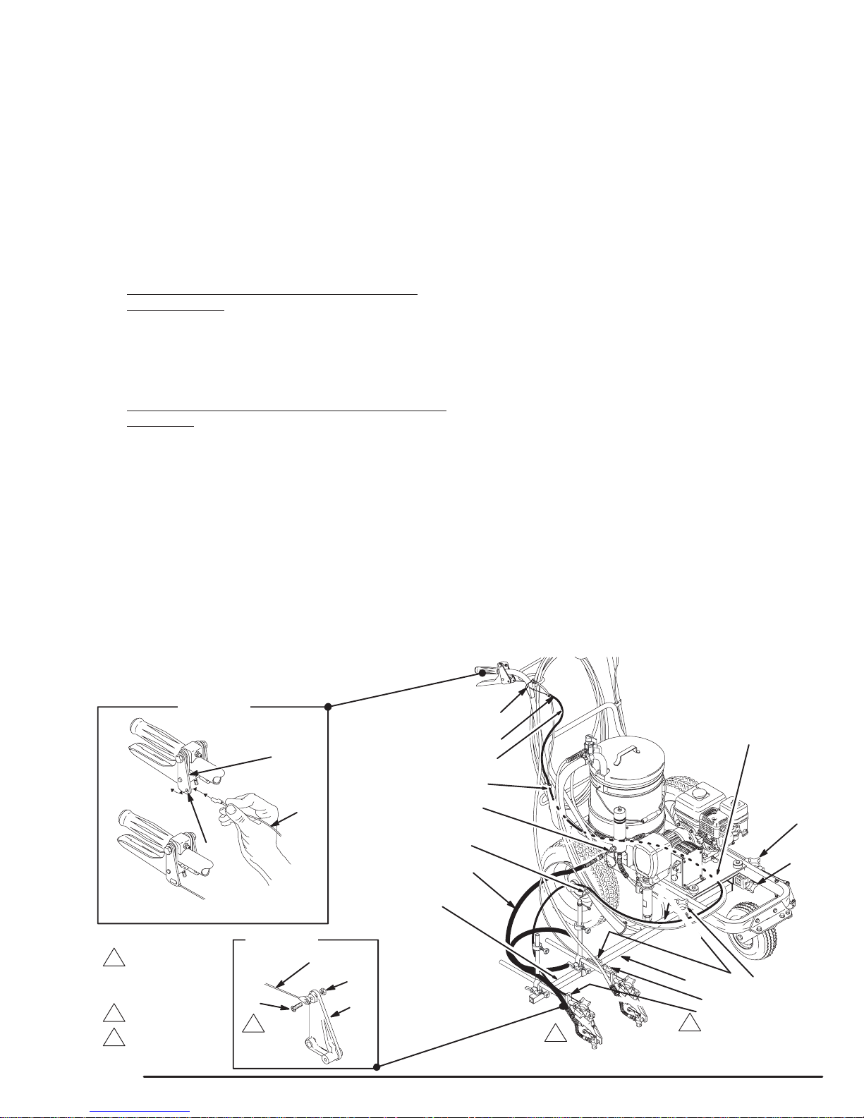
NOTE: Fig. 7 represents the installation at Step 3.
NOTE: To switch the gun assemblies to the engine side
of the cart, refer to the instructions on page 17 before installing the second gun kit.
1. Disengage the trigger cable from the block (48) of
the unit’s existing gun. See page 21. Engage the
gun’s trigger safety latch.
2. Loosen the carriage clamps (B, C). Slide the
carriage bar (4) off the cart.
3. For mounting the second gun bar on the pump
side of the cart: Slide a clamp (405A) onto the
carriage bar (4). Slide the carriage bar through the
pump-side carriage clamp (B) and into the center
of the cart. Now slide another clamp (405B) onto
the carriage bar. See Fig. 7.
For mounting the second gun bar on the engine side
of the cart: Follow Step 3, except slide the carriage
bar through the engine-side carriage clamp (C) and
the into the center of the cart. The knobs of the
clamps (405A, 405B) must face back toward the
handle bars.
4. Slide the carriage bar (4) through to the opposite carriage clamp. Tighten the carriage clamps (B,C).
5. Slide the second gun bar (404) far enough into the
carriage bar that the clamp (405B) engages the bar.
Position the clamps (405A, 405B) over the notches
(A) in the carriage bar (4) and tighten the clamps.
6. Disconnect the trigger cable from the second gun at
the screw (34). See Fig. 7 DETAIL B.
7. Unscrew the filter’s second outlet cap (14). Screw
the short hose (403) onto the filter nipple.
8. Remove the guide clamp screw (27).
9. Snap the cable bushing (E) into the guide plate (D).
Route the trigger cable (402) parallel with the main
gun cable, separating the guide clamp (104) to feed
the cable through it. Install and tighten the clamp
screw (27). Route the cable through the cable guide
(7) and to the second gun.
10. Slide the hooked end of the cable (402) through the
hole (F) in the lever plate (122). Rotate and slide the
hook back until it engages the plate. See DET AIL A.
11. Reconnect the trigger cable to the second gun at
screw (34). Torque the screw to 15 in–lb (1.7 N.m),
back it off 1/16 to 1/8 turn and then tighten the jam
nut (99) while holding the screw (34). Be sure the
plate (94) moves freely.
12. Install the clip (401) to hold the cable onto the frame.
13. Connect both trigger cables to the blocks (48). Then
adjust the cable tension. See pages 20 and 22.
14. Do not install the spray tip until the system is primed.
15. Adjust simultaneous gun triggering. See page 18.
NOTE: For stable gun operation, the second
gun bar (404) has a maximum recommended
extension from the carriage bar of about
11-1/4” (286 mm).
DETAIL A
HOW TO INSTALL CABLE
122
F
CORRECTL Y INSTALLED CABLE
T orque to 15 in–lb
(1.7 N.m)
and then back up
1/16 to 1/8 turn
First gun
Second gun
DETAIL B
34
Fig. 7
402
402
99
94
404
403
402
401
14
7
D
E
27,104
C
405B
4
A
B
405A
48
02490C
11308-082
Page 12
Flushing
WARNING
To reduce the risk of serious injury whenever you
are instructed to relieve pressure, always follow the
Pressure Relief Procedure on page 7.
Be sure the pump is properly grounded.
CAUTION
Never leave water in the sprayer if the is any chance
it could freeze. Push the water out with compatible
solvent. Water frozen in the pressure control tube
prevents the sprayer from being started, and causes
serious damage to the pressure control.
When to Flush
1. Flush a new sprayer to remove the protective oil.
Before using water–base paint, use compatible sol-
vent, then soapy water, and then clean water.
Before using oil–base paint, use compatible solvent.
WARNING
To reduce the risk of static sparking and splashing
when flushing, always remove the spray tip from
the gun, and hold a metal part of the gun firmly to
the side of, and aimed into, a grounded metal pail.
6. Follow Startup on page 13. Keep the gun triggered
until clean water or solvent comes from the nozzle.
See Fig. 9. Release the trigger and engage the gun
safety latch.
NOTE: If you have two guns, release the trigger safety
latch on the second gun and trigger that gun until clean
water or solvent comes from the nozzle. To ensure that
the hoses are well-flushed, flush the first gun and then the
second gun at least one more time.
7. Check all fluid connections for leaks. Relieve pressure before tightening any connections. Start the
sprayer. Recheck the connections for leaks.
8. Remove the suction tube from the solvent pail. Disengage the gun safety latch. T rigger the gun to force
water or solvent from the hose. Do not let the pump
run dry for more than 30 seconds to avoid damaging
the pump packings! Relieve pressure.
2. Changing colors. Use a compatible solvent.
3. Changing from water–base to oil–base paint. Use
warm, soapy water, and then a compatible solvent.
4. Changing from oil–base to water–base paint. Use a
compatible solvent, then warm, soapy water, and
then clean water.
5. Storage. After the compatible solvent flush, relieve
pressure, but do not drain the compatible solvent.
6. Startup after storage.
Before using water–base paint, flush out the compatible solvent with soapy water, and then with clean
water.
When using oil–based paint, flush out the compatible
solvent with the paint to be sprayed.
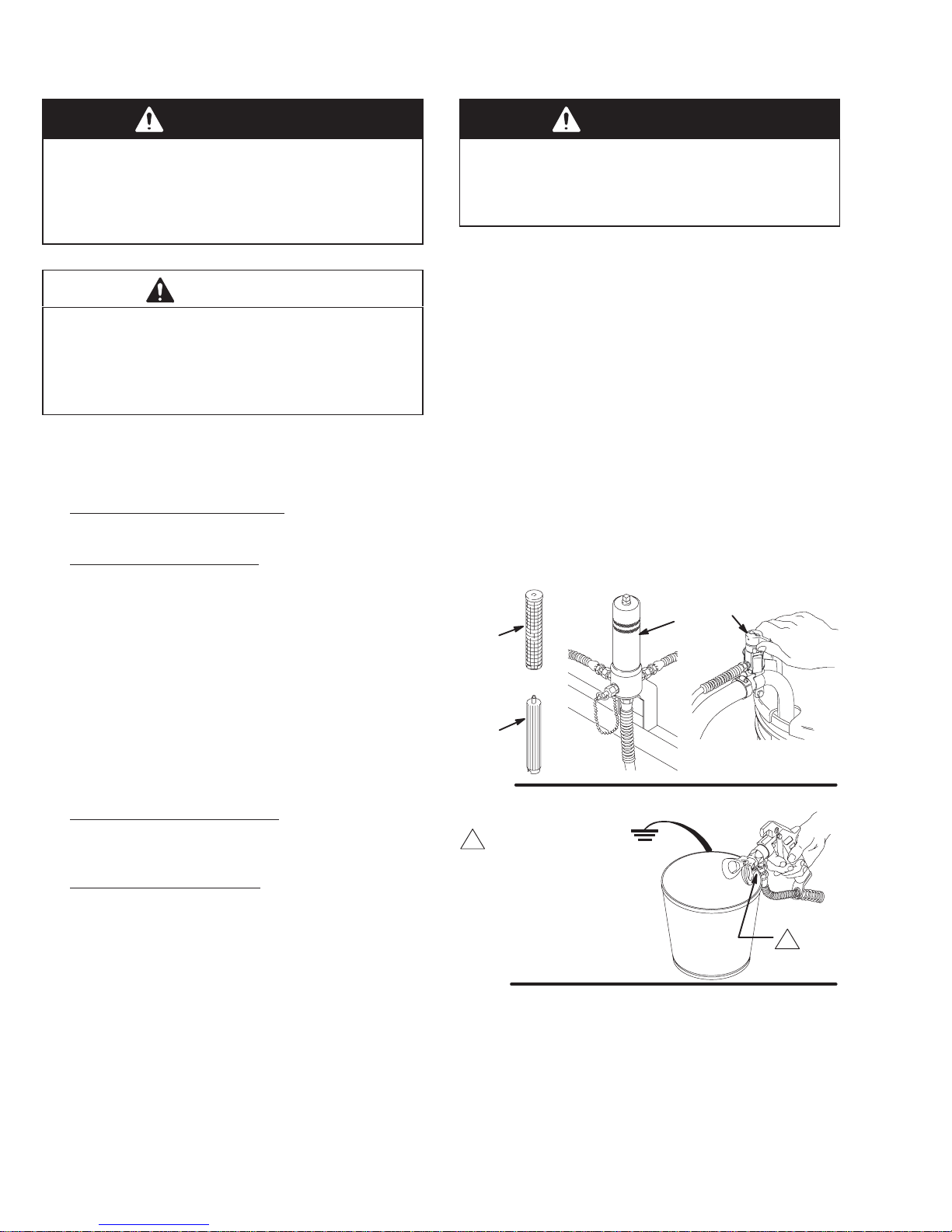
How to Flush
1. Relieve pressure.
2. Remove the filter bowl (A) and screen (B); see manual 307–273. Install the bowl and support (C), without
the screen, to flush it. Clean the screen separately.
See Fig. 8.
3. Close the pressure drain valve (13).
4. Put the suction tube in a grounded pail of water or
solvent.
13
A
B
C
Fig. 8
Maintain firm metal-
to-metal contact
when flushing to
reduce the chance
of static sparking
and splashing.
Fig. 9
9. If you have been spraying paint, remove the strainer,
suction tube and suction hose and clean them separately to be sure all paint sediment is removed. Dried
paint in the suction tube assembly can build up and
cause performance problems later on.
10. Install the clean filter screen. Install the filter bowl and
hand tighten.
0013
0014
5. Remove the gun(s) from the holder. Remove the
spray tip(s) to prevent splashing.
12 308-082
11. See Storage or Changing Colors, above. Relieve
pressure.
Page 13
Startup
Before You Start the Linestriper
1. See Flushing, page 12, to determine if the Line Lazer
should be flushed.
2. Be sure the gas tank is full.
3. Check the engine oil level.
NOTE: The engine stops automatically, or will not start,
if it is low on oil. If you try to start it again without adding
more oil, a red light (A) near the engine on/off switch
glows as you pull the starter rope.
4. Be sure the spark plug cable (J) is firmly pushed onto
the spark plug.
Startup See Fig. 10
1. When starting a sprayer that IS NOT PRIMED, remove the spray tip.
2. Place the suction tube (S) into the paint, water or solvent container, depending on whether you are flushing or are ready to spray.
3. Open the black fuel shutoff lever (E) by pushing it in
the direction of the arrow.
CAUTION
Never start the engine unless fluid pressure is relieved and the pressure control switch is turned OFF.
Attempting to start the engine when it is pressurized
could damage the electrical system.
4. Turn OFF the pressure control switch (K).
5. To start the engine:
g. Open the choke as soon as the engine starts,
except in cold weather. In cold weather, leave
the choke closed for 10 to 30 seconds before
opening it to keep the engine running.
6. Release the trigger cable and engage the gun trigger
safety latch. See page 21.
7. Remove the gun from the holder by unscrewing the
gun holder knob and lifting out the gun.
8. To start the pump:
NOTE: Lower the throttle setting for easier priming.
a. Open the pressure drain valve (R).
b. Turn ON the pressure control switch (K).
c. Turn the pressure control knob (L) about 1/4
turn from minimum pressure. Run the pump
until fluid is flowing smoothly from the pressure
drain valve, indicating the pump is fully primed.
d. Close the pressure drain valve (R).
e. Disengage the gun safety latch. Hold a metal
part of the gun firmly against a grounded metal
pail, squeeze the trigger until fluid flows from
the gun.
f. Release the trigger. Engage the safety latch.
NOTE: If you are using two guns, follow Step e and f,
above, for the second gun.
9. If you have not primed the sprayer with paint yet,
move the suction tube (S) to the paint container. Release the trigger safety latch. Trigger the gun into the
water/solvent pail just until paint appears. Release
the trigger and engage the trigger safety latch. Repeat for the second gun, if two guns are used.
10. Place the pail cover (F) on the pail.
a. Turn the pressure adjusting knob (L) all the
way counterclockwise to the lowest pressure
setting.
b. Slide the metal throttle lever (C) away from the
fuel tank to the maximum position (fully left).
c. If the engine is cold, close the choke by mov-
ing the gray lever (D).
d. If the engine is warm, close the choke by
moving the gray lever (D) only half way or not
at all.
e. Turn ON the engine switch (B).
WARNING
A rope that recoils too quickly may hit someone
and cause serious bodily injury. The rope could
also jam in the recoil assembly.
f. Hold the frame of the sprayer with one hand
and pull the starter rope (G) rapidly and firmly.
Continue holding the rope as you let it return.
Pull and return the rope until the engine starts.
WARNING
To reduce the risk or serious injury from fluid
injection, never operate the spray gun with the tip
guard removed.
11. Install the tip guard and spray tip (M). See page 15.
12. Mount the gun in the gun holder. See page 20.
13. Engage the trigger cable. See page 21.
CAUTION
Always use the lowest fluid pressure and the lowest
throttle setting needed. Higher settings cause excessive clutch cycling, premature tip wear and premature pump wear.
14. Adjust the engine speed and pump pressure. Trigger
the gun onto a test paper to check the spray pattern
and atomization. Turn the pressure adjusting knob
(L) until you get a good pattern. Then slowly lower the
throttle setting (C) as far as you can without changing
the spray pattern.
13308-082
Page 14
Startup
15. Read Spray Techniques on page 16.
CAUTION
Close the black fuel shutoff lever (E) whenever you
are transporting the sprayer to prevent fuel from
flooding the engine.
Keep the sprayer upright and level when operating it
and when transporting it. This prevents crankcase oil
from leaking into the combustion chamber, which
makes start up very difficult.
A
B
––AT REAR OF ENGINE––
H
R
Shown in
choked position
Shown off
Shown in
off position
KEY
A Engine Oil Light
B Engine On/Off Switch
C Throttle Lever
D Gray Choke Lever
E Black Fuel Shutoff Lever
F Pail Cover
G Starter Rope
H Air Cleaner
J Spark Plug Cable
K Pressure Control On/Off Switch
L Pressure Adjusting Knob
M SwitchT ip
N Rac IV Tip Guard
P Gun Trigger Safety Latch
Q Remote Trigger Cable
R Pressure Drain Valve
S Suction Tube
S
Fig. 10
14 308-082
D
E
F
G
H
J
C
K
L
Q
P
M
N
0001F
0001F
Page 15
Spray Tip and Tip Guard
WARNING
To reduce the risk of serious injury whenever you
are instructed to relieve pressure, always follow the
Pressure Relief Procedure on page 7.
WARNING
Operation
WARNING
Keep clear of the nozzle! High pressure fluid from
leaks or spray can penetrate the skin and cause
extremely serious injury, including the need for
amputation. The spray tip guard provides extra
protection against injection, but does not prevent it!
Never cut off the spray tip guard.
Failure to install or use the RAC IV tip guard assembly correctly may result in an undirected spray
of paint into the eyes or on the skin of the operator.
Be sure you:
Use the appropriate gasket for the solvent used.
Fully insert the tip into the guard.
Fully tighten the guard onto the gun nozzle
using a wrench.
Turn the handle so it is parallel to the gun
nozzle.
When replacing a worn spray tip, always install
a new gasket and seat.
Gasket Selection
WARNING
To reduce the risk of fluid splashback into the eyes
or on the skin, use the appropriate gasket as
specified in the following text.
Use the black rubber gasket (D) ONLY with latex and
oil-based paints, stoddard solvents, mineral spirits, turpentine and water . When using this gasket, the spray tip
can be removed and replaced without using tools.
Use the red or yellow plastic gasket (C) with the same
fluids as above and with most other solvents, including
lacquer thinner, trichloroethylene, MEK, acetone, brush
cleaner, xylol. When using this gasket, loosen the RAC
IV retaining nut to remove the spray tip.
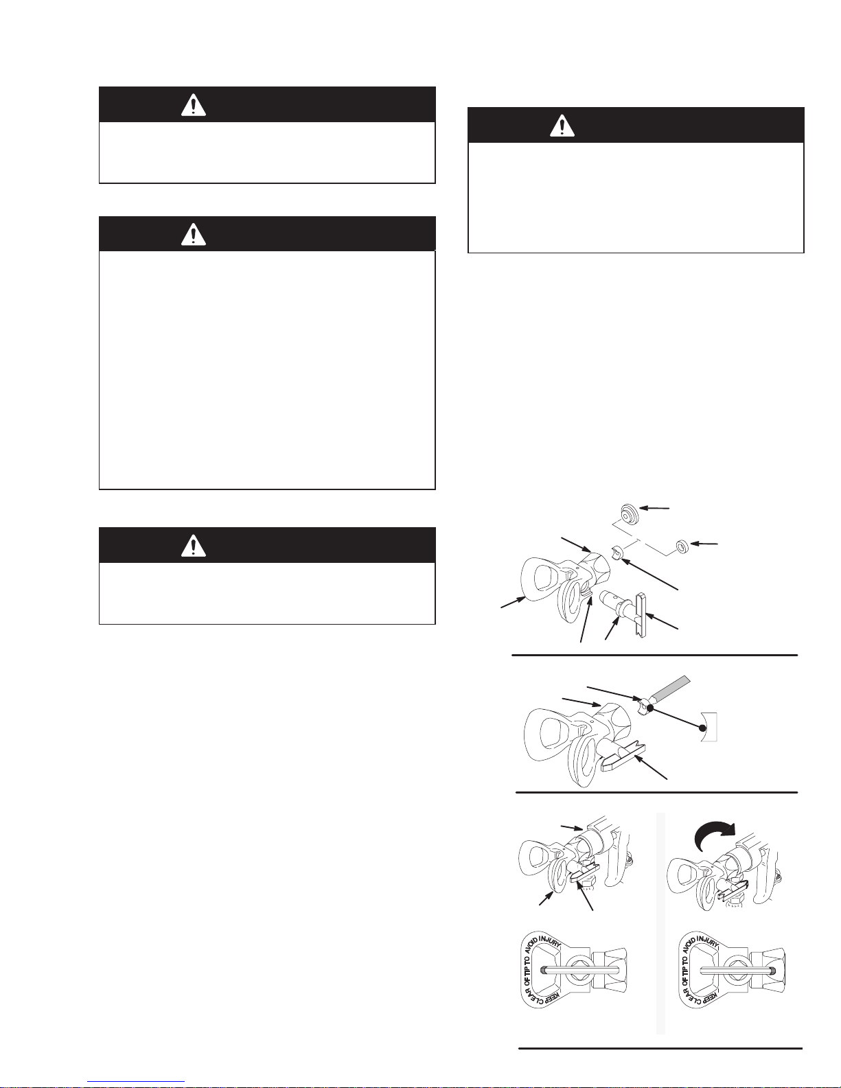
Installation
Relieve pressure. Install a tip (F) so the flange (G) on the
cylinder fits into the slots (H) at the base of the spray tip
guard (J). See Fig. 11.
Be sure the spray tip handle is in the FULL SPRA Y position before operating the gun. See Fig. 11.
Clearing a Clogged Spray Tip
Disengage the trigger cable(s). Engage the gun safety
latch. Turn the arrow handle to the FULL CLEAN position. See Fig. 13. Release the safety latch and trigger the
gun. Fluid pressure should force out the clog. Return the
arrow handle to the full spray position.
clogged
page 7 and remove the spray tip for cleaning.
, follow the Pressure Relief Procedure on
If it is still
Maintenance
Change the seat and gasket when the spray tip wears
out; these parts wear at about the same rate.
C
RED or YELLOW
J
Fig. 11
Fig. 12
GUN NOZZLE
A
E
F
G
H
E
A
F
D
BLACK
0091
0092
Place the seat (E) on a pencil, curved side out, as shown
in Fig. 12. Guide the seat into the retaining nut (A) and
turn the seat until it straddles the cylinder of the spray tip
(F). Drop in the appropriate gasket and press it down. If
using the red or yellow gasket (C), be sure the flat side
faces out of the retainer (A). See Fig. 11.
Screw the spray tip guard snugly onto the gun, holding
it in the desired position while tightening retaining nut (A).
NEVER use a wrench to turn the plastic tip guard (J), to
avoid damaging the guard.
RAC IV
DripLess
TIP GUARD
Fig. 13
TIP
HANDLE
FULL CLEAN POSITIONFULL SPRAY POSITION
0093
15308-082
Page 16

Spray Tip Selection
Spray Tip Application Recommendations
Lineal Feet/Minute
(rate at which unit is moved)
Based on 4” wide line and 15 mils of paint
Application 120 144 184 220 264 308 352 400
Parking Lot Lines
4” wide 217 LLT–317*{ 221* 223 224
6” wide 317 317* 321* 323 325
Long Lines,
4–6” wide 221* 223 225 227 228 231
Curbs 417* 419*
*
Tips can be used with two guns.
Fig. 14
{
Supplied with the Line Lazer.
Spray Techniques
These spray techniques discuss how to use and adjust
the features of the Line Lazer. Y ou must also consider operator technique, job site conditions and weather.
1. Use water rather than paint to practice spraying technique and positioning the guns.
2. Be sure the RAC IV Tip Guard is always parallel to
the ground and the “wings” of the spray tip guard face
the front and back of the unit, as shown in Fig. 15.
8. The spray tip size and the rate at which you move the
unit affect the coating thickness. Generally , the faster you move the unit, the larger the spray tip orifice
should be. The fan width of the spray tip indicates approximately how wide the line will be. See the chart
in Fig. 14 for spray tip application recommendations.
9. Position the guns to suit your requirements. See the
section below and pages 17 to 19.
Other Applications
Sport Court,
2” wide line LLT–213
Crosswalk,
12” wide line, 1 gun 621,
623, 625
Airport,
24” wide line, two guns 721
Stencils 417*, 419*
General Stationary
Painting 517
{
WARNING
To reduce the risk of a fluid injection injury, always
disengage the remote trigger cable to the gun(s)
and engage the gun trigger safety latch(es) before
moving or adjusting the spray tip guards, guns, or
gun arms. See Page 21.
3. Use the lowest pressure necessary for good atomization. High pressure may cause excessive paint
buildup and overspray.
4. Start moving the Line Lazer before triggering the gun
to prevent a build up of paint at the beginning of the
line. Release the trigger a second before stopping
the Line Lazer. Move at an even rate of speed.
5. Always check your gun adjustments on cardboard or
paper before starting each job. When painting curbs,
paint first in an area that is less frequently seen.
6. Keep in mind that many factors affect the straightness of a line, including uneven surfaces, potholes,
rocks and other debris and a clogged or worn spray
tip. See page 15 for how to clear or change a spray
tip.
7. To minimize the ef fect of bumps on the spray pattern,
keep the spray tip guard centered with the front
wheel axis.
16 308-082
10. Traffic paints may be formulated for air spray , airless
spray or have no formulation description.Generally,
air spray formulas are pre–thinned, and will work well
in the Line Lazer, but there may be more overspray.
Non–air spray formulas tend to deliver more lineal
feet of line per gallon with less overspray, since they
are less easily absorbed into the pavement.
1 1. If you use fast–draying traffic paint on a hot day , float
compatible solvent on top of the paint to prevent skin
from forming on it.
Line Width Adjustment
Several factors affect line width: vertical distance of the
spray tip to the spraying surface, spray tip fan pattern, using one or two guns, paint pressure, and a worn or
clogged spray tip.
The typical conditions for a 4 in. wide line are: 317 size
Line Lazer Tip (supplied), the gun positioned one inch
from the lowest vertical position, and just enough pressure to atomize the paint. Depending on the fan pattern
of the spray tip, use one gun to paint 2 to 12 in. wide lines,
and two guns to paint 12 to 24 in. wide lines.
T o decrease line width, lower the gun (if possible) or use
a tip with a narrower fan pattern.
To increase line width, raise the gun, or use a tip with a
wider fan pattern, or use two guns.
Page 17

Positioning the Gun Arm Assembly
PUMP SIDE
1
402
First gun
Second gun
F
Fig. 15
The gun arms can be positioned for a variety of spraying
needs. The drawings on page 19 primarily show the guns
mounted on the pump side of the Linestriper. However,
one or both guns may be mounted on the engine side.
“WINGS” OF TIP GUARD
Whenever You Move the Guns
ENGINE SIDE
D
405B
0012E
B
4
405A
93
404
E
B
A
DETAIL A
D
Horizontal Position of the First Gun
Method 1: Disengage the trigger cable. Loosen the carriage clamps (B,D) and slide the carriage bar (4) left or
right, so the gun will be outside the tire path. Tighten the
clamps. Engage the trigger cable.
CAUTION
Do not kink the cables, which could prevent them
from properly triggering the guns.
Disengage the trigger cables and engage the gun trigger
safety latch first. See page 21. Do not kink the trigger
cables. Pull out more of the 50 ft. hose, if necessary.
After moving the guns, reposition the spray tip guard so
it is parallel to the ground and its “wings” face the front
and back of the unit. Disengage the gun trigger safety
latch and engage the trigger cable.
V ertical Position of the First or Second Gun
Loosen the arm clamp (6) and move the gun up or down.
Tighten the clamp. Engage the trigger cable.
NOTE: See Fig. 15. Two collars (F) are located above
and below each gun. The collars can be adjusted to provide stops for preset spray width positions for each gun.
Method 2: Disengage the trigger cable. Loosen the arm
clamp (6) and rotate the gun out to the side. Tighten the
bolt. Engage the trigger cable.
NOTE: Use methods 1 and 2 together to obtain the maximum distance of one gun from the unit, which is helpful
when spraying around obstacles.
Horizontal Position of the Second Gun
Method 1: Disengage the trigger cable. Loosen the
clamps (405A, 405B). Slide the second gun bar (404)
horizontally, being sure both clamps engage the second
gun bar. Tighten the clamps. Engage the trigger cable.
Method 2: Disengage the trigger cable. Loosen the arm
clamp (6) and rotate the gun out to the side. Tighten the
bolt. Engage the trigger cable.
NOTE: Use methods 1 and 2 together to obtain the maximum distance of 33–1/2 in. (851 mm) between the center
of two guns.
17308-082
Page 18

Positioning the Gun Arm Assembly
Mount Guns on the Engine Side of the Cart
1. See Fig. 15. For both guns, disengage the trigger
cable and engage the trigger safety latch. See page
22.
2. Loosen the gun holder knobs (93) and remove the
gun. Lay the guns out of the way.
3. Remove the knobs (E) on both carriage clamps
(B,D); the carriage bar (4) and extension clamps (A)
will drop down.
4. Lift the front tire and rotate the carriage bar 180 under the cart and to the other side of it.
5. Position the carriage bar below the carriage clamps
(B,D). Align the holes in the top of the extension
clamps (A) with the holes in the carriage bar clamps
and install the knobs (E).
6. Loosen the post/arm clamps (6) and rotate the guns
forward. Retighten the clamps.
7. Install the guns. Note which gun and position on the
dual gun selector each of the cables (1 and 402)
goes. Route the hoses and cables to prevent kinking.
Position the spray tip guards. Disengage the gun trigger safety latches. Engage the trigger cables.
Setup for Spraying Arcs
1. See Fig. 16. Disengage the trigger cable (1) and engage the gun trigger safety latch. See page 21.
2. Loosen the arm clamp (6) and rotate the arm (A)
back near the rear tire and then position the arm so
the spray tip guard aligns with the back axle of the
unit. Retighten the clamp.
3. Extend the carriage bar (4) or second gun bar (404)
so you can easily watch the line you are painting and
also to avoid running over the paint line. See
page 17.
4. Adjust the vertical and horizontal position of the gun.
5. Spray the arc from the outside.
A
6
1
4
Fig. 16
Adjust Simultaneous Gun Triggering
WARNING
To reduce the risk of a fluid injection injury, always
disengage the trigger cable to the gun (s) and
engage the guns’ trigger safety latch before moving
or adjusting the guns or gun arms.
1. Align the front of the guns by adjusting the gun arms.
See page 17.
18 308-082
0002D
2. Position the dual gun selector to trigger both guns.
See page 21.
3. Start the sprayer, using water, or spray on cardboard. See page 13. Trigger the guns to see if the
lines begin at the same time and place.
If one gun triggers before the other gun, reduce the
cable tension of the gun that triggers first. See Ad-
just the trigger cable tension on page 22
If one line starts in front of the other, adjust the position of the guns. See page 17.
Trigger the guns to recheck the adjustments.
.
Page 19

Gun Arm Positions
ONE GUN CURBSINGLE LINE
DOUBLE LINE OR SINGLE LINE UP TO 24” WIDE TWO GUN CURB
SINGLE OR DOUBLE LINE; SPRA YING AROUND OBSTACLES
DOUBLE LINE OR SINGLE LINE UP TO 24”
0017A
WIDE
19308-082
Page 20

Caster Lever and Cable Operation
CAUTION
The AccuTrack caster is factory-adjusted to track
in a straight line. It should not require adjustment
unless it is replaced. If a line is tracking poorly, check
for the following items before aligning the caster.
1. Even back tire pressure.
2. Even tension on the rear tire bearings (adjust
nuts (10) as needed.) See page 40.
3. Even tightness of the caster screws (F). See
Fig. 18.
4. Uneven painting surface.
5. Operator technique.
Operation
Maintenance See Fig. 18
Paint builds up on the caster triggering mechanism. To
keep it operating properly , use a grease gun at the grease
zerks (32A, 32B) to flush out the buildup – two to four
times a month, depending on use.
Caster Tire Replacement See Fig. 18.
Remove the setscrews (F) from the caster fork (E). Remove screw (G) and the tire (114a). Install the new tire
and the setscrews (F). Tighten the setscrews equally so
the tire has no play in it, but turns freely.
Caster Cable T ension Adjustment See Fig. 18.
1. Loosen the nut (A) located just outside the carriage
clamp (B).
2. With the pin (D) fully engaged in the caster fork (E),
pull back on the cable (2) to increase the cable tension, or push it forward to reduce the tension. Finger
tighten the nut (H). Tighten the nut (A) firmly.
The normal operating mode of the AccuTrack caster is
locked in the straight forward position.
1. For a free moving caster: Squeeze and hold the caster lever (22).
2. To lock the caster in the free moving position,
squeeze the trigger, push in and hold the the button
(A) and release the trigger. See Fig. 17.
3. To return to the normal mode, squeeze and release
the caster lever and move the Line Lazer forward to
lock the caster in the straight position.
22
A
Fig. 17
0018
Shown removed only
for visual purposes
Tighten equally so tire
has no play in it but
turns freely
Fig. 18
A
2
32A
114a
G
H
B
D
87
32B
D
E
F
0019
Caster Alignment
Do this adjustment only if the caster or tire is replaced,
or if no other solutions to poor tracking are found.
1. Loosen the two capscrews (87), grasp the tire and
visually align it. Tighten the capscrews evenly . Move
the unit forward. If the caster appears straight, start
the unit (use water) and spray along a true straight
line. Continue adjusting as necessary. See Fig. 18.
How To Mount the Gun
1. Relieve pressure. See page 7.
2. Disengage the trigger cable. See page 21. Engage
the gun’s trigger safety latch (B).
3. Loosen the gun holder knob (93).
4. Position the gun so the gun trigger is resting on the
remote trigger lever (A).
5. Be sure that the gun is mounted straight and then
tighten the knob (93) firmly.
6. Disengage the gun safety latch. Engage the remote
trigger cable. See page 21.
20 308-082
Fig. 19
95
93
B
A
0020B
Page 21

Gun Cable & Dual Gun Selector Operation
Shown in
three positions
A
B
118d
1 or 402
Fig. 20
C
0021
How the Dual Gun Selector Works See Fig. 20.
The gun is remotely triggered with the dual gun selector
on the right handlebar . The gun is mounted in the holder
so its trigger rests on a trigger lever which is connected
to the dual gun selector by a trigger cable.
The main gun cable is black. In a two–gun operation, the
second gun cable (402) is black with a light red cover at
each end. Use the color coding to determine how each
trigger cable is routed to the dual gun selector.
How to Release the Dual Gun Selector
Cable
WARNING
The gun is remotely triggered with a dual gun
selector on the handle bar.
To reduce the risk of an injection injury due to
remotely triggering the gun by accident, always
disengage the trigger cable from the block before
handling the gun. See Fig. 21 DETAIL A. The gun
will trigger briefly when releasing the cable!
Before you remove the gun from the holder, engage the gun’s trigger safety latch.
1. To disengage the cable, grasp the cable (1or 402)
just behind the block (48). Pull the cable back about
1/2 inch (13 mm) and then up and out of the block.
The gun will trigger briefly! See Fig. 21.
2. To engage the cable, slide the cable (1) into the block
(48), making sure the end of the cable jacket seats
firmly in the seat of the block. The gun will trigger
briefly! See Fig. 21.
CAUTION
Always note to which gun and position on the dual
gun selector (C) each of the cables goes so that the
correct gun is triggered.
T o trigger the main gun only, move the selector (C) left until the spool (118d) protrudes through the plate (B) and
disengages from the other plate (A).
To trigger the optional second gun only, move the selector (C) right until the spool protrudes through the plate (A)
and disengages from the other plate (B).
To trigger both guns, center the selector (C).
CAUTION
Keep the seat in the gun cable block (48) and the
end of the cable jacket clean at all times to be sure
the cable functions properly.
CAUTION
A loose cable prevents the gun from being fully
triggered causing premature wear of the gun needle.
A tight cable prevents the full trigger release of the
gun resulting in dripping and premature tip wear.
Follow Trigger cable tension adjustment on page
22.
21308-082
Page 22

Trigger Cable & Dual Gun
Selector Operation
Trigger Cable Tension Adjustment See Fig. 21
1. Relieve pressure. See page 7.
2. Be sure the gun is properly mounted in the holder as
instructed on page 20.
3. Pull the actuator lever (94) forward and hold it. Lift up
on the gun trigger (A) until there is slight resistance.
Visually check to see if there is about 1/32 to 1/16 in.
gap between the trigger lever (B) and where the gun
trigger touches the bar.
4. To adjust the tension, loosen the screw (C) in the
block (48). Slide the block forward to increase the
gap and backward to decrease the gap. Tighten the
screw.
5. Recheck the gap and adjust as needed.
CAUTION
Do not allow the cable (402) to rub against the
outside edges of the slot (H) in the block (48), to
prevent premature wear of the cable. Rotate the
block slightly to eliminate rubbing. See Fig. 21
DETAIL A.
FORWARD
DETAIL A
48
Fig. 21
1 or 402
94
A
48
C
45
45
1/32 – 1/16”
(1–2 mm)
0023
0024
B
Be sure end jacket of cable
seats here. keep jacket and
seat clean
1 or 402
22 308-082
Page 23

WARNING
Maintenance
After the first 20 hours of operation and each 100
hours thereafter: Change the oil.
To reduce the risk of serious injury always follow
the Pressure Relief Procedure on page 7,
before checking, adjusting, cleaning, or shutting
down the LineLazer.
CAUTION
For detailed engine maintenance and specifications,
refer to the separate HONDA engine manual.
Daily: Check the engine oil level and fill as necessary.
Daily: Check and fill the gas tank.
1
Weekly: Remove the air filter cover and clean the element. In very dusty environments, check the filter daily.
Replace the element as needed. Replacement elements
can be purchased from your local HONDA dealer.
Weekly: Check the level of the TSL in the displacement pump packing nut. Fill the nut, if necessary. Keep
TSL in the nut to help lubricate the pump packings. See
page 8.
Weekly: Use a grease gun to grease the zerks (32) on
this unit. The grease purges pivot areas of paint buildup.
See Fig. 22.
Spark plug: Use only a (NGK) BP6ES or BPR6ES
plug. Gap the plug to 0.025 to 0.030 in. (0.7 to 0.8 mm).
Always use a spark plug wrench.
One zerk on dual gun selector
1
2
One zerk on each gun holder
3
One zerk on caster lever
4
One zerk on caster latch
One zerk on wheel
5
Fig. 22
3
4
2
5
23308-082
Page 24

Troubleshooting
WARNING
To reduce the risk of serious injury whenever you
are instructed to relieve pressure, always follow the
Pressure Relief Procedure on page 7.
Check everything in the chart before disassembling the sprayer.
PROBLEM CAUSE SOLUTION
Engine/sprayer won’t start Engine switch not on Turn on engine switch.
Out of gas Refill gas tank.
Engine oil level low Try starting engine. If light on rear of engine
Spark plug cable disconnected or
spark plug damaged
Water frozen in pressure control Return pressure control to authorized Graco
Engine won’t “fire” Oil seepage into combustion
Engine operates, but displacement
pump doesn’t
chamber
Pressure control switch turned OFF Turn on pressure control switch.
Pressure setting too low Increase pressure.
Displacement pump outlet filter dirty Clean filter.
Tip or tip filter clogged Clean tip or tip filter.
Displacement pump rod seized by
dry paint
Connecting rod worn or damaged Replace connecting rod. See page 28.
Drive housing worn or damaged Replace drive housing. See page 29.
Electrical power not energizing field Check wiring connections. See page 34.
glows, replenish oil.
Connect cable on top of engine or replace spark
plug.
dealer for repair.
Remove spark plug. Pull starter rope 3 or 4 times.
Clean and replace plug. Try to start. Keep sprayer upright to avoid oil seepage.
Service pump. See page NO TAG.
With pressure control switch ON and pressure
turned to MAXIMUM, use a test light to check
continuity across black and white wires from
pressure control.
Have pressure control checked by authorized
Graco dealer.
Clutch worn or damaged Service clutch. See page 32.
Pinion assembly worn or damaged Service pinion assembly. See page 30.
Engine starts but dies Oil level drops below oil sensor Add oil.
Displacement pump output low on
upstroke
Pump inlet screen clogged Clean screen.
Piston ball check not seating Service piston ball check. See page NO TAG.
Piston packings worn or damaged Replace packings. See page NO TAG.
Sleeve gasket in displacement pump
worn or damaged
24 308-082
Replace sleeve gasket. See page NO TAG.
Page 25

Troubleshooting
PROBLEM CAUSE SOLUTION
Displacement pump output low on
downstroke or both strokes
Paint leaks into wet–cup Loose wet–cup Tighten wet–cup just enough to stop leakage.
Spitting from gun Air in fluid pump or hose Check for loose connections at pump intake and
Pump inlet screen clogged Clean screen.
Pressure setting too low Increase pressure. See Startup,
Dirty outlet filter , tip filter or tip Clean filters and/or tips.
Piston packings worn or damaged Replace packings. See page NO TAG.
Intake valve ball check not seating
properly
Engine RPM too low Increase throttle setting. See Startup,
Clutch worn or damaged Replace clutch. See page 32.
Partially clogged suction tube assembly Remove and clean suction tube. During normal
Large pressure drop in hose Use larger diameter hose.
Throat packings worn or damaged Replace packings. See page NO TAG.
Displacement rod worn or damaged Replace displacement rod. See page NO TAG.
Step 14, page 13.
Clean and service intake valve. See page
NO T AG.
Steps 5b and 14, page 13.
flushing remove and clean the suction tube assembly separately to prevent further clogging.
tighten. Them prime the pump.
See Startup, page 13.
Tip partially clogged Clear tip clog. See page 15.
Fluid supply is low or empty Refill and prime the pump. See Startup, page 13.
Dried paint particles from a poorly cleaned
suction tube assembly
Check fluid supply often to prevent running the
pump dry.
Remove and clean suction tube. During normal
flushing remove and clean the suction tube as-
sembly separately to prevent further clogging.
25308-082
Page 26

Pressure Control
WARNING
To reduce the risk of serious injury whenever you
are instructed to relieve pressure, always follow the
Pressure Relief Procedure on page 7.
1. Disconnect both hoses (133) at the pressure control
swivel unions (108). Note the original location of
each hose to be sure you reassemble them correctly
at the end of this procedure. See Fig. 23.
2. Working under the engine mounting plate of the cart,
disconnect the pressure control wires at A. Remove
the four nuts (40) and related hardware from the
capscrews (91 & 87).
3. Remove the pressure control covers (89). See Fig.
23.
4. Disconnect the red, black and white wires from the
rectifier (307) which are sheathed with the conductor
(309). Unscrew the connector (313) from the pressure control, pulling the conductor and wires out with
it. See Fig. 24.
5. Use a wrench to hold the hex of the adapters (C)
while removing the swivel unions (108). See Fig. 24.
W ARNING
To reduce the risk of electric shock, be sure all
grounding features of the pressure control are
properly assembled:
Ground wire (308) connected in pressure con-
trol.
Serrated flange capscrews to mount the pres-
sure control to the cart.
Grounding chain (106) connected by the long
pressure control mounting capscrew (87).
6. Reassemble the pressure control in the reverse order. Use the long pressure control mounting screw
(87) in hole B. From below the mounting plate (25)
assemble the grounding chain (106), washer (105)
and nut (40) to the screw. See Fig. 23.
7. Perform the Pressure Control Adjustment on
page 27 before regular operation of the sprayer.
106
105
40
TO ENGINE
108
WHITE
RED
109
B
91,87
309
89
309
40
307
313
BLACK
C
RECTIFIER (307) CONNECTIONS
A
~
BLACKRED
-
0033
TO FIL TER
Fig. 23
TO PUMP
26 308-082
133
0032
Fig. 24
+
WHITE
~
GROUND
0034
Page 27

Pressure Control Adjustment
WARNING
Use extreme caution when performing this calibration procedure to reduce the risk of a fluid injection in-
jury or other serious bodily injury , which can result from
component rupture, electric shock, fire, explosion or
moving parts.
This procedure sets the sprayer to 2600–3000 psi
(190–210 bar, 19.0–21.0 MPa) Maximum Working
Pressure.
Perform this procedure whenever the pressure control
assembly is removed and reinstalled, or replaced, to be
sure the sprayer is properly calibrated.
Improper calibration can cause the sprayer to over–
pressurize and result in component rupture, fire or ex-
plosion. It may also prevent the sprayer from obtaining
the maximum working pressure, resulting in poor
sprayer performance.
NEVER attempt to increase the fluid outlet pressure by
performing these calibrations in any other way. Never
Exceed 3000 Psi (210 Bar, 21.0 MPa) Maximum
Working Pressure. Normal operation of the sprayer at
higher pressures could result in component rupture,
fire or explosion.
AL WA YS use a
new
50 foot (15.2 m) spray hose, rated
for at least 3000 psi (210 bar, 21.0 MPa) Maximum
Working Pressure, when performing this procedure. A
used, under–rated hose could develop a high pressure
leak or rupture.
Service Tools Needed:
New 50 foot (15.2 m), 3000 psi (210 bar, 21.0 MPa),
flexible nylon airless spray hose, Part No. 223–541
0–5000 psi (0–345 bar, 34.5 MPa) fluid–filled pressure
gauge,
Part No. 102–814
New spray tip, size 0.025 to 0.029
3/8 in. ignition wrench or nut driver
5 gallon pail of water or mineral spirits
Swivel, 156–823
Nipple, 162–453
Tee, 104–984
Set Up
1. Follow the Pressure Relief Procedure Warning on
page 7.
2. Set up the system as shown in Fig. 25.
Set the Dead Band (Pressure Differential)
1. Remove the pressure control cover.
NOTE: Do not alter this adjustment if the wheel is already
set as shown in Fig. 26.
2. Set the white differential wheel (A) on the microswitch. Turn the wheel so the letter F is concealed
behind the switch and the letter E is the first letter
seen.
Fig. 25
Inside pressure
control looking up
at differential wheel
Fig. 26
102–814
156–823
104–984
162–453
223–541
0035
A
0036
Pressure Up
1. Start the sprayer and prime it.
2. Adjust the pressure to 2600 psi (180 bar, 18.0 MPa).
3. Shut off the engine. If the pressure drops after the engine is shut off, replace the pump packings before
proceeding. See page NO TAG.
Adjust the Pressure
1. Remove the plug (320) in the bottom of the control.
2. Turn and hold the pressure control knob (B) at the
maximum pressure.
3. Engage the nut (C): Insert the nut driver through the
pressure control hole (D), or use an ignition wrench
inserted from the front of the pressure control.
See Fig. 27.
D
B
320
Fig. 27
C
0037
a. Loosen the nut just until you hear a click. Stop.
b. Slowly tighten the nut just until another click is
heard. Stop.
4. Replace the plug (320) and the pressure control
cover.
27308-082
Page 28

Bearing Housing and Connecting Rod
WARNING
To reduce the risk of serious injury whenever you
are instructed to relieve pressure, always follow the
Pressure Relief Procedure on page 7.
NOTE: Steps 1 to 10 refer to Fig. 28.
9. Install the screws (81) and lockwashers (46) on the
bearing housing. Tighten the screws evenly to 175
in–lb (20 N.m).
10. Refer to Installing the pump on page NO TAG.
T orque to 175 in–lb (20 N.m)
1. Refer to Removing the Pump on page NO TAG.
2. Remove the four screws (81) and lockwashers (46)
from the bearing housing (76).
3. While pulling the connecting rod assembly (79) with
one hand, lightly tap the lower rear of the bearing
housing (76) with a plastic mallet to loosen it from the
drive housing (77). Pull the bearing housing and the
connecting rod assembly off the drive housing.
4. Inspect the crank (A) for excessive wear and replace
parts as needed.
5. Evenly lubricate the inside of the bronze bearing (D)
in the bearing housing (76), and the inside of the connecting rod link (C), with high–quality motor oil. Liberally pack the roller bearing (B) in the connecting rod
assembly (79) with bearing grease (77d), supplied.
6. Assemble the connecting rod (79) and bearing housing (76).
7. Clean the mating surfaces of the bearing and drive
housings.
8. Align the connecting rod with the crank (A) and carefully align the locating pins (E) in the drive housing
(77) with the holes in the bearing housing (76). Push
the bearing housing onto the drive housing or tap it
into place with a plastic mallet.
81,46
59
73
72
74
80,59
15
71
79
77
B
C
A
E
D
76
75
137
54
CAUTION
Do not use the bearing housing screw (81) to align or
seat the bearing housing with the drive housing.
These parts must be aligned using the locating pins
(E) to help avoid premature bearing wear.
28 308-082
Fig. 28
53
0038A
Page 29

Drive Housing
WARNING
To reduce the risk of serious injury whenever you
are instructed to relieve pressure, always follow the
Pressure Relief Procedure on page 7.
NOTE: Refer to Fig. 29 for this procedure.
1. Remove the front cover (74).
2. Disconnect the pump outlet hose (133).
3. Remove the four screws (81) and lockwashers (46)
from the bearing housing (76).
4. Lightly tap the back of the bearing housing (76) with
a plastic mallet. Pull the pump, bearing housing and
connecting rod away from the drive housing as one
assembly.
5. Remove the two bearing housing screws (80) and
lockwashers (59). Remove the four pinion housing
screws (67) and lockwashers (59).
6. Lightly tap around the drive housing (77) with a plastic mallet to loosen it from the pinion housing (138p).
CAUTION
Do not drop the gear cluster (78) when removing the
drive housing (77). The gear cluster is easily damaged. The gear may stay engaged in either the drive
housing or the pinion housing.
Do not lose the thrust balls (77c and 138k) located at
each end of the gear cluster. The balls, which are
heavily covered with grease, usually stay in the shaft
recesses, but they could be dislodged. If they are
caught between the gears and not removed, the balls
will seriously damage the drive housing. If the balls
are not in place, the bearings will wear prematurely.
7. Liberally apply bearing grease (77d, supplied) to the
gear cluster (78). Be sure the thrust balls (77c and
138k) are in place.
8. Place the bronze colored washer (77a) and then the
silver–colored washer (77b) on the shaft protruding
from the big bearing of the drive housing (77). Align
the gears and push the new drive housing straight
onto the pinion housing and locating pins (B).
9. Starting at Step 5, work backwards to reassemble
the sprayer. Or, move ahead to the next section in
this manual if further service is needed.
67
59
T orque to 175 in–lb (20 N.m)
74
73
133
76
79
B
138p
77b
77a
77
67
59
138k
78
77c
59
80
46
81
Fig. 29
0039A
29308-082
Page 30

Pinion, Clutch, Clamp, Field, & Engine
Disassembling these parts can start from the pinion
housing or from the clutch, if no pinion service is
needed.
Pinion Housing
Removing the Pinion Housing
WARNING
To reduce the risk of serious injury whenever you
are instructed to relieve pressure, always follow the
Pressure Relief Procedure on page 7.
NOTE: Refer to Fig. 30 for Steps 1 to 3.
1. Remove the two bottom screws (67) first, and then
remove the top three screws (67).
2. Pull the pinion housing (138p) away from the clutch
housing (61). The armature (55a) will come with it.
3. Pull out the armature (55a).
CAUTION
If starting from the pinion housing
1 to 6 of DRIVE HOUSING, on page 29, and then contin-
ue with the procedure below.
If starting from the clutch
2. Push on the front of the shaft (138b) to force the
bearing and hub assembly out of the housing
(138p).
3. Install the new shaft assembly (138a), pushing it to
the shoulder of the pinion housing (138p).
4. Install the rings (138e and 138m).
5. Skip ahead to Reassembly, page 37, Step 7, or
continue on page 32.
See page 31
, see page 32.
, first follow Steps
Do not lose the thrust ball (138k). Refer to the CAU-
TION on page 29 for more information.
NOTE: To disassemble the pinion, continue with Repair-
ing the Pinion, below. To disassemble more of the
sprayer, go to page 32. To reassemble the sprayer from
this point, skip ahead to Reassembly, page 37, Step 8.
Repairing the Pinion
NOTE: A hydraulic press is required for disassembly and
reassembly if you purchase the pinion parts individually.
If you do not have such a press, use Repair Kit No.
223–189, which includes the shaft and bearings pre–assembled and lubricated.
NOTE: Refer to Fig. 31 except where noted.
If using Repair Kit 221–032, follow steps 1 to 5 below.
1. Remove the small ring (138e) from the hub (138f)
and the large ring (138m) from the bearing recess
of the pinion housing (138p).
Fig. 30
55a
61
138k
59
67
138p
67
59
0040
30 308-082
Page 31

Pinion Housing
0041
DETAIL A
CUTAWAY VIEW OF PINION
HOUSING (138p)
Fig. 31
138p
2
3
1
138h
138k
Back of pinion housing
1
Press fit small bearing (138c) and roller clutch (138g) in here
2
Lubricate exterior
3
Lubricate inner and outer diameters
4
5
Lubricate teeth
138m
138a
138n
138c
138j
3
138g
4
138b
138d
5
138f
138e
4
0042
If you purchased parts separately, use the following instructions. Disassemble only as far as needed for the
parts being replaced.
NOTE: The old bearing (138d) will be damaged when removed. Have an extra one on hand if you need to remove
it for any reason.
1. If replacing the small bearing (138c) or roller clutch
(138g), press the old ones out of the pinion housing (138p).
2. Remove the small ring (138e) from the hub (138f).
Remove the snap ring (138m) from the bearing
recess of the housing (138p).
3. Push on the front of the shaft (138b) to force the
bearing and hub assembly out of the housing
(138p).
6
Round steel bar to
1
push on shaft (138b)
2
Large bearing
Hub
3
Steel bar stock
4
Two steel blocks
5
Hydraulic press
6
7
Press platform
2
1
138d
138f
3
4
5
4.
Using a hydraulic press,
place pieces of steel
bar stock on the inner race of the large bearing
(138d) and press the shaft through the hub and
bearing. See Fig. 31.
5. Apply lubricant to the parts as shown in Fig. 31.
CAUTION
The arrow on the roller clutch (138g) must point
toward the small bearing (138c) for the shaft (138b)
to rotate in the right direction.
6. Press fit the following parts:
Small bearing (138c) and then the roller clutch
(138g), with its arrow pointing to the bearing,
into the rear of the housing (138n). See Detail A
in Fig. 31.
Large bearing (138d) to the shoulder of the shaft
(138b).
Hub (138f) onto the shaft (138b) all the way to
the large bearing (138d).
7. Install the shaft assembly (138a), pushing it to the
shoulder of the housing (138p).
PLACEMENT OF STEEL BLOCKS AND BAR
Fig. 32
STOCK WHEN PRESSING OFF LARGE BEARING
7
0043
8. Install the rings (138e and 138m).
9. Skip ahead to Reassembly, page 37, Step 7, or
continue on the next page.
31308-082
Page 32

Clutch
NOTE: The clutch assembly (55) includes the armature
(55a) and rotor (55b). The armature and rotor must be replaced together so they wear evenly.
NOTE: If the pinion assembly (138) is not yet separated
from the clutch housing, follow Steps 1 to 4. Otherwise,
start at Step 5.
1. Follow the Pressure Relief Procedure Warning on
page 7.
2. Disconnect the hose (133) from the displacement
pump.
3. Remove the bottom two screws (67) from the clutch
housing (61) and then remove the remaining three
screws (67).
Torque to 7 ft–lb (9.5 N.m)
Pinion shaft
Threaded holes
55b
156
157
55a
4. Tap lightly on the back of the drive housing (77) with
a plastic mallet to loosen the assembly (D) from the
clutch housing (61). Pull the assembly away; the armature (55a) will come with it.
5. Remove the armature from the pinion shaft.
6. Remove the four socket head capscrews (157) and
lockwashers (156). Install two of the screws in the
threaded holes in the rotor (55b). Alternately tighten
the screws until the rotor comes off. See Fig. 33.
7. Skip ahead to Reassembly, page 37, Step 6, or continue on the next page.
67
59
61
Fig. 33
133
D
A
B
138
C
77
USE A STEERING WHEEL
PULLER TO REMOVE ROT OR
0044A
32 308-082
Page 33

Engine
1. Working under the mounting plate (25) of the cart, remove the screw (51), lockwasher (132) and washer
(50) which hold the clutch housing (61) to the cart.
See Fig. 34.
2. Still working under the mounting plate, remove the
two locknuts (40), and then pull the screws (63) out
of the base of the engine. Disconnect the red wire
from the engine lead. Disconnect the black and white
wires (58) from the field. Pull the wires carefully
through the grommets before removing the engine.
See Fig. 34 and 35.
67
59
61
3. Lift the engine carefully and place it on a work bench.
4. Remove the Field and Wiring Harness, Clamp and
Clutch Housing, as instructed on pages 34 and 35.
5. Skip ahead to Reassembly, page 36, Step 1.
NOTE: All service to the engine must be performed by
an authorized HONDA dealer.
TO FIELD
104
25
50
132
51
Fig. 34
40
63
0045
TO ENGINE
Fig. 35
RED
58
View from under engine mounting plate
0032
33308-082
Page 34

Field & Wiring Harness
NOTE: Refer to Fig. 36.
1. Loosen the four setscrews (62) holding the field (70)
to the clutch housing (61). Unplug the wiring harness
(58) from under the engine mounting plate. Pull the
field out to expose the black and white wires (58).
62
61
70
2. Pull the caps (A) off the wire screws (57) in both
places on the field. Loosen the screws and release
the wires (58).
3. Skip ahead to Reassembly, page 36, Step 4.
57
Fig. 36
34 308-082
58
A
0046
Page 35

NOTE: A standard steering wheel puller is required to remove the clamp. Two 1/4–28 x 3 or 4
in. long screws are also needed.
NOTE: Refer to Fig. 37.
1. Loosen the two screws (60) on the clamp (68),
working through the slot at the bottom of the
clutch housing (61).
2. Install two screws (B) of the tool (A) in two of
the threaded holes in the clamp. Tighten the
screws (C) until the clamp comes off.
3. Skip ahead to Reassembly, page 36, Step 3,
or continue below.
Clamp
61
B
C
A
60
Clutch Housing
NOTE: Refer to Fig. 38.
1. Remove the four capscrews (156) and lockwashers (157) which hold the clutch housing
(61) to the engine (64).
2. Remove the engine key (66).
3. Pull off the clutch housing (61).
4. Skip ahead to Reassembly, page 36,
Step 1.
T orque to 125 in–lb (14 N.m)
Fig. 37
61
157
156
68
0047
64
66
Fig. 38
0048
35308-082
Page 36

Reassembly
1. Install the clutch housing (61), capscrews (156)
and lockwashers (157) on the engine. See Fig. 39.
2. Install the engine shaft key (66). See Fig. 39.
3. Install the clamp (68) onto the engine shaft (A).
Maintain the 1.41 in. +/– 0.01 (35.8 mm) dimension
shown in Fig. 40.
To check the dimension, place a rigid, straight steel
bar (B) across the face of the clutch housing (61).
Use an accurate measuring device to measure the
distance between the inside of the bar and the face
of the clamp. Adjust the clamp as necessary. Torque
the two screws (60) to 125 in–lb (14 N.m).
4. Connect the wires of the harness (58) to the screws
(57) in both places on the field. Pull the plastic caps
(C) up and snap them over the screws. Guide the
wires of the harness (58) through the slot in the clutch
housing. Slide the field (70) into the clutch. Align the
setscrew chamfers in the field and the clutch housing
(61). Tighten the setscrews (62) oppositely and
evenly, to 25 in–lb (2.8 N.m). See Fig. 39.
T orque oppositely and evenly
to 25 in–lb (2.8 N.m)
Connect wiring harness (58) here before
sliding field (70) into housing (61)
T orque to 125 in–lb (14 N.m)
Face of housing
1.41” (35.8 mm)
T orque to 125 in–lb (14 N.m)
61
B
A
60
68
70
Fig. 39
156
157
61
66
A
Fig. 40
SIDE CUT AW AY VIEW OF CLUTCH HOUSING
0050
62
58
C
60
57
0049
36 308-082
Page 37

Reassembly
5. Place the engine (64) assembly on the cart. Align
the mounting holes. Guide the engine wire (A)
through the clamp at the the rear of the mounting
plate (25). See Detail A. Guide the wiring harness
(58) from the field, through the grommet (24) in the
mounting plate (25). Install the serrated flange
screws (63) and nuts (40) and torque to 15 ft–lb (20.4
N.m). Install the capscrews (51), lockwashers (132)
and washer (50) from under the engine mounting
plate to secure the clutch housing (61). Connect the
engine wire (A) to the red wire, and connect the black
and white wires of the pressure control at B as
shown in the Detail A, Fig. 41.
NOTE: With the autogap style armature, the gap
between the rotor and the armature is critical for
proper operation. The clutch kits with an autogap style
armature include a cardboard spacer (p/n 186–857) to
set the proper gap. This spacer is used only during
operation.
6. Clean the face of the armature (55a). With the flat
side of the armature facing the rotor (55b), slide the
armature onto the hub (138f) in the drive/pinion assembly just until the chamfered end of the hub (138)
protrudes through the armature. See Detail B, Fig.
41. There will be significant resistance. Attach the
cardboard spacer, supplied with the clutch kit, to the
face of the armature. Engage the tabs on the spacer
with the slots in the armature.
Brace the cart against a wall to keep it from rolling.
Push the drive/pinion assembly onto the clutch
housing (61). There will be significant resistance.
When the mating surfaces of the drive/pinion
assembly and the clutch housing are flush, remove
the drive/pinion assembly. Remove the card-
board spacer.
7. Be sure the face of the rotor (55b) and the field (61)
is free of all oil and contaminants. Install the rotor,
lockwashers (59) and capscrews (60). Torque the
capscrews to 7 ft–lb (9.5 N.m). See Fig. 41
After installing the rotor (55b), pull the engine recoil
rope to assure that the engine turns freely , and there
is no friction between the rotor and the field (61). If
there is friction, loosen the setscrews (62) and reposition the field (61) as necessary. Tighten the setscrews oppositely and evenly to 25 in-lb (2.8 Nm).
Also make sure there are no burrs on the outside
edge of the rotor.
8. Assemble the drive/pinion housing (C) to the
clutch housing, using the capscrews (67) and lockwashers (59). See Fig. 41.
37308-082
Page 38

Reassembly
DETAIL B
138f
0051
Chamfered end of hub
1
Torque to
2
7 ft–lb (9.5 N.m)
Face must be clean
3
Tighten oppositely and
evenly torque to
4
25 in–lb (2.8 N.m)
Torque to
5
15 ft–lb (20.4 N.m)
1
55a
138n,138k
0052A
64
67
59
61
62
4
70
55b
59
2
60
63
58
25
24
50
132
51
40
5
55a
3
DETAIL A
C
VIEW FROM UNDER ENGINE
MOUNTING PLATE
Fig. 41
T o field
T o engine
A
T o pump
To filter
B
0060
38 308-082
Page 39

Parts –Pressure Control
Part No. 222–369 – Replacement Pressure Control for All GM 3500 Sprayers
Part No. 222–369 includes all items marked with a [. It does not include unmarked items. Order the Basic Control,
222–369, and/or items 309 or 313 as needed.
Ref.
No. Part No. Description Qty.
300[ 222–380 PRESSURE CONTROL
Includes items 302 to 304
301[ 183–466 LABEL, caution 1
302[ 1 1 1–930 ON/OFF SWITCH 1
303[ 105–659 BOOT, switch 1
304[ 107–255 GUARD, locking 1
305[ 157–021 LOCKWASHER, No. 8, internal 2
306[ 100–284 NUT, hex, 8–32 1
308[ 220–979 CONDUCTOR, red 2
309 220–978 CONDUCTOR, red, white, black 1
ENGINE
RED
ADJUSTABLE
PRESSURE
SWITCH
MAIN
SWITCH
RED
310[
305[
WHITE
Ref.
No. Part No. Description Qty.
310[ 100–035 SCREW , mach, slotted pan hd,
1
8–32 x .312” 1
311[ 108–783 SCREW , mach, flat hd; 8–32 x .812” 1
313 108–852 CONNECTOR, 45_ 1
316[ 222–352 TRIAC 1
317[ 107–070 SCREW , flat head, 6–32 x .625 2
318[ 100–072 NUT, hex, 6–32 2
319[ 103–181 LOCKWASHER, No. 6, external 2
320[ 101–754 PLUG, pipe, 3/8 npt 1
317[, 318[, 319[
316[
308[
RED
302[
303[
304[
RED
C
NO
WHITE
R
RECTIFIER
BLACK
CLUTCH
FIELD
G
GROUND
REDRED
WIRING SCHEMATIC
MT2
MT1
RED
WHITE
CLUTCH
FIELD
308[
RED
313
309
320[
RED BLACK
~
+
WHITE
RECTIFIER (307) CONNECTIONS
-
~
GROUND
311[,
305[,
306[
307[
BLACK
301
LABEL
300[
0033
0034
39308-082
Page 40

Parts – Cart
21
118
150
193
194
20
22
Ref 13
195
83
168
3
84
169
23
171
1
1
159
86
170
82
52
REF 3
34
172
4
90
2
39
40
28
24
33
32
33
139
27
35
94
99
36
E
29
37
11
See page 41
1
2
Label
See page 44
3
4
See page 42
10
30
A
19
40
40
26
42
104
41
2
26
110
117
39
25
30
87
38
185
42
41
2
40
31
39
114
116
115
184
E
112
A
183
3
32
105
40
40 308-082
186
114a
10
114d
114e
114c
114b
0003F
Page 41

Parts – Cart
Model 231–132, Series A With one gun
Includes items 1–195
Ref.
No. Part No. Description Qty.
1 1 11–154 CABLE, dual gun selector,
2 240–484 KIT, hose, linestriper 1
3 1 11–153 CABLE 1
10 1 12–405 NUT 3
1 1 111–020 WHEEL, pneumatic, 16” dia. 2
19 224–021 HANDLE 1
20 108–063 GRIP, handle 2
21 186–787 BRACKET, release lever 1
22 1 11–197 LEVER, release 1
23 224–246 COVER, pail 1
24 109–099 BUSHING, snap 2
25 186–672 PLA TE, mounting 1
26 1 11–040 LOCKNUT, 5/16–18 w/nylon insert 4
27 1 10–963 SCREW, serrated flange, hex hd,
28 106–212 CAPSCREW, hex hd, 3/8–16 x 2–
29 104–766 MOUNT, motor 4
30 108–471 KNOB 2
31 186–668 BRACKET, rear caster 1
32 100–846 FITTING, lubrication 1
33 1 1 1–016 BEARING, flanged 2
34 1 11–230 SCREW, mach, flhd,1/4–20 x 1” 1
35 100–015 NUT, hex, 1/4–20 1
36 186–814 PIN, pivot 1
37 103–262 CAPSCREW, sch, 5/16–18 x 3–
38 186–731 BRACKET, front caster 1
39 1 11–194 CAPSCREW, serrated flange hd,
40 101–566 LOCKNUT, 3/8–16 w/nylon insert 16
41 186–821 LABEL, Warning (trigger cable) 2
42 224–136 CLAMP, extension 2
52 103–927 CLAMP, hose, 1–1/4” 1
82 183–769 TUBE, suction, 5 gal, 3/4” pipe 1
83 178–342 CLIP, spring 5
84 238–959 HOSE, cpld, 3/16” x 60” 1
85 103–473 WIRE TIE STRAP 3
86 176–920 HOSE, suction 1
87 1 11–193 CAPSCREW, serrated flange, hex hd,
90 183–770 STRAINER, 16 mesh 1
94 186–747 LEVER, actuator 1
99 101–345 NUT, hex, jam, 1/4–20 1
104 108–868 CLAMP , wire 1
105 100–731 WASHER, 3/8” 2
107 186–620 LABEL, grounding 1
1 10 224–019 CART 1
9.6 ft (2.9 m) 1
5/16–18 x 3/4” 1
3/8–16 x 2” 6
3/8–16 x 7/8” 2
3
/4”4
1
/2”1
REMOTE TRIGGER DETAIL,
Ref No. 118, Includes 118a–118e
Model 231–140 With two guns
Includes items 1–195, and 401–405
Ref.
No. Part No. Description Qty.
1 12 224–066 CASTER LATCH ASSY
1 14 238–052 SWIVEL CASTER
1 14a 1 12–820 SCREW, cap, hex hd 1
1 14b 112–822 BEARING, needle 1
1 14c 112–823 RACE, needle 1
1 14d 112–824 SEAL 1
1 14e 112–825 SPRING, Belleville
1 15 801–020 NUT, 1/2–13 w/nylon insert 4
1 16 101–044 WASHER, flat, 1/2” 4
1 17 111–195 CAPSCREW, serrated flange, hex hd,
1 18 224–144 REMOTE TRIGGER KIT
1 18a 111–018 .SPRING, compression 1
1 18b 11 1–206 .BEARING, ball, 3/32” 1
1 18c 186–746 .TRIGGER 1
1 18d 186–694 .SPOOL, cable selector 1
1 18e 186–832 .KNOB 1
1 19 186–695 BLOCK, mounting 1
120 190–098 PIN, trigger pivot 1
121 111–017 BEARING, flanged 2
122 186–696 PLATE, lever 2
127 107–110 LOCKNUT , with nylon insert,
139 107–194 WASHER, flat 3/8” 1
147 206–994 THROAT SEAL LIQUID, 8 oz (0.27 l) 1
150 112–798 SCREW, thd frmg, 1
159 237–686 GROUNDING CLAMP ASSY 1
161 111–235 SCREW, mach, pnhd 1
165 235–456 BRAKE KIT, See manual 308–227 1
166 100–718 WASHER 1
168 191–874 BRACKET , pressure relief 1
169 113–789 SCREW, mach, truss hd. 8–32 x 0.5” 1
170 113–790 CLAMP, pressure relief 1
171 102–040 NUT , lock 1
172 100–014 SCREW, cap hex hd 1
183 192–222 INDICA TOR, line 1
184 192–221 HOLDER, indicator 1
185 100–538 CAPSCREW, hex hd, 5/16–18 x 1/2 in. 1
186 113–690 CAP, vinyl 1
193 183–461 NIPPLE, adapter 1
194 224–068 HOSE, cpld, 1/4 in. x 78 in. (f x f) 1
195 114–271 STRAP , retaining 1
Replacement Danger and Warning labels, tags and
cards are available at no cost.
Includes 1 of item 32
Includes items 1 14a–114c
1/2–13 x 1–
Includes items 1 18a to 118e 1
10–32 unf-2b 1
1
(see page 44)
/4”4
BRAKE KIT, Ref No. 165
Includes solid colored parts
1
1
119
164
122
121
127
166
118d
118c
32
118b
118e
120
121
122
118a
0005
01919
41308-082
Page 42

73
128
133
74
75
81
46
76
80
79
59
77
Parts – Mechanical
67
59
78
77b
77a
138
67
59
156
157
77c
59
57
62
67
60
59
58
60
59
129
70
1
68
69
56
55
66
61
REF 24
155
26
104
65
64
1
63
89
88
87
109
135
88
91
72
85
REF 86
5
140
6
137
92
15
71
52
54
53
3
107
1
4
105
40
108
REF 25
26
2
40
16
17
50
REF 133
132
51
Ref 2
2
193
REF 133
18
106
15
Label
14
12
111
43
Ref 84
1
2
See page 40
See manual 307–806
3
Located on bottom
4
5
Located on inside of cover
6
Located on outside of cover
0004B
42 308-082
Page 43

Parts – Mechanical
Ref.
No. Part No. Description Qty.
12 162–453 NIPPLE. 1/4–18 npsm x 1/4–18 npt 1
13 238–960 V ALVE, pressure relief 1
14 240–571 CAP, secondary fluid outlet 1
15 162–453 NIPPLE, hex, 1/4 npsm x 1/4 npt
1-3/16” long 2
16 218–029 FLUID FIL TER,
17 100–040 PLUG, 3/8 npt 1
see 307–273 for parts
18 164–672 ADAPTER, 1/4 npsm x 3/8 npt 1
26 1 11–040 LOCKNUT, 5/16–18 w/nylon insert 3
40 101–566 LOCKNUT, 3/8–16 w/nylon insert 4
43 1 10–997 SCREW, serrated flange, hex hd,
1/4–20 x 5/8” 2
46 106–115 LOCKWASHER, 3/8”, high collar 4
50 108–851 WASHER, plain, 3/8” 1
51 100–469 CAPSCREW, hex hd; 3/8–16
52 103–927 CLAMP, hose, 1–
x 3/4” 1
1
/4”1
53 1 10–229 UNION, 90_, 3/4” ID hose x
3/4 npsm swivel 1
54 222–580 DISPLACEMENT PUMP KIT
see 307–806 for parts
55 221–044 CLUTCH ASSEMBL Y
55a . ARMATURE 1
56b . ROTOR, clutch 1
57 109–033 SCREW, mach, slotted, bdgh
6–32 x 3/16” 2
58 221–183 CONDUCTOR, electrical 1
59 105–510 LOCKWASHER, 1/4” 17
60 108–803 CAPSCREW, hex sch; 1/4–28 x 1” 6
61 183–512 HOUSING, clutch 1
62 108–801 SETSCREW, 1/4–20 x 5/16” 4
63 1 10–837 SCREW, serrated flange, hex hd,
5/16–18 x 1–
1
/2”3
64 108–879 ENGINE, gasoline, 3.5 HP 1
65Y 181–867 LABEL, WARNING
on engine
66 183–401 KEY, shaft 1
67 100–644 CAPSCREW, hex sch; 1/4–20 x 3/4” 9
68 183–517 CLAMP, mounting, rotor 1
69 108–800 PIN, dowel; 5/16 x 1” 1
70 185–529 FIELD KIT 1
71 176–818 PIN, 5/16 x 1.023” (special) 1
72 155–541 UNION, 90
_, 1/4 npt x
1/4 npsm swivel 1
73 107–209 SCREW, mach, filh; 8–32 x 1” 4
74 179–899 COVER, drive housing 1
Ref.
No. Part No. Description Qty.
75 176–817 SPRING, retaining 1
76 218–035 BEARING HOUSING 1
77 218–032 DRIVE HOUSING KIT
Includes items 77a to 77c
77a 178–967 . WASHER, bronze 1
77b 107–089 . WASHER, silver 2
1
77c 100–069 . BALL 1
78 221–042 GEAR REDUCER 1
79 218–034 CONNECTING ROD KIT 1
80 107–218 CAPSCREW, hex sch; 1/4–20 x 2–
81 107–210 CAPSCREW, sch;
3/8–16 x 1–
1
/2” (special) 4
85 103–473 WIRE TIE STRAP 1
87 1 11–193 CAPSCREW, serrated flange hex hd,
3/8–16 x 1–
1
/4”1
88 1 10–885 SCREW, pnh, thread forming,
10–24 x 3/8” 8
89 186–663 BRACKET, pressure control 2
91 1 11–192 CAPSCREW, serrated flange hex hd,
3/8–16 x 7/8” 3
92 186–856 LABEL 1
1
105 100–731 WASHER, 3/8” 1
106 186–812 GROUND CHAIN, heavy, 15–
107 186–620 LABEL, grounding 1
108 156–823 UNION, straight, 1/4 npt(m) x
1/4 npt(f) swivel 2
109 222–369 PRESSURE CONTROL KIT 1
111Y 178–034 TAG, W ARNING
at filter
128 186–757 LABEL, identification, drive cover 1
129Y 185–953 LABEL, DANGER
on drive housing
132 100–133 LOCKWASHER, 3/8” 1
133 235–695 HOSE, 1/4” ID x 2.4’,
cpld 1/4 npt(m) x 1/4 npsm(f),
spring guard full length 2
135 101–754 PLUG, pipe, 3/8 npt 1
1
137 178–941 NUT , hex, 1–
5
/8 –18 (special) 1
138 223–188 PINION HOUSING
See parts on page 45 1
140Y 177–762 LABEL, WARNING
155 224–128 WIRING HARNESS 1
inside pressure control cover
156 109–031 CAPSCREW, sch, 5/16–24 x 1” 4
157 104–008 LOCKWASHER, 5/16” 4
193 183–461 NIPPLE, adapter 1
Y
Replacement Danger and Warning labels, tags and cards
are available at no cost.
3
/4”2
5
/8” long 1
1
1
1
1
43308-082
Page 44

Parts – Gun Mounting
Ref.
No. Part No. Description Qty .
4 224–052 BRACKET, gun support 1
6 1 14–029 CLAMP, arm support 1
7 188–135 GUIDE, cable 1
32 100–846 FITTING, lubrication 1
33 1 1 1–016 BEARING, flanged 2
34 1 11–230 SCREW, mach, flhd,
1/4–20 x 1” 1
35 100–015 NUT, hex, 1/4–20 1
44 100–016 LOCKWASHER, 1/4” 2
45 181–734 ARM, support 1
47 100–101 CAPSCREW, hex hd,
3/8–16 x 1” 1 or 2
48 186–699 BLOCK, mounting cable 1
49 100–021 CAPSCREW, hex hd,
1/4–20 x 1” 2
93 181–818 KNOB 1
94 186–747 LEVER, actuator 1
95 188–452 HOLDER, gun 1
96 108–483 SCREW, shoulder, sch,
1/4 x 3/8 ” 1
97 181–795 JAW , clamp 1
98 235–459 FLEX GUN
See manual 308–235
for parts
99 101–345 NUT, hex, jam, 1/4–20 2
100 108–535 BEARING, sleeve 1
101 107–445 CAPSCREW, sch,
1/4–20 x 1–1/2”1
103 111–045 SCREW, shoulder, sch,
5/16 x 1” 1
1 13 LLT–317 Line Lazer Tip, Sz 317 1
132 100–133 LOCKWASHER, 3/8” 1
136 237–859 RAC IV DripLess
TIP GUARD 1
158 221–517 SwitchTip, Size 517 1
164 110–755 WASHER 1
187 113–975 COLLAR, screw, set 2
188 100–077 NUT , hex; 5/16–18 unc 2
189 100–220 SCREW, thumb; 5/16 2
1
OPTIONAL SECOND GUN AND HOSE KIT
Model 224–097
Included with Sprayer Model 231–140 only
This kit includes the parts shown in the
box to the right, which includes items
401–405 and the items listed above
except 4.
Ref.
No. Part No. Description Qty .
401 178–342 CLIP, spring 1
402 111–155 CABLE, remote trigger 1
403 224–068 HOSE, 1/4” ID,
cpld 1/4–18 npsm(f)
6.5 ft (1.2 m) grounded,
spring guards 1
404 224–096 BRACKET , support,
extension 1
405 224–071 CLAMP, extension 2
7
187
6
45
188
189
4
98
136
SECOND GUN AND HOSE KIT
7
189
187
6
188
404
401
403
402
45
97
49
49
44
48
44
48
132
132
47
97
96
113,158
47
96
98
113,158
136
95
35
95
35
93
33
33
93
REF 1
100
101
164
405
Ref 402
43
100
101
123
0056A
34
99
32
94
103
33
99
0055A
99
94
32
103
33
99
44 308-082
Page 45

Parts – Pinion Assembly
Ref No. 138
Pinion Housing
Includes items 138a to 138g
Ref.
No. Part No. Description Qty.
138a 223–189 PINION SHAFT ASSEMBL Y
Includes items 138b to 138g 1
138b 185–916 .SHAFT, pinion 1
138c 109–001 .BEARING, needle 1
138d 109–002 .BEARING, ball 1
138e 108–880 .RING, retaining, external 1
138f 183–515 .HUB, armature 1
138g 1 10–607 .CLUTCH, roller 1
Lubricate exterior
Lubricate inner and outer diameters
Lubricate teeth
138a
138n
138p
Ref.
No. Part No. Description Qty.
NOTE: Items 138h to 138p are not included in a kit. Or-
der them separately as needed.
138h 105–684 BEARING, ball, roller 1
138j 107–088 BEARING, ball, needle 1
138k 100–069 BALL, sst 1
138m 109–000 RING, retaining, internal 1
138n 105–489 PIN, dowel 2
138p 185–491 HOUSING, pinion 1
138m
138e
138h
138f
138d
138b
138g
138c
138j138k
45308-082
Page 46

Technical Data
Engine 4.0 Horsepower, Honda. . . . . . . . . . . . . . . . . . . . . . . . . . . . . . . . . . . . . . . . . . . . . . . . . . . . . . . . . . . . . . . . . . . . . . . . .
Maximum Working Pressure 3000 psi (210 bar, 21.0 MPa). . . . . . . . . . . . . . . . . . . . . . . . . . . . . . . . . . . . . . . . . . . . . . . . . .
Noise Level
Sound Power 103 dbA. . . . . . . . . . . . . . . . . . . . . . . . . . . . . . . . . . . . . . . . . . . . . . . . . . . . . . . . . . . . . . . . . . . . . . . . . .
Sound Pressure 95 dbA @ 1 meter under maximum operating conditions. . . . . . . . . . . . . . . . . . . . . . . . . . . . . .
per ISO–3744
Cycles/Gallon (liter) 200 (53). . . . . . . . . . . . . . . . . . . . . . . . . . . . . . . . . . . . . . . . . . . . . . . . . . . . . . . . . . . . . . . . . . . . . . . . . . . .
Maximum Delivery 1.0 gpm (3.79 liter/min). . . . . . . . . . . . . . . . . . . . . . . . . . . . . . . . . . . . . . . . . . . . . . . . . . . . . . . . . . . . . . . .
Fuel Tank Capacity 0.66 gallons (2.5 liter). . . . . . . . . . . . . . . . . . . . . . . . . . . . . . . . . . . . . . . . . . . . . . . . . . . . . . . . . . . . . . . .
Maximum Tip Size 1 gun with 0.031 tip;. . . . . . . . . . . . . . . . . . . . . . . . . . . . . . . . . . . . . . . . . . . . . . . . . . . . . . . . . . . . . . . . . .
2 guns with 0.021 tip
3 guns with 0.019 tip
Inlet Paint Strainer 16 mesh (1190 micron). . . . . . . . . . . . . . . . . . . . . . . . . . . . . . . . . . . . . . . . . . . . . . . . . . . . . . . . . . . . . . . .
Stainless Steel screen, reusable
Outlet Paint Filter 60 mesh (250 micron). . . . . . . . . . . . . . . . . . . . . . . . . . . . . . . . . . . . . . . . . . . . . . . . . . . . . . . . . . . . . . . . . .
Stainless Steel screen, reusable
Pump Inlet Size 3/4 npt (m). . . . . . . . . . . . . . . . . . . . . . . . . . . . . . . . . . . . . . . . . . . . . . . . . . . . . . . . . . . . . . . . . . . . . . . . . . . . .
Fluid Outlet Size 1/4 npsm from fluid filter. . . . . . . . . . . . . . . . . . . . . . . . . . . . . . . . . . . . . . . . . . . . . . . . . . . . . . . . . . . . . . . .
Wetted parts
Displacement Pump Zinc-Plated Carbon Steel, Stainless Steel,. . . . . . . . . . . . . . . . . . . . . . . . . . . . . . . . . . . . . .
Chrome-Plated Stainless Steel, Polyethylene,
Tungsten Carbide, Leather, Polyurethane
Filter Zinc-Plated Carbon Steel, Stainless Steel. . . . . . . . . . . . . . . . . . . . . . . . . . . . . . . . . . . . . . . . . . . . . . . . . . . .
Weight (dry, without packaging) 212 lb (96.2 kg). . . . . . . . . . . . . . . . . . . . . . . . . . . . . . . . . . . . . . . . . . . . . . . . . . . . . . . . . .
Height 40 in. (1016 mm). . . . . . . . . . . . . . . . . . . . . . . . . . . . . . . . . . . . . . . . . . . . . . . . . . . . . . . . . . . . . . . . . . . . . . . . . . . . . . .
Length 56 in. (1422 mm). . . . . . . . . . . . . . . . . . . . . . . . . . . . . . . . . . . . . . . . . . . . . . . . . . . . . . . . . . . . . . . . . . . . . . . . . . . . . . .
Width 37 in. (940 mm). . . . . . . . . . . . . . . . . . . . . . . . . . . . . . . . . . . . . . . . . . . . . . . . . . . . . . . . . . . . . . . . . . . . . . . . . . . . . . . . .
Accessories
USE ONLY
DANGER LABELS
The English language DANGER label shown on
page 1 is also on your sprayer. If you have painters
who do not read English, order one of the following
labels to apply to your sprayer. The drawing below
shows the best placement of these labels for good
visibility. Order the labels directly from Graco, free
of charge.
Toll Free: 1–800–328–0211
Apply other
language here
French 185–956
Spanish 185–961
German 186–041
Greek 186–045
Korean 186–049
English 185–953
GENUINE GRACO
0057
PARTS AND ACCESSORIES
FLEX GUN REPAIR KIT 235–474
Includes needle, gasket, diffuser/seat.
LINE GUIDE POINTER
Works only with Second Gun and Hose Kit 224–097.
Order One each of the following:
100–538 Screw
181–735 Indicator Holder
181–730 Line Indicator
SLEEVE REMOVAL TOOL 224–787
Required for removing the sleeve of the displacement
pump during service.
THROAT SEAL LIQUID
Non–evaporating liquid for the wet–cup. Helps prevent
buildup of paint on the rod and throat packings, to reduce
premature wear.
DISPLACEMENT PUMP REPAIR Kit 222–588
See contents on page NO TAG. Repair instructions are
included with the kit.
46 308-082
206–994 8 oz.
206–995 1 quart
206–996 1 gallon
Page 47

Notes
47308-082
Page 48

The Graco Warranty and Disclaimers
WARRANTY
Graco warrants all equipment listed in this manual which is manufactured by Graco and bearing its name to be free from defects
in material and workmanship on the date of sale by an authorized Graco distributor to the original purchaser for use. Graco will,
for a period of twelve months from the date of sale, repair or replace any part of the equipment determined by Graco to be defective. This warranty applies only when the equipment is installed, operated and maintained in accordance with Graco’s written recommendations.
This warranty does not cover, and Graco shall not be liable for general wear and tear , or any malfunction, damage or wear
caused by faulty installation, misapplication, abrasion, corrosion, inadequate or improper maintenance, negligence, accident,
tampering, or substitution of non-Graco component parts. Nor shall Graco be liable for malfunction, damage or wear caused by
the incompatibility of Graco equipment with structures, accessories, equipment or materials not supplied by Graco, or the improper design, manufacture, installation, operation or maintenance of structures, accessories, equipment or materials not supplied by Graco.
This warranty is conditioned upon the prepaid return of the equipment claimed to be defective to an authorized Graco distributor
for verification of the claimed defect. If the claimed defect is verified, Graco will repair or replace free of charge any defective
parts. The equipment will be returned to the original purchaser transportation prepaid. If inspection of the equipment does not
disclose any defect in material or workmanship, repairs will be made at a reasonable charge, which charges may include the
costs of parts, labor, and transportation.
THIS WARRANTY IS EXCLUSIVE, AND IS IN LIEU OF ANY OTHER WARRANTIES, EXPRESS OR IMPLIED, INCLUDING
BUT NOT LIMITED TO W ARRANTY OF MERCHANTABILITY OR WARRANTY OF FITNESS FOR A PARTICULAR PURPOSE.
Graco’s sole obligation and buyer’s sole remedy for any breach of warranty shall be as set forth above. The buyer agrees that no
other remedy (including, but not limited to, incidental or consequential damages for lost profits, lost sales, injury to person or property, or any other incidental or consequential loss) shall be available. Any action for breach of warranty must be brought within two
(2) years of the date of sale.
GRACO MAKES NO WARRANTY, AND DISCLAIMS ALL IMPLIED WARRANTIES OF MERCHANTABILITY AND FITNESS
FOR A PARTICULAR PURPOSE IN CONNECTION WITH ACCESSORIES, EQUIPMENT, MATERIALS, OR COMPONENTS
SOLD BUT NOT MANUFACTURED BY GRACO. These items sold, but not manufactured by Graco (such as electric motors,
switches, hose, etc.) are subject to the warranty , if any, of their manufacturer. Graco will provide purchaser with reasonable assistance in making any claim for breach of these warranties.
For Sales to Canadian Customers:
Except as expressly stated herein, Graco makers no representations, warranties or conditions, express, implied or collateral, concerning any goods or services sold, and GRACO SHALL NOT BE LIABLE IN ANY MANNER FOR any other representation,
warranty or condition of any kind, whether arising by operation of law or otherwise, including but not limited to, WARRANTIES OF
MERCHANTABLE QUALITY OR FITNESS FOR A PARTICULAR PURPOSE.
LIMIT ATION OF LIABILITY
In no event will Graco be liable for indirect, incidental, special or consequential damages resulting from Graco supplying equipment hereunder, or for the furnishing, performance, or use of any products or other goods sold hereto, whether due to a breach of
contract, breach of warranty , the negligence of Graco, or otherwise.
Graco Phone Number
TO PLACE AN ORDER
All written and visual data contained in this document reflects the latest product information available at the time of publication.
, contact your Graco distributor, or call this number to identify the distributor closest to you:
1–800–367–4023 T oll Free.
Graco reserves the right to make changes at any time without notice.
Foreign Offices: Belgium, Canada, England, Korea, France, Germany , Hong Kong, Japan
Sales Offices: Minneapolis, Detroit, Los Angeles
GRACO INC. P.O. BOX 1441 MINNEAPOLIS, MN 55440–1441
1998–1990 Graco Inc. 308–082 Rev. W February 1998 PRINTED IN U.S.A.
48 308-082
http://www.graco.com
Page 49

3X8–082
Rev. X
Supersedes Rev. W
Parts Change Notice
Some specifications have changed in Rev. W of manual 308–082 but they have not yet been
changed in the instruction manual. Please note the changes below and mark them in your manual or keep this sheet with your manual.
Technical Data
From:
Engine 4.0 Horsepower, Honda. . . . . . . . . . . . . . . . . . . . . . . . . . . . . . . . . . . . . . . . . . . . . . . . . . . . . . . . . . . . . . . . . . . . . . . . .
To:
Honda GX120 Engine
Power Rating @ 3600 rpm
ANSI 4.0 Horsepower. . . . . . . . . . . . . . . . . . . . . . . . . . . . . . . . . . . . . . . . . . . . . . . . . . . . . . . . . . . . . . . . . . . . . . . . . .
DIN 6270B/DIN 6271
NA 2.1 Kw – 2.8 Ps. . . . . . . . . . . . . . . . . . . . . . . . . . . . . . . . . . . . . . . . . . . . . . . . . . . . . . . . . . . . . . . . . . . . . . . . .
NB 2.6 Kw – 3.6 Ps. . . . . . . . . . . . . . . . . . . . . . . . . . . . . . . . . . . . . . . . . . . . . . . . . . . . . . . . . . . . . . . . . . . . . . . . .
All written and visual data contained in this document reflects the latest product information available at the
time of publication. Graco reserves the right to make changes at any time without notice.
17 September 98
 Loading...