

INSTRUCTIONS-PARTS
LIST
308–125
This
manual contains important
warnings and information.
READ AND KEEP FOR REFERENCE.
INSTRUCTIONS
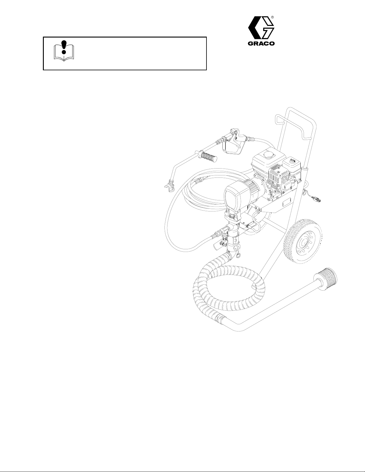
Roof Rigs
GM 1230
GASOLINE-POWERED
1200
psi (8.3 MPa, 83 bar) MAXIMUM
WORKING PRESSURE
Model 231–148
With
one gun, Heavy Duty RAC IV
DripLess T
and 861 size tip,
90 foot (28 m) hose
ip Guard,
AIRLESS SPRA
YER
First
choice when
quality counts.
Supersedes Rev. B
and PCN D
Rev. D
Model 224–483, Series A
Without
hose or gun
0394A
GRACO INC. P.O. BOX 1441
http://www.graco.com
COPYRIGHT
Graco
Inc. is registered to I.S. EN ISO 9001
MINNEAPOLIS, MN
1991, GRACO INC.
55440–1441

Table
of Contents
Warnings 3.
Setup 8
Fueling 9
Start
Flushing
Spray T
Spray Techniques 14.
Maintenance 15
Troubleshooting 16
. . . . . . . . . . . . . . . . . . . . . . . . . . . . . . . . . . . . .
. . . . . . . . . . . . . . . . . . . . . . . . . . . . . . . . . . . . . . . . .
. . . . . . . . . . . . . . . . . . . . . . . . . . . . . . . . . . . . . . .
Up
. . . . . . . . . . . . . . . . . . . . . . . . . . . . . . . . . . . . .
Guidelines
ip and T
. . . . . . . . . . . . . . . . . . . . . . . . . .
ip Guard
. . . . . . . . . . . . . . . . . . . . . .
. . . . . . . . . . . . . . . . . . . . . . . . . . . .
. . . . . . . . . . . . . . . . . . . . . . . . . . . . . . . . . .
. . . . . . . . . . . . . . . . . . . . . . . . . . . . . . .
10.
12.
13.
Service
Removing
Displacement Pump
Bearing
Drive
Pinion
Clutch 26
and Installing a Displacement Pump
. . . . . . . . . . . . . . . . . . . . . .
Housing and Connecting Rod
Housing
Housing
. . . . . . . . . . . . . . . . . . . . . . . . . . . .
. . . . . . . . . . . . . . . . . . . . . . . . . . .
. . . . . . .
. . . . . . . . . . . . . . . . . . . . . . . . . . . . . . . . . . . .
18
19.
22.
23.
24.
Engine 27
Field
Clamp 29
Clutch
Reassembly 30
Parts
Lists and Drawings
Displacement Pump
Pinion
Complete
Suction
Roofing
Drive
Accessories 38
Technical
Warranty 40
Phone
. . . . . . . . . . . . . . . . . . . . . . . . . . . . . . . . . . .
and Wiring Harness
. . . . . . . . . . . . . . . . . .
. . . . . . . . . . . . . . . . . . . . . . . . . . . . . . . . . . . .
Housing
. . . . . . . . . . . . . . . . . . . . . . . . . . .
. . . . . . . . . . . . . . . . . . . . . . . . . . . . . .
. . . . . . . . . . . . . . . . . . . . . .
Assembly
Sprayer
Kit
Pump and Pressure Control Kit
Assembly
. . . . . . . . . . . . . . . . . . . . . . . . . .
. . . . . . . . . . . . . . . . . . . . . . . .
. . . . . . . . . . . . . . . . . . . . . . . . . . . . . . .
. . . . .
. . . . . . . . . . . . . . . . . . . . . . . . . .
. . . . . . . . . . . . . . . . . . . . . . . . . . . . . . . . . .
Data
. . . . . . . . . . . . . . . . . . . . . . . . . . . . . . .
. . . . . . . . . . . . . . . . . . . . . . . . . . . . . . . . . . . . .
Number
. . . . . . . . . . . . . . . . . . . . . . . . . . . . . . .
28.
29.
32.
33.
34.
35.
35.
36.
39.
40.
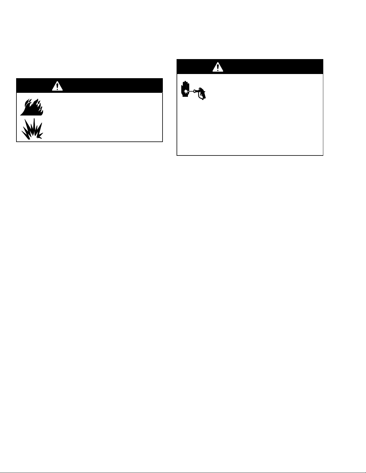
NOTE: This
sprayer in other languages. Before operating the sprayer
is an example of the English language DANGER label on your sprayer. This label is supplied with the
, apply a DANGER label in the appropriate language for
your operators, according to the separate instructions supplied with it.
FIRE
AND
EXPLOSION HAZARD
Liquids
Spray
painting, flushing or cleaning equipment with flammable liquids in
confined
Use outdoors or in extremely well ventilated areas. Ground equipment,
hoses,
A
cloths,
arcs
switches on and of
Failure to follow this warning can result in death or serious injury
areas can result in fire or explosion.
containers and objects being sprayed.
void all ignition sources such as static electricity from plastic drop
open flames
from connecting or disconnecting power cords or turning light
such as pilot lights, hot objects such as cigarettes,
f.
.
READ AND UNDERSTAND ALL LABELS AND INSTRUCTION MANUALS BEFORE USE
can be injected into the body by high pressure airless spray or
leaks
– especially hose leaks.
Keep body clear of the nozzle. Never stop leaks with any part of the
body
. Drain all pressure before removing parts.A
ing of gun by always setting safety latch when not spraying.
Never spray without a tip guard.
In case of accidental skin injection, seek immediate
“Surgical T
Failure to follow this warning can result in amputation or serious
injury.
reatment”.
SKIN INJECTION
HAZARD
void accidental trigger
-
Symbols
Warning Symbol
WARNING
This
symbol alerts you to the possibility of serious
injury or death if you do not follow the instructions.
WARNING
FIRE AND EXPLOSION HAZARD
Improper
result in a fire or explosion and serious injury
grounding, poor ventilation, open flames or sparks can cause a hazardous condition and
If there is any static sparking or you feel an electric shock while using this equipment,
ing immediately. Do not use the equipment until you identify and correct the problem.
Provide fresh air ventilation to avoid the buildup of flammable fumes from solvents or the fluid
being sprayed.
Keep the spray area free of debris, including solvent, rags, and gasoline.
Disconnect all electrical equipment in the spray area.
Caution Symbol
CAUTION
This
symbol alerts you to the possibility of damage to
equipment if you do not follow the instructions.
.
stop spray-
Extinguish all open flames or pilot lights in the spray area.
Do not smoke in the spray area.
Do not turn on or of
Do not operate a gasoline engine in the spray area.
Ground the sprayer to a true earth ground with the ground wire and clamp (supplied).
Use only electrically conductive hoses.
f any light switch in the spray area while operating or if fumes are present.
WARNING
EQUIPMENT MISUSE HAZARD
INSTRUCTIONS
Equipment
This equipment is for professional use only
Read all instruction manuals, tags, and labels before operating the equipment.
Use the equipment only for its intended purpose. If you are not sure, call your Graco distributor
Do not alter or modify this equipment. Use only genuine Graco parts.
Check equipment daily
Do not exceed the maximum working pressure of the lowest rated system component. Refer to the
T
Use fluids and solvents which are compatible with the equipment wetted parts. Refer to the
nical Data
Do not use hoses to pull equipment.
Route hoses away from traffic areas, sharp edges, moving parts, and hot surfaces. Do not expose
Graco hoses to temperatures above 82C (180F) or below –40C (–40
Do not lift pressurized equipment.
Comply with all applicable local, state, and national fire, electrical, and safety regulations.
misuse can cause the equipment to rupture or malfunction and result in serious injury
.
echnical Data
section of all equipment manuals. Read the fluid and solvent manufacturer’s warnings.
. Repair or replace worn or damaged parts immediately
on page 39 for the maximum working pressure of this equipment.
.
F).
.
.
Tech-
W
ear hearing protection when operating this equipment.
Do not use 1,1,1–trichloroethane, methylene chloride, other halogenated hydrocarbon solvents or
fluids containing such solvents in pressurized aluminum equipment. Such use could result in a
chemical reaction, with the possibility of explosion.
MOVING PARTS HAZARD
Moving
parts can pinch or amputate your fingers.
Keep clear of all moving parts when starting or operating the sprayer
Before servicing the equipment, follow the
equipment from starting unexpectedly
Pressure Relief Procedure
.
.
on page 8 to prevent the
WARNING
INJECTION HAZARD
Spray
from the gun, leaks or ruptured components can inject fluid into your body and cause extremely
serious injury, including the need for amputation. Fluid splashed in the eyes or on the skin can also
cause serious injury
Fluid injected into the skin may look like just a cut, but it is a serious injury. Get immediate medi
cal attention.
Do not point the gun at anyone or at any part of the body
Do not put your hand or fingers over the spray tip.
Do not stop or deflect leaks with your hand, body
Do not “blow back” fluid; this is not an air spray system.
Always have the tip guard and the trigger guard on the gun when spraying.
Check the gun dif
Be sure the gun trigger safety operates before spraying.
Lock the gun trigger safety when you stop spraying.
.
fuser operation weekly
.
, glove or rag.
. Refer to the gun manual.
-
Follow the
checking or servicing the equipment.
T
ighten all fluid connections before operating the equipment.
Check the hoses, tubes, and couplings daily
repair high pressure couplings; you must replace the entire hose.
Fluid hoses must have spring guards on both ends, to help protect them from rupture caused by
kinks or bends near the couplings.
Pressure Relief Procedure
on page 8 if the spray tip clogs and before cleaning,
. Replace worn or damaged parts immediately
TOXIC FLUID HAZARD
Hazardous
inhaled, or swallowed.
Know the specific hazards of the fluid you are using.
Store hazardous fluid in an approved container
state and national guidelines.
Always wear protective eyewear
solvent manufacturer
fluid or toxic fumes can cause serious injury or death if splashed in the eyes or on the skin,
. Dispose of hazardous fluid according to all local,
, gloves, clothing and respirator as recommended by the fluid and
.
. Do not

Notes
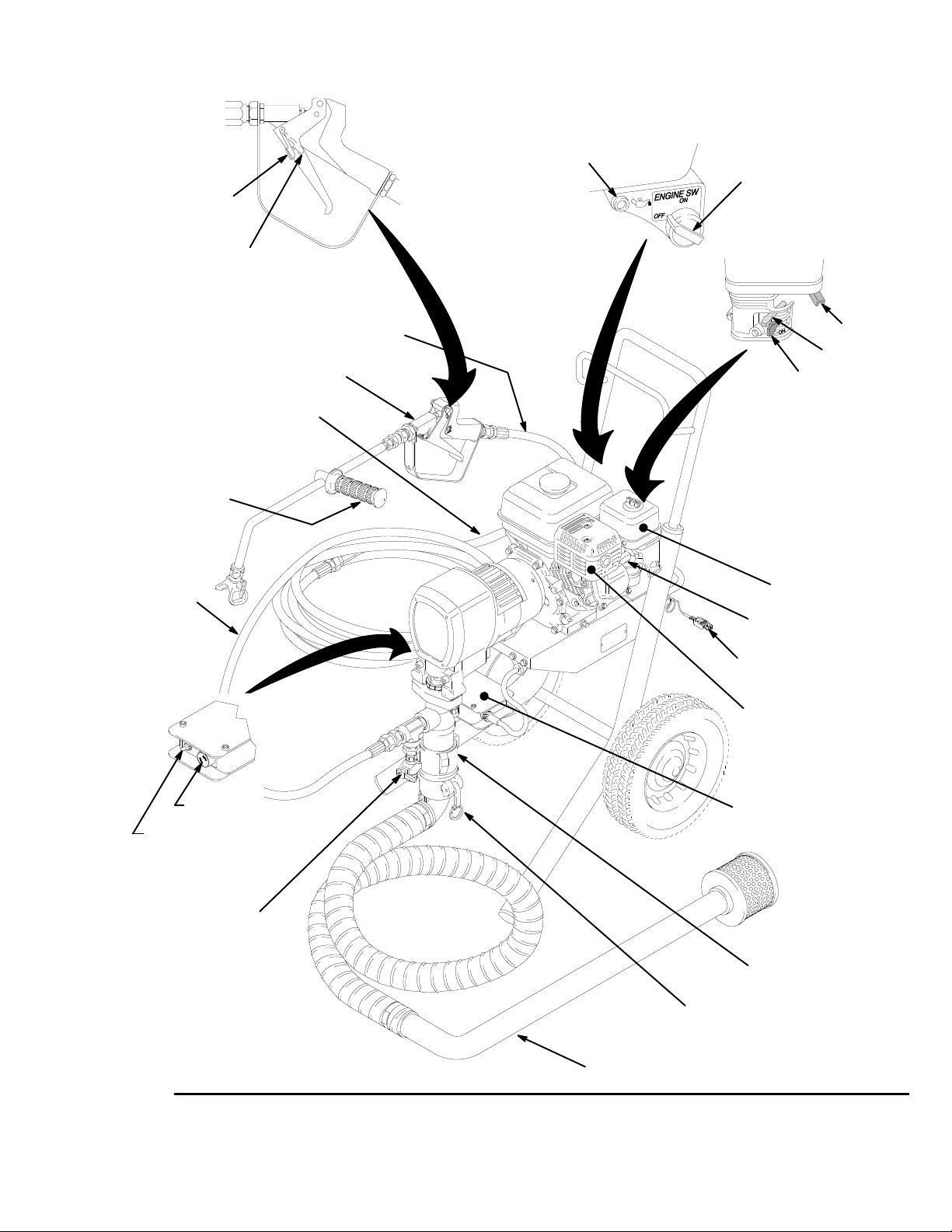
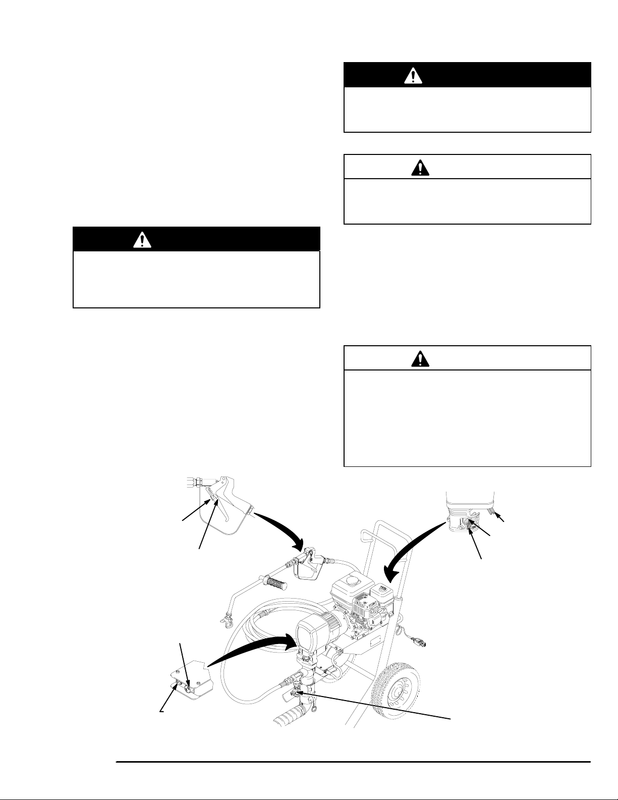
Setup
E
TRIGGER LOCK
SHOWN IN
ENGAGED OR
“SAFE” POSITION
TRIGGER LOCK
SHOWN IN
DISENGAGED OR
“OFF–SAFE” POSITION
40 ft (12 m) HOSE
WAND HANDLE
50 ft. (15 m)
MAIN HOSE
40 ft (12 m) HOSE
SPRAY GUN
ENGINE
OIL LIGHT
0015
ENGINE
ON/OFF
SWITCH
0016
FUEL
SHUTOFF
LEVER
AIR CLEANER
SP
ARK PLUG CABLE
THROTTL
CHOKE
PRESSURE
CONTROL KNOB
PRESSURE CONTROL
ON/OFF SWITCH
PRESSURE
RELIEF V
shown in closed
position
Fig.
1
0398
ALVE
SIPHON TUBE
GROUNDING CLAMP
MUFFLER
PRESSURE CONTROL
DISPLACEMENT PUMP
QUICK DISCONNECT ELBOW
0394A
Setup
General Information
NOTE:
in the text refer to the callouts in the figures and the
parts drawing.
Reference numbers and letters in parentheses
WARNING
FIRE AND EXPLOSION HAZARD
Before operating the pump, ground the
system as explained below
the section
ARD
FIRE OR EXPLOSION HAZ
on page 3.
Grounding
1.
Sprayer
cord into a properly grounded outlet. Do not use an
adapter
and be rated for 15 amps.
2.
Fluid hoses:
maximum of 150 m combined hose length to
ensure grounding continuity
Spray gun:
3.
a properly grounded fluid hose and sprayer
: plug the power supply cord, or extension
. All extension cords must have three wires
use only grounded hoses with a
.
obtain grounding through connection to
. Also read
.
Pressure Relief Procedure
WARNING
INJECTION
Fluid under high pressure can be in
jected through the skin and cause seri
ous injury
from injection, splashing fluid, or moving parts, fol
-
low the
1.
2. T
3.
4.
Pressure Relief Procedure
are instructed to relieve the pressure,
stop spraying,
check or service any of the system equipment,
or install or clean the spray tips.
Engage the gun safety latch.
urn the ON/OFF switch to OFF
Unplug the power supply cord.
Disengage the gun safety latch. Hold a metal part
of the gun firmly to the side of a grounded metal
pail, and trigger the gun to relieve pressure.
HAZARD
. T
o reduce the risk of an injury
whenever you:
.
-
-
-
4.
Object being sprayed:
5.
Fluid supply container:
6.
All solvent pails used when flushing,
local code. Use only metal pails, which are con
ductive. Do not place the pail on a non-conductive
surface, such as paper or cardboard, which inter
rupts the grounding continuity
T
o maintain grounding continuity when flushing or
7.
relieving pressure
gun firmly to the side of a grounded metal pail,
then trigger the gun.
according to local code.
according to local code.
according to
.
, always hold a metal part of the
5.
Engage the gun safety latch.
6.
Open the pressure drain valve, having a container
ready to catch the drainage. Leave the valve open
until you are ready to spray again.
-
7.
Disconnect the spark plug cable.
-
If you suspect that the spray tip or hose is completely
clogged, or that pressure has not been fully relieved
after following the steps above
tip guard retaining nut or hose end coupling and very
slowly loosen the part to relieve pressure gradually
Now clear the tip or hose.
, wrap a rag around the
.
Setup
1. Read and follow the warnings on pages 3–3
before setting up or operating this sprayer
2. Install the hoses and gun.
3. Clamp the siphon hose to the pump.
gasket
is in the quick
prevent
4. Check
gine manual, supplied. In summary: remove one oil
fill plug – the oil should be almost overflowing. See
Fig.
NANCE
Recommended
gent oil, SAE 10W–40, classified “FOR SERVICE
SE
5. Ground the sprayer before operating it. Connect
the
low the FIRE OR EXPLOSION HAZARD on page
3.
priming.
the engine oil level.
1. Add oil as necessary
section on page 15.
or SF”.
grounding clamp (32) to a true earth ground.
disconnect elbow; air leaks will
Refer to the Honda en
. Also read the MAINTE-
engine
oil: Use a high–quality
.
Be sure
, deter
the
Fol
Fueling
6. Fill the gas tank.
7. Flush the pump to remove the protective lightweight oil. See FLUSHING GUIDELINES on page
12.
8. AGITATE OR MIX THE MATERIAL THOROUGH-
Make sure the heavier material on the bottom of
LY!
-
the
container is completely mixed in.
9.
Start the sprayer. See page 10.
See FUELING, below
CAUTION
-
-
T
o avoid damaging the pressure control, follow these
precautions.
1.
Always use spray hose at least 90 ft. (27 m)
long.
2.
Do not allow water or water-base material to
freeze in the pressure control.
.
WARNING
Gasoline is extremely flammable and explosive
under certain conditions. T
or explosion:
1.
Always shut of
2.
Refuel in a well-ventilated area.
3.
Do not smoke or allow flames or sparks in the
area where the engine is refueled or where the
gasoline is stored.
4.
Do not overfill the tank. Make sure the filler cap
is securely closed after refueling.
5.
Fuel vapor or spilled fuel can ignite. If any fuel
is spilled during refueling, make sure the are is
dry before starting the engine.
1 Fuel specifications. Use automotive gasoline with
a
pump octane number of 86 or higher
knocks
fuel
2 Gasolines containing alcohol (gasohol). Do not
use
does
for
do not use the gasohol if it contains more than
5%
or pings, use a higher octane fuel.
minimizes combustion chamber deposits.
gasohol which contains methanol, if the gasohol
not contain cosolvents and corrosion inhibitors
methanol. Even if it does contain such
methanol.
f the engine before refueling.
o reduce the risk of a fire
. If the engine
Unleaded
additives,
3. General. Do not use oil and gasoline mixtures or
contaminated gasoline. Avoid getting dirt, dust or
in the fuel tank.
water
4. Tank
5. Shut off the engine switch before refueling.
6. After refueling, tighten the fuel tank cap firmly.
capacity:
(13
mm) at the top of the tank for gas expansion.
0.95 gallons (3.6 liter).
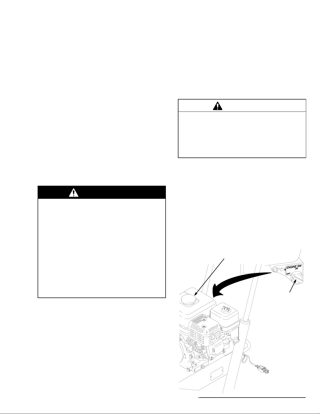
FILL
CAP
Leave 1/2 in.
ENGINE
ON/OFF
SWITCH
NOTE: The HONDA engine warranty does not cover
damage
taining
for
resulting from the use of gasolines con
alcohol.
more information.
See the HONDA engine manual
-
Fig.
2
0015
0141D
Start
Before You Start The Sprayer
1 See FLUSHING GUIDELINES, page 12, to deter-
mine
if the unit should be flushed.
2 Be sure the gas tank is full.
3 Check the engine oil level.
NOTE: The
4 Push the spark plug cable firmly onto the spark
plug.
5 If
Refer
engine stops automatically
if
it is low on oil. If you try to start it again without
adding
more oil,
switch
glows as you pull the starter rope.
a red light near the engine on/of
the sprayer in not primed, remove
to Fig. 3 as you start the sprayer
, or will not start,
the spray tip.
.
Up
3. T
urn OFF the pressure control switch.
4. To start the engine:
a. Turn the pressure adjusting knob all the way
counterclockwise
b. Slide the metal throttle lever away from the fuel
tank
c. If
f
the engine is cold, close the
the
the engine is warm, close the
If
the
d. T
urn ON the engine switch.
to the lowest pressure setting.
to the maximum position (fully left).
choke by moving
gray lever
.
choke by moving
gray lever only half way or not at all.
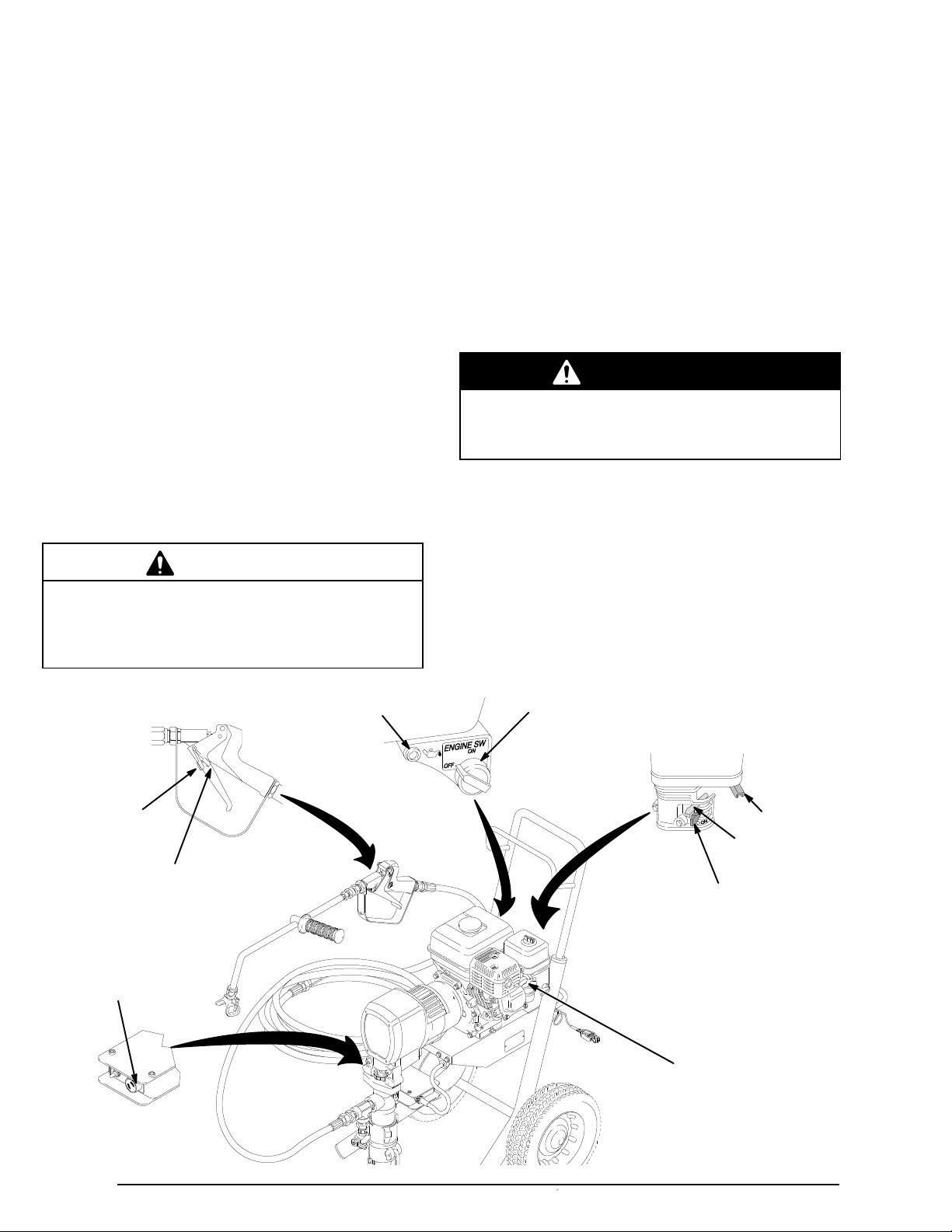
WARNING
Start Up
1. Place the siphon tube into the coating, water or
solvent container, depending on whether you are
flushing
or are ready to spray
.
2. Open the black fuel shutoff lever by pushing it in
direction of the arrow
the
.
CAUTION
Never start the engine unless fluid pressure is re
lieved and the pressure control switch is turned OFF
Attempting to start the engine when it is pressurized
could damage the recoil system.
ENGINE
OIL LIGHT
TRIGGER LOCK
shown in
engaged or
“safe” position
TRIGGER LOCK
shown in
disengaged or
“off–safe” position
.
A starter rope that recoils too quickly may hit
someone and cause serious injury
also jam in the recoil assembly
e. Hold
f. Open
the frame of the sprayer with one hand
pull
the starter rope rapidly
holding
turn
the rope as you let it return.
the rope until the engine starts.
the choke as soon as the engine starts, ex
. The rope could
.
and firmly
cept in cold weather. In cold weather, leave the
choke
5. Engage
gun
0015
closed for 10 to 30
it to keep the engine running.
ing
the gun trigger safety latch
forward.
ENGINE
ON/OFF
SWITCH
seconds before open
0016
FUEL SHUT
LEVER
shown in off position
and
. Continue
Pull and re
by tipping the
THROTTLE
CHOKE
shown in
choked position
OFF
-
-
-
PRESSURE
CONTROL KNOB
Fig.
3
0398
SP
ARK PLUG CABLE
0394A
6. To start the pump:
a. Place
b. Reduce the engine speed by moving the metal
c. T
d. T
e. Turn the pressure control knob 1/4 turn from
f.
a container under the pressure drain valve
and
open the valve.
throttle lever away from the fuel tank about half
way
to the left.
urn the pressure control knob to minimum.
urn ON the pressure control switch.
minimum pressure. Run the pump until fluid
flows
smoothly from the pressure drain valve.
Close the pressure drain valve.
Start
Up
WARNING
T
o reduce the risk of serious injury from fluid injec
tion, never operate the spray gun with the tip guard
removed.
8. Install the tip guard and spray tip.
CAUTION
Use the lowest fluid pressure and the lowest throttle
setting needed. Higher settings cause excessive
clutch cycling and premature tip and pump wear
See page 13.
-
.
WARNING
Hold the handle of the wand firmly when triggering
the gun to reduce the risk of it kicking back from
the surge of pressure, which could cause serious
injury.
g. Disengage the gun safety latch. Hold a metal
part of the gun firmly against a grounded metal
container. Holding the gun firmly with both
hands,
squeeze the trigger until
the gun.
h.
Release the trigger
7. If you have not primed the unit with the coating
yet, move the siphon tube to the coating container.
Release
the water/solvent pail just until coating appears. Tip
the gun forward and fully release the trigger to engage
the trigger safety
the trigger safety latch.
TRIGGER LOCK
shown in
engaged or
“safe” position
TRIGGER LOCK
disengaged or
“off–safe” position
. Engage the safety latch.
latch. T
shown in
fluid flows from
rigger the gun into
9. Adjust
fore transporting the hoses to the roof. Trigger
the
and atomization. Turn the pressure adjusting knob
until you get a good pattern. Then slowly lower the
throttle
spray
10.
Read SPRA
the engine speed and pump pressure be
gun onto a test paper to check the spray pattern
setting as far as
pattern (the clutch does not cycle).
Y TECHNIQUES on page 14.
you can without changing the
CAUTION
Close the black fuel shutof
transporting the sprayer to prevent fuel from flooding
the engine.
Keep the sprayer upright and level when operating it
and when transporting it. This prevents crankcase oil
from leaking into the combustion chamber
makes start up very dif
f lever whenever you are
, which
ficult.
0016
THROTTLE
CHOKE
choked position
FUEL SHUT
LEVER
shown in off position
shown in
OFF
-
Fig.
PRESSURE
CONTROL KNOB
4
0398
PRESSURE CONTROL
ON/OFF SWITCH
PRESSURE DRAIN V
ALVE
0394A
Flushing
Guidelines
WARNING
To
reduce the risk of serious injury
injection, always follow the
dure W
ing, cleaning, or shutting down the sprayer
arning
on page 8 before checking, adjust
Pressure Relief Proce
When To Flush
1. Flush
2. Changing coatings.
3. Changing from water–base to oil–base coating.
4. Changing from oil–base to water–base coating.
a new sprayer
Before using water–base coating, flush with a compatible solvent, then warm, soapy water, and then
water
clean
Before using oil–base coating,
ible
solvent.
Flush
solvent.
Flush with a compatible solvent, then warm, soapy
water,
.
with warm, soapy water
and then clean water
to remove the protective oil.
Use a compatible solvent.
, including fluid
.
flush with a compat-
, and then a
.
compatible
-
-
2. Put
3. Start the sprayer. Trigger the gun into the coating
4. Move the gun to the grounded flushing container.
5. Check all fluid connections for leaks. Relieve pres-
6. Remove
the siphon tube in a grounded metal pail of water
or
compatible solvent.
just
container
nozzle.
Trigger the gun until clean water or solvent comes
from the it. See Fig. 6. Release the trigger and en-
the safety latch. Open the drain valve to clean
gage
it.
sure before tightening any connections. Start the
sprayer.
gage the gun safety latch. Trigger the gun to force
or solvent from the hose. Do not let the pump
water
run
dry for more than 30 seconds to avoid damaging
the
pump packings! Relieve pressure.
until water or solvent comes from the
Release the trigger
Recheck the connections for leaks.
the siphon tube from the solvent pail.
.
Disen
-
5. Storage.
Flush the pump only with a compatible solvent, fol-
lowed
by an oil–base solvent, such as mineral spirits.
Leave the drain valve open!
6.
Startup after storage.
Before
using water–base coating, flush out the com
solvent with warm, soapy water, and then with
patible
clean
water
.
using oil–based coating, flush out the compat
When
solvent with the coating to be sprayed.
ible
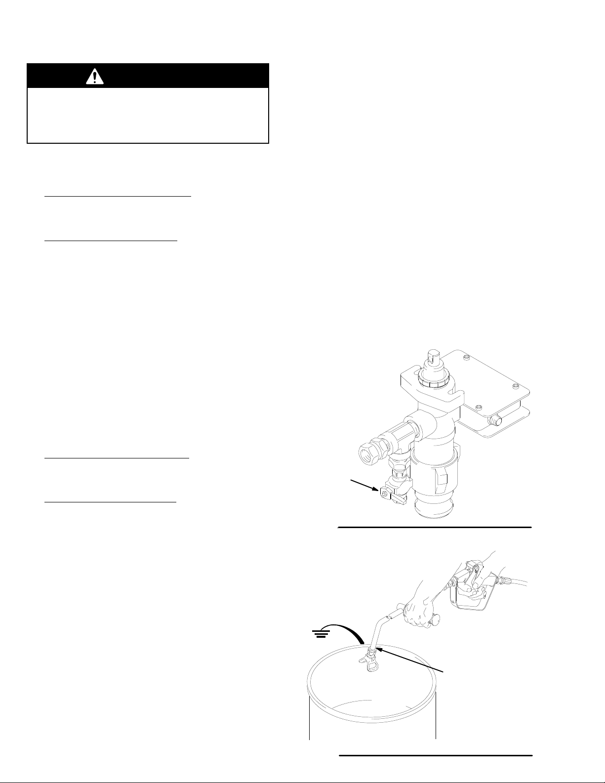
How To Flush The Pump Only
1. Relieve pressure. Leave the drain valve open. See
5.
Fig.
2.
Disconnect the siphon assembly
3. Put the pump in a grounded metal pail of water or
compatible
4. Start the sprayer – see page 10. Flush until the ball
in the foot valve is clean and moves up and down
easily.
solvent.
.
How To Flush The Entire Fluid System
-
-
PRESSURE
DRAIN VALVE
shown in closed
position
Fig.
5
0553
Maintain
metal-to-metal
when
reduce the chance of
static sparking and
splashing.
firm
flushing to
contact
1. Relieve pressure. Leave the drain valve open. See
Fig.
5.
Fig.
6
0406

Spray
T
ip and T
WARNING
To
reduce the risk of fluid injection or splashing in
the eyes or on the skin, completely relieve the fluid
pressure before installing, cleaning, or changing
tips. See the
8.
Pressure Relief Procedure
on page
ip Guard
RETAINING
Fig.
7
NUT
HOUSING
0464
Installation
1. Insert
2. Install the metal seal in the housing, flat side first.
3. Install
4. Snap
the housing through the back
nut
and pull it forward. See Fig. 7.
Fig. 8.
See
the cylinder tip in the housing so its small ori
faces front. See Fig. 9.
fice
on
the tip guard. Install the screw and the white
gasket.
See Fig. 10.
of the retaining
Operation
Be
sure the tip arrow handle is in the FULL SPRA
tion
before operating the gun. See Fig. 10.
Y posi
WARNING
Keep clear of the nozzle. High pressure fluid from
leaks or spray can penetrate the skin and cause
extremely serious injury
amputation. The tip guard provides extra protection
against injection, but does not prevent it. Never cut
of
f the tip guard.
, including the need for
-
-
RETAINING
HOUSING
SEAL
Fig.
8
HOUSING
CYLINDER
SMALL ORIFICE
Fig.
9
SCREW
TIP GUARD
Fig.
10
NUT
0465
TIP
0466
GASKET
0467
Clearing a clogged spray tip See
Engage the trigger safety latch.
1.
2. Turn
3. Disengage
4. Engage the trigger safety latch. Return the arrow
the arrow handle to the FULL CLEAN position.
the
trigger safety latch and trigger the gun
into
the waste container
handle
to the FULL SPRA
.
Y position.
Fig. 1
1.
Maintenance
Replace
these
the gasket and seal
parts wear at about the same rate.
whenever you replace a tip;
GUN NOZZLE
RAC IV
DripLess
TIP GUARD
FULL SPRA
Fig. 11
SwitchTip
HANDLE
Y POSITION
FULL
CLEAN POSITION
0093

Spray
T
echniques
MOVE HORIZONT
A
T A STEADY RA
Fig. 12
Type of Coating
Primers N/A
Aluminum Solvent–Base
Aluminum Emulsion
Asphalt Solvent–Base
Asphalt Emulsion
Aluminum Solvent–Base
Aluminum Emulsion
Asphalt Emulsion
1
Roof coatings vary greatly. The formulas, batch,
temperature,
cosity. If the sprayer does not atomize the coating
well, thinning and/or agitating it should help. Apply
thinned
thickness.
should
2
A 0.061 tip is standard with the sprayer
coating more heavily to get an equal dry film
be applied about 10% thicker
ALLY
TE
1
and age of the coating all af
For example, coating that is thinned 10%
Fibered? Recommended
No
No
No 0.051
No 0.051
Yes 0.061
Yes 0.061
Yes 0.061
Tip Size
0.031 or larger
0.041 or larger
0.051 or larger
2
fect its vis
.
.
HOLD THE GUN PERPENDICULAR T
AND 24” (610 MM) ABOVE THE SURF
OVERLAP
the spray stroke 24” (610
Start
and pull the trigger
face
the gun is still moving, and as you approach the other
edge, release the trigger. This method avoids excess
material
Do not try to increase coverage by increasing the fluid
pressure!
necessary
the life of your sprayer and minimizes coating lost by
overspray.
there
If
minimize
build-up at the end of each stroke.
Use a slower
to get the results you want; this helps prolong
is a wind, angle the spray pattern into the wind to
drifting.
EACH STROKE BY 50%
mm) above the target sur
as the
gun is moving.
stroke. Use the lowest pressure
The best way to control the rate of coverage is with the
tip size.
gun
er tip orifice applies more coating. The width of the pat-
depends on the fan pattern of the tip you choose.
tern
A small tip orifice applies less coating. A larg
O
ACE
0551
-
Then, while
-

Maintenance
WARNING
T
o reduce the risk of serious injury
the
Pressure Relief Procedure
checking, adjusting, cleaning, or shutting down the
sprayer.
, always follow
on page 8 before
CAUTION
For detailed engine maintenance and specifications,
refer to the HONDA engine manual.
CAUTION
Close the black fuel shutof
transporting the sprayer to prevent fuel from flooding
the engine.
Keep the sprayer upright and level when operating it
and when transporting it. This prevents crankcase oil
from leaking into the combustion chamber
makes startup very dif
f lever whenever you are
, which
ficult.
DAILY: Check
DAILY: Check
AFTER THE FIRST 20 HOURS OF OPERATION AND
100 HOURS THEREAFTER:
EACH
WEEKLY: Remove
ment. In very dusty environments, check the filter daily.
Replace
can
SP
plug.
Always
the element as needed. Replacement elements
be purchased from your local HONDA dealer
ARK PLUG:
Gap the plug to 0.025 to 0.030 in. (0.7 to 0.8
use a spark plug wrench.
the engine oil level and
and fill the gas tank.
the air filter cover and clean the ele
Use only a (NGK)
fill as necessary
Change the oil.
BP6ES or BPR6ES
.
mm).
.
-

Troubleshooting
WARNING
Check everything in the guide before disassembling
the sprayer
.
T
o reduce the risk of serious injury whenever you
are instructed to relieve pressure, always follow the
Pressure Relief Procedure
PROBLEM CAUSE SOLUTION
Engine/sprayer won’t start
Engine won’t “fire” or
“pull over”
Engine operates, but
displacement pump doesn’t
Also see manual 308–126.
on page 8.
Engine switch not on
Out of gas
Engine oil level low
Spark plug cable disconnected or
spark plug damaged
Adjusting the pressure control knob
doesn’t
Oil seepage into combustion
chamber
Pressure control switch turned OFFTurn on pressure control switch.
Pressure setting too low
T
start pump
ip clogged
Relieve the pressure before disassembling the spray
er.
T
urn on engine switch.
Refill gas tank.
Try
starting engine. If light on
glows,
replenish oil.
Connect cable on top of engine or replace
spark
plug.
Return pressure control to authorized Graco dealer for repair.
Remove
times. Clean and replace plug. Try to start.
Keep
Increase pressure.
Clean tip.
spark plug. Pull starter rope 3 or 4
sprayer upright to avoid oil seepage.
-
rear of engine
Displacement pump rod seized by
dry coating
Connecting rod worn or damaged
Drive housing worn or damaged
Electrical power not energizing field
Clutch worn or damaged
Pinion assembly worn or damaged
Service pump. See page 19.
Replace connecting rod. See page 22.
Replace drive housing. See page 23.
Check wiring connections. See page 28.
With pressure control switch ON and pressure
turned to MAXIMUM, use a test light
check continuity across black and white
wires
from pressure control.
Have pressure control checked by authorized
Graco dealer
Service clutch. See page 26.
Service pinion assembly
.
. See page 24.
to

PROBLEM CAUSE SOLUTION
Engine starts but dies
Displacement
on
upstroke
Displacement
on
downstroke or both strokes
Coating leaks into wet–cup
Low fluid delivery
pump output low
pump output low
Oil level drops below oil sensor
Siphon hose strainer is clogged
Piston ball check not seating
Piston packings worn or damaged
Sleeve o–ring in displacement pump
worn or damaged
Siphon hose strainer is clogged
Piston packings worn or damaged
Intake valve ball check not seating
properly
Clutch
worn or damaged
Loose wet–cup
Throat packings worn or damaged
Displacement rod worn or damaged
Siphon hose strainer is clogged.
Add oil.
Clean strainer
Service piston ball check. See page 19.
Replace packings. See page 19.
Replace o–ring gasket. See page 19.
Clean strainer
Replace packings. See page 19.
Clean and service intake valve. See page
19.
Replace clutch. See page 26.
T
ighten wet–cup just enough to stop
leakage.
Replace packings. See page 19.
Replace displacement rod. See page 19.
Clean strainer
.
.
.
Pressure setting too low
Engine RPM too low
Large pressure drop in hose
Spitting from gun Air in fluid pump or hose
Fluid supply is low or empty
Increase pressure. See
Step 9, page 1
Increase throttle setting. See
Steps 4b and 9, pages 10 and 1
Use larger diameter hose.
Change
nect coupling, if worn or missing. Replace
pump cylinder o–ring. Then prime the
pump.
See
Refill and prime the pump. See Startup,
page
10. Check fluid supply often to prevent
running
the pump dry
1.
gasket in siphon hose quick discon
Startup
Startup,
Startup,
1.
, page 10.
.
-

Removing
and I
nstallin
g a D
isplacemen
t P
ump
Removal
WARNING
To
reduce the risk of serious injury
the
Pressure Relief Procedure
repairing the sprayer
1. Flush
the sprayer
.
. Remove the suction
, always follow
on page 8 before
hose, if used.
WARNING
To
reduce the risk of pinching or amputating a
finger
, keep your fingers away from the area of the
connection rod and pin while jogging the engine.
2.
Start the engine. Jog the pressure control ON/OFF
switch
until the connecting link stops near the bottom
of
the stroke and is fully exposed. See Fig. 13. Shut
off
the engine.
3. Unscrew
plug
4. Relieve
5. Remove the outlet hose. Slightly loosen the two
mounting
6. Use a small screwdriver to push in the connecting
link
up from the back of the connecting link. Then push
the
the collar
the cord from the pressure control. See Fig. 14.
the pressure
screws. See Fig. 13.
pin just until you can gently pry the retaining ring
pin in so it falls out the back.
of the power supply cord and un
.
7. Remove the two mounting screws while supporting
weight of the pump with your free hand.
the
Installation
1. Push
2. Pull the displacement rod out of the pump 2 to 3 in.
3. Align the flats of the pump piston rod and the pump
the pin just barely into the connecting link, but
not
into the mating hole of the displacement pump.
(50–75 mm).
outlet.
Lift the pump into position and gently push on
the pin while moving the pump slightly until the pin
slips into the hole. Be sure the retaining ring snaps
over the end of the pin.
down
WARNING
Be sure the retaining spring is firmly in the groove
of the connecting link, all the way around, to pre
vent it from working loose due to vibration. See Fig.
-
13.
If the pin work loose, it or other parts could break
of
f due to the force of the pumping action and
result in serious injury or property damage, includ
ing damage to the pump, connecting link or bearing
housing.
Procedure continued on page 19.
-
-
Fig.
13
FRONT VIEW OF PUMP AND
SPRA
YER CONNECTING LINK
PIN
BEARING HOUSING
RETAINING RING
CONNECTING LINK
MOUNTING SCREWS
T
orque to
20 ft–lb (27 N.m)
CUTAWA
SHOWS HOW PIN GOES
THROUGH CONNECTING ROD
PIN
PUMP PIST
CONNECTING LINK
RETAINING RING
ON ROD
Y VIEW
BACK
OF PUMP
FRONT OF PUMP
0407

Removing
and I
nstallin
g A D
isplacemen
t P
ump
4. Check
5. Lift
6. Plug
the back of the bearing housing to be sure the
parts
are installed properly
the pump to align the mounting holes and install
the mounting screws. IMPORTANT – torque the
screws
the
Fig. 14.
to 20 ft-lb (27 N.m). See Fig. 13.
in the power cord so the notch in the collar and
tab in the socket align. Screw on the collar
.
Displacement
WARNING
To
reduce the risk of serious injury
the
Pressure Relief Procedure
repairing the sprayer
.
, always follow
on page 8 before
. See
Fig.
14
Pump
423
401
420
PRESSURE CONTROL
TAB
NOTCH
COLLAR
0408
416
414
415*
406*
Disassemble the pump
1
See page 18 for how to remove the pump.
2 Use a hard rubber mallet on the tabs of the lug nut
to loosen the foot valve housing.
(421)
3
Disassemble the pump, but do not disassemble the
piston
rod (401) from the piston housing (416)
one
of those needs to be replaced. Due to the highstrength
the joint must be heated before disassembly. Refer
to
Clean and inspect all parts
1 Use a compatible solvent to thoroughly clean all
parts
2. Inspect the parts, including seats, for nicks and
scratches. Replace worn or damaged parts as they
cause the packings to wear more quickly and/or result
Loctite used at the joint of these two parts,
Fig. 15.
and remove all traces of sealant.
in poor pump performance.
unless
*419
*403
417
*404
*405
*404
*407
418**402
413*
412*
408*
422
410
411*
409
421
Continued on page 20.
Fig. 15
0412

Displacement
2
Pump
Repair
1A
2 Parts
Reassemble the pump
NOTE: Refer to Fig. 13 for reassembly except where
NOTE: Grease
1. Install the ball guide (409), ball (411*) and intake
2.
3. On the piston seat (422), install the u–cup seal
4. Install the nut (414) on the piston seat (422). Hand
NOTE: If
Kit
Packing Repair Kit, Part No. 224–523, is
Use
all the parts in the kit for the best results.
included in the kit are marked with an asterisk
in
the text and drawings. For example, 408*.
noted.
all packings and o–rings before installing
them.
housing
Place new o–rings (404*) on the cylinder (405).
(408*), lips down. Install the female gland (412*).
With
install
stall
tighten
(410) in the lug nut (421).
the lips of the v–packings facing up, alternately
the leather (407*)
the male gland (406*).
the nut very firmly
you disassembled the piston rod
ton
housing (416), clean the threads
Apply red Loctite and torque to 35–50 ft–lb
(47–68
N.m).
and poly packings (413*). In
.
available.
(401) and pis
thoroughly
7. From the top of the pump housing (417), install the
gland (403). With the lips of the v–packings
male
ing down, alternately install the leather packings
(418*), and poly packings (402*). Install the female
(419*).
gland
8. Screw
9. Grease the o–rings on the cylinder (405). Slide the
10. Grease the piston rod (401) and piston packings.
11. Align the holes in the top of the piston rod with the
NOTE: If
-
12.
13. Install
.
in the packing nut (420) loosely
after the pump is installed and operating.
ened
cylinder
Slide
cylinder so it extends out of the piston housing 2–3
in.
ings.
pump
Install the intake valve housing and tighten firmly
(20)
into the bottom of the pump housing (417).
the piston rod assembly into the bottom of the
(50–75 mm). Be careful not to damage any pack
outlet.
you push the piston rod too far out of the pump
housing, using a hard rubber mallet (ONLY!) to
tap
it down.
If
the piston rod does not extend out far enough,
remove
and tighten it just enough to prevent leakage.
the foot valve and tap the piston up.
the pump and prime
it. Check the packing nut
. It will be
fac
tight
.
-
-
-
5. Apply
Loctite green (supplied in the repair kit) to the
piston
seat (422) threads. Install the ball (415*).
CAUTION
Before assembling the piston, not that the top of the
piston seat (422) has four flutes (B) and that the
piston housing (416) has four holes (A). T
these flutes and holes provide the fluid flow path.
Failure to align the parts properly
Step 6, will result in poor pump performance.
6. Back off the piston housing just until the holes and
flutes (B) mentioned in the CAUTION are perfectly
aligned,
through
ton housing (416) down to the nut (414) and torque
to
and the tips
the holes (A). See Fig 20–1. Screw the pis
90–125 ft–lb (122–170 N.m).
(B) are not visible when you look
, as instructed in
ogether
416
HOLE
FLUTE
TIP
-
Fig. 16
422
055

Displacement
Pump
20
V–P
ACKINGS MUST
FACE DOWN
LEATHER
LIPS OF
V–PACKINGS
F
ACE UP
U–CUP
LIPS MUST
FACE DOWN
LIPS
*
4
5
*15
*13
MUST
*12
*
8
SEAL
*
2
POLY
OF
19*
18*
LEATHER
LIPS OF V–P
MUST F
ACE DOWN
3*
1
16
14
6*
7*
POLY
LIPS
OF V–P
MUST F
ACE UP
21
4*
ACKINGS
T
ORQUE ROD (1) T
HOUSING (16) T
34–50 FT–LB
(44–68 N.m)
TORQUE
T
T
(150 N.m)
NUT (14)
O HOUSING (16)
O 1
10 FT–LB
ACKINGS
O
O
Fig.
17
10
0411

Bearing
Housing and Connecting Rod
WARNING
To
reduce the risk of serious injury
the
Pressure Relief Procedure
repairing the sprayer
.
, always follow
on page 8 before
9. Install the screws (48) and lockwashers (49) on the
bearing housing. Tighten the screws evenly to
ft–lb (34 N.m).
25
10.
Refer to
Installing the pump
on page 18.
NOTE:
1.
2. Remove
3. While
4. Inspect
5. Evenly
6. Assemble
7. Clean the mating surfaces of the bearing (23) and
Steps 1 to 10 refer to Fig. 18.
Refer to
the
one hand, lightly tap the lower rear of the bearing
housing
drive
connecting
the
in
necting rod link (D), with high–quality motor oil (do
not
in the connecting rod assembly (22) with bearing
grease
ing (23).
drive
Removing the pump
the screws
bearing housing (23).
pulling the
(23)
with a plastic mallet to loosen it from the
housing (20). Pull the bearing housing and the
rod assembly of
the crank (A) for excessive
drive housing. See page 23.
lubricate the inside of the bronze bearing
the bearing housing (23), and the inside of the con
use grease). Liberally pack the
(20d), supplied.
the connecting rod (22)
(20) housings.
(48) and lockwashers (49) from
connecting rod assembly (22) with
on page 18.
f the drive housing.
wear and replace
(C)
roller bearing (E)
and bearing hous
20
A
E
49
D
22
23
B
C
TORQUE TO
25 ft–lb
(34 N.m)
48
-
-
8. Align
the connecting rod with the crank (A) and care
fully align the locating pins (B) in the drive housing
with the holes in the bearing housing (23). Push
(20)
the bearing housing onto the drive housing or tap it
place with a plastic mallet.
into
CAUTION
DO
NOT use the bearing housing screws (48) to align
or seat it with the drive housing. These parts must be
aligned
ture
using the locating pins (B), to help avoid
bearing wear
.
prema
-
-
Fig.
18
0400

Drive
Housing
WARNING
To
reduce the risk of serious injury
the
Pressure Relief Procedure
repairing the sprayer
NOTE:
1. Disconnect the suction hose (A). Disconnect the
2. Disconnect
3. Remove the four screws (48) and lockwashers (49)
4. Lightly
5. Remove the bearing housing screws (41) and the
6. Lightly
Refer to Fig. 19 for this procedure.
pressure control cord (62). Remove the front cover
(21).
the pump outlet hose.
the bearing housing (23).
from
tap the back of the bearing
a plastic mallet. Pull the pump, bearing housing and
connecting
one
assembly
pinion
tic
mallet to loosen it from the pinion housing (19p).
rod away from the drive housing (20)
housing screws (3).
tap around the drive housing (20) with a plas
.
.
, always follow
on page 8 before
housing (23) with
as
20
CAUTION
Do not drop the gear cluster (1) when removing the
drive
housing (20). The
The
gear may
or
the pinion housing.
Do not lose the thrust balls (20c and 19k) located at
each
end of the gear cluster
ly covered with grease, usually stay in the shaft recesses,
between the gears and not
ously
damage
place, the bearings will wear prematurely
7. Liberally
gear cluster (1). Be sure the thrust balls (20c and
19k)
8. Place
silver–colored washer (20b) on the shaft protruding
from
the gears and push the new drive housing straight
onto
-
9. Reassemble the sprayer. Or, go to the next section
in
this manual if further service is needed.
B
20b
20a
stay engaged in either the drive housing
but they could be dislodged. If they are caught
the drive housing. If the balls are not in
apply bearing grease (20d,
are in place.
the bronze colored washer (20a)
the big bearing of the drive housing (20). Align
the pinion housing and locating pins (B).
gear cluster is easily damaged.
. The balls, which are
removed, the balls will seri
supplied) to the
heavi
.
and then the
-
-
TORQUE TO
40
21
48
25 ft–lb
(34 N.m)
49
23
41
2
62
20c
19p
3
2
19k
1
Fig.
19
A
0401

Pinion,
Disassembling these parts can start from the pinion
housing
or from the clutch, if no pinion service is
Clutch, Clamp, Field, and Engine
needed.
If starting from the pinion housing
1
to 6 of
ue
If starting from the clutch
DRIVE HOUSING
with the procedure below
, on page 23, and then contin
.
, see page .
, first follow Steps
Pinion
Removing the Pinion Housing
WARNING
To
reduce the risk of serious injury
the
Pressure Relief Procedure
repairing the sprayer
NOTE:
1 Remove
2 Pull the pinion housing (19p) away from the clutch
Refer to Fig. 20 for Steps 1 to 3.
the two bottom screws (3) first, and then re
the top three screws (3).
move
housing
(17). The armature (9b) will come with it.
.
, always follow
on page 8 before
-
Housing
-
3 Pull
Do
on
NOTE: To
the armature (9b) of
of
the pinion housing.
not lose the thrust ball (19k). Refer to the CAUTION
page 23 for more information.
disassemble the pinion, go to
Pinion, page 25. To disassemble more of the
sprayer,
er from this point, go to Reassembly, page 31,
7.
Step
f the hub (19j –
CAUTION
go to page 27. T
see Fig.
Repairing the
o reassemble the spray
21)
-
19p
19k
Fig.
20
3
2
17
9b
3
2
SEE PAGE 26 FOR PINION
0171

Pinion
Housing
CUTAWA
PINION HOUSING (19a)
Fig.
Y VIEW OF
0041
Lubricate exterior
21
Repairing the Pinion
NOTE: Refer
NOTE: A
to Fig. 21 except where noted.
hydraulic press is required
pinion parts individually.Otherwise, use Repair
Kit No. 221–032, which includes the shaft and
bearings
pre–assembled and lubricated.
BACK OF PINION HOUSING (19a)
PRESS PINION ASSEMBL
IN HERE
19a
Y
19b
19c
19d
19c
Lubricate exterior
if you purchase the
19k
19m**
19j**
19h**
Lubricate inner and
outer diameters
19g**
Lubricate teeth
19f**
Lubricate
outer diameters
**Included in Repair Kit 221–032
inner and
0169
If purchasing parts separately, use these instructions.
Disassemble as far as needed for the parts being
replaced.
NOTE: The
old
bearings (19h and 19f) will be damaged
when
removed.
need
to remove them for any reason.
Have extra ones on hand if you
If using Repair Kit 221–032, follow Steps 1 to 5, below
1. Remove
the small ring (19m**) from the hub (19j) and
the large ring (19k) from the bearing recess of the
pinion
housing (19a).
2. Push on the front of the shaft (19g**) to force the
bearing
and hub assembly out of the housing (19a).
3. Install the new shaft assembly into the pinion housing,
pushing it to the shoulder of the housing (19a).
4.
Install the rings (19k and 19m**).
5. Go
to
Reassembly
page
26.
PLACEMENT OF STEEL BLOCKS WHEN
PRESSING OFF LARGE BEARING (19h)
ROUND STEEL
BAR T
O PUSH
ON SHAFT
(19g)
LARGE
BEARING
(19h)
, page 31, Step 7, or continue on
HYDRAULIC
PRESS
HUB (19J)
STEEL BAR
STOCK
TWO STEEL
BLOCKS
(only one shown)
.
1.
Remove the small ring (19m) from the hub (19j).
2. Remove
of
3. Push
ing
4.
Using a hydraulic press,
stock
the snap ring (19k) from the bearing recess
the pinion housing (19a).
on the front of the shaft (19g) to force the bear
(19h) and hub (19j) assembly out of the housing.
place pieces of steel bar
on the inner race of the large bearing (19h) and
press the shaft through the hub and bearing. Then
turn over the shaft and press out the small bearing
(19f).
See Fig. 22.
5.
Apply lubricant to the parts as shown in Fig. 21.
6. Press fit the following parts: Large bearing (19h) to
the
large shoulder of the shaft (19g).
Small
(19f) to the shoulder of the shaft (19g). Hub (19j)
onto the shaft (19g) all the way to the large bearing
(19h).
7. Install
the shaft assembly
of
the housing (19a).
, pushing it
to the shoulder
8. Install the snap ring (19k). Install the small ring
(19m).
-
bearing
Fig.
22
PRESS PLA
TFORM
0043
9. Go
page
to
Reassembly
26.
, page 31, Step 7, or continue on

Clutch
NOTE: The clutch assembly (9) includes the armature
and rotor (9a). The armature and rotor must
(9b)
be
replaced together so they wear evenly
.
NOTE: If the pinion assembly (19) is not yet separated
from the clutch housing, follow Steps 1 to 4.
Otherwise,
1.
Relieve the pressure.
start at Step 5.
2. Disconnect the hose from the displacement pump.
Disconnect the cord set (62) from the pressure
control.
3. Remove the bottom two screws (3) from the clutch
housing (17) and then remove the remaining three
screws (3).
4. Tap lightly on the back of the bearing housing (23)
with
a plastic
mallet to loosen the assembly (D) from
the clutch housing (17). Pull the assembly away; the
armature
(9b) will come with it.
5.
Remove the armature from the pinion.
6.
There are two ways to remove the rotor (9a):
a. Remove
Install
the
the
the capscrews (4) and lockwashers (2).
two of the screws in the threaded holes in
rotor (9a). Alternately tighten the screws until
rotor comes of
f. See Fig. 23.
b. Use a standard steering wheel puller (A) with two
1/4–28
short
x 3 or 4 in. long screws (B). Replace
screws of the steering wheel puller with the
longer screws. Turn the screws (B) into the
threaded
holes of the
rotor (9a). T
ighten the cap
screw (C) of the tool until the rotor comes off.
Detail in Fig. 23.
See
7. Skip
ahead to
tinue
on page 27.
Reassembly, page 31, Step 6, or con
the
-
-
Fig. 23
TORQUE TO 7 ft–lb (9.5 N.m)
19
23
D
9b
3
2
17
9a
2
4
3
2
THREADED
HOLES
PINION SHAFT
INSIDE THIS
HOUSING
A
B
C
62
USE A STEERING WHEEL
PULLER T
O REMOVE ROT
OR
Ref
9a
0402

Engine
1 Working
move
See
under the mounting plate
(A) of the cart, re
the screw (5), lockwasher (6) and washer (7).
Fig. 24.
2 Remove the engine-mounting locknuts (43) and
screws
(42). Disconnect
the mating black, white and
green wires. Pull the wires carefully through the
grommets
(8) before removing the engine. See Fig.
24 and 25.
3 Lift
4 Remove
5Go
the
engine carefully and place it on a work bench.
the
Field
and W
Clutch
Housing
to
Reassembly, page 30, Step 1.
, as instructed
iring Harness, Clamp
on pages 28 and 29.
and
NOTE: All service to the engine must be performed by
authorized HONDA dealer
an
.
-
A
GREEN W/RED COVER
WHITE
RED
Fig. 24
FROM ENGINE
42
B
7
8
6
5
T
O FIELD
43
0153
62
Fig.
25
BLACK
VIEW
FROM UNDER ENGINE MOUNTING PLA
TE
0405

Field
and W
iring Harness
NOTE: Refer
1
Remove the engine. See page 27.
2 Loosen the setscrews (16). Unplug the wiring har-
ness
the
to Fig. 26.
(69) from under
field out to expose the black and white wires.
the engine mounting plate. Pull
16
3 Pull the caps (A) off the wire screws (57) in both
places on the field. Loosen the screws and release
wires of the harness (69).
the
4
Go to
Reassembly, page 30, Step 4.
Fig. 26
57
69
A
0046

Clamp
NOTE: A
NOTE:
1 Loosen
2 Install two screws (B) of the tool (A) in two of the
3 Go to Reassembly, page 30, Step 3, or continue
standard steering wheel puller and two1/4–28
x 3 or 4 in. long screws are required to remove
clamp.
the
Refer to Fig. 27.
the two screws (4) on the clamp (15), work
through the slot at the bottom of the clutch hous
ing
ing (17).
threaded holes in the clamp. Tighten the screw (C)
the clamp comes of
until
below.
f.
Fig.
-
-
27
17
A
B
C
4
TORQUE TO
125 in–lb
15
(14 N.m)
0155
NOTE: Refer
1
Remove the capscrews (1
lockwashers (12) which hold the
clutch housing (17) to the engine (45).
2
Remove the engine key (14).
3
Pull of
4
Go to
to Fig 29–2.
1) and
f the clutch housing (17).
Reassembly, page 30, Step 1.
Clutch
Housing
45
14
17
12
11
Fig. 28
0156

Reassembly
1. Install
2.
the
clutch housing (17)
lockwashers
(12) on the engine. See Fig. 29.
Install the engine shaft
key (14).
, capscrews (1
See Fig. 29.
1) and
3. Install the clamp (15) onto the engine shaft (A).
Maintain
shown
in Fig. 30.
the 1.99 in.
+/– 0.01 (50.54 mm) dimension
To check the dimension, place a rigid, straight steel
bar (B) across the face of the clutch housing (17).
Use an accurate measuring device to measure the
distance between the inside of the bar and the face
the clamp. Adjust the clamp as necessary. T
of
two screws (4) to 125 in–lb (14 N.m).
the
T
ORQUE OPPOSITEL
AND EVENL
Y T
25 in–lb
(2.8 N.m)
Y
O
14
A
orque
16
4. Connect
(57)
the wires of the harness (69) to the
in both places on the field. Pull the plastic caps
(C) up and snap them over the screws. Guide the
wires
of
the harness (69) through the slot in the clutch
housing.
setscrew
Slide the
field (10)
into the clutch. Align the
chamfers in the field and the clutch housing
(17). Tighten the setscrews (16) oppositely and
evenly,
to 25 in–lb (2.8 N.m). See Fig. 29.
17
FACE
OF
HOUSING
1.99”
(50.54
mm)
screws
10
Fig.
15
29
11
12
17
D
4
TORQUE T
125 in–lb (14 N.m)
CONNECT
(69) HERE BEFORE SLIDING
FIELD (10) INT
O
WIRING HARNESS
O HOUSING (17)
57
B
A
4
TORQUE TO
125 in–lb
(14 N.m)
69
C
0049
SIDE CUTAWAY VIEW OF CLUTCH HOUSING
Fig.
30
0050

Reassembly
NOTE:
5. Place
Refer to Fig. 31 for Steps 5–9.
the
engine (45)
on the cart. Align the mount
ing holes. Guide the engine wire (A) and wiring har
(69) through the mounting
ness
Install
the screws (42) and nuts (43) and torque to 15
plate grommets (8).
ft–lb (20 N.m). Install the capscrews (5), lockwash-
(6) and washer (7) from under the engine
ers
plate
ing
the
to secure the clutch housing (17). Connect
like-colored wires as shown in the Detail A.
mount
6. Be sure the face of the rotor (9a) and the field (10)
is free of all oil and contaminants. Install the rotor,
lockwashers
screws
to 7 ft–lb (9.5 N.m).
(2) and capscrews (4). T
orque the cap
After installing the rotor (9a), pull the engine recoil
to assure that the engine turns freely and there
rope
is
no friction between the rotor (9a) and the field (10).
If
there is friction, loosen the setscrews (16) and re
position the field (10) as necessary. Tighten the
setscrews oppositely and evenly to 25 in–lb
N.m). Also make sure there are no burrs on the
(2.8
outside
edge of the rotor
.
17
10
9a
TORQUE TO
7 ft–lb (9.5 N.m)
12
4
7. Be sure the face of the armature (9b) is clean. As-
-
-
semble
ing (C). A retaining ring located within the armature
makes it difficult to assemble these parts. For the
best
the armature to the shaft in
results, first
engage a few splines of both parts,
the pinion hous
then use a screwdriver to gently push the retaining
into the armature, and then engage the remain
-
ring
splines. Push the armature onto the shaft until it
ing
contacts the ring.
8. Assemble the drive/pinion housing (C) to the
-
clutch housing, using the capscrews (3) and lockwashers (2).
Connect the cord set (62) to the pressure control.
9.
-
45
3
2
16
-
-
42
0403
19n,19k
B
FACES
MUST
BE
CLEAN
9b
C
DETAIL
VIEW FROM UNDER ENGINE MOUNTING PLA
62
WHITE
A
GREEN W/
RED COVER
69
7
6
5
RED
FROM ENGINE
A
8
43
TORQUE TO
15 ft–lb (20.4 N.m)
TE
T
O FIELD
62
Fig.
31
BLACK
0405

Parts
– Displacement Pump
Model 224–527, Series A
Includes
Ref
No. Part No. Description Qty
401 187–067 ROD, piston 1
402 187–071* V–PACKING, poly 3
403 187–069*
404 111–486* O–RING 2
405 187–066 CYLINDER 1
406 187–074*
407 187–072* V–PACKING, poly 2
408 187–102* U–CUP SEAL 1
409 187–064
410 224–407 HOUSING, pump intake 1
411 102–973*
412 187–073*
413 187–078* V–P
414 187–077 NUT
415 101–859*
416 187–076 HOUSING, piston 1
417 186–951 HOUSING, outlet 1
418 187–079* V–P
419 187–070*
420 187–068 PACKING NUT 1
421 187–065 LUG NUT 1
422 224–408 PISTON SEAT 1
423 183–210 PIN 1
*These
Packing Repair Kit 224–523.
Keep a kit on hand to reduce down time.
items 401–423
GLAND, male, steel
GLAND, male
GUIDE, ball 1
BALL, intake
GLAND, female
ACKING, leather
, 1-1/4–18
BALL, piston
ACKING, leather
GLAND, female
parts also included in
1
423
1
401
416
414
415*
1
1
2
1
1
420
406*
*419
2
1
*407
413*
412*
*402
*403
418*
408*
417
*404
*405
*404
422
409
411*
410
421
0412

Ref No. 19
Pinion Housing
Includes items 19a to 19f
Parts
– Pinion Assembly
REF
NO. PART NO. DESCRIPTION QTY
19a 221–032 PINION SHAFT ASSEMBLY
19b 183–395 .SHAFT
19c 108–797 .BEARING, ball 1
19d 108–798 .BEARING, ball 1
19e 108–796
19f 183–396
Includes items 19b to 19f
, pinion
.RING, retaining, external
.HUB, armature
19a
19n
19p
19h
Lubricate
exterior
REF
NO. PART NO. DESCRIPTION QTY
NOTE:
1
19h 108–692
1
19j 107–088
19k 100–069 BALL, sst 1
19m 108–799
19n 105–489
1
1
19p 183–394 HOUSING, pinion 1
Items 19h to 19p are not included in a kit. Order them
separately as needed.
BEARING, needle, roller
BEARING, needle, needle
RING, retaining, internal
PIN, dowel
19m
19f
19d
19b
Lubricate teeth
Lubricate
outer
inner
diameters
1
1
1
2
19e
and
19k
19j
Lubricate exterior
19c
Lubricate
outer
inner
diameters
and
0042

Parts
– Complete Sprayer
COMPLETE
SPRA
YER
Model 231–148
Includes items 101 to 104
Ref
No. Part No. Description Qty
101 224–439
102 224–472 MASTIC FLOW VALVE
103 224–440
HOSE, coupled 3/4 npt(m) x
3/4 nspm(f) swivel, 3/4” ID,
50 ft (15 m) long
See manual 308–124 for parts
HOSE, coupled 3/4 npt x 1/2 npt (mbe),
5/8” ID, 40 ft. (12 m) long
102
See manual 308–124
Ref
No. Part No. Description Qty
104 224–483 BASIC SPRAYER
104a 224–442 . 55 GALLON SUCTION KIT
1
104b 224–528 . ROOFING PUMP and
1
1
104c 224–482 . SPRAYER DRIVE ASSEMBLY
Includes items 104a – 104c
See parts on page 35
PRESSURE CONTROL KIT
See parts on page 35
See parts on page 36
103
1
1
1
1
101
104c
See parts on page
36.
104b
See
parts on page 32 and 35.
104a
See parts on page
35.
0395A

Parts
– Suction Kit and Roofing Pump
SUCTION
KIT
Model 224–442
Includes items 301 to 306
Ref
No. Part No. Description Qty
301 111–338 COUPLER, 90
302 187–123 HOSE, 2” ID 1
303 187–131 SUCTION TUBE 1
304 187–119 STRAINER 1
305 –
306 111–340 GASKET 1
CLAMP
requires special tool; use radiator
clamp as alternative)
, quick disconnect 1
(clamp supplied with sprayer
305
303
ROOFING
PUMP AND PRESSURE CONTROL KIT
Model 224–528
Includes items 201 to 212
Ref
No. Part No. Description Qty
201 187–181
202 187–184 COVER PLATE 2
203 224–711 PRESSURE CONTROL, 1200 PSI
203a 155–463 . O–RING 1
204 110–885 SCREW
205 224–527 ROOFING PUMP
2
206 183–210
209 157–785 UNION, swivel, 3/4 npt(m) x
210 111–337
211 100–505
212 224–441
LABEL,
Includes
See parts on page 32
PIN, straight
3/4 npsm(f)
TEE, 3/4 npt(m) X 3/4 npt(f) x 3/4 npt(f)
BUSHING, 3/4 npt(m) x 3/8 npt(f)
BALL VALVE
ON/OFF & PRES. ADJ.
replaceable part 203a
, mach, pnh, 10–24 x 3/8”
, 3 GPM
See 306–861 for parts
206
1
1
8
1
1
1
1
1
1
201
LABEL
204
203
304
209
211
212
210
202
204
203a
205
306
301
305
302
0396

ID
LABEL
40
21
DANGER LABEL
48
56
49
41
22
Parts
20b
20a
39
20
2
– Drive
3
2
36
33
Ref
37
29
28
35
Ref 34
SEE P
ON P
19
ARTS
AGE 33
19K
1
20c
38
WARNING
LABEL
WARNING
LABEL
23
61
SEE PARTS ON
AGE 33
P
68
60
9b
45
37
16
59
14
SEE
DETAIL
ABOVE
34
42
31
32
13
15
11
12
ID LABEL
2
17
3
10
9a
2
4
4
57
69
2
67
65
8
64
43
63
7
6
5
62
66
44
26
25
24
27
0397A

Parts
– Drive
SPRAYER
DRIVE ASSEMBL
Y
Model 224–482, Series A
Includes items 1 to 69
REF
NO. PART NO. DESCRIPTION QTY
1 220–919 GEAR REDUCER 1
2 105–510 LOCKWASHER, 1/4” 17
3 100–644 CAPSCREW
4 108–803 CAPSCREW
5 100–469 CAPSCREW
6 100–133 LOCKWASHER, 3/8” 1
7 108–851 W
8 108–805 BUSHING, snap 2
9 221–031 CLUTCH ASSEMBLY
9a 183–399 .ROTOR 1
9b 108–806 .ARMATURE 1
10 183–400 FIELD 1
11 108–842 CAPSCREW
12 100–214 LOCKWASHER, 5/16” 4
13 108–800
14 183–401 KEY
15 183–517 CLAMP
16 108–801 SETSCREW
17 183–397 HOUSING, clutch 1
19 220–920 PINION HOUSING
20 220–638 DRIVE HOUSING
20a 106–227 .W
20b 183–209 .WASHER, silver colored 1
20c 100–069 .BALL 1
20d 110–293
21 183–168 COVER, drive housing 1
22 224–560 CONNECTING ROD 1
23 224–484 BEARING HOUSING 1
24 101–242 RETAINING RING, ext 2
25 154–636 WASHER 2
26 179–811 WHEEL 2
27 104–811 HUBCAP 2
28 108–068
29 183–350 WASHER 2
x 3/4”
ASHER, plain, 3/8”
Includes items 9a and 9b
PIN, dowel; 5/16 x 1”
, shaft
x 5/16” long, cone point
See parts on page 33
Includes items 20a – 20d
ASHER, bronze colored
.TUBE, grease
PIN, spring, straight, 3/16” x 1.25”
, hex sch; 1/4–20 x 3/4”
, hex sch; 1/4–28 x 1”
, hex hd; 3/8–16
, sch, 5/16–24 x 3/4”
, mounting, rotor
, 1/4–20
(not shown)
REF
NO. PART NO. DESCRIPTION QTY
31 112–798 SCREW
32 237–686 GROUNDING CLAMP
9
6
33 179–777 BUTTON, snap 2
34 224–002 CART 1
1
35 108–795 SCREW
1
36 185–188 BUSHING 2
37 220–918 HANDLE w/hose rack 1
38 181–867
1
39 185–953
40 108–850 SCREW,
41 108–849 CAPSCREW
42 110–837 SCREW
4
43 110–838 LOCKNUT
1
44 108–794
1
45 108–802
1
48 110–616 CAPSCREW, sch;
4
49 106–115 LOCKW
56 187–120
57 108–860 SCREW
1
59 187–121
1
60 187–111 SCREW, quick disconnect 2
1
61 183–169
62 224–538 CORD SET 1
63 111–348 BUSHING, strain relief 1
1
64 108–868 CLAMP
65 187–182 BRACKET
66 110–963 SCREW
67 110–996 NUT
68 187–240
69 220–980 ELECTRICAL HARNESS 1
2
Replacement W
able at no charge.
No. 8–32 x 3/8”
w/25 ft (7.6 m) wire
LABEL, W
LABEL, DANGER
5/16–18 x 1–1/2”2
PLUG, tubing
ENGINE, gasoline, 5 HP
3/8–16 x 1–1/2” (special) 4
LABEL, ID
8–32 x 1/4”
LABEL, ID
SPRING, retaining
5/16–18 x 3/4”
LABEL, warning
arning and Danger Labels and tags avail
, mach, hex washer hd,
, mach, pnh, 10–32 x 0.312
ARNING
mach, filh; 8–32 x 1–1/4”4
, serrated flange, hex hd,
, 5/16”
ASHER, 3/8”, high collar
, mach, slotted, bdgh
, wire
, power cord
, serrated flange, hex hd,
, flanged, hex hd
on
engine
on
drive housing
, hex sch; 1/4–20 x 3”
1
1
4
1
1
2
4
2
1
4
1
2
1
1
2
1
2
2
1
-

Accessories
USE ONL
DANGER
The English language DANGER label shown on
page
who
labels to apply to your sprayer.
shows the best placement of these labels for good
visibility. Order the labels directly from Graco, free
of
charge.
T
oll Free:
French 185–956
Spanish 185–961
German 186–041
Greek 186–045
Korean 186–049
English 185–953
2 GPM PUMP KIT
1900 ps
LABELS
1 is also on your
do not read English, order one of the following
1–800–328–0211
i (
13.
2 M
Pa
Apply
language
, 1
3
2 b
sprayer
other
here
ar
Y
GENUINE GRACO
. If you have painters
The drawing below
) M
aximu
m W
orkin
238–053
g P
ressure
P
AR
TS AND ACCESSORIES
HIGH PRESSURE DISPLACEMENT PUMP
PRESSURE CONTROL, AND FIL
TER KIT
,
224–524
3000 psi (21.0 MPa, 210 bar)
MAXIMUM WORKING PRESSURE
Up to 1.25 GPM
Quickly
architectural paints, acrylics, urethanes and bonding
adhesives. Maximum recommended tip size is 0.035.
Contact your distributor for help in determining when to
use
Requires
rated for at least 3000 psi (21.0 MPa, 210 bar) working
pressure.
convert your Roof Rig to a system that will spray
this kit. Installation and repair instructions included.
gun and hose (with spring guards on both ends)
2
GPM PRESSURE CONTROL
REPLACEMENT KIT
1900 ps
Installation
DISPLACEMENT PUMP REP
See contents on page 30. Repair instructions are included
SPRA
i (
13.
2 M
Pa
, 1
3
2 b
ar
) M
aximu
m W
instructions are included with the kit.
AIR KIT
with the kit.
Y ROLLER
orkin
238–115
g P
ressure
224–523
224–470
4050 psi (27.6 MPa, 276 bar)
MAXIMUM WORKING PRESSURE
For
rolling roofing coatings that require back rolling, or for
use
in high wind conditions to minimize overspray
lation
and and repair instructions included.
. Instal
HIGH
PRESSURE SPRAY HOSES
3000 psi (21.0 MPa, 210 bar)
MAXIMUM WORKING PRESSURE
-
214–705
223–541
214–701
ADAPTERS
157–705
150–287 Adapter, 1/4 npt(m) x 3/8 npt(f)
156–173
3/8” ID, cpld 3/8 npt(m); 50 ft (15 m),
spring guards both ends
1/4” ID, cpld 1/4 npsm (f); 50 ft (15 m),
spring guards both ends
1/4” ID, cpld 1/4 npsm (f); 3 ft (0.9 m),
spring guards both ends
Union, 1/4 npt(m) x 3/8 npsm(f)
Union, 3/8 npt(f) x 3/8 npsm(f)
0416

Technical
Data
Engine 5
Maximum Working Pressure
Cycles/Gallon (liter)
Maximum
Fuel T
Pump
Weight (dry
Height 32 in. (813 mm).
.
. . . . . . . . . . . . . . . . . . . . .
.
. . . . . . . . . . . . .
. . . . . . . . . . . . . . . . . . . . . . .
Delivery
ank Capacity
Inlet Size
, without packaging)
. . . . . . . . . . . . . . . . . . . . . . . . . .
.
. . . . . . . . . . . .
.
. . . . . . . . . .
.
. . . . . . . . . . . . . . .
.
Horsepower
(8.3
3 GPM (1
0.97 gallons (3.7 liter)
2” quick disconnect
. . . . . .
, Honda
1200 psi
MPa, 83 bar)
42 (11).
1 liter/min)
140 lb (63 kg)
Length 33 in. (838 mm).
Width 23 in. (584 mm).
Fluid
Wetted
Polyethylene, Tungsten
. . . . . . . . . . . . . . . . . . . . . . . . . .
. . . . . . . . . . . . . . . . . . . . . . . . . . .
Outlet Size
Parts
Displacement Pump
Stainless
. . . . . . . . . . . . . . . . . . . . .
Steel, Chrome–Plated Stainless Steel,
Zinc–Plated Carbon Steel,
.
. . .
Carbide, Leather
, Polyurethane
3/4 npsm(f).

Graco
Graco
warrants all equipment manufactured by Graco and bearing its name to be free from defects in material and workmanship on the
date
of sale by an authorized Graco distributor to the original purchaser for use. With the exception of any special, extended, or
warranty
determined
dance
This
faulty
stitution
Graco equipment with structures, accessories, equipment or materials not supplied by Graco,
installation,
This
verification
equipment
in
transportation.
THIS
NOT
published by Graco, Graco will, for a period of twelve months from the date of sale, repair or replace any part of the equipment
by Graco to be defective. This warranty applies only when the equipment is installed, operated and maintained in accor
with Graco’
warranty does not cover
installation, misapplication, abrasion, corrosion, inadequate or improper maintenance, negligence, accident, tampering, or sub
of non–Graco component parts. Nor shall Graco be liable for malfunction, damage or wear caused by the incompatibility of
warranty is conditioned upon the prepaid return of the equipment claimed to be defective to an authorized Graco distributor for
material or workmanship, repairs will be made at a reasonable charge, which charges may include the costs of parts, labor
W
ARRANTY IS EXCLUSIVE, AND IS IN LIEU OF ANY OTHER W
LIMITED T
s written recommendations.
, and Graco shall not
operation or maintenance of structures, accessories, equipment or materials not supplied by Graco.
of the claimed defect. If the claimed defect is verified, Graco will repair or replace free of charge any defective parts. The
will be returned to the original purchaser transportation prepaid. If inspection of the equipment does not disclose any defect
O WARRANTY OF MERCHANTABILITY OR WARRANTY OF FITNESS FOR A PARTICULAR PURPOSE.
Standard W
be liable for general wear and tear
ARRANTIES, EXPRESS OR IMPLIED, INCLUDING BUT
arranty
, or any malfunction, damage or wear caused by
or the improper design, manufacture,
limited
-
-
, and
Graco’s
remedy (including, but not limited to, incidental or consequential damages for lost profits, lost
other incidental or consequential loss) shall be available. Any action for breach of warranty must be brought within two (2) years
date
Graco
with
by
purchaser
In
hereunder,
breach
FOR GRACO CANADA CUSTOMERS
The
entered into, given or instituted pursuant hereto or relating directly or indirectly hereto, be drawn up in English. Les parties reconnais
sent
exécutés,
TO
1–800–367–4023 T
sole obligation and buyer’s sole remedy for any breach of warranty shall be as set
of sale.
makes no warranty
accessories, equipment, materials or components sold but not manufactured by Graco. These items sold, but not manufactured
Graco (such as electric motors, switches, hose, etc.), are subject to the warranty
with reasonable assistance in making any claim for breach of these warranties.
no event will Graco be liable for indirect, incidental, special or consequential damages resulting from Graco supplying
or the furnishing, performance, or use of any products or other goods sold hereto, whether due to a breach of contract,
of warranty
parties acknowledge that they have required that the present document,
avoir convenu que la rédaction du présente document sera en Anglais, ainsi que tous documents, avis et procédures judiciaires
donnés ou intentés à la suite de ou en rapport, directement ou indirectement, avec les procedures concernées.
PLACE AN ORDER
, and disclaims all implied warranties of merchantability and fitness for a particular
, the negligence of Graco, or otherwise.
as well as all documents, notices and legal proceedings
Graco
, contact your Graco distributor
Phone Number
, or call this number to identify the distributor closest to you:
forth above. The buyer agrees that no other
sales,
injury to person or property
purpose in connection
, if any
, of their manufacturer
. Graco will provide
equipment
, or any
of
the
oll Free
-
All
written and visual data contained in this document reflects the latest product information available at the time of publication.
Graco reserves the right to make changes at any time without notice.
Foreign Offices:
Sales Offices:
Belgium, Canada, England, Korea, France, Germany
GRACO INC. P.O. BOX 1441
Minneapolis, Detroit, Los Angeles
MINNEAPOLIS, MN
, Hong Kong, Japan
55440–1441
http://www.graco.com
PRINTED
IN U.S.A. 308–125 May 1991, Revised October 1997
 Loading...