

Page 1
Instructions
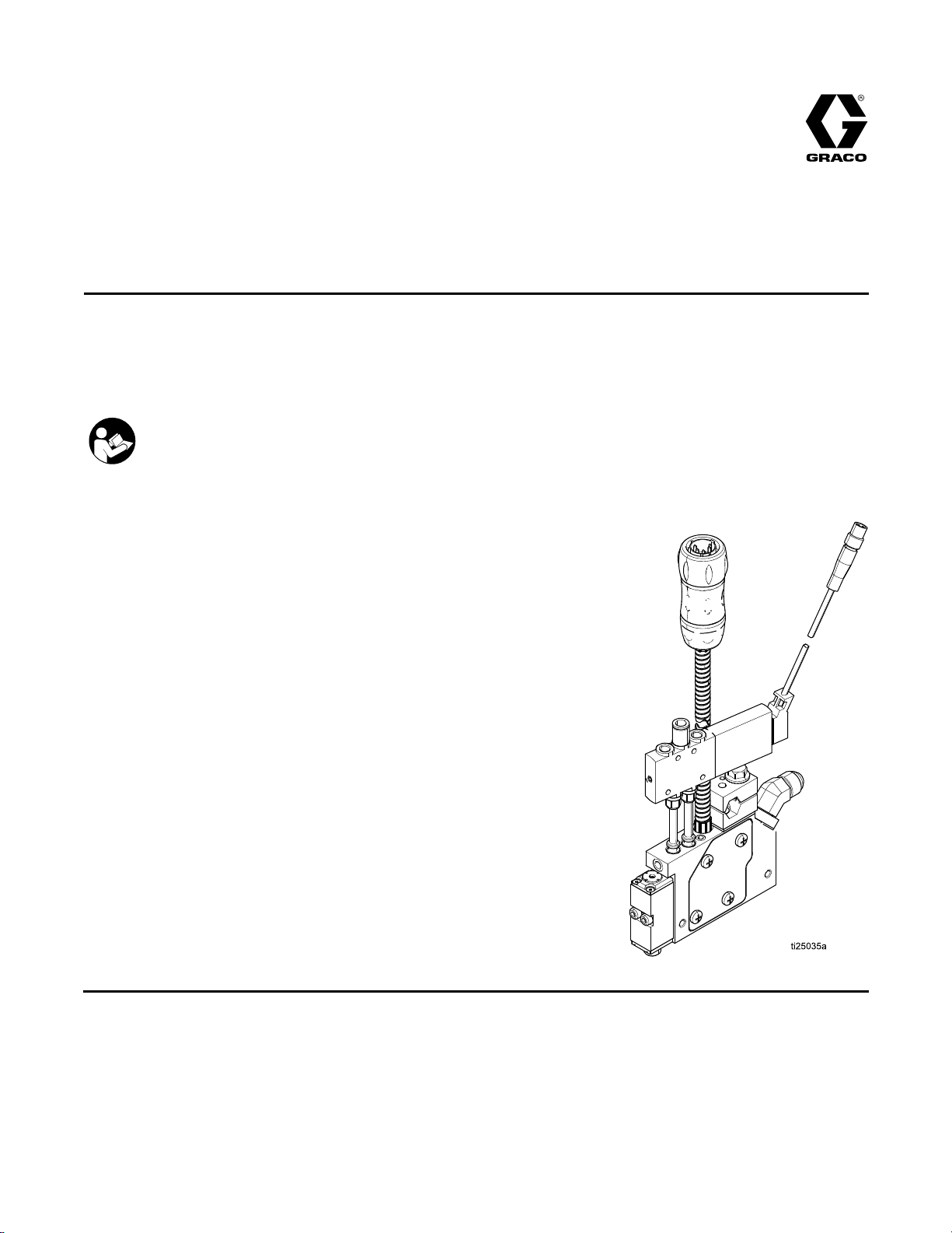
InvisiPac®
InvisiPac® InvisiPac®
Hot
Hot Hot
For
For For
Not
Not Not
See page 6 for models, approval
information and working pressure
ratings.
Melt
Melt Melt
dispensing
dispensing dispensing
approved
approved approved
Important
Important Important
Readallwarningsandinstructionsinthismanualandinrelated
manuals.Savetheseinstructions.
GM100
GM100 GM100
Applicator
Applicator Applicator
hot
melt
hot hot
for
use
for for
use use
Safety
Safety Safety
adhesive.
melt melt
adhesive. adhesive.
explosive
in ininexplosive explosive
Instructions
Instructions Instructions
Plug
Plug Plug
Free™
- --Free™ Free™
334627D
EN
For
professional
For For
professional professional
atmospheres
atmospheres atmospheres
use
only.
use use
only. only.
or
hazardous
or or
hazardous hazardous
locations.
locations. locations.
PROVENQUALITY.LEADINGTECHNOLOGY.
Page 2

Contents
Contents Contents
Warnings...........................................................3
Models...............................................................6
WorkingPressure........................................6
ModelApprovals..........................................6
ComponentIdentication.....................................7
Overview............................................................8
Grounding..........................................................8
Installation..........................................................9
Mounting.....................................................9
ConnectHeatedHose..................................9
RecommendedAirSetup..............................9
ConnectSolenoidValve...............................10
ConnectTriggeringDevice...........................10
BeforeUsingEquipment...............................10
Flush...........................................................11
InstallNozzle...............................................11
SelectRTD..................................................11
Operation...........................................................12
PressureReliefProcedure............................12
Maintenance......................................................13
ReplaceInletFilter.......................................13
FilterMaintenanceGuidelines.......................13
Troubleshooting..................................................14
CheckModule..............................................17
CheckNozzleandModule............................17
CheckHeater..............................................18
CheckRTD..................................................19
CheckThermalCutoff..................................19
Repair................................................................20
RequiredTools............................................20
BeforeBeginningRepair...............................20
ReplaceHeaterCartridge.............................20
ReplaceRTD...............................................21
ReplaceThermalCutoff................................21
ReplaceCordset..........................................23
ReplaceSolenoidValve...............................24
ReplaceModule...........................................24
ReplaceApplicator.......................................24
Notes................................................................25
Parts..................................................................26
SolenoidValveKits.............................................36
KitsandAccessories...........................................37
Dimensions........................................................40
TechnicalData...................................................45
GracoExtendedWarranty...................................46
2
334627D
Page 3
Warnings
Warnings Warnings
Thefollowingwarningsareforthesetup,use,grounding,maintenance,andrepairofthisequipment.The
exclamationpointsymbolalertsyoutoageneralwarningandthehazardsymbolsrefertoprocedure-specic
risks.Whenthesesymbolsappearinthebodyofthismanualoronwarninglabels,referbacktothese
Warnings.Product-specichazardsymbolsandwarningsnotcoveredinthissectionmayappearthroughout
thebodyofthismanualwhereapplicable.
WARNING
WARNING WARNING
BURN
BURN BURN
Equipmentsurfacesanduidthatisheatedcanbecomeveryhotduringoperation.Toavoid
severeburns:
•Donottouchhotuidorequipment.
ELECTRIC
ELECTRIC ELECTRIC
Thisequipmentmustbegrounded.Impropergrounding,setup,orusageofthesystemcan
causeelectricshock.
HAZARD
HAZARD HAZARD
SHOCK
SHOCK SHOCK
HAZARD
HAZARD HAZARD
Warnings
•Turnoffanddisconnectpoweratmainswitchbeforedisconnectinganycablesandbefore
servicingorinstallingequipment.
•Connectonlytogroundedpowersource.
•Allelectricalwiringmustbedonebyaqualiedelectricianandcomplywithalllocalcodes
andregulations.
SKIN
INJECTION
SKIN SKIN
INJECTION INJECTION
High-pressureuidfromdispensingdevice,hoseleaks,orrupturedcomponentswillpierce
skin.Thismaylooklikejustacut,butitisaseriousinjurythatcanresultinamputation.Get Get
immediate
immediate immediate
•Donotpointdispensingdeviceatanyoneoratanypartofthebody.
•Donotputyourhandovertheuidoutlet.
•Donotstopordeectleakswithyourhand,body,glove,orrag.
•FollowthePressure Pressure
checking,orservicingequipment.
•Tightenalluidconnectionsbeforeoperatingtheequipment.
•Checkhosesandcouplingsdaily.Replacewornordamagedpartsimmediately.
surgical
surgical surgical
HAZARD
HAZARD HAZARD
treatment.
treatment. treatment.
Pressure
Relief
Procedure
Relief Relief
Procedure Procedure
whenyoustopdispensingandbeforecleaning,
Get
334627D 3
Page 4
Warnings
WARNING
WARNING WARNING
FIRE
AND
FIRE FIRE
Flammablefumes,suchassolventandpaintfumes,inwork work
preventreandexplosion:
•Useequipmentonlyinwellventilatedarea.
•Eliminateallignitionsources;suchaspilotlights,cigarettes,portableelectriclamps,and
plasticdropcloths(potentialstaticarc).
•Keepworkareafreeofdebris,includingsolvent,ragsandgasoline.
•Donotplugorunplugpowercords,orturnpowerorlightswitchesonoroffwhenammable
fumesarepresent.
•Groundallequipmentintheworkarea.SeeGrounding Grounding
•Useonlygroundedhoses.
•Holdapplicatorrmlytosideofgroundedpailwhentriggeringintopail.Donotusepail
linersunlesstheyareantistaticorconductive.
Stop
•Stop Stop
equipmentuntilyouidentifyandcorrecttheproblem.
•Keepaworkingreextinguisherintheworkarea.
EQUIPMENT
EQUIPMENT EQUIPMENT
EXPLOSION
AND AND
EXPLOSION EXPLOSION
operation
operation operation
immediately
immediately immediately
MISUSE
MISUSE MISUSE
HAZARD
HAZARD HAZARD
work
area
area area
canigniteorexplode.Tohelp
Grounding
ifstaticsparkingoccursoryoufeelashock. ..Donotuse
HAZARD
HAZARD HAZARD
instructions.
Misusecancausedeathorseriousinjury.
•Donotoperatetheunitwhenfatiguedorundertheinuenceofdrugsoralcohol.
•Donotexceedthemaximumworkingpressureortemperatureratingofthelowestrated
systemcomponent.SeeTechnical Technical
•Useuidsandsolventsthatarecompatiblewithequipmentwettedparts.SeeTechnicalData
inallequipmentmanuals.Readuidandsolventmanufacturer’swarnings.Forcomplete
informationaboutyourmaterial,requestMSDSfromdistributororretailer.
•TurnoffallequipmentandfollowthePressure Pressure
•Checkequipmentdaily.Repairorreplacewornordamagedpartsimmediatelywithgenuine
manufacturer’sreplacementpartsonly.
•Donotalterormodifyequipment.Alterationsormodicationsmayvoidagencyapprovals
andcreatesafetyhazards.
•Makesureallequipmentisratedandapprovedfortheenvironmentinwhichyouareusingit.
•Useequipmentonlyforitsintendedpurpose.Callyourdistributorforinformation.
•Routehosesandcablesawayfromtrafcareas,sharpedges,movingparts,andhotsurfaces.
•Donotkinkoroverbendhosesorusehosestopullequipment.
•Keepchildrenandanimalsawayfromworkarea.
•Complywithallapplicablesafetyregulations.
TOXIC
TOXIC TOXIC
Toxicuidsorfumescancauseseriousinjuryordeathifsplashedintheeyesoronskin,
inhaled,orswallowed.
FLUID
FLUID FLUID
OR
FUMES
OR OR
FUMES FUMES
Technical
HAZARD
HAZARD HAZARD
Data
Data Data
Pressure
inallequipmentmanuals.
Relief
Relief Relief
Procedure
Procedure Procedure
whenequipmentisnotinuse.
•ReadMSDSstoknowthespecichazardsoftheuidsyouareusing.
•Storehazardousuidinapprovedcontainers,anddisposeofitaccordingtoapplicable
guidelines.
4
334627D
Page 5

WARNING
WARNING WARNING
PERSONAL
PERSONAL PERSONAL
Wearappropriateprotectiveequipmentwhenintheworkareatohelppreventseriousinjury,
includingeyeinjury,hearingloss,inhalationoftoxicfumes,andburns.Thisprotective
equipmentincludesbutisnotlimitedto:
•Protectiveeyewear,andhearingprotection.
•Respirators,protectiveclothing,andglovesasrecommendedbytheuidandsolvent
manufacturer.
PROTECTIVE
PROTECTIVE PROTECTIVE
EQUIPMENT
EQUIPMENT EQUIPMENT
Warnings
334627D 5
Page 6
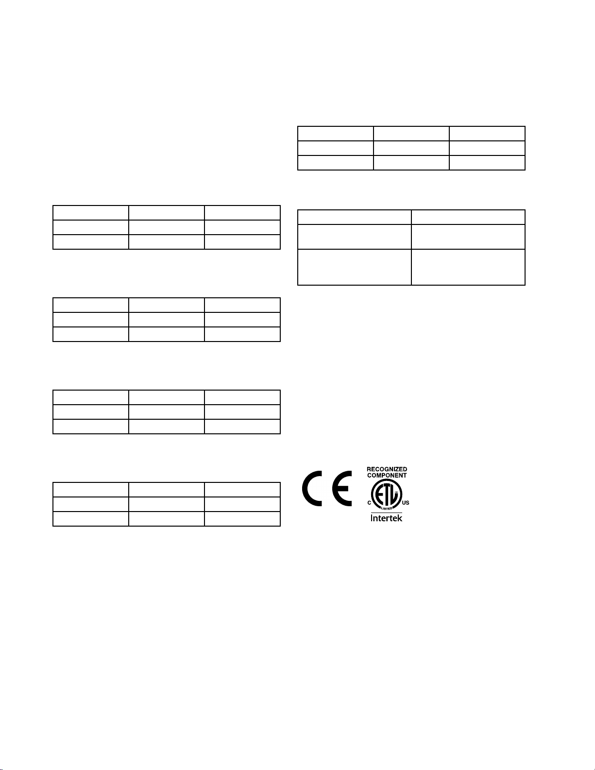
Models
Models
Models Models
Allmodelsusea240Vheater.
Low
Prole
Low Low
Prole Prole
Dual
- --Dual Dual
ApplicatorswithNi120RTDtypescomewitha6–pin
rectangularcordset(24X040forslim,24X761for
standardDual,and24W088forallothermodels).
Slim
Slim Slim
Dual
Dual Dual
Quad
Quad Quad
(Single)
(Single) (Single)
24UPart
24UPart 24UPart
25B021
25B024Ni120
Part
Part Part
25B075
25B301Ni120
Part
Part Part
25B077
25B303Ni120
RTD
Type
RTD RTD
Type Type
Pt100(385)24VDC
RTD
Type
RTD RTD
Type Type
Pt100(385)24VDC
RTD
Type
RTD RTD
Type Type
Pt100(385)24VDC
Solenoid
Solenoid Solenoid
24VDC
Solenoid
Solenoid Solenoid
24VDC
Solenoid
Solenoid Solenoid
24VDC
Part
Part Part
25B027
25B030Ni120
Related
Related Related
Valve
Valve Valve
Valve
Valve Valve
Valve
Valve Valve
Manual
Manual Manual
332072InvisiPacHeatedHose
333347InvisiPacHM25
Working
Working Working
Maximum
Maximum Maximum
1500psi(10.3MPa,103bar)
Maximum
Maximum Maximum
80psi(0.5MPa,5.5bar)
Minimum
Minimum Minimum
65psi(0.44MPa,4.4Bar)
Number
Number Number
Working
Working Working
Working
Working Working
Working
Working Working
RTD
RTD RTD
Pt100(385)24VDC
Manuals
Manuals Manuals
Pressure
Pressure Pressure
Fluid
Fluid Fluid
Air
Air Air
Air
Air Air
Type
Type Type
Pressure:
Pressure: Pressure:
Pressure:
Pressure: Pressure:
Pressure:
Pressure: Pressure:
Solenoid
Solenoid Solenoid
24VDC
Description
Description Description
Instructions-Parts
Tank-FreeHotMelt
DeliverySystem
Valve
Valve Valve
Low
Prole
Low Low
Prole Prole
Part
Part Part
25B033
25B036Ni120
Quad
- --Quad Quad
RTD
Type
RTD RTD
Type Type
Pt100(385)24VDC
Model
Model Model
Solenoid
Solenoid Solenoid
24VDC
Valve
Valve Valve
Approvals
Approvals Approvals
6 334627D
Page 7
ComponentIdentication
Component
Component Component
Identication
Identication Identication
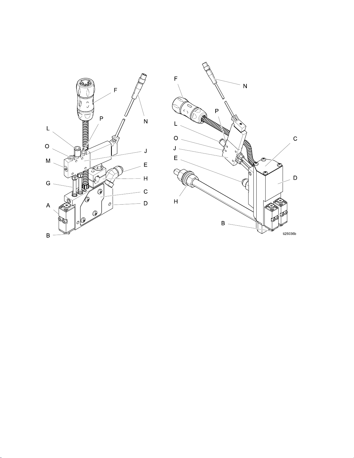
Figure1SlimModelShownonLeft,DualLowProle
ModelShownonRight
AModule
BFluidoutlet
CFluidlter
D
E
F
Manifold
Fluidinlet(9/16–18,—6JIC,37°are)
Cordset
G
H
J
L
MManualoverrideswitch
N
OAirCloseExhaustPort
P
Airtubes
Mountingclamp(1/2in.diameterbar)
Solenoidvalve(24VDC)
Airinlet(1/4in.diametertubing)
M8Solenoidvalveelectricalconnector
AirOpenExhaustPort
334627D
7
Page 8
Overview
Overview
Overview Overview
Theapplicatorusestheair-opened,airclosedmode
ofoperation.Itusesave-wayexhaustingsolenoid
tocontrolthepistoninsidethevalve.Fluidisltered
throughthemanifoldlter(C)beforeenteringthe
valveuidinletport.Thentheuidislteredonenal
timethroughthemodulelter,whichislocatedin
eachmodule,directlybeforetheballandseat.
Whenairmovesthepistonandrodfromitsseat,
itopenstheuidoutlet.Toturnofftheuid,the
solenoidredirectsairtothetopofthepiston.The
airandspringworktogethertopushthepistonand
rodintotheseat.
Theapplicatorshouldberigidlymountedand
remotelyoperatedbyameltersystemandtriggering
device.Themeltersystemprovidespressurizeduid
tothevalve.Thetriggeringdevicecontrolstheuid
owbyopeningandclosingthesolenoidvalve.
Grounding
Grounding Grounding
Theequipmentmustbegroundedtoreducethe
riskofstaticsparkingandelectricshock.Electric
orstaticsparkingcancausefumestoigniteor
explode.Impropergroundingcancauseelectric
shock.Groundingprovidesanescapewireforthe
electriccurrent.
Pump:
•Pump: Pump:
Applicator:
•Applicator: Applicator:
Air
•Air Air
recommendations.
Fluid
•Fluid Fluid
Solvent
•Solvent Solvent
code.Useonlyconductivemetalpails,placed
onagroundedsurface.Donotplacethepail
onanon-conductivesurface,suchaspaperor
cardboard,whichinterruptsgroundingcontinuity.
followmanufacturer’srecommendations.
groundedthroughelectricalconnection.
compressor:
compressor: compressor:
supply
supply supply
pails
pails pails
followmanufacturer’s
container:
container: container:
used
used used
when
when when
followlocalcode.
ushing:
ushing: ushing:
followlocal
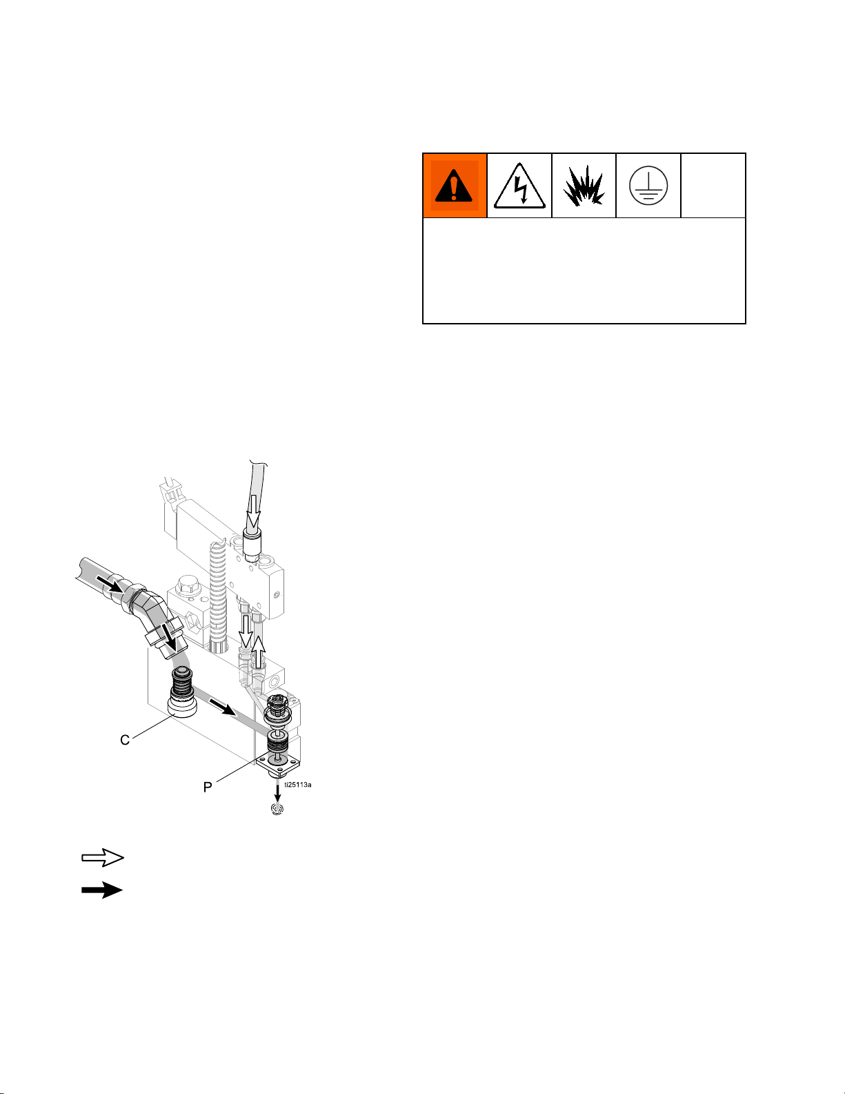
Figure2AirandFluidFlow
Air
Air Air
Fluid
Fluid Fluid
To
maintain
•To To
maintain maintain
relieving
relieving relieving
electricalpowerconnectoraregroundedproperly.
grounding
grounding grounding
pressure:
pressure: pressure:
continuity
continuity continuity
ensuremountingmanifoldand
when
ushing
when when
ushing ushing
or
or or
8 334627D
Page 9
Installation
Installation
Installation Installation
Mounting
Mounting Mounting
NOTICE
NOTICE NOTICE
Topreventheattransferringintoothercomponents
ofthepackagingline,ensurethattheinsulatoris
installed.
Low
Prole
Low Low
Prole Prole
toadjustnutsthatcontrolpositionofapplicatoron
threadedrod.
All
Other
All All
Other Other
Mountmanifoldonuptoa1/2in.(12mm)diameter
barusingmountingclamp(H)toholdtheapplicator
inplaceandensureadhesiveisappliedproperly.
Foroptimalmountingstrengthofaslimmodel,use
a7/16hexbar.
NOTE:
NOTE: NOTE:
modelsusea5mmAllenwrench.
1.Useanappropriatewrenchtoloosenthe
mountingclampandslidetheapplicatoronthe
mountingbar.
2.Tightenthemountingclamp.Torqueto144in-lb
(16.2N•m).
NOTE:
NOTE: NOTE:
applicatorformaintenanceandrepair.
Models:
Models: Models:
Models:
Models: Models:
SlimStandardDualandStandardQuad
Provideenoughroomtoaccesssidesof
Usea3/4in.(19mm)wrench
Seethefollowinginstructions.
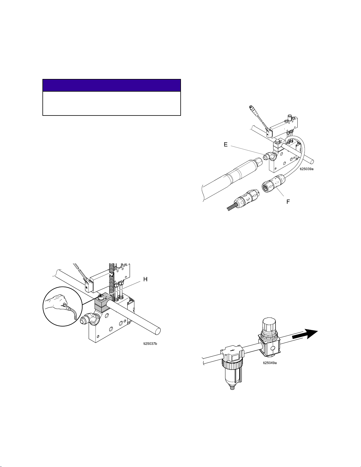
Connect
Connect Connect
1.Connectthehoseuidoutlettothemanifolduid
inlet(E).Usetwo11/16in.wrenchestotighten
thehosetting.
Figure4ConnecttheHeatedHose
2.Connectthecordset(F)tothehose.
3.Connectthehoseinlettothemeltersystem
outlet.Seetheheatedhosemanualfor
installationguidelines.
4.Connectthehosecordsettomelter.Seethe
heatedhosemanualforinstallationguidelines.
Heated
Heated Heated
Hose
Hose Hose
Recommended
Recommended Recommended
1.Connecttubingfromtheairlter(Gracopart
106148)totheairregulator.
Figure3MountingClamp
Figure5ConnecttheAirSupply
2.Settheairregulatorto80psi(5.5Bar,0.5MPa).
3.Connecttubingfromtheairregulatortothe
applicatorsolenoid.
334627D 9
Air
Setup
Air Air
Setup Setup
Page 10
Installation
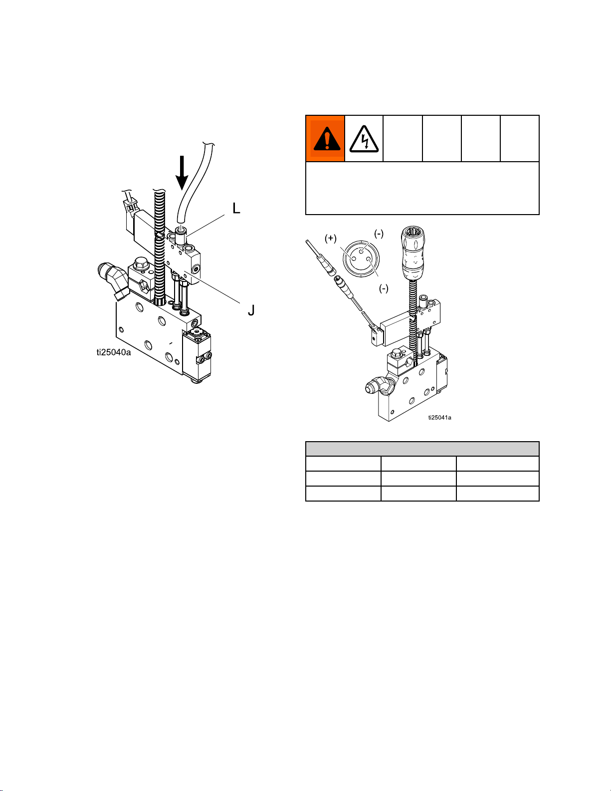
Connect
Connect Connect
1.Connect1/4in.diameterairsupplytubingtoa
clean,dry,andnon-lubricatedairsupplyandto
thepush-to-connectairinlettting(L).
Solenoid
Solenoid Solenoid
Valve
Valve Valve
Connect
Connect Connect
AllGM100valvesusea24VDCsolenoidvalve.
Improperelectricalconnectioncanresultinelectric
shock.Allelectricalwiringmustbedonebya
qualiedelectricianandcomplywithalllocalcodes
andregulations.
Triggering
Triggering Triggering
Device
Device Device
Figure6AirInletFitting
2.Connectsolenoidvalve(J)to24VDCsignal.
SeeConnectTriggeringDevice,page10.
NOTE:
NOTE: NOTE:
applicator.Thettingcanbechangedusinga5
mmAllenwrench.
A6mmtubettingisincludedwiththe
Figure7SolenoidValveElectricalConnector
Standard
Standard Standard
Terminal
Terminal Terminal
Plus(+)24VSupply
Minus(-)
Before
Before Before
Theequipmentwastestedwithcanolaoil,whichis
leftintheuidpassagestoprotectparts.Toavoid
contaminatingyouruidwithoil,primetheequipment
withhotmeltuntilalloftheoilispushedoutbefore
usingtheequipment.SeeFlush,page11.
Cable
Cable Cable
ReturnBlue/Black
Using
Using Using
Wiring
Wiring Wiring
Function
Function Function
Equipment
Equipment Equipment
Colors
Colors Colors
M8
M8 M8
Brown
10 334627D
Page 11
Installation
Flush
Flush Flush
NOTE:
NOTE: NOTE:
temperaturesetpointhasbeenachieved.Cycling
themodulebelowthetemperaturesetpointmay
causeprematuresealleakage.
1.Disconnectorturnoffthedevicewhichtriggers
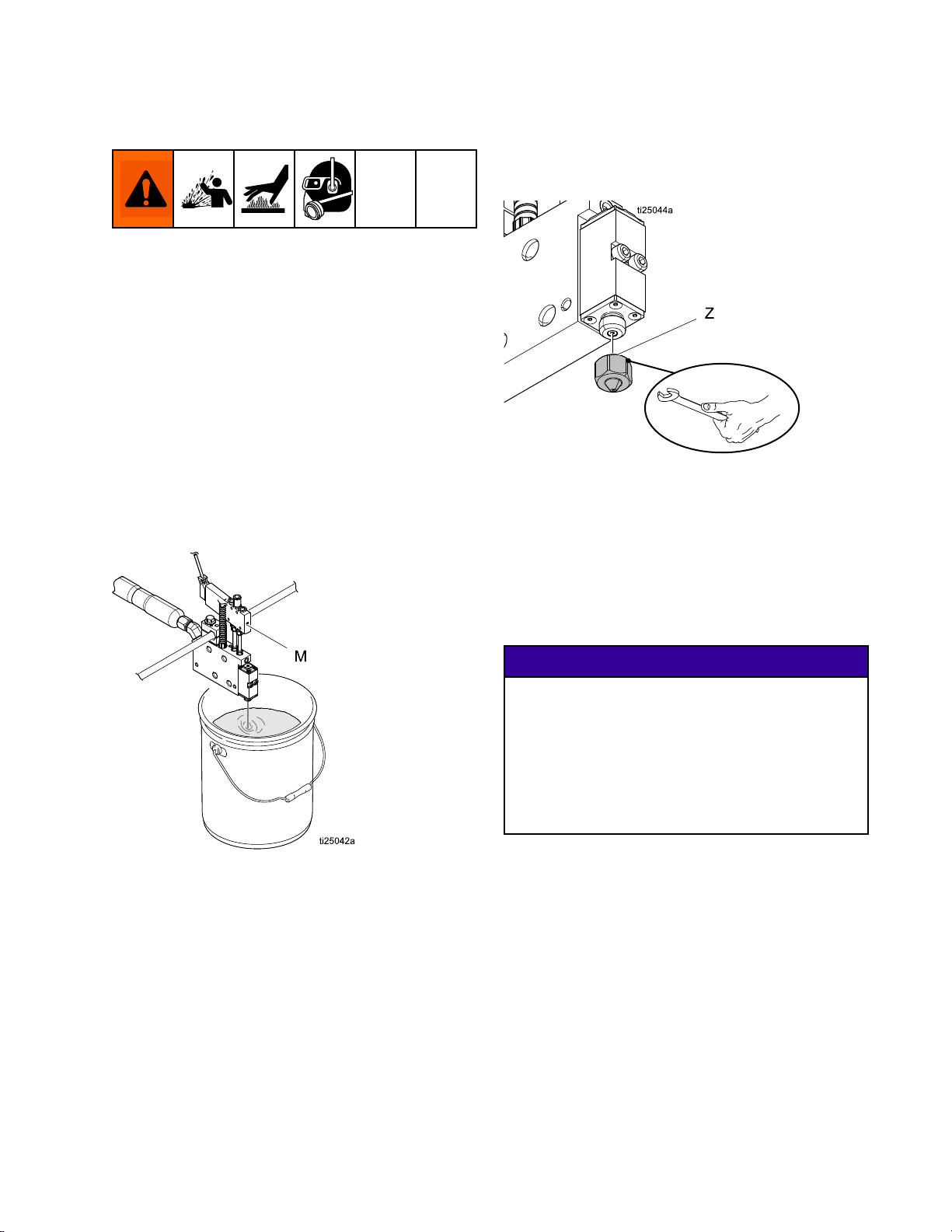
2.Ensurethenozzle(Z)isremoved.
3.Heatthesystemtoworkingtemperature.
4.Placewastecontainerundertheapplicatorto
5.Pressthemanualoverrideswitch(M)tomanually
6.Dispensehotmelt(adhesive)untilitisclean.
DoNOTcyclethemoduleuntilthe
thesolenoidvalve.
catchtheadhesive.
triggerthesolenoidvalve.
Install
Install Install
Use1/2in.wrenchtoinstallnozzle.See
KitsandAccessories,page37.
Figure9InstallNozzle
Select
Select Select
NOTE:
NOTE: NOTE:
Nozzle
Nozzle Nozzle
RTD
RTD RTD
ForInvisiPacsystemsonly.
Figure8Flush
IdentifyRTDtypeusedinapplicatoronthesystem
AdvancedDisplayModule(ADM).TheRTDtypeis
listedonthemanifoldcoverplate.
NOTICE
NOTICE NOTICE
AnincorrectRTDsettingwillcausethesystem
tobeincapableofmaintainingthetemperature
setting.Theapplicatormayoverheatandtripthe
thermalcutoff,iftheapplicatorusesaPT100(385)
andNI120isselectedontheADMSetupscreen.
Theapplicatormayunder-heatiftheapplicator
usesaNI120andPT100(385)isselectedonthe
ADMSetupscreen.
•IfPT100(385)islisted,selectPT100(385)inthe
ADMSetupscreens.
•IfNI120islisted,selectNI120intheADMSetup
screens.
334627D
11
Page 12
Operation
Operation
Operation Operation
Pressure
Pressure Pressure
Thisequipmentstayspressurizeduntilpressure
ismanuallyrelieved.Tohelppreventserious
injuryfrompressurizeduid,suchasskininjection,
andsplashinguid,followthePressureRelief
Procedurewhenyoustopsprayingandbefore
cleaning,checking,orservicingtheequipment.
1.Depressurizehotmeltsystem.
Relief
Relief Relief
FollowthePressureReliefProcedure
wheneveryouseethissymbol.
Procedure
Procedure Procedure
2.Closethebleed-typemasterairvalve.
3.Actuatetheapplicatorrepeatedlyuntilnouid
ows.
4.Ifyoususpectthemodulenozzleisclogged,
removenozzleandthenactuatethemoduleto
relievepressure.
5.Ifyoususpectthemoduleoruidhoseis
cloggedorthatpressurehasnotbeenfully
relievedafterfollowingthestepsabove,VERY
SLOWLYlooseninlettting,inletlter,orhose
endcouplingtorelievepressuregradually,
thenloosencompletely.Clearhoseormodule
obstruction.
6.Turnoffairpressuretothesolenoidvalve.
12
334627D
Page 13
Maintenance
Maintenance Maintenance
Materialinsidetheapplicatorcanbenearsetpoint
temperature.Wearprotectiveclothingtoavoid
severeburns.
Daily:
Daily: Daily:
Cleanhotmeltfromexteriorofapplicator.
Weekly:
Weekly: Weekly:
Inspecttheapplicator,uidlines,cordset,
andsolenoidcableforwearordamage.See
Repair,page20forinstructions.
Maintenance
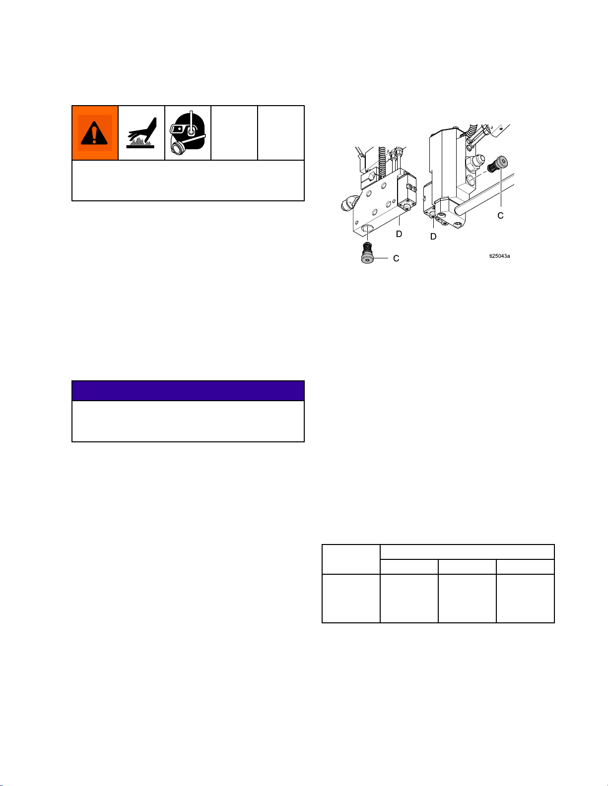
2.Removedirtylter(C)frommanifold(D).
Figure10InletFilter
3.Applyathincoatingofhigh-temperaturelubricant
tosealsonthenewlter(C)andinstallinthe
manifold(D).Torqueto30in.-lb(3.4N∙m),using
a5/32in.(4mm)Allenwrench.
Replace
Replace Replace
Removethelterwhentheapplicatorishot.Ifthe
applicatoriscold,theadhesivewillbehardandthe
ltermaybedifculttoremoveordamaged.
1.Disabletheapplicator.See
BeforeBeginningRepair,page20.
Inlet
Inlet Inlet
Filter
Filter Filter
NOTICE
NOTICE NOTICE
Filter
Filter Filter
These recommendations are service level guidelines
- actual service levels required in your factory
will vary based on environmental and operating
conditions. High or low volume adhesive usage, as
well as adhesives that contain a powdered release
agent or are otherwise dusty, will have an impact
on the frequency of lter maintenance. To establish
a preventative maintenance cycle tailored to your
environment, Graco recommends inspecting lters
every 4 weeks after installation and replacing when
necessary. Document replacement intervals and
use this as your preventative maintenance schedule
moving forward.
Manifold
lter
Maintenance
Maintenance Maintenance
Environment
Environment Environment
Clean
Clean Clean
Replace
lterevery
six
six six
months
Guidelines
Guidelines Guidelines
Classication
Classication Classication
Moderate
Moderate Moderate
everyfour four
Replace
lter
four
months
Replace
everytwo two
Dusty
Dusty Dusty
lter
months
two
334627D 13
Page 14
Troubleshooting
Troubleshooting
Troubleshooting Troubleshooting
Problem
Problem Problem
Noadhesiveorincorrect
amountofadhesiveoutofall
moduleswhentriggered
Cause
Cause Cause
PluggedmanifoldlterReplacemanifoldlter.See
ReplaceInletFilter,page13.
CloggedhoseCleanorreplacehose.
Failedsolenoidvalve
Nosignaltosolenoidvalve
Incorrectsolenoidvalvewiring
Incorrectsignaltosolenoidvalve
SolenoidmuferpluggedCheckandreplacemufers.
NouidpressureCheckadhesivedeliverysystem.
Heaterfailure(coldapplicator)Checkandreplace
Noairtosolenoidvalve
DirtyorfaultytriggeringdeviceCheck,clean,orreplacetriggering
Solenoidvalveconnected
incorrectly
Checkforcorrectoperation.Clean
orreplace.
Checksolenoidvalveforcorrect
operation.
Checksolenoidvalvewiring.
Checkif24VDC.
heatercartridges.See
ReplaceHeaterCartridge,page20.
Checkairsupply.
device.
Checksolenoidvalveairconnections.
Solution
Solution Solution
Noadhesiveorincorrect
amountofadhesiveoutof
one/somemoduleswhen
triggered
Adhesiveoutofone/some
moduleswhennottriggered
14
CloggedmanifoldpassageCleanorreplacemanifold.
Pluggednozzle
Failedmoduleinclosedposition
PluggedmodulelterReplacemodule.See
CloggedmanifoldpassageCleanorreplacemanifold.
Failedmoduleinopenposition
Adhesivepressuretoohigh
Cleanorreplacenozzle.
Checkforcorrectoperation.
Cleanorreplace.See
CheckModule,page17.
ReplaceModule,page24.
Cleanorreplacemodule.See
ReplaceModule,page24.
Checkandreduceuidpressure.
334627D
Page 15

Troubleshooting
Problem
Problem Problem
Applicatorwillnotheat
Applicatoroverheats
Cause
Cause Cause
HeaterfailureCheckandreplace
heatercartridge.See
ReplaceHeaterCartridge,page20.
Loosecordsetconnection
RTDfailureCheckandreplaceRTD.See
IncorrectRTDforadhesivedelivery
system
ThermalcutofffailureCheckandreplace
WrongRTDtypeselected
HeaterfailureCheckandreplace
RTDfailureCheckandreplaceRTD.See
IncorrectRTDforadhesivedelivery
system
Checkconnection.
CheckRTD,page19.
CheckdeliverysystemRTD
requirement
thermalcutoff.See
ReplaceThermalCutoff,page21.
CheckRTDtypesettingsonthe
system.Changeifnecessary.See
SelectRTD,page11.
heatercartridge.See
ReplaceHeaterCartridge,page20.
CheckRTD,page19.
CheckdeliverysystemRTD
requirement.
Solution
Solution Solution
Applicatorunder-heats
Adhesiveleakingfrom
applicator
Incorrectpowertoheater
WrongRTDtypeselected
HeaterfailureCheckandreplace
RTDfailureCheckandreplaceRTD.
IncorrectRTDforadhesivedelivery
system
Incorrectpowertoheater
WrongRTDtypeselected
Moduleo-ringfailureCheckandreplaceo-ring.See
InletttinglooseTightentting.
Manifoldltero-ringfailureCheckandreplaceo-ring.
NozzlelooseTightennozzle.
Checkandcorrectpower.
CheckRTDtypesettingsonthe
system.Changeifnecessary.See
SelectRTD,page11.
heatercartridge.See
ReplaceHeaterCartridge,page20
CheckdeliverysystemRTD
requirement.
Checkandcorrectpower.
CheckRTDtypesettingsonthe
system.Changeifnecessary.See
SelectRTD,page11.
ReplaceModule,page24.
334627D 15
Page 16

Troubleshooting
Problem
Problem Problem
Speedhasreducedonone
module
Adhesiveoutofallmodules
whennottriggered
Cause
Cause Cause
Lowairpressuretosolenoidvalve
LowuidpressureCheckadhesivedeliverysystem
Lowapplicatortemperature
PluggedmanifoldlterReplacemanifoldlter(see
Modulepistonsealairleak
SolenoidvalvefailureCheckandreplacesolenoidvalve.
Adhesivepressuretoohigh
Solenoidvalveconnected
incorrectly
ModulefailureCheckandreplaceallmodules.See
Noairtosolenoidvalve
Checkairsupply
Checkheatoperation.See
“Applicatorwillnotheat”sectionin
Troubleshooting,page14.
ReplaceInletFilter,page13).
Checksolenoidaircloseexhaustport
(O).SeeReplaceModule,page24.
Checkandreduceuidpressure.
Checksolenoidvalveairconnections.
CheckModule,page17.
Checkairsupply.
Solution
Solution Solution
16 334627D
Page 17

Troubleshooting
Check
Check Check
Checkthemoduleoperationtoverifyifthemodule
hasfailedandneedstobereplaced.
1.Visuallycheckforthepresenceofglueinthe
2.Verifythattheairpressuretothesolenoidvalve
Module
Module Module
weephole(W).
NOTE:
NOTE: NOTE:
replaced.SeeReplaceModule,page24.
is65–80psi(4.4–5.5bar,0.44–0.55MPa).
Ifglueispresent,themoduleneedstobe
6.Removethenozzle.
7.Pressthemanualover-rideswitchtotriggerthe
module.Ifglueowsfromtheseat,themodule
isfunctioningproperly.
Check
Check Check
Triggertheapplicatorwithoutthenozzletodetermine
ifthenozzleormoduleisclogged.
1.Disableapplicatorassembly.See
2.Usea1/2in.wrenchtoloosenthenozzleand
Nozzle
Nozzle Nozzle
BeforeBeginningRepair,page20.
removebyhand.
and
Module
and and
Module Module
Figure11CheckModule
3.Verifythatthereisairpressuretothemotor,
whichwillverifythatthereisuidpressure.
4.Makesurethesystemisatthecorrect
temperature.
5.Whilelookingintheweepholepressthesolenoid
valvemanualoverrideswitch(M)tomanually
triggertheapplicator.
NOTE:
NOTE: NOTE:
movesthenthemoduleisfunctioningproperly.If
theroddoesnotmove,themoduleneedstobe
replaced.SeeReplaceModule,page24.
Lookthroughtheweephole.Iftherod
Figure12
3.Connectthepowerandsolenoidcable.
4.Returntheapplicatorbackintooperation.
5.Triggertheapplicator.
a.Ifadhesiveows,cleanthenozzleand
reinstallonthemodule.
b.Ifadhesivedoesnotow,themoduleis
cloggedandneedstobereplaced.See
ReplaceModule,page24.
334627D
17
Page 18

Troubleshooting
Check
Check Check
Checkthecontinuityoftheheatertoverifyproper
resistance.Ifthereisnocontinuity,theheaterhas
failedandneedstobereplaced.
1.Disableapplicator.See
2.Checkresistanceoftheheaterusinga
3.Replacetheheatercartridgeifthe
Cordset
Cordset Cordset
24W087,
24X039,
or24X760
Pt100
(385)RTD
Cordset
Heater
Heater Heater
BeforeBeginningRepair,page20.
multi-meterbetweenthepinsofthecordset
connector.Seeconnectorsillustrationsincordset
pintables.
resistancereadingisoutsidethe
rangeorifthereisnocontinuity.See
ReplaceHeaterCartridge,page20.
Check
Check Check
Pins
Pins Pins
AandC
Model
Model Model
SlimModels
DualandDual
LowProle
Models
Quadand
Quadlow
ProleModels
Table
Table Table
RTD
RTD RTD
Pin
Pin Pin
A
B
C
D
E
Table
Table Table
Cordset
Cordset Cordset
Pin
Pin Pin
Resis-
Resis- Resistance
tance tance
Values
Values Values
365–405
Ohms
180–200
Ohms
145–165
Ohms
1
2Heat-
3
5
GGround
24W087,
1 1124W087, 24W087,
Cordset
Cordset Cordset
Description
Description Description
ThermalCutoff
Ground
Heat
RTD(White)
RTD(Red)
24W088,
2 2224W088, 24W088,
Description
Description Description
ThermalCutoff
RTD(White)
RTD(Red)
24X039,
24X039, 24X039,
24X040,
24X040, 24X040,
24X760,
or oror24X760, 24X760,
24X761,
or oror24X761, 24X761,
Pt
100
Pt Pt
Ni
Ni Ni
(385)
100 100
(385) (385)
120
RTD
120 120
RTD RTD
24W088,
24X040,or
24X761Ni
120RTD
Cordset
1and2
SlimModels
DualandDual
LowProle
Models
Quadand
Quadlow
ProleModels
365–405
Ohms
180–200
Ohms
145–165
Ohms
18 334627D
Page 19

Troubleshooting
Check
Check Check
CheckthecontinuityoftheRTDtoverifyproper
resistance.Ifthereisnocontinuity,theRTDhas
failedandneedstobereplaced.
1.Disabletheapplicator.See
2.CheckresistanceoftheRTDusingamulti-meter
RTD
RTD RTD
BeforeBeginningRepair,page20.
betweenthepinsofthecordsetconnector.See
connectorsillustrationsincordsetpintables.
Cordset
Cordset Cordset
24W087,
24X039,or
24X760Pt
100(385)
RTDCordset
24W088,
24X040,or
24X761Ni
120RTD
Cordset
Check
Check Check
DandE107-115
3and5130-140
Pins
Pins Pins
Resistance
Resistance Resistance
Values
Values Values
At
At At
Temperature
Temperature Temperature
ohms
ohms
Check
Check Check
Ifworkingproperly,thecutoffwilltripat500°F(260°
C)andrestat420°F(216°C).Iffailureissuspected,
allowtheapplicatortocoolandthencheckthe
continuityofthethermalcutofftoverifyithasnot
failed.Ifthereisnocontinuity,thecutoffhasfailed
andneedstobereplaced.
1.Disabletheapplicator.See
2.Removecoverplate.
3.Checkforcontinuityusingamulti-meterbetween
Room
Room Room
Cordset
Cordset Cordset
24W087,24X039,or
24X760Pt100(385)
RTDCordset
24W088,24X040,or
24X761Ni120RTD
Cordset
Thermal
Thermal Thermal
BeforeBeginningRepair,page20.
pinofcordsetconnectorandthewirefromthe
thermalcutoffthatconnectstotheheaterlead.
Cutoff
Cutoff Cutoff
Check
Check Check
A
1
Pins
Pins Pins
3.ReplacetheRTDiftheresistancereadingis
outsidetherange,orifthereisnocontinuity.See
ReplaceRTD,page21.
334627D 19
Page 20

Repair
Repair
Repair Repair
Required
Required Required
•Phillipsscrewdriver
•Flatbladescrewdriver
•3mm,4mm,and5mmAllenwrenches
•10mm,1/2in.11/16in.,and3/4in.wrenches
•Torquewrenches
•Wastecontainer
•High-temperatureanaerobicthreadsealant
•High-temperaturelubricant
•Anti-seize
•Crimptool
Before
Before Before
Tools
Tools Tools
Beginning
Beginning Beginning
Repair
Repair Repair
Replace
Replace Replace
1.Disabletheapplicator.
SeeBeforeBeginningRepair,page20.
2.UseaPhillipsscrewdrivertoremovethefour
screws(15)andmanifoldcoverplate(18).
Heater
Heater Heater
Cartridge
Cartridge Cartridge
Materialinsidetheapplicatorcanbenearsetpoint
temperature.Wearprotectiveclothingtoavoid
severeburns.
1.Turnoffthemeltersystem.Seemeltermanual
forshutdowninstructions.
2.Relievepressure.See
PressureReliefProcedure,page12.
3.Disconnectthecordset(F)fromtheheatedhose.
Figure13DisconnectCordset
4.DisconnectM8solenoidelectricalconnector(N).
3.Removetheheatercartridges(3)fromthe
manifold(1).
NOTE:
NOTE: NOTE:
leadlengths.
4.Removebuttsplices(4)fromheaterwires(3),
thermalcutoff(29),andcordsetwireleads(17).
5.Crimpnewheaterwiresintonewsplices(4).See
wiringdiagram.
6.Insertthenewheatercartridges(3)intothe
manifold(1).
NOTE:
NOTE: NOTE:
cartridge.
7.Reinstallthemanifoldcoverplate(18).
8.Reconnectthecordset(17)totheheatedhose.
9.ReconnecttheM8solenoidelectricalconnector
(N).
Notetheplacementoftheheatersand
NOTICE
NOTICE NOTICE
Topreventashorttogroundandblowinga
MZLPfuse,ensurebarewiresarecovered
andberglasstapeandsleevesarecentered
oversplices.
Donotapplythermalgreasetotheheater
20 334627D
Page 21

Repair
Replace
Replace Replace
TheRTDisreplacedbyreplacingtheentirecordset.
SeeReplaceCordset,page23,forinstructions.
Replace
Replace Replace
1.Disabletheapplicator.See
BeforeBeginningRepair,page20.
2.UseaPhillipsscrewsdrivertoremovethefour
screws(15)andmanifoldcoverplate(18).
3.Removebuttsplices(4)fromheaterwires(3)
andcordsetwireleads(17).
4.Crimpwires.SeeWiringDiagram.
Topreventashorttogroundandblowinga
MZLPfuse,ensurebarewiresarecovered
withberglasstape(32)andsleeves(30)are
centeredoverbuttsplices(4).
RTD
RTD RTD
Thermal
Thermal Thermal
Cutoff
Cutoff Cutoff
NOTICE
NOTICE NOTICE
a.Crimpbuttspliceoncordsetheaterwires
(17)andheaterwires(3).Lightpullonsplice
toensureitiscrimped.
b.Slidesleeves(30)overeachpairofwires
beforecrimping.
c.Crimpwhitewiretoonethermalcutofflead
(29).
d.Crimpotherthermalcutofflead(29)toone
heaterwire(s)(3).
e.Crimpotherheaterwire(s)toblacklead(17).
f.Wrapashortpieceofberglasstapearound
eachsplice.
g.Centersleeves(30)overeachtapedsplice.
5.Gentlypresswiresintothemanifold.Instalplate
(18)andscrews(15).
334627D
21
Page 22

Repair
Wiring
Wiring Wiring
Thermal
Thermal Thermal
Diagram
Diagram Diagram
Cutoff
Cutoff Cutoff
NOTE:
NOTE: NOTE:
useoneheater(3).
22
Slim(25B021and25B024),Quad(25B077and25B303)andLowProleQuad(25B075and25B301)
334627D
Page 23

Repair
Replace
Replace Replace
SeeFig14,page23.
NOTE:
NOTE: NOTE:
24X039isforslim100OhmRTDcontrolled
applicators.
24X040isforslim120OhmRTDcontrolled
applicators.
24X760isfordual100OhmRTDcontrolled
applicators.
24X761isfordual120OhmRTDcontrolled
applicators.
24W087isforLowProleDual,LowProleQuad,
andQuad100OhmRTDcontrolledapplicators.
24W088isforLowProleDual,LowProleQuad,
andQuad120OhmRTDcontrolledapplicators.
Makesureyouhavethecorrectcordsetbefore
replacing.
1.Disabletheapplicator.See
BeforeBeginningRepair,page20.
2.UseaPhillipsscrewdrivertoremovethefour
screws(15)andmanifoldcoverplate(18).
Cordset
Cordset Cordset
Therearesixtypesofcordsets(17):
10.Reinstallthegroundleadontothemanifold(1).
NOTE:
NOTE: NOTE:
belowthegroundringterminal.
11.InserttheRTD(17a)andthermalcutoff(29)into
themanifoldports.SeeFig14.
NOTE:
NOTE: NOTE:
thermalcutoff.
12.Inserttheheatercartridges(3)inthemanifold(1).
13.Reinstallthemanifoldcoverplate(18).
14.Reconnectthecordset(17)totheheatedhose.
15.ReconnecttheM8solenoidelectricalconnector..
Ensurethestarwasher(20)isplaced
DonotapplygreaseontheRTDor
NOTICE
NOTICE NOTICE
Donotpinchanywireswheninsertingwire
inthemanifold,topreventremovingwire
insulationordisconnectingwires.Ifwire
insulationisremoved,theRTDorheaters
couldshortoutandneedtobereplaced.
3.Usea2mmAllenwrenchtoremovetheset
screw(6)holdingthecordset(17)onthemanifold
(1).
4.UseaPhillipsscrewdrivertoremovetheground
leadandstarwasher(20)fromthemanifold(1).
Low
Prole
Low Low
Prole Prole
nexttoRTD.
5.RemovetheRTD(17a)fromthemanifold(1).
6.Disconnectthermalcutoff(29).
7.Removethecordset(17)fromthemanifold(1).
8.Installthenewcordset,RTD,andground(17)in
themanifold(1).Crimpthermalcutoffwires(29).
SeeWiringDiagram,page22forconnections.
NOTE:
NOTE: NOTE:
insertedintothemanifold.
9.Installsetscrew(6)againstthecordsetbushing
tosecurethecordset(17)tothemanifold(1).
Models
Models Models
Ensurethecordsetbushingisfully
only:
only: only:
RemovePhillipsscrew
Figure14RepairParts
334627D 23
Page 24

Repair
Replace
Replace Replace
1.Disabletheapplicator.See
BeforeBeginningRepair,page20.
2.Turnofftheairsupplytothesolenoidvalve.
3.DisconnecttheM8solenoidelectricalconnector
(N).
4.Disconnectairlinefromairtting(L).
Figure15ReplaceSolenoidValve
5.Loosenthesolenoidvalvesetscrewwitha3mm
Allenwrench,thenremovethesolenoidvalve(J).
6.Applyhightemperaturegreasetoo-ringson
solenoidtubes.
7.Installthenewsolenoidvalveintothemanifold,
thenusea3mmAllenwrenchtotightenthe
solenoidvalvesetscrew.
8.ConnecttheM8solenoidvalveelectrical
connector(N).
9.Connectthe1/4in.airlinetothesolenoid.Turn
airon.
Replace
Replace Replace
1.Disabletheapplicator.See
BeforeBeginningRepair,page20.
Solenoid
Solenoid Solenoid
Module
Module Module
Valve
Valve Valve
NOTICE
NOTICE NOTICE
Donotallowadhesivetoentertheairports,
toallowairtoowthroughvalve.Adhesivein
theairportswillobstructtheowofairand
damagethevalve.
Figure16RemoveModuleFromManifold
3.Verifythatnoglueispresentinthemanifoldair
ports.
4.Applyhightemperaturelubricanttoairsection
o-rings(2b)anduidsectiono-ring(2a)in
module(2).
NOTE:
NOTE: NOTE:
uidsectiono-ringisblack.Allo-ringsare
uoroelastomer.Thecolorisonlyusedtoidentify
thedifferenceinsize.
5.Applyanti-seizetotwoscrewthreads(22).Use
a3mmAllenwrenchtoinstallnewmodule(2)on
manifoldwithtwoscrews(22).Torqueto28–32
in.-lb(3.2–3.6N•m).
6.Connectcordset(17)totheheatedhose.
Replace
Replace Replace
1.Disabletheapplicator.See
BeforeBeginningRepair,page20.
2.Loosenthemountingbarclampandremovethe
applicatorfromthemountingbar.
3.Installnewapplicator.SeeInstallation,page9.
Airsectiono-ringsarebrownandthe
Applicator
Applicator Applicator
2.Usea3mmAllenwrenchtoremovethetwo
mountingscrews(22)andmodule(2)from
manifold(1).
24
334627D
Page 25

Notes
Notes
Notes Notes
334627D 25
Page 26

Parts
1
2
4
10
11
Parts
Parts Parts
SLIM
SLIM SLIM
(25B021,
(25B021, (25B021,
25B024)
25B024) 25B024)
Applyathincoatingoflubricanttoseals.
Applylubricanttotherst.05in.ofthethread
ofthebolts(22)beforeinstallingmodule(2).
Torqueto30+/-2in-lb(3.3+/-0.2N•m).
Torqueto15–20in-lb(1.7–2.2N•m).
26 334627D
Torqueto10–12in-lb(1.1–1.5N•m).
Torqueto144in–lb/12ft-lb(1.5N•m).
Page 27

Parts
Table
Table Table
Ref.
Ref. Ref.
1
225B241
3♦24X043
4◌
5▲
8124736
9☼24X038
10●
11●
12●
13102411
14●
15128306
16■
17
17a24X039
17b24X040
1817A518
1917B164
Slim
Parts
1 11Slim Slim
Part
Part Part
16K931
List
Parts Parts
List List
Description
Description Description
MANIFOLD,single
MODULE,AC,GM100
HEATER,rod
CONNECTOR,buttsplice
TAG,warning
SCREW,set,cup,M4x7x4
mm,sst
SOLENOID,quickdisconnect
INSULATOR,slim
CLAMP,bottom,hinged
BOLT,shcs,M6x35mm
PIN,spring,
SCREW,mach,hex,athd
SCREW,mach,phillips,pan
hd
FILTER,applicator,80mesh
CORD,set,240V,applicator,
mini
APPLICATOR,GM100,single,
24VDC,PT100(Model
25B021)
APPLICATOR,GM100,
single,24VDC,Ni120(Model
25B024)
PANEL,single
INSULATOR,electrical
Qty.
Qty. Qty.
1
1
1
3
1
1
1
1
2
1
1
1
5
1
1
Ref.
Part
Ref. Ref.
Part Part
20157021
22111119
2424P548
25103473
2616P285
2924X046
30◌
32◌
C33049
4024X456
41▲17F001
42●
●
Included in Slim Mounting Clamp Kit, see
Kits and Accessories, page 37 .
◌
Included with all Heater, Cordset, and Overtemp
Kits, see Kits and Accessories, page 37 .
♦
Included with Slim Heater Kit, see
Description
Description Description
WASHER,lock,int
SCREW,valve
FITTING,elbow,45,JIC06x
SEA06,mm
STRAP,tie,wire
SCREW,set,cup,sockethd
SWITCH,overtemp,500F,2
in.leads
SLEEVE,silicone,red,2in.
LGX,0.16in.OD
TAPE,adhesive,berglass
CABLE,M8,3–pin,5.0m
TAG,instruction
LOCKWASHER
Qty.
Qty. Qty.
1
2
1
1
1
1
3
0.25
1
1
1
Kits and Accessories, page 37 .
■
Included in Inlet Filter Kit options, see
Kits and Accessories, page 37 .
☼
For individual solenoid components, see
Solenoid Valve Kits, page 36 .
▲
1
1
Replacement Danger and Warning labels are
available at no cost.
334627D
27
Page 28

Parts
7
11
15
17
Dual
Dual Dual
(25B075,
(25B075, (25B075,
25B301)
25B301) 25B301)
Applyathincoatingoflubricanttoseals.
Applylubricanttotherst.05in.ofthethread
ofthebolts(22)beforeinstallingmodule(2).
Torqueto30+/-2in-lb(3.3+/-0.2N•m).
28 334627D
Torqueto10–12in-lb(1.1–1.5N•m).
Torqueto15–20in-lb(1.7–2.2N•m).
Page 29

Parts
Table
Table Table
Ref. Ref.
1
225B241
3♦24X242
4◌
5▲
617D782
7
8124736
9☼24X038
1124X046
12108050
13117030
1424P549
15128306
16■
17
17a24X760
17b24X761
Dual
Parts
2 22Dual Dual
Ref.
Part
Part Part
16K931
128220
List
Parts Parts
List List
Description
Description Description
MANIFOLD,dual,GM100,
machined
MODULE,AC,GM100
HEATER,rod
CONNECTOR,buttsplice
TAG,warning
PLATE,electrical,GM100,dual
INSULATOR,electrical,dual
SCREW,set,cup,M4x0.7x4
mm,sst
SOLENOID,quickdisconnect
SWITCH,overtemp,500F,with
2in.leads
WASHER,lock,spring
SCREW,shcs,M6x40
FITTING,elbow,45,JIC06x
SEA06,mm
SCREW,mach,phillips,panhd
FILTER,applicator,80mesh
CORD,set,240V,applicator,
dual,100
APPLICATOR,GM100,dual,
24VDC,PT100(Model25B075)
APPLICATOR,GM100,dual,
24VDC,Ni120(Model25B301)
Qty.
Qty. Qty.
1
2
2
3
1
1
1
1
1
1
2
2
1
6
1
1
Ref.
Part
Ref. Ref.
Part Part
20157021
22111119
26103473
27●16T205
28●16P848
2916P285
33◌
44◌
C33049
5224X456
53▲17F001
●
Included in Dual Mounting Clamp Kit, see
Kits and Accessories, page 37 .
◌
Included with all Heater, Cordset, and Overtemp
Kits, see Kits and Accessories, page 37 .
♦
Included with Dual Heater Kit, see
Kits and Accessories, page 37 .
■
Included in Inlet Filter Kit options, see
Kits and Accessories, page 37 .
☼
For individual solenoid components, see
Description
Description Description
WASHER,lock,int
SCREW,valve
STRAP,tie,wire
CLAMP,bar,housing,metric
INSULATOR,clamp,bar,
housing
SCREW,set,cup,sockethd
SLEEVE,silicone,red,2in.
LGX0.16in.OD
TAPE,adhesive,berglass
CABLE,M8,3–pin,5.0m
TAG,instruction
Qty.
Qty. Qty.
1
4
1
2
1
1
3
0.25
1
1
Solenoid Valve Kits, page 36 .
▲
Replacement Danger and Warning labels are
available at no cost.
334627D 29
Page 30

Parts
7
11
15
17
Quad
Quad Quad
(25B077,
(25B077, (25B077,
25B303)
25B303) 25B303)
Applyathincoatingoflubricanttoseals.
Applylubricanttotherst.05in.ofthethread
ofthebolts(22)beforeinstallingmodule(2).
Torqueto30+/-2in-lb(3.3+/-0.2N•m).
30 334627D
Torqueto10–12in-lb(1.1–1.5N•m).
Torqueto15–20in-lb(1.7–2.2N•m).
Page 31

Parts
Table
Table Table
Ref. Ref.
1
225B241
3♦24X758
4◌
5▲
617A618
7
8
9☼24X038
1124X046
12●108050
13●117030
1424P549
15128306
16■
17
17a24W087
17b24W088
Quad
Parts
3 33Quad Quad
Ref.
Part
Part Part
16K931
128219
124736
List
Parts Parts
List List
Description
Description Description
MANIFOLD,quad,mini,
machinehead
MODULE,AC,GM100
HEATER,240VAC,375W,8
mmdia.
CONNECTOR,buttsplice
TAG,warning,turbo
COVER,electric,GM100,quad
INSULATION,electrical,quad
SCREW,set,cup,M4x0.7x
4mm,sst
SOLENOID,quickdisconnect
SWITCH,overtemp,500Fwith
2in.leads
WASHER,lock,spring
SCREW,shcsM6X40
FITTING,elbow,45,JIC
06XSAE06,mm
SCREW,mach,phil,panhd
FILTER,applicator,80mesh
CORDSET,240V,applicator
APPLICATOR,GM100,quad,
24VDC,PT100(Model
25B077)
APPLICATOR,GM100,quad,
24VDC,Ni120(Model25B303)
Qty.
Qty. Qty.
1
4
1
3
1
1
1
1
1
1
Ref.
Part
Ref. Ref.
Part Part
20157021
22111119
26103473
27●16T205
28●16P848
2916P285
33◌
43102233
44◌
C33049
5224X456
53▲17F001
Description
Description Description
WASHER,lock,int
SCREW,valve
STRAP,tie,wire
CLAMP,bar,housing,metric
INSULATOR,clamp,bar,
housing
SCREW,set,cup,sockethd
SLEEVE,silicone,red,2in.
LGX16in.OD
BALL,stainlesssteel
TAPE,adhesive,berglass
CABLE,M8,3–pin,5.0m
TAG,instruction
Qty.
Qty. Qty.
1
8
1
2
1
1
3
2
1
1
2
●
2
Included in Quad Mounting Clamp Kit, see
Kits and Accessories, page 37 .
1
6
1
1
◌
Included with all Heater, Cordset, and Overtemp
Kits, see Kits and Accessories, page 37 .
♦
Included with Quad Heater Kit, see
Kits and Accessories, page 37 .
■
Included in Inlet Filter Kit options, see
Kits and Accessories, page 37 .
☼
For individual solenoid components, see
Solenoid Valve Kits, page 36 .
▲
Replacement Danger and Warning labels are
available at no cost.
334627D 31
Page 32

Parts
7
8
11
17
18
Low
Prole
Low Low
Prole Prole
Quad
Quad Quad
(25B033,
(25B033, (25B033,
25B036)
25B036) 25B036)
Applyathincoatingoflubricanttoseals.
Applysealanttothreads.Theheadofthe
plugneedstobeushwiththehousing.
Applylubricanttotherst.05in.ofthethread
ofthebolts(22)beforeinstallingmodule(2).
Torqueto30+/-2in-lb(3.3+/-0.2N•m).
32 334627D
Torqueto15–20in-lb(1.7–2.2N•m).
Torqueto20–30in-lb(2.2–3.3N•m).
Page 33

Parts
Table
Table Table
Ref. Ref.
1
225B241
3♦24X758
4◌
5▲
617B968
7
8124736
9☼24X038
1124X046
12●108050
13●117029
1424P615
15128306
16■
17
17a24W087
17b24W088
1817D216
20157021
21103147
22111119
Low
Prole
Quad
Parts
4 44Low Low
Prole Prole
Quad Quad
Description
Ref.
Part
Part Part
Description Description
MANIFOLD,quad,LP,mini,
machined
MODULE,AC,GM100
HEATER,240VAC,375W,8
mmdiameter
CONNECTOR,buttsplice
16K931
TAG,warning
PLATE,side,quad,LP,
GM100
128007
INSULATOR,electrical,side
plate
SCREW,set,cup,M4x0.7x
4mm,sst
SOLENOID,quickdisconnect
SWITCH,overtemp,500F,
with2in.leads
WASHER,lock,spring
SCREW,shcs,M6X25
FITTING,adapter,JIC06x
SEA06,mm
SCREW,mach,phillips,pan
hd
FILTER,applicator,mesh80
CORD,set,240V,applicator
APPLICATOR,GM100,dual,
LP,24VDC,PT100(Model
25B033)
APPLICATOR,GM100,dual,
LP,24VDC,Ni120(Model
25B036)
PLATE,back,quad,LP,
GM100
WASHER,lock,int
PLUG,pipe
SCREW,valve
List
Parts Parts
List List
Qty.
Qty. Qty.
1
4
1
3
1
Ref.
Part
Ref. Ref.
Part Part
26103473
2916P285
33◌
35●
36●
1
37●
1
1
1
38●102598
39●109570
40●100020
41●100018
1
2
2
1
10
1
1
42●100321
43102233
44◌
C33049
46128008
5224X456
53▲17F001
●
Included in Quad Mounting Clamp Kit, see
Description
Description Description
STRAP,tie,wire
SCREW,set,cup,sockethd
SLEEVE,silicone,red,2in.
LGX0.16in.OD
INSULATOR,clamp,GM100,
quad,LP
BLOCK,mounting,GM100,
quad,LP
ROD,mtg,threaded,low
prole
SCREW,cap,sockethead
WASHER,plain
WASHER,lock
WASHER,lock,spring
NUT
BALL,stainlesssteel
TAPE,adhesive,berglass
INSULATOR,electrical,back
plate
CABLE,M8,3–pin,5.0M
TAG,instructions
Qty.
Qty. Qty.
1
1
3
1
1
1
1
2
1
2
2
4
0.25
1
1
1
Kits and Accessories, page 37 .
◌
Included with all Heater, Cordset, and Overtemp
Kits, see Kits and Accessories, page 37 .
♦
Included with Quad Heater Kit, see
Kits and Accessories, page 37 .
■
Included in Inlet Filter Kit options, see
1
1
1
8
Kits and Accessories, page 37 .
☼
For individual solenoid components, see
Solenoid Valve Kits, page 36 .
▲
Replacement Danger and Warning labels are
available at no cost.
334627D 33
Page 34

Parts
7
8
11
15
17
18
Low
Prole
Low Low
Prole Prole
Dual
Dual Dual
(25B027,
(25B027, (25B027,
25B030)
25B030) 25B030)
Applyathincoatingoflubricanttoseals.
Applysealanttothreads.Theheadofthe
plugneedstobeushwiththehousing.
Applylubricanttotherst.05in.ofthethread
ofthebolts(22)beforeinstallingmodule(2).
Torqueto30+/-2in-lb(3.3+/-0.2N•m).
34 334627D
Torqueto10–12in-lb(1.1–1.5N•m).
Torqueto15–20in-lb(1.7–2.2N•m).
Torqueto20–30in-lb(2.2–3.3N•m).
Page 35

Parts
Table
Table Table
Ref. Ref.
1
225B241
3♦24X242
4◌
5▲
8124736
9☼24X038
1124X046
12●108050
13●127941
1424P615
15128306
16■
17
17a24W087
17b24W088
18
20157021
21103147
22111119
26103473
2916P285
Low
Prole
Dual
Parts
5 55Low Low
Prole Prole
Dual Dual
Description
Ref.
Part
Part Part
Description Description
MANIFOLD,dual,LP,mini,
machined
MODULE,AC,GM100
HEATER,rod
CONNECTOR,buttsplice
16K931
TAG,warning
SCREW,set,cup,M4x0.7x
4mm,sst
SOLENOID,quickdisconnect
SWITCH,overtemp,500F,
with2in.leads
WASHER,lock,spring
SCREW,shcs,M5x25
FITTING,adapter,JIC06x
SEA06,mm
SCREW,mach,phillips,pan
hd
FILTER,applicator,80mesh
CORD,set,240V,applicator
APPLICATOR,GM100,dual,
LP,24VDC,PT100(Model
25B027)
APPLICATOR,GM100,dual,
LP,24VDC,Ni120(Model
25B030)
17C165
PLATE,electrical,GM100,
dual,LP
WASHER,lock,int
PLUG,pipe
SCREW,valve
STRAP,tie,wire
SCREW,set,cup,sockethd
List
Parts Parts
List List
Qty.
Qty. Qty.
1
2
Ref.
Part
Ref. Ref.
Part Part
33◌
35●
17C164
2
36●
3
1
1
1
1
2
2
17C163
37●16V783
38●102598
39●109570
40●100020
41●100018
42●100321
43102233
1
6
1
1
44◌
C33049
46127943
5224X456
53▲17F001
●
Included in Quad Mounting Clamp Kit, see
Description
Description Description
SLEEVE,silicone,red,2in.
LGX0.16in.OD
INSULATOR,clamp,GM100,
dualLP
BLOCK,mounting,GM100,
dual,LP
ROD,mtg,threaded,low
prole
SCREW,cap,sockethead
WASHER,plain
WASHER,lock
WASHER,lock,spring
NUT
BALL,stainlesssteel
TAPE,adhesive,berglass
INSULATOR,electrical
CABLE,M8,3–pin,5.0m
TAG,instructions
Qty.
Qty. Qty.
3
1
1
1
1
2
1
2
2
2
0.25
1
1
1
Kits and Accessories, page 37 .
◌
Included with all Heater, Cordset, and Overtemp
Kits, see Kits and Accessories, page 37 .
♦
Included with Quad Heater Kit, see
Kits and Accessories, page 37 .
1
1
1
4
1
■
Included in Inlet Filter Kit options, see
Kits and Accessories, page 37 .
☼
For individual solenoid components, see
Solenoid Valve Kits, page 36 .
▲
Replacement Danger and Warning labels are
available at no cost.
1
334627D 35
Page 36

SolenoidValveKits
Ref.
Solenoid
Solenoid Solenoid
24X038,
24X038, 24X038,
Valve
Valve Valve
24
VDC
24 24
VDC VDC
Solenoid Solenoid
Kits
Kits Kits
Solenoid
Valve
Valve Valve
Ref. Ref.
1
*2
*3
*4
*5
*6
Part
Part Part
---
24X044KIT,solenoidtubewith
106560
295685
17A633
24X045KIT,solenoidcable1
Description
Description Description
VALVE,solenoid,5w,sr,
24VDC
o-rings
O-RING,packing
O-RING
FITTING,1/4
push-to-connect,M7
Qty.
Qty. Qty.
1
1
1
1
1
36 334627D
Page 37

KitsandAccessories
Kits
Kits Kits
Module
Module Module
25B241
25B241 25B241
Part
Part Part
----
111119
24R835
24T179
24X834
Cordsets
Cordsets Cordsets
CordsetsincludetheRTD.Usecrimptoolkit24W086
(purchaseseparately).
Kit
Kit Kit
24X039
24X040
24X760
24X761
24W087AllothermodelsPlatinum100
24W088Allothermodels
and
and and
Replacement Replacement
Accessories
Accessories Accessories
Replacement
Description
Description Description
MODULE
SCREW,valve
O-RING(10pack)Fluid
LUBRICANT,anti-seize
AirO-RING(10pack)
Model
Model Model
Slim
SlimNickel120Ohm
StandardDual
StandardDualNickel120Ohm
RTD
RTD RTD
Platinum100
Ohm
Platinum100
Ohm
Ohm
Nickel120Ohm
Anti
Seize
Anti Anti
- --Seize Seize
24T179
24T179 24T179
Qty.
Qty. Qty.
1
2
1
1
2
Type
Type Type
Tubewith0.5ozofanti-seizeforuseonmodule
mountingscrewsinInvisiPacapplicators.
Mufers
Mufers Mufers
24X037
24X037 24X037
Includestwomufersthatcanbeusedwithsolenoid
valvekits.
Blanking
Blanking Blanking
24W017
24W017 24W017
Usetoruntwoorthreemodulesonaquadapplicator
oronemoduleonadualapplicator.
Inlet
Inlet Inlet
Kit
Kit Kit
24P275
24P8023Pack
Plate
Plate Plate
Filter
Filter Filter
Qty.
Qty. Qty.
Single
Kit
Kit Kit
Heater
Heater Heater
Heatercartridgesforsingle,dual,andquadmodels.
Kit
Kit Kit
24X043
24X242DualLow
24X758
High
High High
24T156
24T156 24T156
Packetwith3–gramsofhightemperaturelubricant.
ForuseonsealsinInvisiPacapplicators.
334627D 37
Cartridges
Cartridges Cartridges
Model
Model Model
Slim1.75in.(44mm)
Proleand
Dual
QuadLow
Proleand
Quad
Temperature
Temperature Temperature
Length
Length Length
1.75in.(44mm)
3.1in.(79mm)
Lubricant
Lubricant Lubricant
Material
Material Material
Single
Single Single
Qty.
Qty. Qty.
1
2
1
24P615
24P548
24P547
Thermal
Thermal Thermal
Kit
Kit Kit
24X046
Inlet
Inlet Inlet
Kit
Kit Kit
Fittings
Fittings Fittings
Description
Description Description
Straight
45°
90°
Cutoff
Cutoff Cutoff
Description
Description Description
Standard
Replacement
Replacement Replacement
Kits
Kits Kits
Page 38

KitsandAccessories
Mounting
Mounting Mounting
(Slim
24X042)
(Slim (Slim
24X042) 24X042)
Ref
Ref Ref
1017A496
11
12108050
13112674
14106371
24X243
24X243 24X243
Ref
Ref Ref
1024P276
11
12108050
13117029
44
45
46
47
48
49
24P277
24P277 24P277
Ref.
Ref. Ref.
116T205
2108050
3117030
416P848
Clamp
Clamp Clamp
Part
Part Part
---
(Dual
Low
(Dual (Dual
Low Low
Part
Part Part
---
---
---
---
---
---
---
(Dual
and
(Dual (Dual
and and
Part
Part Part
Kits
Kits Kits
Description
Description Description
INSULATOR,clamp,bar,
housing
CLAMP,barhousing
WASHER,lock,spring
SCREW,shcs,M6x35
SCREW,athead
Prole)
Prole) Prole)
Description
Description Description
INSULATOR,clamp,bar,
housing
BLOCK,mating,low
prole
WASHER,lock,spring
SCREW,shcs,M6x25
ROD
SCREW,cap,sockethead
WASHER,lock
WASHER,plain
WASHER,lock,spring
NUT,1/2–132
Quad)
Quad) Quad)
Description
Description Description
CLAMP,bar,housing,
metric
WASHER,lock,spring
SCREW,shcs,M6x40
INSULATOR,clamp,bar,
housing
Qty.
Qty. Qty.
Qty.
Qty. Qty.
Qty.
Qty. Qty.
24X835
24X835 24X835
Ref.
Ref. Ref.
1100018
2100020
1
2
1
1
1
1
1
2
2
1
1
1
2
2
2
2
2
1
3100321NUT2
4102598
5
6
7
816V783
9
10
Solenoid
Solenoid Solenoid
24X456
24X45710m
Remote
Remote Remote
NOTE:
NOTE: NOTE:
increases.
24X049
24X050Metric
(Low
Prole
(Low (Low
Prole Prole
Part
Part Part
108050
17C203BLOCK,mounting,
17C204INSULATOR,clamp,
Extension
Extension Extension
5m
Mounting
Mounting Mounting
Performanceisdecreasedastubelength
Standard
Quad)
Quad) Quad)
Description
Description Description
WASHER,lock,spring
WASHER,lock
SCREW,cap,socket
head
WASHER,lock,spring
WASHER,plain
SCREW,shcsM5x25
ROD,mtg,threaded,low
prole
GM100,quad,lp
GM100,quad,lp
Cables
Cables Cables
Kit
Kit Kit
Qty.
Qty. Qty.
2
1
1
2
2
2
1
1
1
38 334627D
Page 39

KitsandAccessories
Nozzles
Nozzles Nozzles
Single
Single Single
24P63624P7940.008straight
24P63724P7950.010straight
24P63824P7960.012straight
24P63924P7970.016straight
24P64024P7980.018straight
24P64124P7990.020straight
24P64224P8000.024straight
24P64324P803
24P64424P804
24P64524P805
24P64624P806
24P64724P807
24P64824P808
24P64924P809
(Single
(Single (Single
Orice)
Orice) Orice)
Pack
5 55Pack Pack
Description
Description Description
0.00890°
0.01090°
0.01290°
0.01690°
0.01890°
0.02090°
0.02490°
334627D 39
Page 40

Dimensions
(151.79 mm)
5.976
(64.95 mm)
2.557
(77.90 mm)
3.067
(95.86 mm)
3.774
(69.47 mm)
2.735
(57.15 mm)
2.250
(129.08 mm)
5.082
(19.02 mm)
.749
(101.57 mm)
3.999
(17.78 mm)
.700
(8.89 mm)
.350
(27.305 mm)
1.075
Dimensions
Dimensions Dimensions
Slim
Slim Slim
(25B021,
(25B021, (25B021,
25B024)
25B024) 25B024)
40 334627D
Page 41

Dimensions
3.29
(83.57 mm)
2.01
(51.05 mm)
1.58
(40.13 mm)
.88
(22.35 mm)
.79
(20.07 mm)
6.14
(155.96 mm)
2.72
(69.09 mm)
.75
(19.05 mm)
3.68
(93.47 mm)
4.49
(114.05 mm)
4.22
(107.19 mm)
.37
(9.40 mm)
Dual
Dual Dual
(25B075,
(25B075, (25B075,
25B301)
25B301) 25B301)
334627D
41
Page 42

Dimensions
2.01
(51.05 mm)
3.29
(83.57 mm)
3.27
(83.06 mm)
.88
(22.35 mm)
.88
(22.35 mm)
.88
(22.35 mm)
.79
(20.07 mm)
4.49
(114.05 mm)
3.73
(94.74 mm)
4.19
(106.43 mm)
.37
(9.40 mm)
.75
(19.05 mm)
6.14
(155.96 mm)
2.72
(69.09 mm)
Quad
Quad Quad
(25B077,
(25B077, (25B077,
25B303)
25B303) 25B303)
42
334627D
Page 43

Dimensions
.88
(22.35 mm)
.88
(22.35 mm)
.88
(22.35 mm)
.82
(20.83 mm)
1.94
(49.28 mm)
10.76
(273.30 mm)
2.72
(69.09 mm)
3.598
(91.39 mm)
7.17
(182.12 mm)
4.93
(125.22 mm)
1.14
(28.96 mm)
.13
(3.30 mm)
3.27
(83.06 mm)
Low
Prole
Low Low
Prole Prole
Quad
Quad Quad
(25B033,
(25B033, (25B033,
25B036)
25B036) 25B036)
334627D 43
Page 44

Dimensions
(22.35 mm)
.88
(44.45 mm)
1.75
(30.48 mm)
1.20
(20.07 mm)
.79
(3.30 mm)
.13
(132.59 mm)
5.22
(69.34 mm)
2.73
(264.16 mm)
10.40
(191.77 mm)
7.55
(91.70 mm)
3.61
Low
Prole
Low Low
Prole Prole
Dual
Dual Dual
(25B027,
(25B027, (25B027,
25B030)
25B030) 25B030)
44
334627D
Page 45

TechnicalData
Technical
Technical Technical
Data
Data Data
334627D 45
Page 46

Graco
Graco Graco
GracowarrantsallequipmentreferencedinthisdocumentwhichismanufacturedbyGracoandbearingits
nametobefreefromdefectsinmaterialandworkmanshiponthedateofsaletotheoriginalpurchaserforuse.
Withtheexceptionofanyspecial,extended,orlimitedwarrantypublishedbyGraco,Gracowill,foraperiodof
eighteenmonthsfromthedateofsale,repairorreplaceanypartoftheequipmentdeterminedbyGracotobe
defective.Thiswarrantyappliesonlywhentheequipmentisinstalled,operatedandmaintainedinaccordance
withGraco’swrittenrecommendations.
GracowarrantsallequipmentreferencedinthisdocumentwhichismanufacturedbyGracoandbearingits
nametobefreefromdefectsinmaterialandworkmanshiponthedateofsaletotheoriginalpurchaserforuse.
Withtheexceptionofanyspecial,extended,orlimitedwarrantypublishedbyGraco,Gracowill,foraperiodof
twelvemonthsfromthedateofsale,repairorreplaceanypartoftheequipmentdeterminedbyGracotobe
defective.Thiswarrantyappliesonlywhentheequipmentisinstalled,operatedandmaintainedinaccordance
withGraco’swrittenrecommendations.
Thiswarrantydoesnotcover,andGracoshallnotbeliableforgeneralwearandtear,oranymalfunction,
damageorwearcausedbyfaultyinstallation,misapplication,abrasion,corrosion,inadequateorimproper
maintenance,negligence,accident,tampering,orsubstitutionofnon-Gracocomponentparts.NorshallGraco
beliableformalfunction,damageorwearcausedbytheincompatibilityofGracoequipmentwithstructures,
accessories,equipmentormaterialsnotsuppliedbyGraco,ortheimproperdesign,manufacture,installation,
operationormaintenanceofstructures,accessories,equipmentormaterialsnotsuppliedbyGraco.
Thiswarrantyisconditionedupontheprepaidreturnoftheequipmentclaimedtobedefectivetoanauthorized
Gracodistributorforvericationoftheclaimeddefect.Iftheclaimeddefectisveried,Gracowillrepairorreplace
freeofchargeanydefectiveparts.Theequipmentwillbereturnedtotheoriginalpurchasertransportation
prepaid.Ifinspectionoftheequipmentdoesnotdiscloseanydefectinmaterialorworkmanship,repairswillbe
madeatareasonablecharge,whichchargesmayincludethecostsofparts,labor,andtransportation.
THIS
WARRANTY
THIS THIS
WARRANTY WARRANTY
INCLUDING
INCLUDING INCLUDING
FOR
FOR FOR
A AAPARTICULAR PARTICULAR
Graco’ssoleobligationandbuyer’ssoleremedyforanybreachofwarrantyshallbeassetforthabove.The
buyeragreesthatnootherremedy(including,butnotlimitedto,incidentalorconsequentialdamagesforlost
prots,lostsales,injurytopersonorproperty,oranyotherincidentalorconsequentialloss)shallbeavailable.
Anyactionforbreachofwarrantymustbebroughtwithintwo(2)yearsofthedateofsale.
GRACO
GRACO GRACO
AND
FITNESS
AND AND
FITNESS FITNESS
MATERIALS
MATERIALS MATERIALS
manufacturedbyGraco(suchaselectricmotors,switches,hose,etc.),aresubjecttothewarranty,ifany,of
theirmanufacturer.Gracowillprovidepurchaserwithreasonableassistanceinmakinganyclaimforbreachof
thesewarranties.
InnoeventwillGracobeliableforindirect,incidental,specialorconsequentialdamagesresultingfromGraco
supplyingequipmenthereunder,orthefurnishing,performance,oruseofanyproductsorothergoodssold
hereto,whetherduetoabreachofcontract,breachofwarranty,thenegligenceofGraco,orotherwise.
FORGRACOCANADACUSTOMERS
ThePartiesacknowledgethattheyhaverequiredthatthepresentdocument,aswellasalldocuments,notices
andlegalproceedingsenteredinto,givenorinstitutedpursuantheretoorrelatingdirectlyorindirectlyhereto,be
drawnupinEnglish.Lespartiesreconnaissentavoirconvenuquelarédactionduprésentedocumentseraen
Anglais,ainsiquetousdocuments,avisetprocéduresjudiciairesexécutés,donnésouintentés,àlasuitedeou
enrapport,directementouindirectement,aveclesprocéduresconcernées.
Extended
Extended Extended
IS
EXCLUSIVE,
IS IS
BUT
BUT BUT
PARTICULAR
MAKES
MAKES MAKES
OR
OR OR
EXCLUSIVE, EXCLUSIVE,
NOT
LIMITED
NOT NOT
LIMITED LIMITED
PURPOSE.
PURPOSE. PURPOSE.
NO
WARRANTY,
NO NO
WARRANTY, WARRANTY,
FOR
FOR FOR
PARTICULAR
A AAPARTICULAR PARTICULAR
COMPONENTS
COMPONENTS COMPONENTS
Warranty
Warranty Warranty
AND
AND AND
TO
TO TO
AND
AND AND
SOLD
SOLD SOLD
IN
LIEU
OF
ANY
IS ISISIN IN
LIEU LIEU
WARRANTY
WARRANTY WARRANTY
DISCLAIMS
DISCLAIMS DISCLAIMS
PURPOSE,
PURPOSE, PURPOSE,
BUT
BUT BUT
OF OF
OF
MERCHANTABILITY
OF OF
MERCHANTABILITY MERCHANTABILITY
ALL
ALL ALL
IN
CONNECTION
IN IN
NOT
NOT NOT
CONNECTION CONNECTION
MANUFACTURED
MANUFACTURED MANUFACTURED
OTHER
ANY ANY
OTHER OTHER
IMPLIED
IMPLIED IMPLIED
WARRANTIES,
WARRANTIES, WARRANTIES,
OR
OR OR
WARRANTIES
WARRANTIES WARRANTIES
WITH
ACCESSORIES,
WITH WITH
ACCESSORIES, ACCESSORIES,
BY
GRACO.
BY BY
GRACO. GRACO.
EXPRESS
EXPRESS EXPRESS
WARRANTY
WARRANTY WARRANTY
OF
MERCHANTABILITY
OF OF
MERCHANTABILITY MERCHANTABILITY
EQUIPMENT,
Theseitemssold,butnot
EQUIPMENT, EQUIPMENT,
OR
IMPLIED,
OR OR
OF
OF OF
IMPLIED, IMPLIED,
FITNESS
FITNESS FITNESS
Graco
Graco Graco
FormoreinformationaboutInvisiPac,visitwww.InvisiPac.com.
To
To To
Fortechnicalassistanceorcustomerservice,calltollfree:1–800–458–2133.
Allwrittenandvisualdatacontainedinthisdocumentreectsthelatestproductinformationavailableatthetimeofpublication.
Information
Information Information
place
an
place place
order,
an an
order, order,
contactyourGracoDistributororcalltoidentifythenearestdistributor.
Gracoreservestherighttomakechangesatanytimewithoutnotice.
Forpatentinformation,seewww.graco.com/patents.
OriginalInstructions.ThismanualcontainsEnglish.MM334627
Graco
Headquarters:
Graco Graco
Headquarters: Headquarters:
International
International International
GRACO
GRACO GRACO
INC.
AND
INC. INC.
Copyright
Copyright Copyright
SUBSIDIARIES
AND AND
SUBSIDIARIES SUBSIDIARIES
2012,
Graco
2012, 2012,
Inc.
Graco Graco
Inc. Inc.
Ofces:
Ofces: Ofces:
• ••P.O. P.O.
All
Graco
All All
Graco Graco
RevisionD–May2015
Belgium,China,Japan,Korea
P.O.
BOX
BOX BOX
manufacturing
manufacturing manufacturing
www.graco.com
Minneapolis
1441
MINNEAPOLIS
1441 1441
• ••MINNEAPOLIS MINNEAPOLIS
locations
locations locations
MN
MN MN
are
registered
are are
registered registered
55440-1441
55440-1441 55440-1441
ISO
to totoISO ISO
USA
• ••USA USA
9001.
9001. 9001.
 Loading...