

Graco D Series, B Series, Glutton 218-061, Glutton 218-062, Glutton 218-060 Instructions And Parts List
...Page 1
INSTRUCTIONS-PARTS LIST
..........................................................................................................................................................................
This manual contains IMPORTANT
WARNINGS and INSTRUCTIONS
READ AND RETAIN FOR REFERENCE
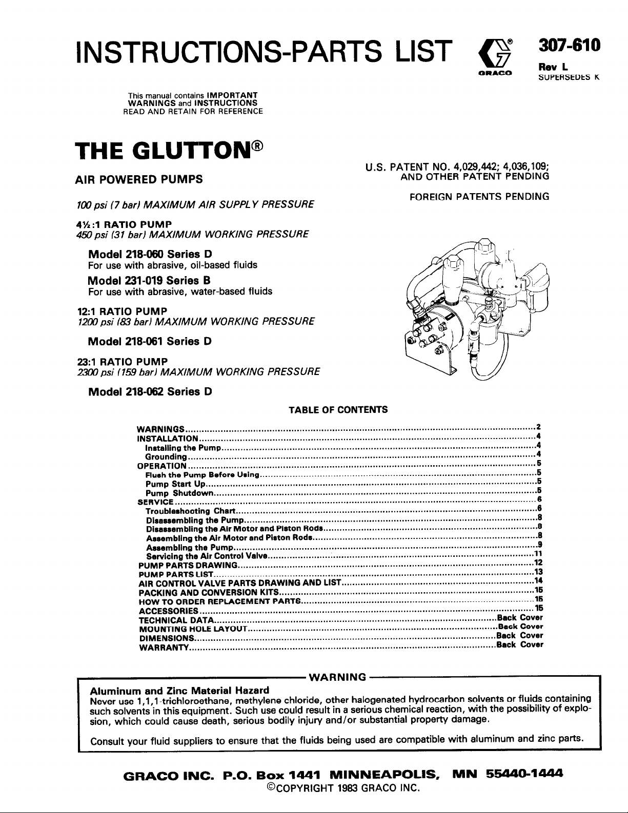
THE GLUTTON@
U.S. PATENT NO. 4,029,442; 4,036,109;
AIR POWERED PUMPS
AND OTHER PATENT PENDING
@ 307-610
G
ORACO
Rev L
SUPERSEDES K
lay) psi (7 bad MAXIMUM AIR SUPPL Y PRESSURE
4’h:l RATIO PUMP
450 psi (31 bar) MAXIMUM WORKING PRESSURE
Model 218490 Series D
For use with abrasive, oil-based fluids
Model 231-019 Series B
For use with abrasive, water-based fluids
12:l RATIO PUMP
1200 psi (83 bar) MAXIMUM WORKING PRESSURE
Model 218461 Series D
23:l RATIO PUMP
231x) psi (15.9 bar) MAXIMUM WORKING PRESSURE
Model 218462 Series D
TABLE OF CONTENTS
WARNINGS
INSTALLATION..
Installing the Pump
Grounding
OPERATION
Flush the Pump Before Using
Pump Start Up
Pump
SERVICE
Troubleshooting Chart
Disassembling the Pump
Disassembling the Air Motor and Plston Rods
Assembling the Air Motor and Piston Rods..
Assembling the Pump
Servicing the Air Control Valve..
PUMP PARTS DRAWING..
PUMP PARTS LIST
AIR CONTROL VALVE PARTS DRAWING AND LIST
PACKING AND CONVERSION KITS
HOW TO ORDER REPLACEMENT PARTS
ACCESSORIES
TECHNICAL DATA.. ......................................................................................................
MOUNTING HOLE LAYOUT
DIMENSIONS
WARRANTY
.................................................................................................................................
..........................................................................................................................
....................................................................................................................
................................................................................................................................
................................................................................................................................
..........................................................................................................................
Shutdown..
.....................................................................................................................................
.....................................................................................................................
......................................................................................................................
...........................................................................................................................
...............................................................................................................
.................................................................................................................
......................................................................................................
...............................................................................................................
............................................................................................................ 8
......
..........
......
................................................................................................ 11
...........................................................................................................
..............................................................................................
...................................................................................... 16
............................................................................................ Back Cover
FOREIGN PATENTS PENDING
............................................................................... 6
.......................................................................
Back
Back Cover
Back Cover
.X
12
13
14
16
15
Cover
2
4
4
4
5
5
6
6
6
6
WARNING
Aluminum and Zinc Material Hazard
Never use 1 ,l ,l -trichloroethane, methylene chloride, other halogenated hydrocarbon solvents or fluids containing
such solvents in this equipment. Such use could result in a serious chemical reaction, with the possibility of explosion, which could cause death, serious bodily injury and/or substantial propem/ damage.
Consult your fluid suppliers to ensure that the fluids being used are compatible with aluminum and zinc parts.
GRACO INC. P.O. Box 1441 MINNEAPOLIS, MN 554404444
@COPYRIGHT 1963 GRACO INC.
Page 2
HIGH PRESSURE SPRAY CAN CAUSE SERIOUS INJURY.
FOR PROFESSIONAL USE ONLY. OBSERVE ALL WARNINGS.
Read and understand all instruction manuals before operating equipment.
FLU/D /NJECT/ON HAZARD
WARNING
General Safety
This eauipment aenerates very high fluid pressure. Sprav from
the gun; leaks-or ruptured. components can inject fluid
through your skin and into your body and cause extremely
serious bodily injury, including the need for amputation. Also,
fluid injected or splashed into the eyes or on the skin can
cause serious damage.
NEVER point the spray gun or dispensing valve at anyone or at
any part of the body. NEVER put hand or fingers over the
spray tip or nozzle. NEVER try to “blow back” paint; this is
NOT an air spray system.
ALWAYS have the tip guard in place on the spray gun when
spraying.
ALWAYS follow the Pressure Relief Procedure, below,
before cleaning or removing the spray tip or nozzle or servicing
any system equipment.
NEVER try to stop or deflect leaks with your hand or body.
Be sure the equipment safety devices are operating properly
before each use.
Medical Alert -Airless Spray Wounds
If any fluid appears to penetrate your skin, get
MEDICAL CARE AT ONCE. DO NOT TREAT AS A
SIMPLE CUT. Tell the doctor exactly what fluid was injected.
Note to Physician:
jury. It is important to treat the injury surgically as soon
as
possible. Do not delay treatment to research toxicity.
Toxicity is a concern with some exotic coatings injected
directly into the blood stream. Consultation with a plastic
surgeon or reconstructive hand surgeon may be advisable.
Pressure Relief Procedure
To reduce the risk of serious bodilv iniury, includinq fluid iniection, splashing in the eyes or on the skin, or injury from moving parts, always follow this procedure whenever you shut off
the pump, when checking or servicing any part of the spray
system, when installing, cleaning or changing spray tips or
nozzles, and whenever you stop spraying.
Engage the gun safety latch.
::
Shut off the air to the motor.
Close the bleed-type master air valve (required).
::
Disengage the gun safety latch.
5.
Hold a metal part of the gun firmly to the side of a grounded metal pail and trigger the gun to relieve pressure.
Engage the gun safety latch.
7:
Open the drain valve (required) and/or the pump bleeder
valve, having a container ready to catch the drainage.
Leave the drain valve open until you are ready to spray
8.
again.
If you suspect that the spray tip/nozzle or hose is completely
clogged, or that pressure has not been fully relieved after
following the steps above, VERY SLOWLY loosen the retain-
ing nut or hose end coupling and relieve pressure gradually,
then loosen completely. Now clear the tip or hose obstruction.
Injection in the skin is a traumatic in-
EMERGENCY
Spray Gun and Dispensing Valve Safety Devices
Be sure all gun or dispensing valve safety devices are
operating properly before each use. Do not remove or modify
any part of the gun or dispensing valve; this can cause a
malfunction and result in serious bodily injury.
Safety Latch
Whenever you stop spraying, even for a moment, always set
the oun or dispensina valve safetv latch in the closed or “safe”
po&on, making the gun or dispensing valve inoperative.
Failure to set the safety latch can result in accidental triggering
of the gun or dispensing valve.
Diffuser /only on spray guns)
The gun diffuser breaks up spray and reduces the risk of fluid
injection when the tip is not installed. Check the diffuser
operation regularly. Follow the Pressure Relief Procedure,
at the left, then remove the spray tip. Aim the gun into a
grounded metal pail, holding the gun firmly to the pail. Using
the lowest possible pressure, trigger the gun. If the fluid emit-
ted is not diffused into an irregular stream, replace the diffuser
immediately.
Tip Guard (only on spray guns)
ALWAYS have the tip guard in place on the spray gun while
spraying. The tip guard alerts you to the fluid injection hazard
and helps reduce, but does not prevent, the risk of accidental-
ly placing your fingers or any part of your body close to the
spray tip.
Trigger Guard (only on spray guns)
NEVER operate the gun with the trigger guard removed. The
trigger guard reduces the risk of accidentally triggering the
gun if it is dropped or bumped.
Spray Tip and Nozzle Safety
Use extreme caution when cleaning or changing spray tips or
nozzles. If the sorav tip or nozzle clogs while spraying, engage
the gun or dispensing valve safety latc‘h immediately.
ALWAYS follow the Pressure Relief Procedure, at the left,
and then-remove the spray tip or nozzle to clean it.
NEVER wipe off build-up around the spray tip or nozzle until
pressure is fully relieved and the gun or dispensing valve safety
latch is engaged.
MOVlNG PARTS HAZARD
Moving parts can pinch or amputate your fingers or other
body parts. KEEP CLEAR of moving parts when starting or
operating the pump. Follow the Pressure Relief Procedure,
at the left, before checking or servicing the pump to prevent it
from starting accidentally. NEVER operate the motor with the
pump housing removed.
SUCTlON HAZARD
NEVER place your hands on or near the pump suction inlet.
Powerful suction could cause serious bodily injury.
7
SO7-610
Page 3
EQUIPMENT MISUSE HAZARD
General Safety
Any misuse of the spray equipment or accessories, such as
overpressurizing, modifying parts, using incompatible fluids,
or using worn or damaged parts, can cause them to rupture
and result in fluid injection or other serious bodily injury, fire,
explosion or property damage.
NEVER alter or modify any part of this equipment; doing so
could cause it to malfunction.
CHECK all spray equipment regularly and repair or replace
worn or damaged parts immediately.
Read and follow the fluid and solvent manufacturer’s recommendations for use of protective clothing and equipment.
System Pressure
The 4-l/2:1 ratio pump can develop 450 psi (31 bar) MAX-
IMUM WORKING PRESSUREat 100 psi (7 bar) maximum incoming air pressure.
The 12:l ratio pump can develop 7200 psi (83 bar) MAXIMUM WORKING PRESSURE at 100 psi (7 bar) maximum incoming air pressure.
The 23:l ratio pump can develop 2300 psi (15.9 bar) MAXIMUM WORKING PRESSUREat 100 psi (7 bar) maximum incoming air pressure.
Be sure that all spray equipment and accessories are rated to
withstand the maximum working pressure of this pump. DO
NOT exceed the maximum working pressure of any component or accessory used in the system.
Fluid Compatibility
BE SURE that all fluids and solvents used are chemically com-
patible with the wetted parts shown in the TECHNICAL DATA
on the back cover. Always read the fluid manufacturer’s
literature before using them in this pump.
HOSE SAFETY
High pressure fluid in the hoses can be very dangerous. If the
hose develops a leak, split or rupture due to any kind of wear,
damage or misuse, the high pressure spray emitted from it can
cause a fluid injection injury or other serious bodily injury or
property damage.
ALL FLUID HOSES MUST HAVE SPRING GUARDS ON
BOTH ENDS! The sorina auards helo orotect the hose from
kinks or bends at or &OS; 6 the cou&g which can result in
hose rupture.
TIGHTEN all fluid connections securely before each use. High
pressure fluid can dislodge a loose coupling or allow high
pressure spray to be emitted from the coupling.
NEVER use a damaged hose. Before each use, check the entire hose for cuts, leaks, abrasion, bulging cover, or damage or
movement of the hose couplings. If any of these conditions
exist, replace the hose immediately. DO NOT try to recouple
high pressure hose or mend it with tape or any other device. A
repaired hose cannot contain the high pressure fluid.
HANDLE AND ROUTE HOSES CAREFULLY. Do not pull on
the hoses to move the equipment. Do not use fluids which are
not compatible with the inner tube and cover of the hose. DO
NOT expose Grace hose to temperatures above 1WF W°C)
or below -40°F (-4O“C).
Hose Grounding Continuity
Proper hose grounding continuity is essential to maintaining a
grounded spray system. Check the electrical resistance of your
air and fluid hoses at least once a week. If your hose does not
have a tag on it which specifies the maximum electrical
resistance, contact the hose supplier or manufacturer for the
maximum resistance limits. Use a resistance meter in the ap-
propriate range for your hose to check the resistance. If the
resistance exceeds the recommended limits, replace it im-
mediately. An ungrounded or poorly grounded hose can make
your system hazardous. Also, read FIRE OR EXPLOSION
HAZARD, below.
F/f?E OR EXPLOSION HAZARD
Static electricity is created by the flow of fluid through the
pump and hose. If every part of the spray equipment is not
properly grounded, sparking may occur, and the system may
become hazardous. Sparking may also occur when plugging
in or unplugging a power supply cord. Sparks can ignite fumes
from solvents and the fluid being sprayed, dust particles and
other flammable substances, whether you are spraying indoors or outdoors, and can cause a fire or explosion and
serious bodily injury and property damage. Do not plug in or
unplug any power supply cords in the spray area when there is
any chance of igniting fumes still in the air.
If you experience any static sparking or even a slight shock
while using this equipment, STOP SPRAYING IMME-
DIATELY. Check the entire system for proper grounding. Do
not use the system again until the problem has been identified
and corrected.
Grounding
To reduce the risk of static soarkina, nround the Dump and all
other spray equipment used or l&%ed in the’ spray area.
CHECK your local electrical code for detailed grounding instructions for your area and type of equipment. BE SURE to
ground all of this spray equipment:
1. Pump: by connecting a ground wire and clamp to a true
earth ground. See the procedure on page 4.
2. Air and fluid hoses: use only grounded hoses with a maximum of 500 feet (150 m) combined hose lenath to ensure grounding continuity. Refer to Hose Giounding
Continuity, above.
3.
Spray gun: obtain grounding through the connection to a
properly grounded fluid hose and pump.
4.
Air compressor: according to the manufacturer’s recommendations.
5.
Fluid supply container: according to the local code.
6.
Object being sprayed: according to the local code.
7.
All solvent pails used when flushing: according to the
local code. Use only metalpails which are conductive. Do
not place the pail on a nonconductive surface, such as
paper or cardboard,
continuity.
To maintain grounding continuity when flushing or reiiev-
8.
ingpressure, always hold a metal part of the gun firmly to
the side of a grounded metal pail, then trigger the gun.
Flushing Safety
Before flushina, be sure the entire system and flushina pails
are properly giounded. Refer to Grounding, to the ‘left.
Follow the Pressure Relief Procedure on oaoe 2. and
remove the spray tip from the gun. Always use ihe lbwest
possible fluid pressure, and maintain firm metal-to-metal contact between the gun and a grounded metal pail during
flushing to reduce the risk of fluid injection injury, static sparking and splashing.
which interrupts grounding
IMPORTANT
United States Government safety standards have been adopted under the Occupational Safety and Health Act. These standards-particularly the General Standards, Part 1910, and the Construction Standards, Part 1926-should be consulted.
307-610
3
Page 4
NOTES:
1. Reference numbers and letters in parentheses in the
text refer to the figure illustrations and the Parts
Drawings.
2. Dimensions, port sizes, and technical data are on
the back page.
3. Accessories are shown on page 15.
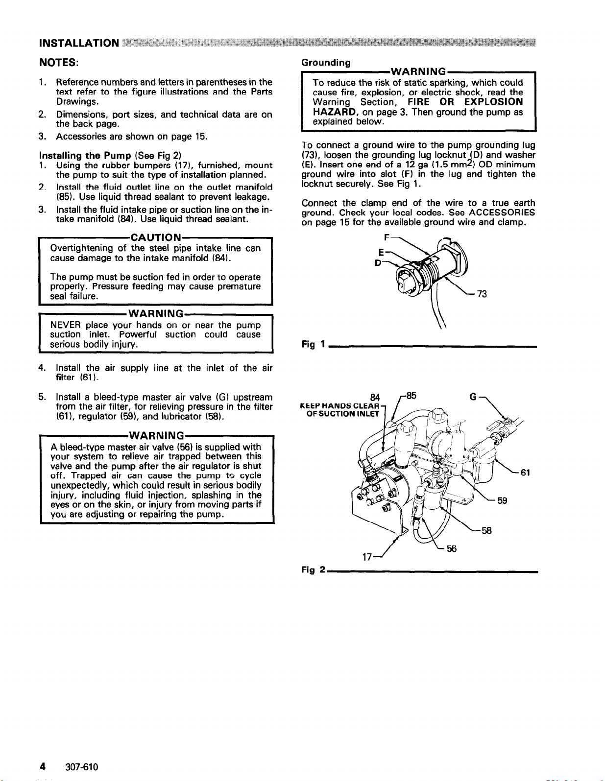
Installing the Pump (See Fig 2)
1. Using the rubber bumpers (171, furnished, mount
the pump to suit the type of installation planned.
2. Install the fluid outlet line on the outlet manifold
(85). Use liquid thread sealant to prevent leakage.
3. Install the fluid intake pipe or suction line on the in-
take manifold (64). Use liquid thread sealant.
Overtightening of the steel pipe intake line can
cause damage to the intake manifold (64).
The pump must be suction fed in order to operate
properly. Pressure feeding may cause premature
WARNING
NEVER place your hands on or near the pump
suction inlet. Powerful suction could cause
serious bodily injury.
Grounding
WARNING
of static sparking, which could
cause fire, explosion, or electric shock, read the
Warning Section, FIRE OR EXPLOSION
HAZARD, on page 3. Then ground the pump as
explained below.
To connect a ground wire to the pump grounding lug
(731, loosen the grounding lug locknut (D) and washer
(El. Insert one end of a 12 ga (1.5 mm21 OD minimum
ground wire into slot (F) in the lug and tighten the
locknut securely. See Fig 1.
Connect the clamp end of the wire to a true earth
ground. Check your local codes. See ACCESSORIES
on page 15 for the available ground wire and clamp.
Fig 1
4. Install the air supply line at the inlet of the air
filter (61).
5. Install a bleed-type master air valve (G) upstream
from the air filter, for relieving pressure in the filter
(611, regulator (591, and lubricator (56).
WARNING
A bleed-type master air valve (56) is supplied with
your system to relieve air trapped between this
valve and the pump after the air regulator is shut
off. Trapped air can cause the pump to cycle
unexpectedly, which could result in serious bodily
injury, including fluid injection, splashing in the
eyes or on the skin, or injury from moving parts if
you are adjusting or repairing the pump.
84 1-85 G-i
Fig 2
4
307-610
Page 5
WAHNINb
Pressure Relief Procedure
To reduce the risk of serious bodily injury, including fluid injection, splashing in the eyes or on
the skin, or injury from moving parts, always
follow this procedure whenever you
shut off
the
pump, when checking or servicing any part of the
spray system, when installing, cleaning or changing spray, tips or nozzles, and whenever you stop
spraying.
1. Engage the gun safety latch.
2. Shut
off the air to the motor.
3. Close the bleed-type master air valve
(required).
4. Disengage the gun safety latch.
5. Hold a metal part of the gun firmly to the side of
a grounded metal pail and trigger the gun to
relieve pressure.
6. Engage the gun safety latch.
7. Open the drain valve (required) and/or the
pump bleeder valve, having a container ready
to catch the drainage.
8. Leave the drain valve open until you are ready
to spray again.
If you suspect that the spray tip/nozzle or hose is
completely clogged, or that pressure has not been
fully relieved after following the steps above,
VERY SLOWLY loosen the retaining nut or hose
end coupling and relieve pressure gradually, then
loosen completely, Now clear the tip or hose
obstruction.
Flush the Pump Before Using
The pumps are tested with hydraulic oil, which is left in
to protect the pump parts. Read and follow Flushing
Safety under FIRE OR EXPLOSION HAZARD
on
page 3. Then flush the pump with a compatible solvent.
If the pump is being used in a circulating system, allow
the solvent to circulate long enough to thoroughly flush
the pump and the fluid lines.
Puma Start Up
1.
check and- service the lubricator, regulator, and
filter according to the instructions supplied with
them.
Open the bleed-type master air valves.
2.
Open the air regulator slowly. Adjust it until the
3.
pump runs smoothly.
4.
If you are using this pump to spray fluid, trigger the
gun to prime the hose. Adjust the pump pressure
just enough to completely atomize the fluid. Higher
pressures cause premature spray tip and pump
wear.
5.
Never allow the pump to run dry of the fluid being
pumped. A dry pump will quickly accelerate to a
high speed, possibly damaging itself. If your pump
accelerates quickly, or is running too fast, stop it
immediately and check the fluid supply. If the supply container is empty and air has been pumped into the lines, refill the container and prime the pump
and lines with the fluid, or flush and leave filled with
a compatible solvent. Be sure to eliminate all air
from the fluid system.
Pump Shutdown
1.
Close the bleed-type master air valves.
2.
If you are using a gun or a dispensing valve, relieve
the system pressure by following the Pressure
Relief Procedure Warning at the left. If you are
not using a gun or a dispensing valve, relieve the
system pressure by opening the fluid outlet valve.
3.
Always flush the pump before the fluid dries in it.
Read and follow Flushing Safety under FIRE OR
EXPLOSION HAZARD on page 3. If the pump is
to be stored for any period of time, and you are
pumping water-based fluid, first, flush the pump
with water and then with mineral spirits or a com-
patible solvent to protect the pump parts. Leave the
mineral spirits or an oil-based solvent in the pump
to prevent corrosion.
307-610 5
Page 6

To reduce the risk of serious bodily injury, ineluding fluid injection, splashing in the eyes or on
the skin, or injury from moving parts, always
follow this procedure whenever you shut off the
pump, when checking or servicing any part of the
spray system, when installing, cleaning or changing spray tips or nozzles, and whenever you stop
spraying.
1. Engage the gun safety latch.
2. Shut off the air to the motor.
3. Close the bleed-type master air valve
(required).
4. Disengage the gun safety latch.
5. Hold a metal part of the gun firmly to the side of
a grounded metal pail and trigger the gun to
relieve pressure.
6. Engage the gun safety latch.
7. Open the drain valve (required) and/or the
pump bleeder valve, having a container ready
to catch the drainage.
8. Leave the drain valve open until you are ready
to spray again.
if you suspect that the spray tip/nozzle or hose is
completely clogged, or
fully relieved after following the steps above,
that
pressure has not been
VERY SLOWLY loosen the retaining nut or hose
end coupling and relieve the pressure gradually,
then loosen completely. Now clear the tip or hose
obstruction.
SYMPTOM
1. Pump will not
prime
2. Pump will not run
PROBABLE CAUSE TEST PROCEDURE REMEDY
Air is getting into the intake
housing:
a) Porous accumulator or poor
seal on the accumulator accumulator
threads
b) Defective o-ring on intake
manifold
cl Intake manifold not sealed
a) Tighten or replace
b) Replace o-ring
c) Tighten or add sealant to
threads of intake manifold;
replace intake
necessary
a)
Air supply turned off
b) Fluid valve turned off b)
c) Air pressure regulator set
too low
c) Minimum air pressure on
regulator 35 psi (2.4 bar)
(depending on fluid being
a) Turn air supply on
Turn fluid supply valve on
c) Increase air pressure
regulator adjustment
pumped I
e) Pilot valve assemblies (41
worn
e) Remove tube ends (18 Et 88) e) Replace pilot valve
from hose studs We); with assembly (4)
air supply on, alternately
plug tube ends; if pump
runs, remove pilot valves
and inspect
manifold if
6
307-610
f) Air control valve (531
defective
g) Air piston seal (2) worn
h) Air control valve spool h1 Check for exhaust at
g) Check for air coming
from exhaust when pump is seal (2)
not running
centered in valve block both mufflers at same time
f) Repair or replace air
control valve 63)
g) Replace air piston
hl Remove one muffler and
momentarily cover hole
Page 7

TROUBLESHOOTING CHART ‘: T il’ ’
:
SYMPTOM
L Pump runs but
does not maintain
constant pressure
PROBABLE CAUSE
a) Air in fluid line a) Check for spitting at
b) Dirty or worn check valve
assemblies (Items 12, 26, 27, continues to run, check seat (391, ball (261, spring
33, 39, Et 971
c) Pilot valve assemblies (4) c) Remove tube ends (18 Et 96) c)
worn
d) Worn piston (40) and/or
piston seal (24)
f) Air control valve mufflers
(78) plugged
g) Air control valve (53)
dirty or worn
h) Lack of lubrication
Dirty air passages
il
TEST PROCEDURE
fluid line outlet
b) Shut off fluid valve; if pump b)
valve may be dirty or worn (271, and ball guide (97);
from hose studs Me); with assembly (4)
air supply on, alternately
plug tube ends; if pump
keeps running, remove and
inspect pilot valve
assemblies
d) Shut off fluid valve; if pump d)
keeps running, piston MO)
and/or seal (24) may be
worn
f) Check for slow air flow
at mufflers (78) mufflers (78)
h) Pump reacts slowly h) Adjust lubricator
Check for sluggish air con-
il
trol valve operation
REMEDY
a) Bleed fluid line until
constant flow is obtained
Remove, clean, and inspect
replace if worn
Replace pilot valve
Replace piston and/or
seal (24)
f) Remove and clean
g) Repair or replace air
control valve (63)
il Clean air passages; (do not
enlarge orifices); empty air
line filter
1. Pump continues to a) Dirty or worn check
run with fluid valve assemblies (Items
supply valve shut
Off
i.
Paint dripping from a)
drain slot on
external side of air
motor
12, 26, 27,
b) Worn piston (40) and/or
piston seal (241
Ruptured bellows seal (8)
33, 39, Et 971
a) Shut off fluid valve; if
pump continues to run, inspect seat (391, ball
check valves may be worn
or dirty
b) Same as above
a) Check for presence
of paint on outside
of air motor
a) Remove, clean, and
126), spring (27), and ball
guide (97); replace if worn
b) Replace piston MO1
and/or piston seal (241
a) Replace bellows seal (8)
NOTE: Pressure feeding the
pump may damage bellows
seal. Be sure to suction feet
the pump.
307-610 7
Page 8

Disassembling the Pump
cluding fluid injection, splashing in the eyes or on
the skin, or injury from moving parts, ALWAYS
follow the Pressure Relief Procedure Warning
on page 6 before servicing the pump.
NOTES:
If you are using a repair kit to service the
pump, use all the new parts, even if the old
ones look good. Old parts do not seal well
with new ones, and the pump may leak.
WARNING
Certain steps in the disassembly procedure require
the use of low pressure air injected into the air
motor intake ports to move the pistons (fluid and
air) from one end of their stroke to the other.
To reduce the risk of serious bodily injury, including amputation, keep your hands clear of all
moving parts while moving the pistons with low
pressure air.
?fer to the Parts Drawing on page 12.
1. Relieve system pressure by following the Pressure
Relief Procedure Warning on page 6.
2. Disconnect the air and fluid lines, remove the pump
from its mounting and place it on a bench.
3. Loosen the two nuts on each side of the outlet
manifold (85) and remove it.
4. Remove the intake manifold (84) by removing the
nuts
(89) and washers (88) from each manifold
flange (81). Remove the screws (87).
5. Remove the four hex head bolts (50) and
lockwashers, the check valve housing (30), ball
guide (97), ball stop (33), spring (27), ball (26), seat
(39), and o-ring (12) from one end of the pump.
6. Remove two hex nuts (45) and lockwashers and the
support bracket (28). Remove the two remaining
hex nuts, lockwashers, and the pump housing (25).
7. Repeat steps 5 and 6 working on the opposite end
of the pump.
8. Remove the tube ends (18 & 96) from the hose
studs (4e) on each end of the air motor.
9. Disconnect the hose (55) from the air control
valve (53).
10. Position the pump to gain access to the air control
valve (53), located on the bottom of the pump.
Remove the four socket head machine screws (52),
and remove the air control valve from the pump.
11. Use an air blow gun to apply low pressure air f25 psi
(1.75 bar) maximum] to one of the air motor intake
ports (located at the air control valve mounting) to
move one of the pistons (40) to the full “in” position.
NOTE:
For ease of assembly, the accumulator (37)
and the intake fitting (83) should never be
removed from the pump housing (22) unless
specific repairs to the accumulator or the
pump housing are required.
13. Repeat steps 11 and 12, working on the opposite
end of the pump.
14. Remove the piston hex head bolt (44) using a
socket head breaker bar.
breaker bar using a soft mallet
Apply a sharp blow to the
to loosen the hex
bolt. Be sure you loosen the hex bolt and not the
piston stud (47).
15. Remove the piston (40) by grasping it with your
hands and pulling with a rocking motion to free it
from the piston rod.
16. Remove the bellows seal (8), [with the intake plate
(21). Models 218-060, 231-019 and 218-061 only].
Then remove the centering ring (36).
17. Repeat steps 14-16 working on the opposite end of
the pump.
Disassembling the Air Motor and Piston Rods
To remove the piston rods, the air motor must be
disassembled:
1. Remove two machine screws (43) and the pilot
valve assembly (4), from each end of the air motor.
2. If replacing the valve stem (4i) and rod seal (4h),
remove the stem from the air motor plate. Use the
end of the valve stem to pry the seal out of the air
motor plate. Do the same on the other end of the air
motor.
3. Remove the four hex head bolts (41) and the lockwashers. Remove the mounting bracket (34) with
the filter/lubricator/regulator assembly (55-62).
Remove the sixteen remaining hex bolts (41) and
both air motor plates (19, 20).
4. Remove the air motor piston (10) with the piston
rods (11) from the air motor by pushing the piston
out through the motor ring (16).
5. Using the packing nut wrench (179901, see ACCESSORIES on page 15). remove the bearing (91)
and the u-cup packing (90) from each air motor
plate (19, 20).
6. With the wrenches on the flats of the piston rods
(1 1), unscrew and disconnect the piston rods from
the air motor piston (IO) and piston stud (47).
NOTE:
DO NOT disassemble the piston rods unless
replacement is needed, as a high strength
adhesive thread sealant was used on the
threads. Heating the joint to 3OOOF will ease
disassembly if removal is necessary.
12. Working on one end of the pump with the piston at
the full “in” position, remove the piston seal (24),
piston guide (23), and the pump housing (22).
R
2n7-610
Assembling the Air Motor and Piston Rods
NOTE:
Lubricate all the packings, seals, and mating
surfaces with lithium base grease before
assembling, except the piston seal (24).
Page 9

1. Apply high strength adhesive thread sealant to the
IcAyT’oNl
piston stud (47). Partially thread one piston rod (11)
onto the piston stud.
Over-tightening of the piston rods (11) can shear
IIheAIfudT’ON -1
NOTE:
2. Install the o-ring (1) on the outside face of the air
3. Install the u-cup packing (901, lips down, into the
4. Install the valve stem (4i) and rod seal (4h) in the
5. Turn the motor ring/motor plate assembly over and
6. Insert the piston rod/piston stud assembly
7. Generously coat the inside of the air motor ring (16)
8. Install the u-cup packing (90), lips down, into the
9. Install the o-ring (1) on the outside face of the
10. Slide the left motor plate (20) onto the piston rod
11. Install the valve stem (4i) and rod seal (4h), with the
NOTE:
The piston stud threads should extend into
the piston rod about 5/16 in. (7.93 mm).
motor ring (16). Place the right motor plate (19) on
the face of the motor ring. Align the motor plate
with the motor ring by aligning the machined flats
on the outside diameter of both pieces. Install eight
hex bolts (411, with lockwashers, in the motor plate
and tighten until snug. Alternately and progressively, tighten the hex bolts and torque to lo-20 ft-lb
(13.5-27.0 N-m).
motor plate (19). Screw in the bearing (911, using
the packing nut wrench (179901, see AC-
CESSORIES). Torque the bearing to lo-20 ft-lb
(13.5-27 N.m).
motor plate (19). Then install the pilot valve
assembly (4) on the motor plate, using the two
machine screws (43).
set it on blocks.
(assembled in step 1) through the hole in the air
motor piston (10). Apply high strength adhesive
thread sealant to the exposed threads of the piston
stud (47). Then thread the other piston rod (11) onto the piston stud and hand tighten. Install the
quad-ring (2) in the groove of the air motor piston.
and the quad-ring (2) on the air motor piston (10)
with lithium base grease. Lower the piston rod/air
piston assembly (assembled in step 6) into the air
motor ring (16) until the piston rests on the motor
ring.
Using a soft mallet, lightly
of the air motor piston until it enters the motor ring.
motor plate (20). Screw in the bearing (911, using
the packing nut wrench, 179901. Torque the bear-
ing to lo-20 ft-lb (13.5-27 N.m).
motor ring (16). Apply lithium base grease to the in-
side of the motor ring where the piston (10) has
scraped the ring clear of grease during installation.
(11) and the motor ring (16). Align the motor plate
with the motor ring by aligning the machined flats
on the outside diameter of both pieces. Install eight
hex bolts (41) with lockwashers in the motor plate
and tighten until snug. Alternately and progressively, tighten eight hex bolts and torque to lo-20 ft-lb
(13.5-27.0 N-m). (The four remaining hex bolts are
used to mount the filter/lubricator/regulator
assembly in step 13.1
sealing lips down, in the motor plate (20). Then in-
stall the pilot valve assembly (4) on the motor plate,
using the two machine screws (43).
When installing the trigger valve assembly,
be sure the hose studs Me) in the housing
(4c) face away from the front of the pump to
ease tube connection.
tap around the top
13. Install the filter/lubricator/regulator assembly using
the four remaining hex bolts (41) with lockwashers.
Torque to lo-20 ft-lb (13.5-27.0 N-m). Connect the
hose (55) to the air control valve (53).
14. Connect the tubes (96) between each pilot valve’s
inlet hose stud (4e) (the hose stud farthest from the
air motor) and a manifold hose stud (95).
Assembling the Pump
1. Using an air blow gun, slowly apply low pressure air
125 psi (1.75 bar) maximum] to one of the air motor
intake ports, located on the machined flats of the
motor plates (19,201, to move either piston rod (11)
to the full “out” position.
To reduce the risk of serious bodily injury, in-
NOTE:
2. Install the centering ring (36) down along the piston
3. Coat the inside of the bellows seal (8) with lithium
DO NOT force the small end of the bellows seal (8)
onto the piston rod (11) or damage to bellows will
occur. lnstallrng the piston (40) will clamp the
bellows seal onto the piston rod.
4. Models 218-090, 231-019, 218-081 only. Place the
5. Without forcing, place the piston (40) on top of the
6. Repeat steps l-5, working on the opposite end of
7. Using a socket and breaker bar on each piston bolt
Over-tightening of the piston bolts (44) can shear
(7PiTfOn.fYd(47;AUT’oN -1
Working on the end of the air motor with the
piston rod (1 I) in the full “out” position,
complete steps 2-5.
rod (11) and onto the motor plate so that the
grooves in the face of the ring are toward the air
motor.
base grease, and place it onto the piston rod so that
the large flange of the seal faces toward the motor.
intake plate (21) over the piston rod (11) and the
bellows seal (8) so the large flange of the seal enters
the counterbore in the intake plate. Do not force
the intake plate down onto the motor plate.
bellows seal (8) and the piston rod (11). Insert the
piston bolt (44) through the piston and thread it into
the piston rod. Tighten only until snug.
the pump.
(441, torque one piston bolt to 40-50 ft-lb
(54-68 N*m). Then reverse the procedure and tor-
que the other piston bolt in the same way.
J
12. With a wrench on the flat of each piston rod (111,
apply opposing force and tighten the piston rods
until snug.
307-610 9
Page 10

8. Using an air blow gun, slowly apply low pressure air
[25 psi (1.75 bar) maximum] to one of the air motor
intake ports [located on the machined flats of the
motor plates (19, 2011, moving either piston (40) to
the full “in” position.
To reduce the risk of serious bodily injury, in-
NOTE:
9. Models 218480, 231-019, 218081 only.
NOTE:
10. Model 218-080, 231-019 only.
Working on the end of the pump with the
piston (40) at the full “in” position, complete
steps 9 and 10.
Install the face seal (29) with the flat side against
the back of the shoulder of the intake plate (21).
Then install the pump housing (22) so the seal and
the intake plate seat in the shallow counterbore of
the pump housing.
Model 218482 only
Install the pump housing (22) over the bellows seal
(8) and the piston (40) and onto the motor plate so
the counterbore in the pump housing faces in
toward the air motor.
DO NOT use grease when installing the piston seal (24) because the seal may pull out of
the counterbore of the housing.
Install the o-ring 198) on the pump housing (22). In-
stall the piston guide (23) onto the alignment studs
(38) and up against the pump housing (22) so the
larger beveled opening of the piston guide faces in
toward the air motor. Install the piston seal (24) in
the shallow counterbore of the pump housing (25).
While holding the piston seal in place, slide the
pump housing with the seal onto the alignment
studs and up against the piston guide. Install the
support bracket (28) on the alignment studs. Install
the four hex nuts (45) with lockwashers. Alternately
and progressively, tighten the hex nuts and torque
them to 20-30 ft-lb (27-40 N.m).
Model 218-081 only.
Install the o-ring (98) on the shoulder of the piston
guide (23). Install the guide on the pump housing
(22) so the o-ring faces in toward the housing. Install the piston seal (24) in the shallow counterbore
of the pump housing (25). While holding the seal in
place, slide the pump housing onto the alignment
studs (38) and up against the pump housing. Install
the support bracket (28) and the hex nuts (45) with
lockwashers onto the alignment studs. Alternately
and progressively, tighten the hex nuts and torque
them to 20-30 ft-lb (27-40 N-m).
NOTE:
When repeating steps 8-10 on the opposite end of
11. Working on one end of the pump, install the check
NOTES:
12.
13.
14.
15.
16.
Repeat steps 8-10, working on the opposite
end of the pump.
valve seat (39) in the pump housing (25) so the
flange of the seat (39) faces
the pump. Place the o-ring (12) around the seat and
onto the pump housing. Install the spring (271, ball
stop (331, and ball guide (97) in the check valve
housing (30). Align the slot in the ball guide with
the pin in the check valve housing. Standing the
pump on end, place the ball (26) on the seat. Install
the check valve housing, with the spring and the
ball stop, onto the housing, using the hex nuts (50)
and lockwashers.
1. Do not completely tighten the bolts (50)
at this time.
2. Repeat step 11, working on the opposite
end of the pump.
Install the o-ring (82) in the groove in the intake fitting (831. Install the intake manifold (84) by inserting the screws (87) into the flanged ends of the
manifold. Insert the washers (88) and the nuts (89).
Fit the outlet manifold (85) into the connectors (86)
and tighten the nuts. Alternately and progressively,
tighten the bolts (50) on the check valve housings
(30) and torque them to lo-20 ft-lb (13.5-U N.m).
Position the pump to gain access to the air control
valve mounting location on the bottom of the
pump. Using the four socket machine screws (521,
install the air control valve (53). Alternately and progressively, tighten the machine screws. Torque/
them to 35-45 in-lbs (3.9-5.1 N-m).
Connect each
outlet hose stud Me) (the hose stud closest to the
air motor) and the control valve’s elbow (115). The
tube from the right side pilot valve must connect to
the left side elbow (115) and the tube from the left
side pilot valve must connect to the right side elbow
(the two tubes will cross each other). See Fig 3. If
the tubes are not connected to the correct side
of the control valve, the pump will not cycle.
Be sure to reconnect the ground wire before
operating the pump.
tube
(18) between the pilot valve’s
TOP VIEW
out
toward the end of
n
Model 218482 only.
Install the piston seal (241 into the counterbore of
the pump housing (25). Install the o-ring (99)
around the outside (not on the shoulder) of the
piston guide (23). Install the guide into the counter-
bore of the pump housing so the larger beveled
opening of the guide faces away from the pump
housing. Slide the pump housing with the guide
and the seal onto the alignment studs (38) and up
against the pump housing (221. Install the support
bracket (28) and the hex nuts (45) with the
lockwashers (46) on the alignment studs (38). Alter-
nately and progressively, tighten the hex nuts and
torque them to 20-30 ft-lb (27-40 N-m).
10
307-610
18
Fig
Page 11

Servicing The Air Control Valve
Refer to Parts Drawings on pages 12 and 14.
1.
Remove the tube ends (18) from the two end block
elbows (115).
2.
Remove four socket head machine screws (101)
and the end block (114) with the elbow (115) and
the muffler (78). Repeat the procedure on the op-
posite end of the air control valve.
With the valve spools (106) centered in the block
3.
(1101, apply opposing force with the wrenches on
the dalve spool flats, and unscrew the valve spools
from the spool stem (107). Remove the spools and
the stem from the center block.
4.
Unscrew the mufflers (78) and the lock rings (79)
from the end blocks (114).
Unscrew and remove the elbows (115) from the end
5.
blocks (114).
NOTE:
Apply lithium grease to all o-rings before
assembling and to the complete spool
assembly before installing it into the center
block (110).
6. Install the new o-rings (105,109,lll) on each spool
(106). Be sure the o-rings are seated properly in the
grooves.
9. Install a gasket (103) into each end block (114) and
then install an o-ring (104) on the shoulder of each
end block (114).
10. Install the end blocks (114) onto the center block
(110) using the socket head machine screws (101).
Torque the screws to 35-45 in-lbs (3.9-5.1 N-m).
11. Install the mufflers with the lock rings into the end
blocks.
CAUTION
Mufflers must be installed with the lock rings.
Failure to do so may result in damage to the spool
and the o-rings during operation.
12.
Install end block elbows (115) in the end blocks
(114).
13.
Connect the tubes (18) as instructed on page 10,
step 15.
14.
Install the o-rings (105) in the top of the center
block (110). Install the air control valve on the
pump. Torque the air valve mounting screws, alternately and progressively, to 35-45 in-lbs
(3.9-5.: N-m).
NOTE: O-ring (105) has an ID of 0.612 in. and
o-ring (109) has an ID of 0.549 in. Do not
switch them; the pump will not run.
7. Apply low strength adhesive thread sealant to only
the tips of the spool stem (107). Remove the excess
sealant.
8. Thread one spool (106) onto the stem (1071 and in-
sert it in the center block (1101. Then thread the
other spool (106) onto the stem (107). Apply opposing force with wrenches on the flats of the spools
(106) and tighten until snug.
307-610 11
Page 12

is
3
4
0
NOTE: Apply sealant to all nonswiveling npt threads.
87
\
TORQUE TO
4MO ft-lb
(52-82 N.m)
ALTERNATE
PROGRESSI’
TOM
‘$-bTo
10-20
1 :13.5-27 N.rnI
LYEt
VELY
I”..--- - -
a-30 ft-I b
(27-40 N.m)
I
ALIGN SLOT
IN GUIDE (97)
WITH PIN IN
HOUSING (30)
TsClf Fb’ 0
(3.9-5.1 N.ml
I
Ref. No. 4 Includes items 4a-4i
Ref. No. 21, 29
Models 218-060,
hf.
NO.
53 See Daw
Et 95
231-019
14 for oafls
B
218461
only
Page 13

GLUlTON PUMP
Model 218-080, 231-019, 218-081, Et 218-082
REF PART
NO. NO.
+107-159
:
‘107-160
4
218-956
101-435
2
105-745
181-131
2
108-383
181-138
181-133
:
107-161
4i
181-132
1:
11
l2 r 179-821
16
17
18
19
2
22
23 179-848
24
25 179850
26
z
29
30
E
:
38
39
40
179-815
179-817
179-818
179-845
i
-*157-195
179-846
I-
107-166
181-135
179-823
179-824
179-825
179-826
179-847
179-854
i
179-627
179-855
iI
181-266
* 179-828
*179-849
“179-856
181-267
i
179-829
179-857
-I
181-268
107-167
108-286
i
179830
179831
l
181-313
224-603
179-833
179-834
179-835
179-636
179-837
I
179-858
I- 179438
-I-
220-002
r 179839
-L
179-851
179-858
DESCRIPTION
O-RING; nitrile rubber
QUAD-RING; nitrile rubber
PILOT VALVE ASSY.
(Includes items 4a-4i)
.BALL, valve, pilot
*SPRING, valve
.HOUSING, valve
.STUD, hose
.GASKET; polyethylene
.CAP, valve
.SEAL, rod
.-STEM, valve
SEAL, bellows
PISTON, motor, air
ROD, piston (Models 218-060 &
231-019)
ROD, piston (Models
218-061 Et 218-062)
O-RING; nitrile rubber
RING, motor (Models 218-060 Et
231-019)
RING, motor (Models
218-061 Et 218-062)
BUMPER
TUBE; nylon, 0.225” O.D. x 0.125”
ID, 13” (330 mm) long
PLATE, motor, riaht
PLATE; motor; le’ft
PLATE. intake (Models
218-066, 231-019 & 218-061)
HOUSING, pump (Models 218-060 B
231-019)
HOUSING, pump (Model 218-061)
HOUSING, pump (Model 218-062)
GUIDE, piston (Model 218-060)
GUIDE, piston (Model 218-061)
GUIDE, piston (Model 218-062)
GUIDE, piston (Model 231-019)
SEAL, piston (Model 218-060)
SEAL, piston (Model 218-061)
SEAL, piston (Model 218-062)
SEAL, piston (Model 231-019)
HOUSING, pump (Model 218-060
HOUSING, pump (Model 218061)
HOUSING, pump (Model 218-062)
HOUSING, pump (Model 231-019)
BALL, valve; SST, 1” dia. (Models
218-060. 218-061 Et 218-062)
BALL, valve; tungsten carbide, 1”
dia. (Model 231-019)
SPRING, compression
BRACKET, support
SEAL, face; UHMW polyethylene
(Models 218-060, 231-019 & 218-061)
HOUSING, valve, check
STOP, ball
BRACKET, mounting
RING, centering
ACCUMULATOR
STUD, alignment
(Models 218-060, 231-019 8 218-0611
STUD, alignment (Model 218-062)
SEAT. valve. check (Models 218-060.
218-061 Et 2i8%62)
SEAT, valve, check (Model 231-019)
PISTON, fluid (Models 218-060 Et
231-019)
PISTON, fluid (Model 218-061)
PISTON, fluid (Model 218-062)
REF PART
NO. NO.
45 100-321
46
2
4iJ
50 107-175
E
55 218-093
56
z 214848 100-l 19
ii 206-197 101-180
: 106-149 107-311
66 179-842
72 179-885
73 104-029
75 179-944
77 164-259
598 107-190 107-189
80 156-684
ii 180-766
83 180-767
84- r
100-018
179-840
loo-077
101344
107-176
107-142
“108-103
218-722
218-723
85
L 108-104
86
ii
89
90
ii;
2
96
z
98
100
““Refer to page 14 for Parts List and Parts Drawing.
See “How To Order Replacement Parts” on page 15.
108-105
i
102-269
:g:g
*108-158
* 180-997
104582
181-134
108-383
181-136
181-264
“102-778
“107-179
*107-180
150-287
“Included in Repair Kit. Refer to page 15.
DESCRIPTION
NUT, hex; l/2-13 thd
WASHER. lock: l/2”
STUD, piston
NUT. hex: 5/16-18 thd
SCRiW, mounting; 5/16-18x 318”
BOLT, machine; 3/8-16 x 3”
WASHER
SCREW, machine; lo-24 x 2”
VALVE, control, air
(Models 218-061 Et 218-062)
VALVE, control, air (Models 218-060
Et 231-019)
HOSE, coupled; l/2 npt(m), l/2”
ID, 18” (457 mm) long, buna-N,
Static free
VALVE, ball; l/2-14 npt
ELBOW, street; 90°, l/2 npt
LUBRICATOR, air
REGULATOR, air
GAUGE, pressure
FILTER, air
NIPPLE, hex; l/2” x l-5/8”
LABEL, warning, hhc :
LABEL, warning 1
LUG, grounding
LABEL, warning ;
ELBOW, street;
l/4 nptff) x 3/8 npt(m)
MUFFLER
RING, lock f
ADAPTER, union; l/2 npt(m) x
l/2 npt(f) swivel
FLANGE, manifold :
O-RING; Vito@
FITTING; intake
MANIFOLD, intake (Model 218-061)
MANIFOLD, intake (Models 218-060
8 231-019)
MANIFOLD, intake (Model 218-062) ;
MANIFOLD, outlet (Model 218-062)
MANIFOLD, outlet (Model 218-061)
MANIFOLD, outlet (Models 218-060
& 231-019) 1
CONNECTOR, male; l-1/16-12 thread
(Model 218-062) 2
CONNECTOR, male; l-5/16-12 thread
(Models 218660, 23i-019 Et 218-061)
SCREW. cao hex: 5/16-18x 1.250”
WASHER ’
NUT, heavy hex; 5/16-18 thread 44
U-CUP PACKING; buna-N
BEARING, shaft
WASHER, tab
MANIFOLD; l/2-14 npt
STUD, hose :
TUBE; nylon, 0.225” OD x 0.125” ID,
20” (505 mm) long
GUIDE, ball ;
O-RING; nitrile rubber (Models 218-060
& 231-019)
O-RING; nitrile rubber (Model 218-061)
O-RING; nitrile rubber (Model 218-062)
COUPLING; l/4 npt(m) x 3/8 npt(f)
QTY
4
8
:
1
1
1
:
1
:
1
;
1
1
1
2
4
2
2
1
;
:
ii
44
107-171 103846
107-174
BOLT, machine, hex; 5/16-18x l-1/2”
SCREW, machine; lo-24 x l/2”
BOLT, hex; SST, l/2-20 x l-l /4”
307-610
13
Page 14

AIR CONTROL VALVE
Model 218-083
AIR CONTROL VALVE
Model 218-084
REF PART
NO. NO.
101 107-m
163 ‘181-464
104 l 107-185
105 ‘107-186
:iY 179-862 179-865
109 ‘107-187
110 179-867
111 l 107-188
114 179-864
115 107-163
116 100403
*Supplied in repair kit 2 18-W
See ‘Wow To Order Replacement Parts” on page 15.
DESCRIPTION
SCREW, machine, socket head,
10-24x2-1/2
GASKET; polyurethane
O-RING; nitrile rubber
O-RING; nitrile rubber
SPOOL, differential
STEM, spool
O-RING; nitrile rubber
CENTER BLOCK
O-RING; nitrile rubber
END BLOCK
ELBOW, male, mini barb;
PLUG, pipe; l/8 npt
9oof ‘I8
AIR CONTROL VALVE REPAIR KIT 218-084
Q-I-Y REF
8
2
2 :ii
4
:
1
;
npt :
Ref No.
103
104 ;
105
109
111 s
NO.
107-183
101
“181-464
“107-185
l
107-186
105
179-862
179-866
l
107-187
:: 169
110
179-868
111 114
l 1;EE
107-163
115
100-403
116
*Supplied
See “How To Order Replacement Parts” on page 15.
DESCRIPTION
SCREW, machine, socket head;
10-24x2-1/2
GASKET; polyurethane
O-RING; nitrile rubber
O-RING; nitrile rubber
SPOOL, differential
STEM, spool
O-RING; nitrile rubber
CENTER BLOCK
O-RING: nitrile rubber
END BLOCK
ELBOW male, mini barb; BOO, l/8 npt
PLUG, pipe; l/8 npt
in
repair kit 218-084.
Qw
4
QTY
8
f
4
2
:
:
s
1
Page 15

PACKING REPAIR AND CONVERSION KITS
(Must be purchased separately)
PACKING REPAIR KITS
INCLUDES 2
PUMP KIT
MODEL NO. NO.
following items (see
Parts List, page 13)
218-060 218-085 12, 24, 29, 82, 98
ea.
of
the
PACKING CONVERSION KITS
See Manual 307-736 for parts,
PUMP VITONO
MODEL
NO. KIT NO.
CONVERSION
ETHYLENE-PROPYLENI
CONVERSION KIT NO.
218-061 218-086 12, 24, 29, 82, 98
218-062 218-087 12, 24, 82, 99
231-019 231-021 12, 24, 29, 82, 98
AIR PISTON SEAL REPAIR KIT 218-885
Ref No.
QtY
2
:
1
E 22
VALVE CONVERSION KIT 218-888
For use with Zinc-rich fluids.
Two required. Includes:
Part No.
179-871
157-195
218-146
ACCESSORIES
Description
Spacer
O-ring
Valve Housing
(Must be purchased separately)
QTY
1
:
GROUND WIRE 288-958
(7.6 m) 25 f-t Ig
218-060 231-022 231-023
218-061 231-024
I
I
231-025
218-062 1 231-026 231-027
1 I
231-019 ] 231-022
VALVE SEAT CONVERSION KIT 231-028
For use with corrosrve ~IUICIS sucn as catalyzea var-
. r...
1
231-023
nishes. See Manual 307-736 for parts.
PUMP CONVERSION KIT 228-888
To convert Pump Model 218-060 to an abrasiveresistant pump. See Manual 307-736 for parts.
PILOT VALVE CONVERSION KIT 218959
For converting the Glutton Pump (Models 218-060,
218-061 and 218-062, Series A and B) from the old-style
pilot valve to the new-style pilot valve. See Manual
307-715 for parts.
BLEED-TYPE MASTER AIR VALVE
300 psi (21 barl MAXIMUM WORKING PRESSURE
Relieves air trapped in the air line between the pump air
inlet
and this valve when closed.
107-141 314 npt(m xf) inlet & outlet
107-142 l/2 npt(m x f) inlet & outlet
TOOLS 179-881
Packing Nut Wrench
INLET ADAPTERS
188-144 Bushing l-l /4-l l-l /2 npt(m) x 3/4-14 npt(f)
188-145 Nipple 314-14 npt(m) x l-1/4-11-1/2 npt(f)
HOW TO ORDER REPLACEMENT PARTS
1. To be sure you receive the correct replacement parts,
kit or accessories, always give all of the information
requested in the chart below.
2. Check the parts list to identify the correct part number;
do not use the ref. no. when ordering.
3. Order all parts from your nearest Grace distributor.
6 digit
PART
NUMBER QTY
PART DESCRIPTION
SERVICE INFORMATION
Listed below by the assembly changed are OLD, NEW,
and ADDED parts.
ASSEMBLY PART
CHANGED STATUS
218-060
231-01s
Pumps
All
Pumps
8 OLD
NEW
OLD
NEW
ADDED
\ITERCHANGEABILITY NOTE: NEW parts replace
ILD parts listed directly above them.
REF PART
NO. NO.
102-269 Screw
49 101-344 Screw
165641 Union
77 164-269 Elbow
100 150-267 Coupling
NAME
307-610 15
Page 16

TECHNICAL DATA
Recommended Air Operating Range : 35-100 psi (3-7 bar)
Maximum Recommended Pump Speed : 80 cycles per minute
Vito@ is a registered trademark of the Du Pont Company.
Loctite@ is a registered trademark of the Loctite Corporation.
MOUNTING
HOLE LAYOUT :
Fluid Outlet : 1 npt(f) (Models 218-060, 231-019, Et 218-061)
Fluid Inlet : l-1/4 npt(f)
Wetted Parts :
Weight : 86 Ibs (38.7 kg)
3/4 npt(f) (Model 218-062)
A// Models:
Carbon Steel, Aluminum, Nylon,
Polypropylene, buna-N, Vito@ , Stainless Steel,
UHMW Polyethylene
Model 231-019:
Also includes Polyurethane and
Tungsten Carbide
:,i
DIMENSIDNS
I; I,; i :.:! !:,.I::i.;j;y;!i
~1~
181/Z’ (419 mm) 16-3/4” (425 mm) l&3/4” (425
I
THE GRACO WARRANTY AND DISCLAIMERS
WARRANTY
Grace warrants all equipment manufactured by it and bearing its name to be free from defects in material and workmanship on the data of sale
by an authorized Grace distributor to the original purchaser for use. As purchaser’s sole remedy for breach of this warranty, Grace will, for a
period of twelve months from the date of sale, repair or replace any part of the equipment proven defective. This warranty applies only when the
equipment is installed, operated and maintained in accordance with Grace’s written recommendations.
This warranty does not cover, and Grace shall not be liable for, any malfunction, damage or wear caused by faulty installation, misapplication,
abrasion, corrosion, inadequate or improper maintenance, negligence, accident, tampering, or substitution of non-Grace component parts. Nor
shall Grace be liable for malfunction, damage or wear caused by the incompatibility with Grace equipment of structures, accessories, equipment or materials not supplied by Grace, or the improper design, manufacture, installation, operation or maintenance of structures, accessories, equipment or materials not supplied by Grace.
This warranty is conditioned upon the prepaid return of the equipment claimed to be defective for examination by Grace to verify the claimed
defect. If the claimed defect is verified, Grace will repair or replace free of charge any defective parts. The equipment will be returned to the
original purchaser transportation prepaid. If inspection of the equipment does not disclose any defect in material or workmanship, repairs will be
made at a reasonable charge, which charges may include the the costs of parts, labor and transportation.
DISCLAIMERS AND LIMITATIONS
THE TERMS OF THIS WARRANTY CONSTITUTE PURCHASER’S SOLE AND EXCLUSIVE REMEDY AND ARE IN LIEU OF ANY OTHER
WARRANTIES (EXPRESS OR IMPLIED). INCLUDING WARRANTY OF MERCHANTABILITY OR WARRANTY OF FITNESS FOR A PARTICULAR PURPOSE, AND OF ANY NON-CONTRACTUAL LIABILITIES, INCLUDING PRODUCT LIABILITIES, BASED ON NEGLIGENCE OR
STRICT LIABILITY. EVERY FORM OF LIABILITY FOR DIRECT, SPECIAL OR CONSEOUENTIAL DAMAGES OR LOSS IS EXPRESSLY EX-
CLUDED AND DENIED. IN NO CASE SHALL GRACO’S LIABILITY EXCEED THE AMOUNT OF THE PURCHASE PRICE. ANY ACTION FOR
BREACH OF WARRANTY MUST BE BROUGHT WITHIN TWO (2) YEARS OF THE DATE OF SALE.
EQUIPMENT NOT COVERED BY GRACO WARRANTY
GRACO MAKES NO WARRANTY, AND DISCLAIMS ALL IMPLIED WARRANTIES OF MERCHANTABILITY AND FITNESS FOR A PAR-
TICULAR PURPOSE, WITH RESPECT TO ACCESSORIES, EQUIPMENT, MATERIALS, OR COMPONENTS SOLD BUT NOT MANUFACTURED BY GRACO. These items sold, but not manufactured by Grace (such as electric motor, switches, hose, etc.), are subject to the warran-
ty, if any, of their manufacturer. Grace will provide purchaser with reasonable assistance in making any claim for breach of these warranties.
mm)
Subsidiary and Affiliate Companies:Canada; England; France; Germany; Hong Kong; Japan
Factory Branches:Atlanta, Dallas. Detroit. Los Angeles, West Caldwell (N.J.1
GRACO INC. P. 0. Box 1441 MINNEAPOLIS, MN 55440-1444
PRINTED IN U.S.A. 307-610 S-83
Revised
11-86
 Loading...