

Page 1
Instructions
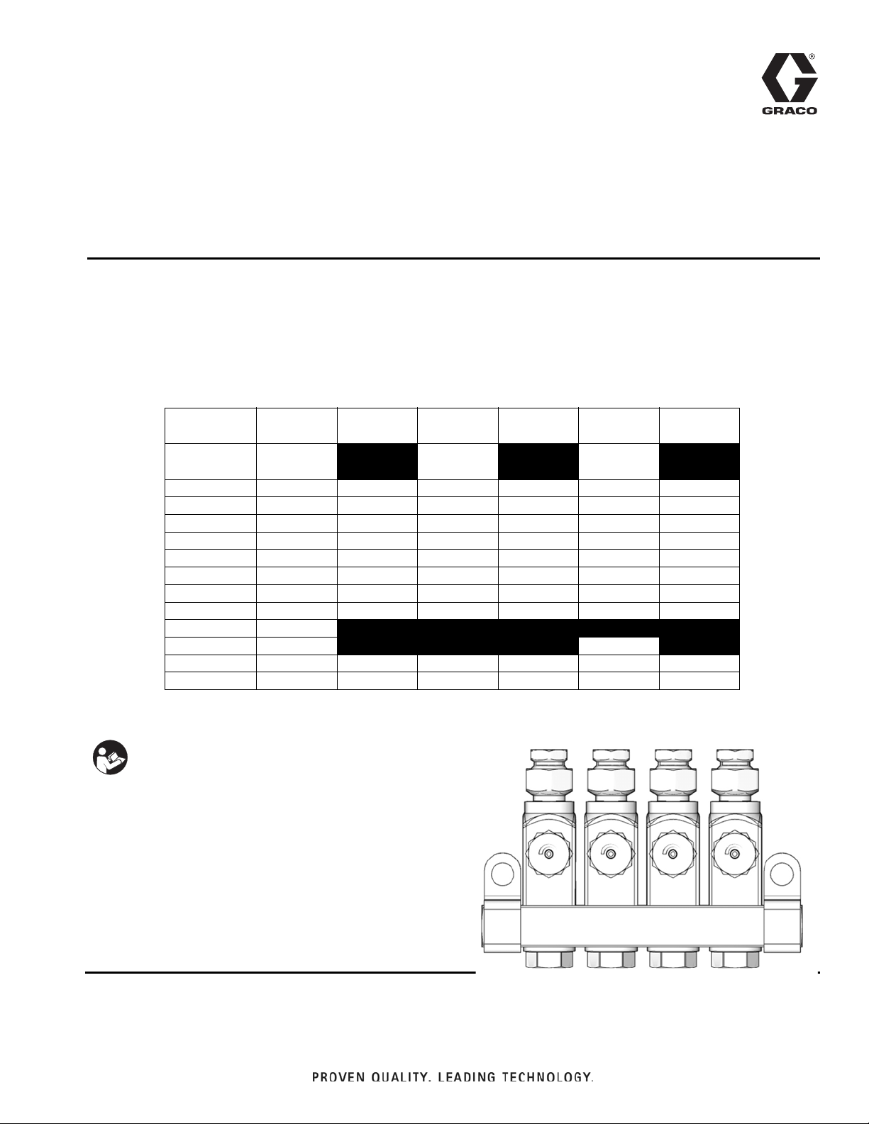
GL-33
®
(Grease) and
®
GL-42
For Single-Line, Parallel, and Automatic Injector Systems dispensing grease, N.L.G.I.
grades #000 - #2 and oil (minimum SAE 10 weight).
3500 psi (24 MPa, 241 bar) Maximum Working Pressure - Grease Models
1000 psi (6.89 MPa, 68.9 bar) Maximum Working Pressure - Oil Models
(Oil) Injectors
334495E
Model Nos.:
GL-33
1/8 NPTF
Stand-Alone 24W487
24W488
Replacement 24W483 24W484 24W485 24W486 24W491 24W492
Replacement* 25P458 25P459 25P460 25P461 25P462 25P463
1X Manifold 24W401 24W501 24W601 24W701 24W801 24W901
2X Manifold 24W402 24W502 24W602 24W702 24W802 24W902
3X Manifold 24W403 24W503 24W603 24W703 24W803 24W903
4X Manifold 24W404 24W504 24W604 24W704 24W804 24W904
5X Manifold 24X302 24X303 24X304 24X305 24X306 24X307
6X Manifold 24W405 24W505 24W605 24W705 24W805 24W905
7X Manifold 25R873
9X Manifold 24W406 24W806
10X Manifold 24W407 24W506 24W606 24W706 24W807 24W906
15X Manifold 24W408 24W507 24W607 24W707 24W808 24W907
*Replacements of individual injectors for corresponding Lincoln, Dropsa, and Bijur models
GL-33
1/8 BSPP
GL-33 SST
1/8 NPTF
24W489
24W490
GL-33 SST
1/8 BSPP
GL-42
1/8 NPTF
24W493
24W494
GL-42
1/8 BSPP
EN
Important Safety Instructions
Read all warnings and instructions in this manual and in the pump instruction manual included
with your system. Save all instructions.
Page 2
Warnings
WARNING
Warnings
The following warnings are for the setup, use, grounding, maintenance, and repair of this equipment. The
exclamation point symbol alerts you to a general warning and the hazard symbols refer to procedure-specific risks.
When these symbols appear in the body of this manual or on warning labels, refer back to these Warnings.
Product-specific hazard symbols and warnings not covered in this section may appear throughout the body of this
manual where applicable.
FIRE AND EXPLOSION HAZARD
When flammable fluids are present in the work area, such as gasoline and windshield wiper fluid, be
aware that flammable fumes can ignite or explode. To help prevent fire and explosion:
• Use equipment only in well ventilated area.
• Eliminate all ignition sources, such as cigarettes and portable electric lamps.
• Keep work area free of debris, including rags and spilled or open containers of solvent and gasoline.
• Do not plug or unplug power cords or turn lights on or off when flammable fumes are present.
• Ground all equipment in the work area.
• Use only grounded hoses.
• Stop operation immediately if static sparking occurs or you feel a shock. Do not use equipment
until you identify and correct the problem.
• Keep a working fire extinguisher in the work area.
SKIN INJECTION HAZARD
High-pressure fluid from dispensing device, hose leaks, or ruptured components will pierce skin. This
may look like just a cut, but it is a serious injury that can result in amputation. Get immediate surgical
treatment.
+
• Do not point dispensing device at anyone or at any part of the body.
• Do not put your hand over the fluid outlet.
• Do not stop or deflect leaks with your hand, body, glove, or rag.
• Follow the Pressure Relief Procedure when you stop dispensing and before cleaning, checking, or
servicing equipment.
• Tighten all fluid connections before operating the equipment.
• Check hoses and couplings daily. Replace worn or damaged parts immediately.
PERSONAL PROTECTIVE EQUIPMENT
Wear appropriate protective equipment when in the work area to help prevent serious injury, including
eye injury, hearing loss, inhalation of toxic fumes, and burns. This protective equipment includes but is
not limited to:
• Protective eyewear, and hearing protection.
• Respirators, protective clothing, and gloves as recommended by the fluid and solvent manufacturer.
2 334495E
Page 3
Installation
7
8
6
ti14179
Installation
Pressure Relief Procedure
Follow the Pressure Relief Procedure whenever
you see this symbol.
This equipment may stay pressurized or may become
pressurized by an automatic lubrication cycle initiated
by a lubrication controller. To help prevent serious
injury from pressurized fluid, such as skin injection,
splashing fluid and moving parts, follow the Pressure
Relief Procedure before cleaning, checking, or
servicing the equipment.
1. Disconnect power to the lubrication controller.
2. If connected to an air supply, disconnect air supply
to pump module to ensure the system is depressurized.
3. Consult your pump manual for any additional pressure relief instructions related to your pump module.
• The amount of dispensed volume can vary
depending on external conditions such as lubricant temperature and back pressure from the
downstream connection.
4. When the injector has been adjusted for the proper
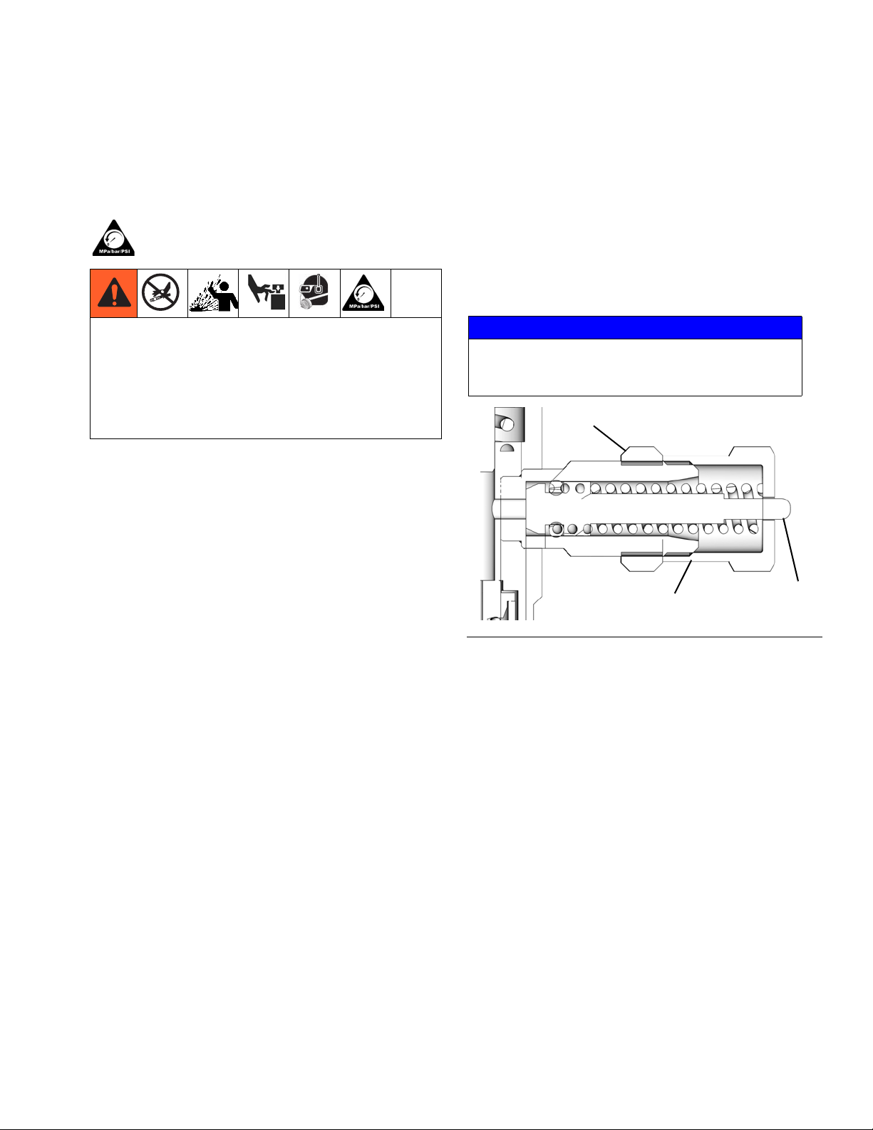
lubricant output, wrench tighten the stroke adjustment lock nut (7).
NOTICE
To prevent component failure, the adjustment nut (8)
must not be extended beyond the fully retracted
position of the piston (6). See F
IG. 1.
Adjustment Instructions
Reference numbers used in the following instructions
refer to F
1. Loosen lock nut (7).
2. Hand tighten the Adjuster Nut (8) then loosen,
3. Retracting the Adjuster Nut (8) one and three-quar-
IG. 1.
approximately 1/2 turn to achieve the minimum dispensed output volume (0.001 in.
NOTE: Any output setting below 1/2 turn should be
monitored to verify actual output volume.
ter turns from the hand-tight position permits a max-
imum dispensed output volume (0.003 in.
the factory, preset position.
NOTE:
• Each full turn out represents an addition of
approximately 0.0018 in.
3
).
3
volume output.
3
) This is
FIG. 1
334495E 3
Page 4
Installation
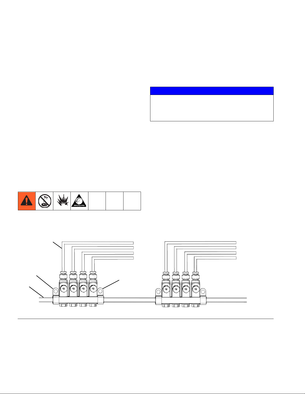
c
a
b
a
ti24505a
Installation Instructions
Reference letters used in the following instructions, refer
to F
IG. 2.
• Group injectors to minimize feed line length.
• Install injectors in locations that allow easy and safe
servicing access.
• Install injectors in areas that minimize accidental
injector damage by moving equipment.
• Injector outputs can be combined for a common
bearing point with a large grease requirement but
the output for a single injector cannot be split into
multiple bearing points.
• Graco recommends using steel tubing instead of
pipe and hose for supply lines when possible. Pipe
is often contaminated with scale and requires
proper cleaning prior to use. Hose lines expand
under pressure which leads to longer pump cycle
time.
1. Relieve pressure. See Pressure Relief Procedure,
page 3.
2. Install injectors on a flat, hard surface using mounting brackets (a).
3. Connect fluid supply line (c) to injectors.
NOTICE
To prevent rupturing supply lines due to over-pressurizing the components, only use supply lines and fittings that meet or exceed the pressure rating of the
injectors.
4. Connect lube point feed lines (b).
5. Flush the system with low viscosity oil or mineral
spirits to remove contamination introduced during
installation.
6. Use a purge gun or run the pump until clean lubricant is dispensed at the end of each feed line to
purge the system of flushing fluid or air.
7. Run the system at full output and verify that all injectors are cycling.
FIG. 2
8. Adjust injector volume output. (See Adjustment
Instructions, page 3.)
9. Connect feed lines to lubrication points.
4 334495E
Page 5
Operation
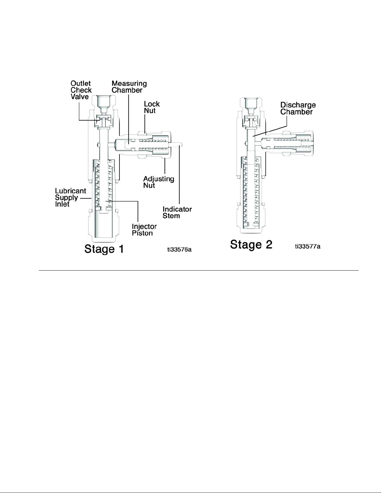
Operation
FIG. 3
Stage 1
Pressurized fluid moves the injector piston forward and
forces fluid through the outlet check valve to the feed
line.
Stage 2
After fluid is discharged, the pressure is relieved and the
injector piston returns to the rest position. Lubricant in
the measuring chamber returns to the discharge chamber.
334495E 5
Page 6

Operation
16
8
9
6
7
17
3
15
4
5
1
2
11
10
12
13
14
15
2
1
3
1
Torque to 15-16 ft. lbs (20.3 - 21.7 N•m)
1
Torque to 50-60 in. lbs (5.6 - 6.7 N•m)
2
Parts
Ref. Part No. Description Qty
17B871
17B951
17B872
17B952
17B873
17B953
17B874
17B954
17D731
17D733
1
17B875
17B955
19Y897
17B876
17B877
17B956
17B878
17B957
17B941
17B991
17B942
17B992
17B943
17B993
17B944
BLOCK, manifold, 1 injector, 1/8 NPTF
(model 24W401, 24W801)
BLOCK, manifold, SST, 1 injector, 1/8
NPTF (model 24W601)
BLOCK, manifold, 2 injector, 1/8 NPTF
(model 24W402, 24W802)
BLOCK, manifold, SST, 2 injector, 1/8
NPTF (model 24W602)
BLOCK, manifold, 3 injector, 1/8 NPTF
(model 24W403, 24W803)
BLOCK, manifold, SST, 3 injector, 1/8
NPTF (model 24W603)
BLOCK, manifold, 4 injector, 1/8 NPTF
(model 24W404, 24W804)
BLOCK, manifold, SST, 4 injector, 1/8
NPTF (model 24W604)
BLOCK, manifold, 5 injector, 1/8 NPTF
(models 24X302, 24X306)
BLOCK, manifold, SST, 5 injector, 1/8
NPTF (model 24X304)
BLOCK, manifold, 6 injector, 1/8 NPTF
(model 24W405, 24W805)
BLOCK, manifold, SST, 6 injector, 1/8
NPTF (model 24W605)
BLOCK, manifold, 7 injector, 1/8 NPTF
(model 25R873)
BLOCK, manifold, 9 injector, 1/8 NPTF
(model 24W406, 24W806)
BLOCK, manifold, 10 injector, 1/8
NPTF (model 24W407, 24W807)
BLOCK, manifold, SST, 10 injector, 1/8
NPTF (model 24W606)
BLOCK, manifold, 15 injector, 1/8
NPTF (model 24W408, 24W808)
BLOCK, manifold, SST, 15 injector, 1/8
NPTF (model 24W607)
BLOCK, manifold, 1 injector, 1/8 BSPP
(model 24W501, 24W901)
BLOCK, manifold, SST, 1 injector, 1/8
BSPP (model 24W701)
BLOCK, manifold, 2 injector, 1/8 BSPP
(model 24W502, 24W902)
BLOCK, manifold, SST, 2 injector, 1/8
BSPP (model 24W702)
BLOCK, manifold, 3 injector, 1/8 BSPP
(model 24W503, 24W903)
BLOCK, manifold, SST, 3 injector, 1/8
BSPP (model 24W703)
BLOCK, manifold, 4 injector, 1/8 BSPP
(model 24W504, 24W904)
1
1
1
1
1
1
1
1
1
1
1
1
1
1
1
1
1
1
1
1
1
1
1
1
1
6 334495E
Page 7

Operation
Ref. Part No. Description Qty
17B994
17D732
17D734
17B945
1
17B995
(cont)
17B946
17B996
17B947
17B997
2HOUSING 1
17B937
17B938
3
17B868
17B869
4PISTON, end 1
5 SPRING, compression, piston 1
6 PISTON, stroke 1
7 NUT, lock, stroke adjustment 1
8 ADJUSTER, nut, stroke, piston 1
9 SPRING, compression, piston 1
10 O-RING, 006, duro viton 1
11 VALVE, body, one-way 1
12† ADAPTER, outlet 1
13† FITTING, compression 1
14† ADAPTER, compression, nut 1
BLOCK, manifold, SST, 4 injector, 1/8
BSPP (model 24W704)
BLOCK, manifold, 5 injector, 1/8 BSPP
(models 24X303, 24X308)
BLOCK, manifold, SST, 5 injector, 1/8
BSPP (model 24X305)
BLOCK, manifold, 6 injector, 1/8 BSPP
(model 24W505, 24W905)
BLOCK, manifold, SST, 6 injector, 1/8
BSPP (model 24W705)
BLOCK, manifold, 10 injector, 1/8
BSPP (model 24W506, 24W906)
BLOCK, manifold, SST, 10 injector, 1/8
BSPP (model 24W706)
BLOCK, manifold, 15 injector, 1/8
BSPP (model 24W507, 24W907)
BLOCK, manifold, SST, 15 injector, 1/8
BSPP (model 24W707)
CYLINDER, inlet, 1/8-27 NPTF, stand
alone (models 24W487, 24W488,
24W493, 24W494)
CYLINDER, inlet, 1/8-27 NPTF, SST,
stand alone (model 24W489, 24W490)
CYLINDER, inlet, manifold (models
24W401-24W408, 24W501-24W507,
24W801-24W808, 24W901-24W907,
24W483, 24W484, 24W491, 24W492,
25P458, 25P459, 25P462, 25P463,
25R873)
CYLINDER, inlet, SST, manifold (models 24W601-24W607,
24W701-24W707, 24W485, 24W486,
25P460, 25P461)
1
1
1
1
1
1
1
1
1
1
1
1
1
Ref. Part No. Description Qty
GASKET, manifold inlet (models
24W401- 24W408, 24W501-24W507,
17B885
15
18A980
18B026
17B948
16
17B949 CLIP, manifold (all SST models) 1
17 123962 SEAL, square, GL-Series 1
Parts included in Injector Repair Kit:
Grease:
24W913 - GL-33 carbon steel;
24W914 - GL-33 stainless steel;
Oil:
24W915 - GL-42
Parts included in 1/8” Outlet Fitting Kit 24B677;
SST - 24F943
Parts included in 4 mm Outlet Fitting
†
(Adapter) Kit 24F513; SST- 24F555
Parts included in 6 mm Outlet Fitting Kit 24F514; SST-
24F556
24W601-24W607, 24W701-24W707,
24W801-24W808, 24W901-24W907,
24W483-24W494, 25R873)
SPACER, copper, GL33 (models
25P458, 25P459, 25P462, 25P463)
SPACER, SST, GL33 (models 25P460,
25P461)
CLIP, manifold (all carbon steel models)
2
2
2
2
334495E 7
Page 8

Operation
Accessories
JIC-4 Fitting:
17B168 - Carbon Steel
17B169 - Stainless Steel
1/8 inch NPTF Female Outlet Adapter:
17B780 - Carbon Steel
17B781 - Stainless Steel
Tube Push-to-Connect Adapter:
17B879 - 1/8 inch O.D.
17B880 - 1/4 inch O.D.
Manual Grease Fitting Adapter: 24W495
Outlet Plug:
17B782 - Carbon Steel
17B783 - Stainless Steel
Adjustment Nut Cap: 17B785
Tube Outlet Adapter:
†24F513 - 4 MM O.D.,
carbon steel
†24F555 - 4 MM O.D.,
stainless steel
24B677 - 1/8 in. O.D.,
carbon steel
24F943 - 1/8 in. O.D.,
stainless steel
24F514 - 6 mm O.D.,
carbon steel
24F556 - 6 mm O.D.,
stainless steel
8 334495E
Page 9

Technical Data
Oil Models
US Metric
Maximum Operating Pressure 1000 psi 6.89 MPa, 68.9 bar
Minimum Operating Pressure 750 psi 5.17 MPa, 51.7 bar
Suggested Operating Pressure 850 psi 5.86 MPa, 58.6 bar
Reset Pressure 150 psi 1.03 MPa, 10.3 bar
Output Volume per Cycle
Wetted Parts carbon steel, stainless steel, fluoroelastomer
Recommended Fluids Minimum SAE 10 weight oil*
adjustable: 0.001 - 0.003 in.
Grease Models
3
adjustable: 0.016 - 0.049 cc
Technical Data
US Metric
Maximum Operating Pressure 3500 psi 24 MPa, 241 bar
Minimum Operating Pressure 1200 psi 8.3 MPa, 83 bar
Suggested Operating Pressure 1500 psi 10.3 MPa, 103.4 bar
Reset Pressure 200 psi 1.4 MPa, 14 bar
Output Volume per Cycle
Wetted Parts carbon steel, stainless steel, fluoroelastomer
Recommended Fluids Grease N.L.G.I. grades #000 - #2*
*Only use fluids appropriate for your application, automatic dispensing and the equipment’s operating temperature.
Consult with machine and lube manufacturer for details.
adjustable: 0.001 - 0.003 in.
3
adjustable: 0.016 - 0.049 cc
334495E 9
Page 10

Technical Data
A
B
D
F (OD tubing dispense outlet)
E
C
G
H
J
K
M
J
ti24500
Dimensions
M*
7.0
NPTF or
BSPP
1/8 in.
NPTF
OR
1/8 in.
BSPP
Injector
Stand
alone
Manifold
1 point
manifold
2 point
manifold
3 point
manifold
4 point
manifold
5 point
manifold
6 point
manifold
7 point
manifold
9 point
manifold
10 point
manifold
15 point
manifold
in. / mm Bin./mm
single
injector
replacement for
1.13/
0.57
1.88/
47.8
2.63/
66.8
3.38/
85.8
4.13/
104.9
4.88/
124
5.63/
143
7.13/
181
7.88/
200
11.63/
295
manifold
manifold
1.63/
41.4
2.38/
60.5
3.13/
79.5
3.88/
98.5
4.63/
117.6
5.38/
136.7
6.13/
155.7
7.63/
193
8.38/
213
12.13/
308
A
in./mm
2.54/
64.6
C
D
in./mm
N/A
E
in./mmF†in./mmGin./mmHin./mmJin./mmKin./mm
0.75/
19.0
0.62/
15.8
0.125/
3.2
OR
0.236/
6.0
1.4/
35.4
40.6
1.6/
0.41/
10.4
0.275/
*To verify your injector’s inlet / outlet thread type (M), see Model Nos. table provided on cover page of this manual.
† 0.157/4.0 available as adapter kit.
10 334495E
Page 11

Notes
Notes
334495E 11
Page 12

Graco Standard Warranty
Graco warrants all equipment referenced in this document which is manufactured by Graco and bearing its name to be free from defects in
material and workmanship on the date of sale to the original purchaser for use. With the exception of any special, extended, or limited warranty
published by Graco, Graco will, for a period of twelve months from the date of sale, repair or replace any part of the equipment determined by
Graco to be defective. This warranty applies only when the equipment is installed, operated and maintained in accordance with Graco’s written
recommendations.
This warranty does not cover, and Graco shall not be liable for general wear and tear, or any malfunction, damage or wear caused by faulty
installation, misapplication, abrasion, corrosion, inadequate or improper maintenance, negligence, accident, tampering, or substitution of
non-Graco component parts. Nor shall Graco be liable for malfunction, damage or wear caused by the incompatibility of Graco equipment with
structures, accessories, equipment or materials not supplied by Graco, or the improper design, manufacture, installation, operation or
maintenance of structures, accessories, equipment or materials not supplied by Graco.
This warranty is conditioned upon the prepaid return of the equipment claimed to be defective to an authorized Graco distributor for verification of
the claimed defect. If the claimed defect is verified, Graco will repair or replace free of charge any defective parts. The equipment will be returned
to the original purchaser transportation prepaid. If inspection of the equipment does not disclose any defect in material or workmanship, repairs will
be made at a reasonable charge, which charges may include the costs of parts, labor, and transportation.
THIS WARRANTY IS EXCLUSIVE, AND IS IN LIEU OF ANY OTHER WARRANTIES, EXPRESS OR IMPLIED, INCLUDING BUT NOT LIMITED
TO WARRANTY OF MERCHANTABILITY OR WARRANTY OF FITNESS FOR A PARTICULAR PURPOSE.
Graco’s sole obligation and buyer’s sole remedy for any breach of warranty shall be as set forth above. The buyer agrees that no other remedy
(including, but not limited to, incidental or consequential damages for lost profits, lost sales, injury to person or property, or any other incidental or
consequential loss) shall be available. Any action for breach of warranty must be brought within two (2) years of the date of sale.
GRACO MAKES NO WARRANTY, AND DISCLAIMS ALL IMPLIED WARRANTIES OF MERCHANTABILITY AND FITNESS FOR A
PARTICULAR PURPOSE, IN CONNECTION WITH ACCESSORIES, EQUIPMENT, MATERIALS OR COMPONENTS SOLD BUT NOT
MANUFACTURED BY GRACO. These items sold, but not manufactured by Graco (such as electric motors, switches, hose, etc.), are subject to
the warranty, if any, of their manufacturer. Graco will provide purchaser with reasonable assistance in making any claim for breach of these
warranties.
In no event will Graco be liable for indirect, incidental, special or consequential damages resulting from Graco supplying equipment hereunder, or
the furnishing, performance, or use of any products or other goods sold hereto, whether due to a breach of contract, breach of warranty, the
negligence of Graco, or otherwise.
FOR GRACO CANADA CUSTOMERS
The Parties acknowledge that they have required that the present document, as well as all documents, notices and legal proceedings entered into,
given or instituted pursuant hereto or relating directly or indirectly hereto, be drawn up in English. Les parties reconnaissent avoir convenu que la
rédaction du présente document sera en Anglais, ainsi que tous documents, avis et procédures judiciaires exécutés, donnés ou intentés, à la suite
de ou en rapport, directement ou indirectement, avec les procédures concernées.
Graco Information
For the latest information about Graco products, visit www.graco.com.
For patent information, see www.graco.com/patents.
TO PLACE AN ORDER, contact your Graco distributor or call to identify the nearest distributor.
Phone: 612-623-6928 or Toll Free: 1-800-533-9655, Fax: 612-378-3590
All written and visual data contained in this document reflects the latest product information available at the time of publication.
GRACO INC. AND SUBSIDIARIES • P.O. BOX 1441 • MINNEAPOLIS MN 55440-1441 • USA
Copyright 2014, Graco Inc. All Graco manufacturing locations are registered to ISO 9001.
Graco reserves the right to make changes at any time without notice.
Original instructions. This manual contains English. MM 334495
Graco Headquarters: Minneapolis
International Offices: Belgium, China, Japan, Korea
www.graco.com
May 2020
 Loading...