

Page 1
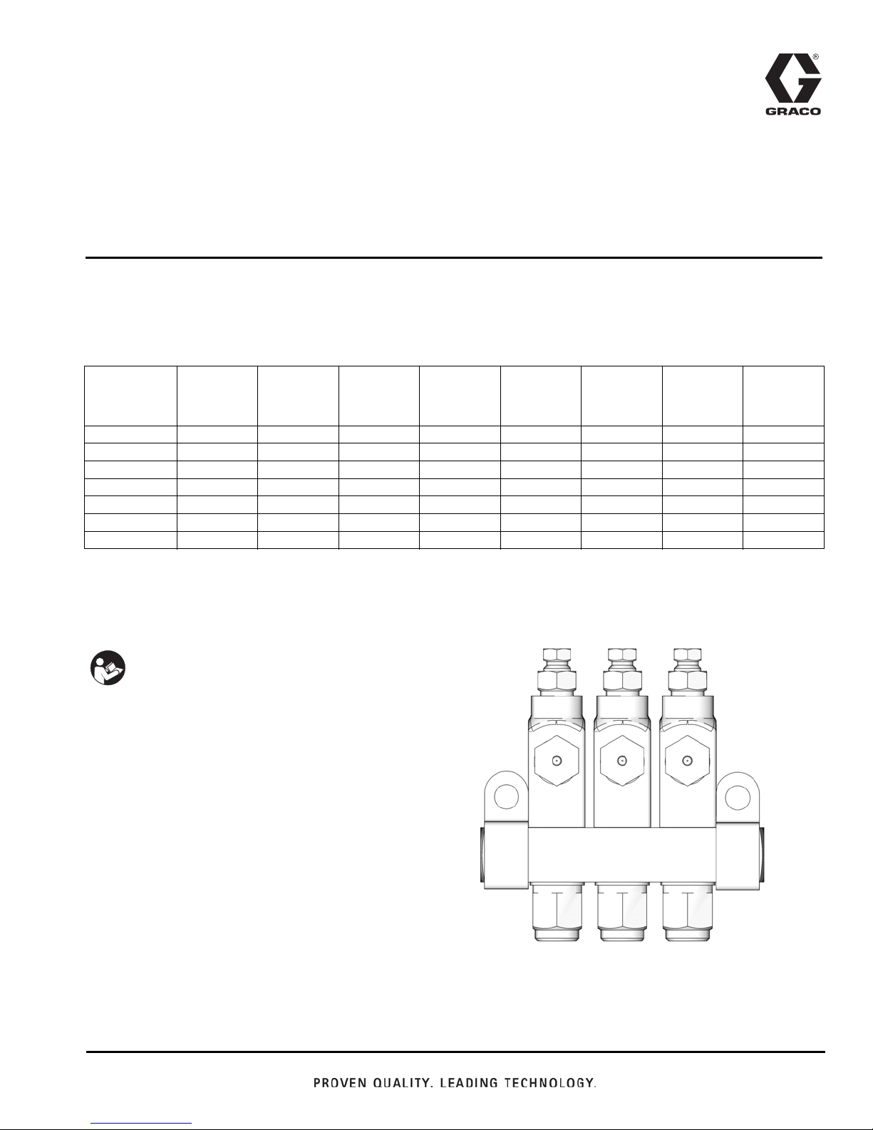
Instructions
GL-32
®
(Grease) and
®
GL-43
For Single-Line, Parallel, and Automatic Injector Systems Dispensing Grease, N.L.G.I.
grades #000 - #2 and Oil (minimum SAE 10 weight).
(Oil) Injectors
313798S
Model Nos.:
GL-32
1/4 NPT
CS
Outlet 3.2 mm 6 mm 3.2 mm 6 mm 3.2 mm 6 mm 6 mm 3.2 mm
Stand-Alone 24A919 NA 24E389 NA 24E240 NA NA NA
Replacement 24A920 24F508 24E390 24F550 24E245 24F543 26C065 24W508
1X Manifold 24A921 24F509 24E391 24F551 24E241 24F544 NA NA
2X Manifold 24A922 24F510 24E392 24F552 24E242 24F545 24Z542 NA
3X Manifold 24A923 24F511 24E393 24F553 24E243 24F546 NA 24W916
4X Manifold 24A924 24F512 24E394 24F554 24E244 24F548 24Z544 24W917
3500 psi (24 MPa, 241 bar) Maximum Working Pressure - Grease Models
1000 psi (6.89 MPa, 68.9 bar) Maximum Working Pressure - Oil Models
GL-32
1/8 BSPP
CS
GL-32 SST
1/4 NPT
SST
GL-32 SST
1/8 BSPP
SST
GL-43
1/4 NPT
CS
GL-43
1/8 BSPP
CS
GL-32
1/4 NPT
CS
GL-32
1/4 NPT
CS
EN
Important Safety Instructions
Read all warnings and instructions in this
manual. Save these instructions.
Page 2
7
8
6
ti14179
Warnings
SKIN INJECTION HAZARD
High-pressure fluid from dispense valve, hose leaks, or ruptured components will pierce skin. This may look like just a
cut, but it is a serious injury that can result in amputation. Get
immediate surgical treatment.
• Do not point dispense valve at anyone or at any part of
the body.
• Do not put your hand over the dispense nozzle.
• Do not stop or deflect leaks with your hand, body, glove,
or rag.
• Follow Pressure Relief Procedure in this manual, when
you stop dispensing and before cleaning, checking, or
servicing equipment.
Pressure Relief Procedure
The equipment may be pressurized or may become
pressurized by an automatic lubrication cycle initiated by
a lubrication controller such as a timer. To avoid serious
injury including the kind of injuries described in the Skin
Injection Hazard warning:
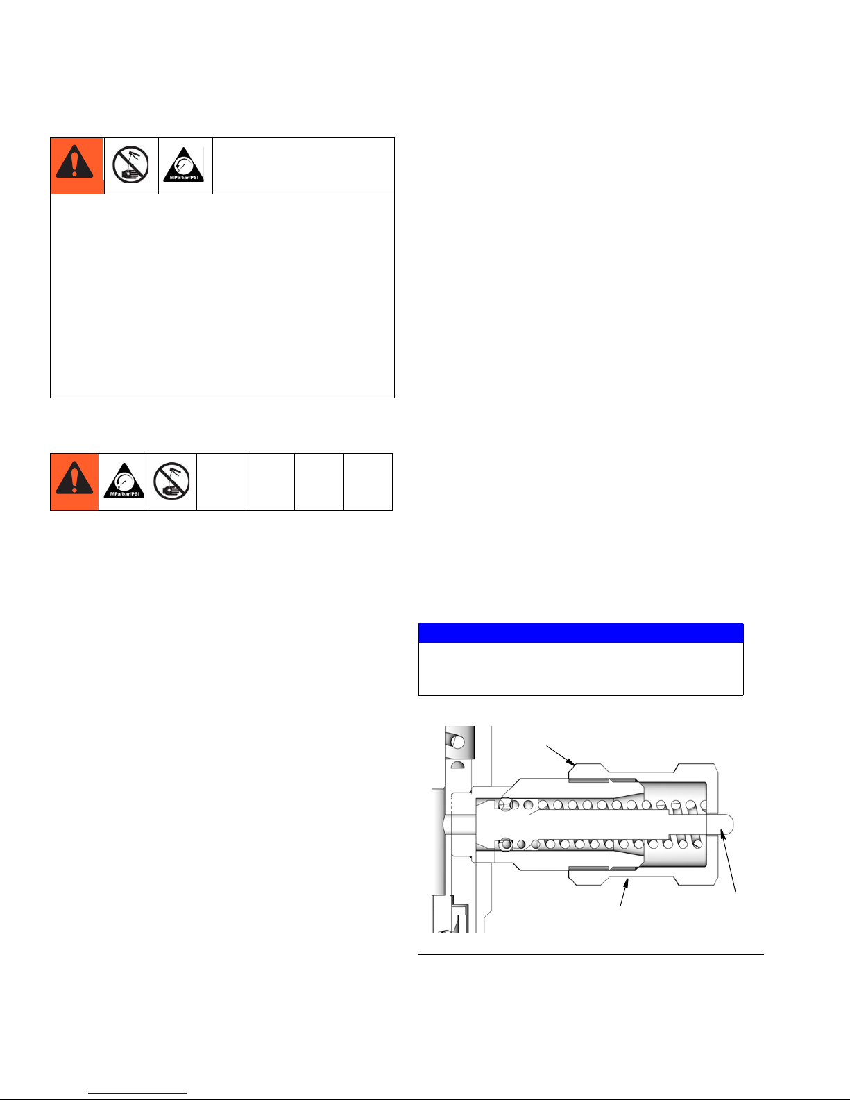
Adjustment Instructions
Reference numbers refer to parts (FIG. 1 and page 4).
1. Loosen lock nut (7).
2. Hand tighten the Adjuster Nut (8) then loosen,
approximately 1/2 turn to achieve the minimum dis-
pensed output volume (.001 in.
NOTE: Any output setting below 1/2 turn should be
monitored to verify actual output volume.
3. Retracting the Adjuster Nut (8) five full turns from
the hand-tight position permits a maximum dis-
pensed output volume (.008 in.
preset position.
NOTE:
• Each full turn out represents an addition of
approximately 0.0014 in.
• The amount of dispensed volume can vary
depending on external conditions such as lubricant temperature and back pressure from the
downstream connection.
4. When the injector has been adjusted for the proper
lubricant output, wrench tighten the stroke adjustment lock nut (7).
3
).
3
) This is the factory,
3
volume output.
1. Disconnect power to the timer.
2. If connected to an air supply, disconnect air supply
to pump module to ensure the system is depressurized.
3. Consult your pump manual for any additional pressure relief instructions related to your pump module.
NOTICE
To prevent component failure, the adjustment nut (8)
must not be extended beyond the fully retracted
position of the piston (6). See F
IG. 1
F
IG. 1.
2 313798S
Page 3
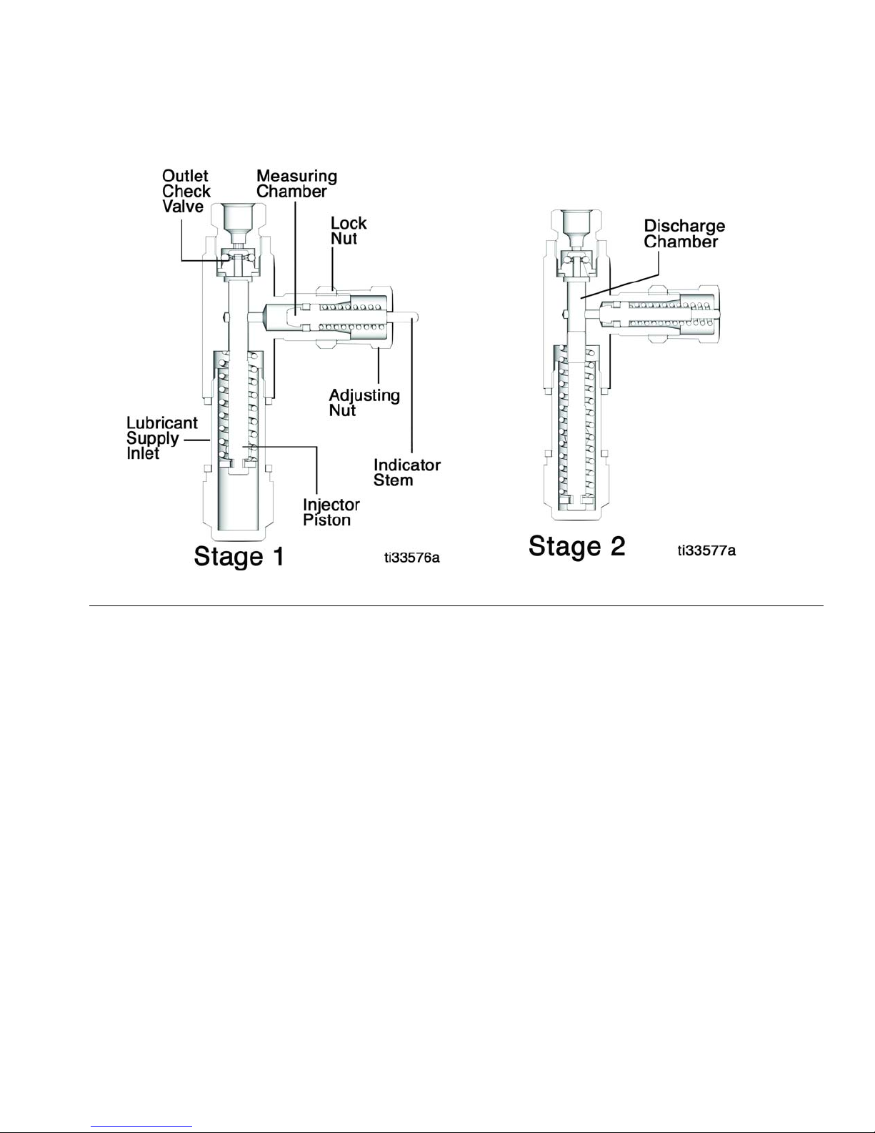
Operation
Operation
FIG. 2
Stage 1
Pressurized fluid moves the injector piston forward and
forces fluid through the outlet check valve to the feed
line.
Stage 2
After fluid is discharged, the pressure is relieved and the
injector piston returns to the rest position. Lubricant in
the measuring chamber returns to the discharge chamber.
313798S 3
Page 4

Operation
16
8
9
6
7
17
3
15
4
5
1
2
11
10
12
13
14
15
2
1
ti13950
3
1
Carbon Steel Models - Torque to 18-19 ft. lbs (24.4 -
25.7 N•m)
Stainless Steel Models - Torque to 23-26 ft. lbs
(31.2-35.3 N•m)
1
Torque to 50-60 in. lbs (5.6 - 6.7 N•m)
2
Parts
Pa
Ref. Part No. Description Qty
1 15W661 BLOCK, manifold, 1 injector , 1/4 NPT
16M401 BLOCK, manifold, SST, 1 injector, 1/4
15W662 BLOCK, manifold, 2 injectors, 1/4 NPT
16M402 BLOCK, manifold, SST, 2 injectors, 1/4
15W663 BLOCK, manifold, 3 injectors, 1/4 NPT
16M403 BLOCK, manifold, SST, 3 injectors, 1/4
15W664 BLOCK, manifold, 4 injectors, 1/4 NPT
16M404 BLOCK, manifold, SST, 4 injectors, 1/4
16F341 BLOCK, manifold, 1 injector, 1/8 BSPP
16M405 BLOCK, manifold, SST, 1 injector, 1/8
16F342 BLOCK, manifold, 2 injectors, 1/8
16M406 BLOCK, manifold, SST, 2 injectors, 1/8
16F343 BLOCK, manifold, 3 injectors, 1/8
16M407 BLOCK, manifold, SST, 3 injectors, 1/8
16F344 BLOCK, manifold, 4 injectors, 1/8
16M408 BLOCK, manifold, SST, 4 injectors, 1/8
2HOUSING 1
3 15W671 CYLINDER, inlet, 1/4-18 NPTF, stand
15W657‡ CYLINDER, inlet, manifold (model
124154 CYLINDER, inlet, SST, manifold (model
4 PISTON, end 1
5 SPRING, compression, piston 1
6 PISTON, stroke 1
7 NUT, lock, stroke adjustment 1
8 ADJUSTER, nut, stroke, piston 1
9 SPRING, compression, piston 1
10 O-RING, 006, duro viton 1
11 VALVE, body, one-way 1
12†
13†
14
†
(model 24A921, 24E241)
NPT (model 24E391)
(model 24A922, 24E242, 24Z542)
NPT (model 24E392)
(model 24A923, 24E243, 15W663)
NPT (model 24E393)
(model 24A924, 24E244, 24Z544,
24W917)
NPT (model 24E394)
(model 24F509, 24F544)
BSPP (model 24F551)
BSPP (model 24F510, 24F545)
BSPP (model 24F552)
BSPP (model 24F511, 24F546)
BSPP (model 24F553)
BSPP (model 24F512, 24F548)
BSPP (model 24F554)
alone, (model 24A919)
CYLINDER, inlet, 1/4-18 NPTF, SST,
stand alone, (model 24E389)
CYLINDER, inlet, 1/4-18 NPTF, stand
alone, oil (model 24E240)
24A920-24A924; 24E241-24E245,
24W508, 24W916, 24W917,
24F508-24F512, 24F543-24F546,
24F548, 24Z542, 24Z544, 26C065)
24E390-24E394;
24F550- 24F554)
ADAPTER, outlet 1
FITTING, compression 1
ADAPTER, compression, nut 1
1
1
1
1
1
1
1
1
1
1
1
1
1
1
1
1
1
1
1
1
4 313798S
Page 5

Ref. Part No. Description Qty
15 SPACER, manifold inlet 2
16 15W658 CLIP, manifold (all non-SST models
only, 24A921-24A924, 24F509-24F512;
24E241-24E244; 24Z542, 24Z544,
24F544, 24F545, 24F546, 24F548.
24W916, 24W917)
124619 CLIP, SST, manifold (models,
24E391-24E394; 24F551-24F554)
17 123962 SEAL, square, GL-Series 1
‡ 131252 SEAL, square, GL-Series (for low tem-
perature applications)
Parts included in Injector Repair Kit 24B360,
Oil - 24F201; SST - 24F944
Parts included in 1/8” Outlet Fitting Kit 24B677;
SST - 24F943
† Parts included in 4 mm Outlet Fitting
(Adapter) Kit 24F513; SST- 24F555
Parts included in 6 mm Outlet Fitting Kit 24F514; SST-
24F556
‡ Parts included in Indicator Pin Kit 25C066 for low tem-
perature applications.
Technical Data
2
1
Technical Data
Oil Models
Maximum Operating Pressure 1000 psi (6.89 MPa, 68.9 bar)
Minimum Operating Pressure 750 psi (5.17 MPa, 51.7 bar)
Suggested Operating Pressure 850 psi (5.86 MPa, 58.6 bar)
Reset Pressure 150 psi (1.03 MPa, 10.3 bar)
Output Volume per Cycle
adjustable: 0.001 - 0.008 in.
Wetted Parts carbon steel, stainless steel, copper, fluoroelastomer
Recommended Fluids Minimum SAE 10 weight oil*
Grease Models
Maximum Operating Pressure 3500 psi (24 MPa, 241 bar)
Minimum Operating Pressure 1200 psi (8.3 MPa, 83 bar)
Suggested Operating Pressure 2500 psi (17 MPa, 172 bar)
Reset Pressure 200 psi (1.4 MPa, 14 bar)
Output Volume per Cycle
Wetted Parts carbon steel, stainless steel, copper, fluoroelastomer,
Recommended Fluids Grease N.L.G.I. grades #000 - #2*
*Only use fluids appropriate for your application, automatic dispensing and the equipment’s operating temperature.
Consult with machine and lube manufacturer for details.
adjustable: 0.001 - 0.008 in.
TPU
3
(0.016 - 0.131 cc)
3
(0.016 - 0.131 cc)
313798S 5
Page 6

Technical Data
A
B
D
F (OD tubing dispense outlet)
E
ti13949
C
G
H
J
K
K
M
Dimensions
A
Injector
Stand
alone
Manifold replacement for
1 point
manifold
2 point
manifold
3 point
manifold
4 point
manifold
*To verify your injector’s inlet / outlet thread type (M), see Model Nos. table provided on cover page of this manual.
in. / mm
single
injector
1.14/
28.9 CS
1.14/
28.9 SST
1.90/
48.26 CS
2.00/
50.8 SST
2.64/
67.06 CS
2.84/
72.14 SST
3.39/
86.11 CS
3.69/
93.73 SST
manifold
B
in./mm
manifold
1.75/
44.4 CS
1.75/
44.4 SST
2.50 /
63.5 CS
2.60/
66.0 SST
3.25/
82.5 CS
3.45/
87.6 SST
4.00/
101.6 CS
4.30/
109.2 SST
† 0.157/4.0 available as adapter kit.
C
in./mm
3.12/
79.4
3.12/
79.4
3.12/
79.4
3.12/
79.4
3.12/
79.4
D
in./mm
N/A
0.75/
19.0 CS
0.85/
21.6 SST
0.75/
19.0 CS
0.85/
21.6 SST
0.75/
19.0 CS
0.85/
21.6 SST
E
in./mmF†in./mmGin./mmHin./mmJin./mmKin./mm
0.68/
17.3
0.68/
17.3
0.68/
17.3
0.68/
17.3
0.68/
17.3
0.125/
3.2
OR
0.236/
6.0
1.88/
47.75
1.92/
48.77
0.46/
11.68
Ø
0.21/
7.14
M*
NPT or
BSPP
1/4”
NPT
or
1/8”
BSPP
6 313798S
Page 7

Notes
Notes
313798S 7
Page 8

Graco Standard Warranty
Graco warrants all equipment referenced in this document which is manufactured by Graco and bearing its name to be free from defects in
material and workmanship on the date of sale to the original purchaser for use. With the exception of any special, extended, or limited warranty
published by Graco, Graco will, for a period of twelve months from the date of sale, repair or replace any part of the equipment determined by
Graco to be defective. This warranty applies only when the equipment is installed, operated and maintained in accordance with Graco’s written
recommendations.
This warranty does not cover, and Graco shall not be liable for general wear and tear, or any malfunction, damage or wear caused by faulty
installation, misapplication, abrasion, corrosion, inadequate or improper maintenance, negligence, accident, tampering, or substitution of
non-Graco component parts. Nor shall Graco be liable for malfunction, damage or wear caused by the incompatibility of Graco equipment with
structures, accessories, equipment or materials not supplied by Graco, or the improper design, manufacture, installation, operation or
maintenance of structures, accessories, equipment or materials not supplied by Graco.
This warranty is conditioned upon the prepaid return of the equipment claimed to be defective to an authorized Graco distributor for verification of
the claimed defect. If the claimed defect is verified, Graco will repair or replace free of charge any defective parts. The equipment will be returned
to the original purchaser transportation prepaid. If inspection of the equipment does not disclose any defect in material or workmanship, repairs will
be made at a reasonable charge, which charges may include the costs of parts, labor, and transportation.
THIS WARRANTY IS EXCLUSIVE, AND IS IN LIEU OF ANY OTHER WARRANTIES, EXPRESS OR IMPLIED, INCLUDING BUT NOT LIMITED
TO WARRANTY OF MERCHANTABILITY OR WARRANTY OF FITNESS FOR A PARTICULAR PURPOSE.
Graco’s sole obligation and buyer’s sole remedy for any breach of warranty shall be as set forth above. The buyer agrees that no other remedy
(including, but not limited to, incidental or consequential damages for lost profits, lost sales, injury to person or property, or any other incidental or
consequential loss) shall be available. Any action for breach of warranty must be brought within two (2) years of the date of sale.
GRACO MAKES NO WARRANTY, AND DISCLAIMS ALL IMPLIED WARRANTIES OF MERCHANTABILITY AND FITNESS FOR A
PARTICULAR PURPOSE, IN CONNECTION WITH ACCESSORIES, EQUIPMENT, MATERIALS OR COMPONENTS SOLD BUT NOT
MANUFACTURED BY GRACO. These items sold, but not manufactured by Graco (such as electric motors, switches, hose, etc.), are subject to
the warranty, if any, of their manufacturer. Graco will provide purchaser with reasonable assistance in making any claim for breach of these
warranties.
In no event will Graco be liable for indirect, incidental, special or consequential damages resulting from Graco supplying equipment hereunder, or
the furnishing, performance, or use of any products or other goods sold hereto, whether due to a breach of contract, breach of warranty, the
negligence of Graco, or otherwise.
FOR GRACO CANADA CUSTOMERS
The Parties acknowledge that they have required that the present document, as well as all documents, notices and legal proceedings entered into,
given or instituted pursuant hereto or relating directly or indirectly hereto, be drawn up in English. Les parties reconnaissent avoir convenu que la
rédaction du présente document sera en Anglais, ainsi que tous documents, avis et procédures judiciaires exécutés, donnés ou intentés, à la suite
de ou en rapport, directement ou indirectement, avec les procédures concernées.
Graco Information
For the latest information about Graco products, visit www.graco.com.
TO PLACE AN ORDER, contact your Graco distributor or call to identify the nearest distributor.
Phone: 612-623-6928 or Toll Free: 1-800-533-9655, Fax: 612-378-3590
All written and visual data contained in this document reflects the latest product information available at the time of publication.
Graco reserves the right to make changes at any time without notice.
Original instructions. This manual contains English. MM 313798
For Patent Information see www.graco.com/patents
International Offices: Belgium, China, Japan, Korea
GRACO INC. P.O. BOX 1441 MINNEAPOLIS, MN 55440-1441
Copyright 2009, Graco Inc. is registered to ISO 9001
Graco Headquarters: Minneapolis
www.graco.com
Revised March 2018
 Loading...