

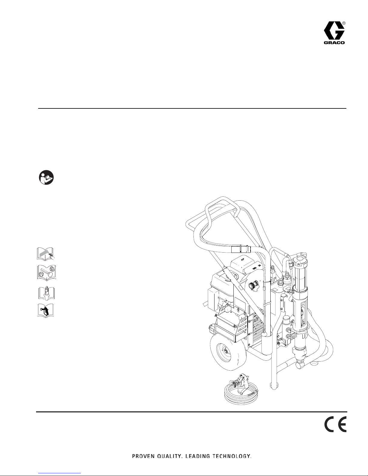
Graco GH 833 249318, GH 833 253471, GH 833 253472, GH 833 249617, GH 833 16U287 Repair Manual
...
Repair
ti21208a
™
GH
For use with Architectural Coatings, Paints, Roof Coatings and Below Grade Coatings. For
professional use only.
833 Sprayers
311283H
EN
Models: 249318, 249617, 253471, 253472, 16U287, 16U288, 16V258, 16V260
4000 psi (27.6 MPa, 275.8 bar) Maximum Working Pressure
IMPORTANT SAFETY INSTRUCTIONS
Read all warnings and instructions in this manual and related manuals.
Be familiar with the controls and the proper usage of the equipment.
Save these instructions.
Related Manuals
311279
311484
311485
311254
Warning
WARNINGWARNINGWARNING
WARNING
Warning
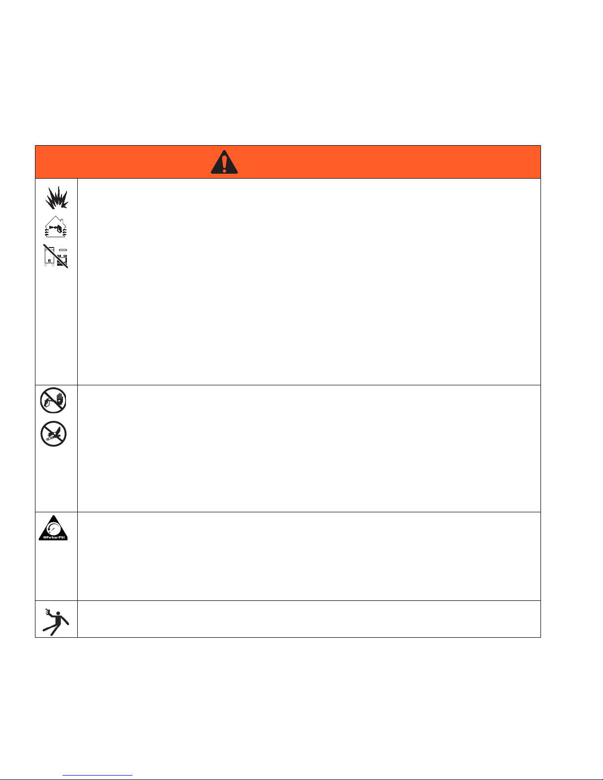
The following warnings are for the setup, use, grounding, maintenance, and repair of this equipment. The exclama
tion point symbol alerts you to a general warning and the hazard symbols refer to procedure-specific risks. When
these symbols appear in the body of this manual, refer back to these Warnings. Product-specific hazard symbols and
warnings not covered in this section may appear throughout the body of this manual where applicable.
FIRE AND EXPLOSION HAZARD
Flammable fumes, such as solvent and paint fumes, in work area can ignite or explode. To help prevent
fire and explosion:
• Use equipment only in well ventilated area.
• Do not fill fuel tank while engine is running or hot; shut off engine and let it cool. Fuel is flammable and
can ignite or explode if spilled on hot surface.
• Eliminate all ignition sources; such as pilot lights, cigarettes, portable electric lamps, and plastic drop
cloths (potential static arc).
• Keep work area free of debris, including solvent, rags and gasoline.
• Do not plug or unplug power cords, or turn power or light switches on or off when flammable fumes are
present.
• Ground all equipment in the work area. See Grounding instructions.
• Use only grounded hoses.
• Hold gun firmly to side of grounded pail when triggering into pail.
• If there is static sparking or you feel a shock, stop operation immediately. Do not use equipment until
you identify and correct the problem.
• Keep a working fire extinguisher in the work area.
SKIN INJECTION HAZARD
High-pressure fluid from gun, hose leaks, or ruptured components will pierce skin. This may look like just a
cut, but it is a serious injury that can result in amputation. Get immediate surgical treatment.
• Do not point gun at anyone or at any part of the body.
• Do not put your hand over the spray tip.
• Do not stop or deflect leaks with your hand, body, glove, or rag.
• Do not spray without tip guard and trigger guard installed.
• Engage trigger lock when not spraying.
• Follow Pressure Relief Procedure in this manual, when you stop spraying and before cleaning,
checking, or servicing equipment.
PRESSURIZED EQUIPMENT HAZARD
Fluid from the gun/dispense valve, leaks, or ruptured components can splash in the eyes or on skin and
cause serious injury.
• Follow Pressure Relief Procedure in this manual, when you stop spraying and before cleaning,
checking, or servicing equipment.
• Tighten all fluid connections before operating the equipment.
• Check hoses, tubes, and couplings daily. Replace worn or damaged parts immediately.
RECOIL HAZARD
Brace yourself; gun may recoil when triggered and cause you to fall, which could cause serious injury.
2 311283H
Warning
WARNINGWARNINGWARNING
WARNING
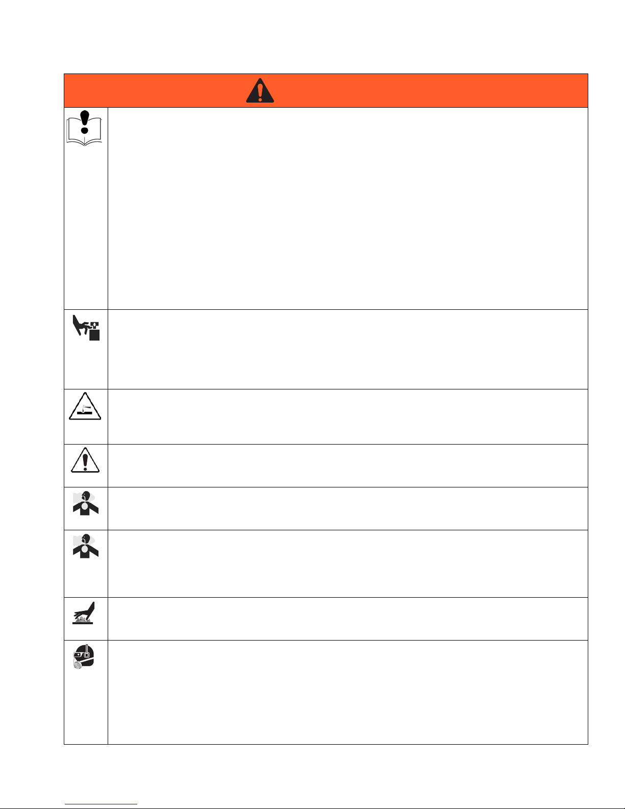
EQUIPMENT MISUSE HAZARD
Misuse can cause death or serious injury.
• Do not operate the unit when fatigued or under the influence of drugs or alcohol.
• Do not exceed the maximum working pressure or temperature rating of the lowest rated system com
ponent. See Technical Data in all equipment manuals.
• Use fluids and solvents that are compatible with equipment wetted parts. See Technical Data in all
equipment manuals. Read fluid and solvent manufacturer’s warnings. For complete information about
your material, request MSDS forms from distributor or retailer.
• Check equipment daily. Repair or replace worn or damaged parts immediately with genuine Manufac
turer’s replacement parts only.
• Do not alter or modify equipment.
• Use equipment only for its intended purpose. Call your distributor for information.
• Route hoses and cables away from traffic areas, sharp edges, moving parts, and hot surfaces.
• Do not kink or over bend hoses or use hoses to pull equipment.
• Keep children and animals away from work area.
• Comply with all applicable safety regulations.
MOVING PARTS HAZARD
Moving parts can pinch or amputate fingers and other body parts.
• Keep clear of moving parts.
• Do not operate equipment with protective guards or covers removed.
• Pressurized equipment can start without warning. Before checking, moving, or servicing equipment,
follow the Pressure Relief Procedure in this manual. Disconnect power or air supply.
PRESSURIZED ALUMINUM PARTS HAZARD
Do not use 1,1,1-trichloroethane, methylene chloride, other halogenated hydrocarbon solvents or fluids
containing such solvents in pressurized aluminum equipment. Such use can cause serious chemical reac
tion and equipment rupture, and result in death, serious injury, and property damage.
SUCTION HAZARD
Never place hands near the pump fluid inlet when pump is operating or pressurized. Powerful suction
could cause serious injury.
CARBON MONOXIDE HAZARD
Exhaust contains poisonous carbon monoxide, which is colorless and odorless. Breathing carbon
monoxide can cause death. Do not operate in an enclosed area.
TOXIC FLUID OR FUMES HAZARD
Toxic fluids or fumes can cause serious injury or death if splashed in the eyes or on skin, inhaled, or swal
lowed.
• Read Safety Data Sheets (SDS) to know the specific hazards of the fluids you are using.
• Store hazardous fluid in approved containers, and dispose of it according to applicable guidelines.
BURN HAZARD
Equipment surfaces and fluid that’s heated can become very hot during operation. To avoid severe burns,
do not touch hot fluid or equipment. Wait until equipment/fluid has cooled completely.
PERSONAL PROTECTIVE EQUIPMENT
You must wear appropriate protective equipment when operating, servicing, or when in the operating area
of the equipment to help protect you from serious injury, including eye injury, inhalation of toxic fumes,
burns, and hearing loss. This equipment includes but is not limited to:
• Protective eyewear
• Clothing and respirator as recommended by the fluid and solvent manufacturer
• Gloves
• Hearing protection
311283H 3
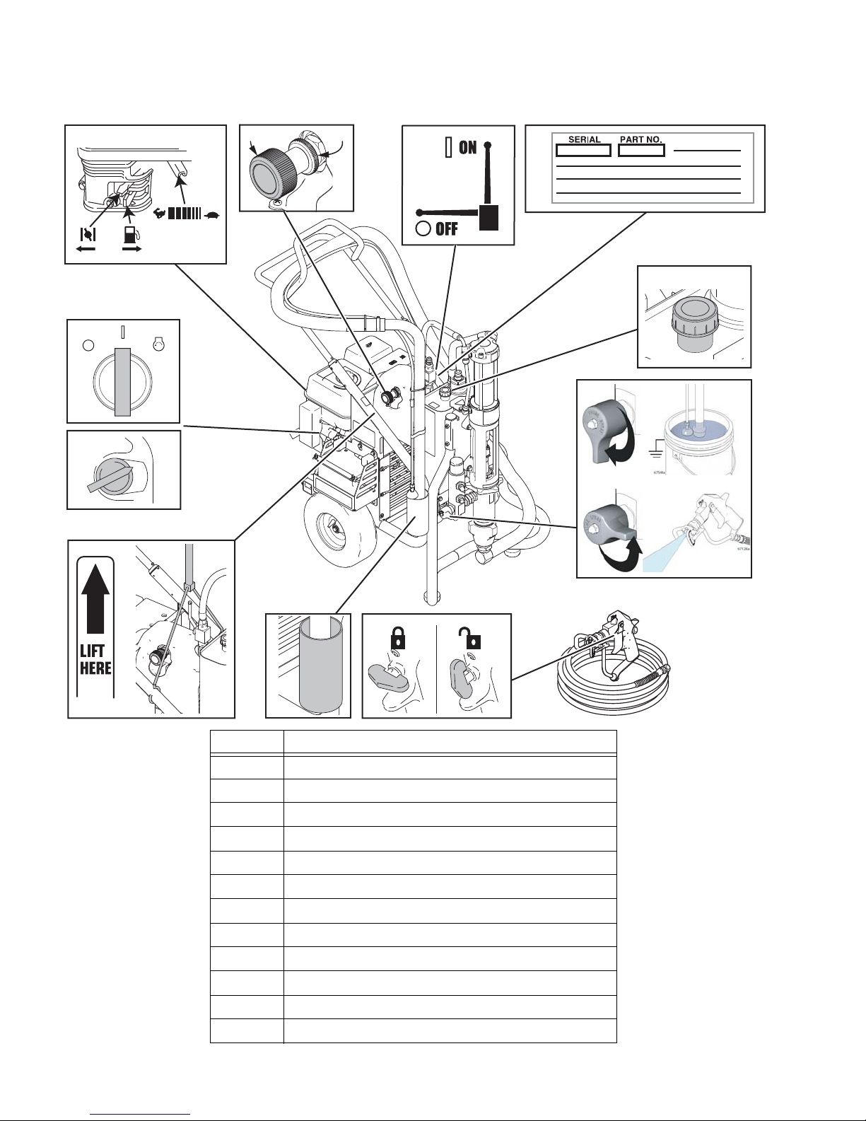
Component Identification
ON
OFF
ti21209a
2
1
3
4
56
7
12
9
10
11 8
,
Component Identification
Ref. Description
1 Engine Controls
2 Engine ON/OFF Switch (Electric-Start Models)
3 Engine ON/OFF Switch
4 Lift Location
5 Suction Holder
6 Trigger Lock
7 Drain Valve
8 Lock Ring
9 Hydraulic Pump Valve
10 Serial Number ID Label
11 Pressure Control
12 Hydraulic Oil FIll
4 311283H
Operation
OFF
ON
START
ti5261a
ti20967a
Operation
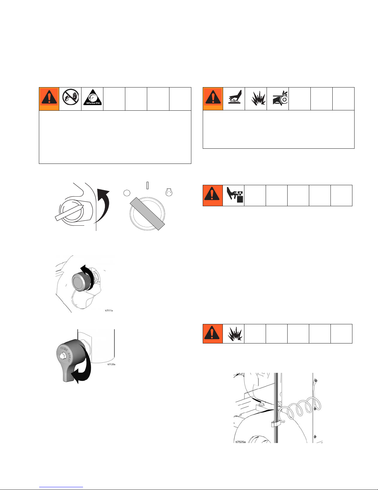
Pressure Relief Procedure
System pressure must be manually relieved to prevent
it from starting or spraying accidentally. Fluid under
high pressure can be injected into the skin and cause
serious injury. To reduce risk of injury from injection,
follow this procedure whenever you are instructed to
relieve pressure, stop spraying, service equipment or
install or clean spray tip. Read warnings, page 4.
1. Set pump valve OFF. Turn engine OFF.
2. Turn pressure to lowest setting. Trigger gun into pail
to relieve pressure.
General Repair Information
Hydraulic system and engine may become very hot
during operation and could burn skin if touched. Flam
mable materials spilled on hot, bare engine could
cause fire or explosion. Have belt guard in place during
operation to reduce risk of pinching or loss of fingers.
• Install belt guard before operation of sprayer and
replace if damaged. Belt guard reduces risk of
pinching and loss of fingers.
To reduce risk of serious injury:
• Keep all screws, nuts, washers, etc. removed during
repair procedures. These parts usually are not pro
vided with replacement kits.
• Test repairs after problems are corrected.
• If sprayer does not operate properly, review repair
procedure to verify you did it correctly. See Trou
bleshooting, page 7.
• Do not touch moving parts with fingers or tools while
testing repair.
3. Open prime valve (vertical).
If you suspect that the spray tip or hose is completely
clogged, or that pressure has not been fully relieved after
following the steps above, VERY SLOWLY, loosen tip
guard retaining nut or hose end coupling to relieve pres
sure gradually, then loosen completely. Then clean tip
and hose.
311283H 5
Grounding
Ground sprayer with grounding clamp to earth ground
for safe sprayer operation.
Maintenance
Maintenance
Spark Plug:
• Use BPR6ES (NGK) or W20EPR-U (NIPPON
DENSO) plug, only.
For detailed engine maintenance and specifications, re
fer to separate Honda Engines Owner’s Manual, sup
plied.
Frequency Procedure
Daily Check engine oil level and fill as necessary.
Daily Check hydraulic oil level and fill as necessary.
Daily Check hose for wear and damage.
Daily Check gun safety for proper operation.
Daily Check pressure drain valve for proper operation.
Daily Check and fill gas tank.
Daily Check that displacement pump is tight.
Daily Check level of TSL in displacement pump packing nut. Fill nut, if neces
sary. Keep TSL in nut to help prevent fluid build up on piston rod and
premature wear of packings and pump corrosion.
After first 20 hours
of operation
Weekly Remove engine air filter cover and clean element. Replace element, if
Drain engine oil and refill with clean oil. Reference Honda Engines
Owner’s Manual for correct oil viscosity.
necessary. If operating in an unusually dusty environment; check filter
daily and replace, if necessary.
Replacement elements can be purchased from your local Honda dealer.
• Gap plug to 0.028 to 0.031 in. (0.7 to 0.8 mm).
• Use spark plug wrench when installing and remov
ing plug.
Weekly/Daily Remove and debris or media from hydraulic rod.
After each 100
hours of operation
Semi-annually Check belt wear; replace if necessary.
Yearly or 2000
hours
6 311283H
Change engine oil. Reference Honda Engines Owner’s Manual for
correct oil viscosity.
Replace hydraulic oil and filter element with Graco ISO 46 Hydraulic Oil
169236; 5 gallon/20 liter or 207428; 1 gallon/3.8 liter) and filter element
287871.

Troubleshooting
Troubleshooting
PROBLEM CAUSE SOLUTION
Gas engine pulls hard (won't start) Hydraulic pressure is too high Turn hydraulic pressure knob coun
terclockwise to lowest setting
Gas engine does not start Switch OFF, low oil, no gasoline Consult engine manual, supplied
Gas engine doesn't work properly Faulty engine Consult engine manual, supplied
Gas engine operates, but displace
ment pump doesn't operate
Displacement pump operates, but
output is low on upstroke
Displacement pump operates but
output is low on downstroke and/or
on both strokes
Paint leaks and runs over side of wet
cup
Excessive leakage around hydraulic
motor piston rod wiper
Fluid delivery is low Pressure setting too low Increase pressure
Pump valve is OFF Set pump valve ON
Pressure setting too low Increase pressure
Displacement pump outlet filter (if
used) is dirty or clogged
Tip or tip filter (if used) is clogged Remove tip and/or filter and clean
Hydraulic fluid too low Shut off sprayer. Add fluid*.
Belt worn, broken or off Replace belt.
Hydraulic pump worn or damaged Bring sprayer to Graco distributor for
Dried paint seized paint pump rod Service pump. See manual 311485
Hydraulic motor not shifting Set pump valve OFF. Turn pressure
Piston ball check not seating properly Service piston ball check. See man
Piston packings worn or damaged Replace packings. See manual
Piston packings worn or damaged Tighten packing nut or replace pack
Intake valve ball check not seating
properly
Suction tube air leak
Loose wet-cup Tighten wet-cup enough to stop leak
Throat packings worn or damaged Replace packings. See manual
Piston rod seal worn or damaged Replace these parts.
Displacement pump outlet filter (if
used) is dirty or clogged
Intake line to pump inlet is not tight Tighten
Hydraulic motor is worn or damaged Bring sprayer to Graco distributor for
Large pressure drop in fluid hose Use larger diameter or shorter hose
Clean the filter
repair
down. Turn engine OFF. Pry rod up
or down until hydraulic motor shifts.
ual 311485
311485
ings. See manual 311485
Service intake valve ball check. See
manual 311485
age
311485
Clean filter
repair
311283H 7

PROBLEM CAUSE SOLUTION
Troubleshooting
The sprayer overheats Paint buildup on hydraulic compo
Clean
nents
Oil level is low Fill with oil.
Spitting from gun Air in fluid pump or hose Check for loose connections on
siphon assembly, tighten, then rep
rime pump.
Loose intake suction Tighten.
Fluid supply is low or empty Refill supply container.
Excessive hydraulic pump noise Low hydraulic fluid level Turn sprayer OFF. Add fluid*.
*Check hydraulic fluid level often. Do not allow it to become too low. Use only Graco approved hydraulic fluid, page 6.
8 311283H
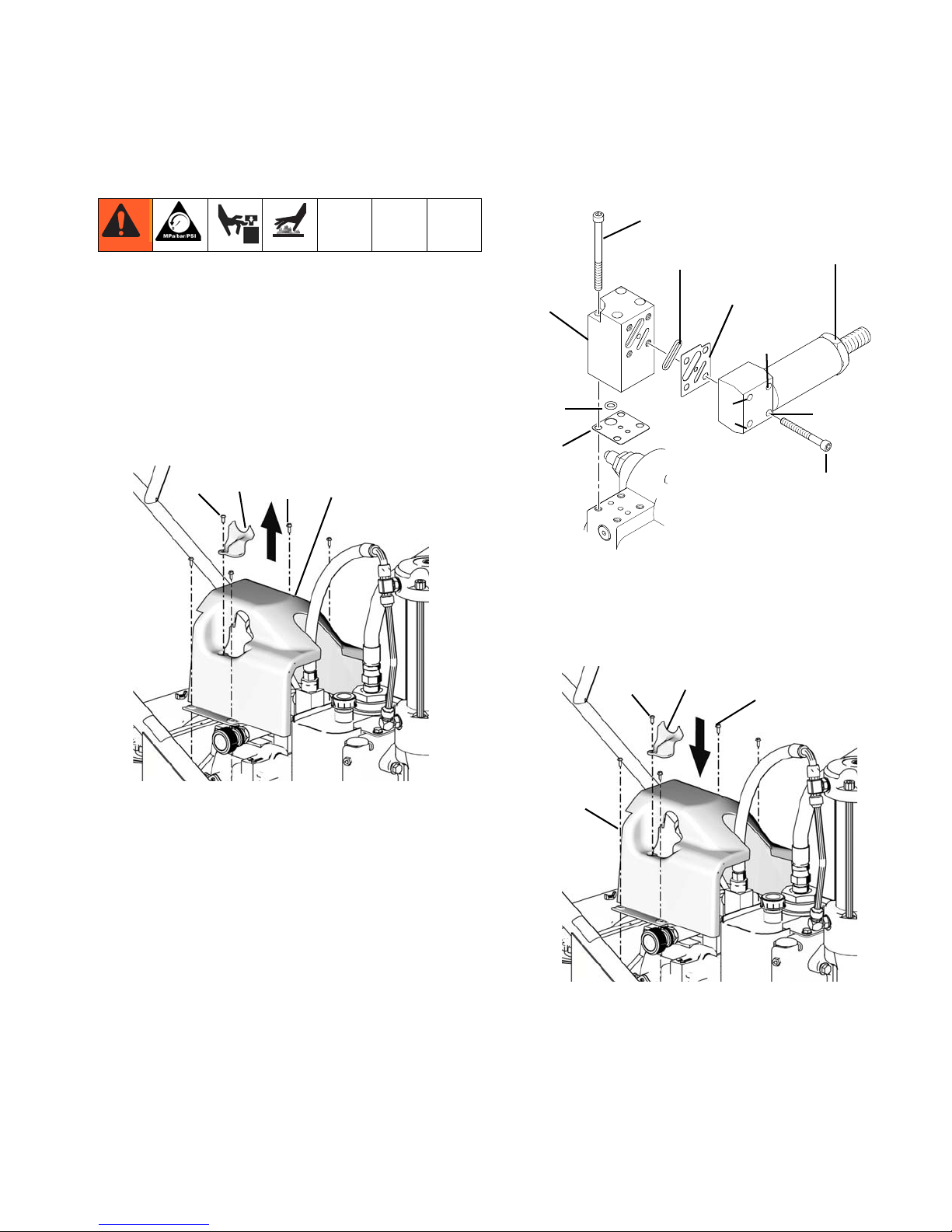
Compensator Seal Replacement
ti7805b
140
79
196
197
Torque 50 in-lbs
4 plcs
Adapter
Block
O-Ring
Gasket
O-Ring
Lubricate before installation
ti17601a
Gasket
Note Gasket Orientation
Compensator
Assembly
Torque 50 in-lbs
4 plcs
1
4
3
2
Torque sequence: 1-2-3-4-1
All cap screws must be tightened
When compensator assembled to
Gasket Adaptor Block. Do not
pre-tighten cap screws.
ti7111b
140
197
196
79
Compensator Seal Replacement
Removal
1. Relieve pressure, page 5. Allow hydraulic system to
cool before beginning the service procedure.
2. Remove screw(197) and pump handle cover (196).
Remove four cover bolts (79) and cover (140).
NOTE: It is not necessary to remove the hydraulic
lines before removing the cover. The cover is
designed to provide ample room for the cover to fit
over the hose.
4. Install new gaskets and torque screws.
5. Install cover (140) with four screws (79). Torque to
25-30 in-lb (2.8 - 3.4 N
m). Install pump handle
cover (196) with screw (197).
3. Remove compensator screws and separate com
pensator and adapter block.
311283H 9

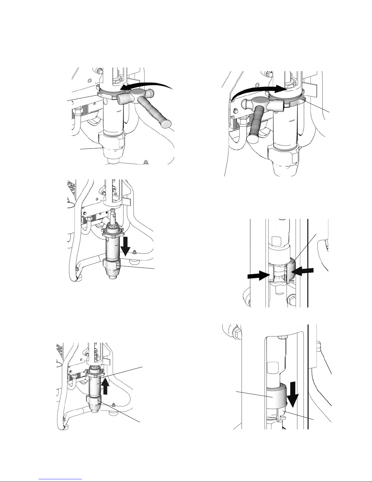
Displacement Pump Replacement
36
147
ti7119
110
121
ti7789
124
ti7816
ti7814
125
Displacement Pump Replacement
See manual 311485 for pump repair instructions.
Removal
1. Flush pump (36). Stop pump on down stroke if
possible.
2. Relieve pressure, page 5.
3. Remove suction set (147) from pump (36).
5. Remove clip (121).
6. Slide cover up (124).
4. Remove filter housing (110), page 15.
10 311283H
7. Separate coupling (125) and remove.
Displacement Pump Replacement
ti7782
122
36
ti7804
36
36
122
ti7779
ti7817
122
ti7771
125
ti7815
125
124
8. Loosen jam nut (122) with a hammer. Unscrew
pump (36) from power head.
9. Remove pump (36).
3. Hand tighten jam nut (122). Then tighten securely
1/8 to 1/4 turn with hammer or torque to 330 ft-lb
(447.4 N•m).
4. Slide cover (124) up over pump rod. With engine in
OFF position, pull recoil starter to move rod until it
contacts pump rod.
5. Install coupling (125) around pump rod.
Installation
1. Screw jam nut (122) to bottom of pump threads
(36).
2. Slide cover (124) up over pump rod. Screw pump
completely up into power head.
311283H 11
6. Slide cover (124) over coupling (125).
 Loading...