

Page 1
INSTRUCTIONS-P
This
manual contains
INSTRUCTIONS and WARNINGS.
READ AND RETAIN FOR REFERENCE.
Gas–Powered Supply Pump
ARTS LIST
IMPORTANT
307–615
Rev
S
Supersedes
R
GH 533
3000 psi (210
U.S.
Patent Pending
HYDRA–SPRA
bar) MAXIMUM WORKING PRESSURE
Model 231–533, Series B
Sprayer
only
. Has Severe–Duty* Displacement Pump
Model 230–974
Includes
RAC
*Severe–duty displacement pumps have an abrasion
and corrosion–resistant displacement rod and sleeve.
Refer
TABLE OF CONTENTS
Warnings 2.
Terms 3
Typical
Setup 4
Flushing
Operation 8
Maintenance 10
Troubleshooting 11
Service 12
Model
Model
Technical
Accessories Back
Warranty Back
Sprayer 231–533, Hose, Swivel, Gun,
IV
, DripLess
to the T
. . . . . . . . . . . . . . . . . . . . . . . . . . . . . . . . . . . . . .
. . . . . . . . . . . . . . . . . . . . . . . . . . . . . . . . . . . . . . . . . .
Installation4. . . . . . . . . . . . . . . . . . . . . . . . . . . . . . .
. . . . . . . . . . . . . . . . . . . . . . . . . . . . . . . . . . . . . . . . . .
Guidelines6. . . . . . . . . . . . . . . . . . . . . . . . . . . . . .
. . . . . . . . . . . . . . . . . . . . . . . . . . . . . . . . . . . . . .
. . . . . . . . . . . . . . . . . . . . . . . . . . . . . . . . . .
. . . . . . . . . . . . . . . . . . . . . . . . . . . . . . . . . . . . . .
230–974
231–533
Data
.
. . . . . . . . . . . . . . . . . . . . . . . . .
.
. . . . . . . . . . . . . . . . . . . . . . . . . . . .
T
ip Guard and SwitchT
echnical Data in manual 307–862.
. . . . . . . . . . . . . . . . . . . . . . . . . . . . . . . .
Parts
. . . . . . . . . . . . . . . . . . . . . . . . .
Parts
. . . . . . . . . . . . . . . . . . . . . . . . .
.
. . . . . . . . . . . . . . . . . . . . . . .
Back Cover
15.
16.
Cover
Cover
ip
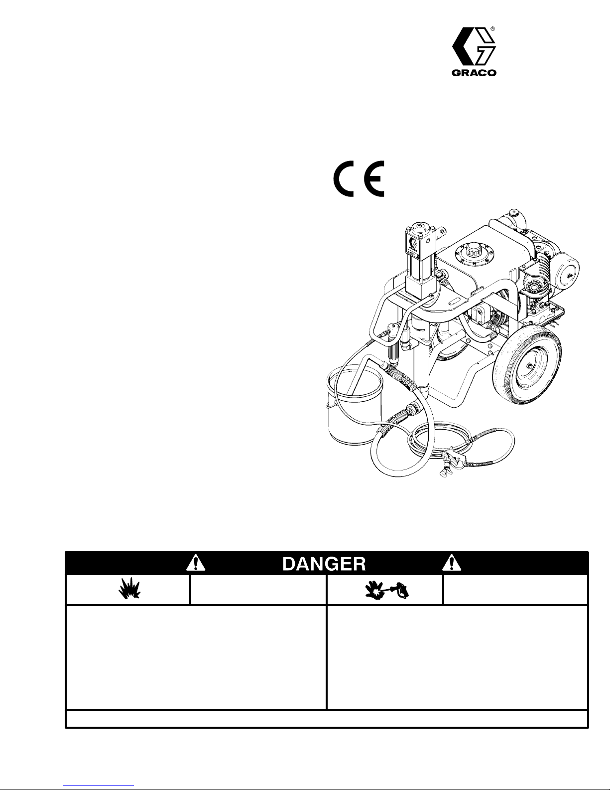
Y SPRAYER
NOTE: This
is an example of the DANGER label on your sprayer
This label is available in other languages, free of charge.
See page 20
Spray
painting,
in confined areas can result in fire or explosion.
uids
Use
outdoors or in extremely well ventilated areas. Ground
hoses, containers and objects being sprayed.
ment,
Avoid
all ignition sources such as
cloths,
open flames
arcs from connecting or disconnecting power cords or turn
rettes,
light switches on and off.
ing
Failure
to follow this warning can result in death or serious injury
flushing or cleaning equipment with flammable liq
to order.
static electricity from plastic drop
such as pilot lights, hot objects such as ciga
READ AND UNDERSTAND ALL LABELS AND INSTRUCTION MANUALS BEFORE USE
GRACO
FIRE
AND
EXPLOSION HAZARD
equip
INC.P.O. BOX 1441
COPYRIGHT 1983 GRACO INC.
.
SKIN INJECTION
HAZARD
Liquids
-
-
-
-
.
MINNEAPOLIS, MN
can be injected into the body by high pressure airless spray
or
leaks – especially hose leaks.
Keep
body clear of the nozzle. Never stop leaks with any part of the
body.
Drain all pressure before removing parts.A
of gun by always setting safety latch when not spraying.
gering
Never spray without a tip guard.
In case of accidental skin injection, seek immediate
“Surgical
Failure to follow this warning can result in amputation or serious
injury.
T
reatment”.
void accidental trig
55440–1441
-
Page 2

HIGH
OBSER
PRESSURE SPRA
VE ALL W
ARNINGS.
Y CAN CAUSE SERIOUS INJURY. FOR PROFESSIONAL USE ONL
FLUID INJECTION HAZARD
WARNINGS
Y.
Read and understand all instruction manuals before operating equipment.
General
This
the
your
ily
or
age.
NEVER
NEVER put hand or fingers over the spray tip. NEVER try to
“blow back” paint, this is NOT an air spray system.
ALWA
ALWAYS
cleaning or removing the spray tip or servicing any system
equipment.
NEVER
Be
each
Medical
If any fluid appears to penetrate your skin, get EMERGENCY
MEDICAL CARE AT ONCE. DO NOT TREAT AS A SIMPLE
CUT.
Note
It
sible. Do not delay treatment to research toxicity. Toxicity is
a
blood stream. Consultation with a plastic surgeon or reconstructive
Spray T
Use extreme caution when cleaning or changing spray tips. If
the
immediately. ALWAYS follow the Pressure Relief Procedure
and
Safety
equipment generates very high fluid pressure. Spray from
gun, leaks or ruptured components can inject fluid through
skin and into your body
injury
, including the need
splashed into the eyes or
point the spray gun at anyone or at any part of the body
YS have the tip guard on the spray gun when spraying.
follow the Pressure Relief Procedure
try to stop or deflect leaks with your hand or body
sure equipment safety devices are operating properly before
use.
Alert––Airless Spray W
T
ell the doctor exactly what fluid was injected.
to Physician
is important to treat the injury surgically as soon as pos
concern with some exotic coatings injected directly into the
hand surgeon may be advisable
and cause extremely serious bod
for amputation. Also, fluid injected
on the skin can cause serious dam
, below
, before
.
ounds
:
Injection in the skin is a traumatic injury
.
ip Safety
spray tip clogs while spraying, engage the gun safety latch
then remove the spray tip to clean it.
NEVER
fully
Spray
Be sure all gun safety devices are operating properly before
each
cause
Safety Latch
.
Whenever you stop spraying, even for a moment, always set
the
gun
dental
Diffuser
The gun diffuser breaks up spray and reduces the risk of fluid
injection
regularly. Follow the Pressure Relief Procedure , below .
Remove
gun
the gun. If the fluid emitted
stream,
T
ALWAYS
The
reduce, but does not prevent, the risk of accidentally placing
your
T
.
Always
-
ing to reduce the risk of accidentally triggering the gun if it is
dropped
wipe of
relieved and the gun safety latch is engaged.
f build–up around the spray tip until pressure
Gun Safety Devices
use. Do not remove or modify any part of the gun, this can
a malfunction and result in serious bodily injury
gun safety latch in
inoperative. Failure to set the safety latch can result in acci
triggering of the gun.
when the tip is not installed. Check dif
the spray tip. Aim the gun into a metal pail, holding the
firmly to the pail. Using the lowest possible pressure, trigger
replace the dif
ip Guard
have the tip guard
tip guard alerts you to the fluid injection hazard and helps
fingers or any part of your body close to the spray tip.
rigger Guard
have the trigger guard in place on the gun when spray
or bumped.
the closed or “safe” position, making the
is not
fuser immediately
in place on the gun while spraying.
diffused into an irregular
.
MOVING PARTS HAZARD
Moving
parts
parts.
the sprayer
checking or servicing the sprayer to prevent it from starting
fore
accidentally.
can pinch or amputate your fingers or other body
KEEP CLEAR of moving parts when starting or
. Follow the
Pressure Relief Procedure
is
.
fuser operation
operating
, below
, be
-
-
-
Pressure
To
reduce the risk of serious bodily injury
jection,
or
injury from moving parts or electric shock, follow this pro
cedure
any part of
tips,
1.
2. Open the bypass valve.
3.
4.
Relief Procedure
splashing fluid or solvent in the eyes or on the skin,
whenever you shut of
the
and whenever you stop spraying.
Engage the gun safety latch.
Depress the engine stop button.
Close the fuel shutof
spray system, install, clean or change spray
f the sprayer
f valve.
4
1,6
2
, including fluid in
, check or service
5. Disengage
-
-
3
gun
ger
6.
Engage the gun safety latch.
7. Open the pressure drain valve, having a container
ready
you
If you suspect that the spray tip or hose is completely
clogged,
the steps above,
lowing
retaining
ally,
then loosen completely
the gun safety latch. Hold a metal part of the
firmly to the side of a
the gun to relieve pressure.
to catch the drainage. Leave the valve open until
are ready to spray again.
or that pressure
nut or hose end coupling to
5
grounded metal pail, and trig
has not been fully relieved after fol
VER
Y SLOWL
. Now clear the tip or hose.
Y loosen the tip guard
relieve pressure gradu
7
-
-
-
Page 3
EQUIPMENT MISUSE HAZARD
General
Misuse
zing,
or
in
fluid injection, splashing on the eyes or skin,
bodily
NEVER alter or modify any part of this equipment, doing so
could
CHECK all spray equipment regularly and repair or replace
worn
Always
ing and respirator as recommended by the fluid and solvent
manufacturer.
System
This sprayer can develop
WORKING
accessories
exceed
system.
Fluid and Solvent Compatibility
BE
patible
on page 20. Always read the fluid and solvent manufacturer ’s
literature
Do
logenated hydrocarbon solvents or fluids containing such solvents in this equipment, which contains aluminum and/or zinc
parts.
the possibility of explosion, which could cause death, serious
bodily
Safety
of the equipment or accessories, such as overpressuri
modifying parts, using incompatible chemicals and fluids,
worn or damaged parts,
injury
, or fire, explosion or property damage.
cause it to malfunction.
or damaged parts immediately
wear ear protection, protective
can cause them to rupture and result
Pressure
PRESSURE
used are rated to withstand this pressure. DO NOT
the maximum working pressure of any part used in the
SURE that all
with the wetted parts shown in the
before using them in this sprayer
not use 1,1,1-trichloroethane, methylene chloride, other ha
Such
injury and/or substantial property damage.
fluids and solvents used are chemically com
use could result in a serious chemical reaction, with
3000 psi (195 bar) MAXIMUM
.
Be sure that all
HOSE SAFETY
High
pressure fluid in the hoses can
hose develops a leak, split or rupture due to any kind of wear,
damage
cause a fluid injection injury or other serious bodily injury or
property
All
spring guards help protect the hose from kinks or bends at or
close
TIGHTEN
pressure
sure
NEVER
tire
movement of the hose couplings. If
ist, replace the hose immediately
pressure hose or mend it with tape or any other device. A repaired
HANDLE AND ROUTE HOSES CAREFULLY. Do not pull on
hoses to move equipment. Keep hoses clear of moving parts
and
or solvents which are not compatible with the inner tube and
cover
above
Hose Grounding Continuity
Proper
grounded
fluid
tag on it which specifies the maximum electrical resistance,
contact
sistance
for your hose to check the resistance. If the resistance exceeds
the recommended limits, replace it immediately . An ungrounded
ardous.
or misuse, the high pressure spray emitted from it
damage.
fluid hoses must have spring guards on both ends!
to the coupling which can result in hose rupture.
all fluid connections securely before each use. High
fluid can dislodge a loose coupling or allow high pres
spray to be emitted from the coupling.
use a damaged hose. Before each use, check the en
hose for cuts,
hose cannot contain the high pressure fluid.
hot surfaces of the pump and gas engine. Do not use
of the hose. DO NOT
180F (82C) or below –40F (–40
hose grounding continuity is essential to maintaining a
spray system. Check the electrical resistance of your
hoses at least once a week. If your hose does not have a
the hose supplier or manufacturer for the maximum re
limits. Use a resistance meter in the appropriate range
or poorly grounded hose can make
Also read
leaks, abrasion, bulging cover
. DO NOT try to recouple high
expose Graco hose to temperatures
FIRE OR EXPLOSION HAZARD.
or other serious
.
eyewear
be very dangerous. If the
any of these conditions ex
, gloves, cloth
spray equipment and
TECHNICAL DATA
.
can
The
, or damage or
fluids
C).
your system haz
FIRE OR EXPLOSION HAZARD
Static
electricity is created by the flow of fluid through the pump
and hose. If all spray equipment is not properly grounded,
-
sparking may occur and the system may become hazardous.
Sparking
cord. Sparks can ignite fumes from solvents, the fluid being
sprayed, dust particles and other flammable substances,
whether
explosion and serious bodily injury and property damage.
If you experience any static sparking or even a slight shock
while
Check the entire system for proper grounding. Do not use the
system again until the problem has been identified and corrected.
-
may also occur when plugging or unplugging a power
spraying indoors or outdoors, and
using this equipment, STOP SPRA
can cause a fire or
YING IMMEDIA
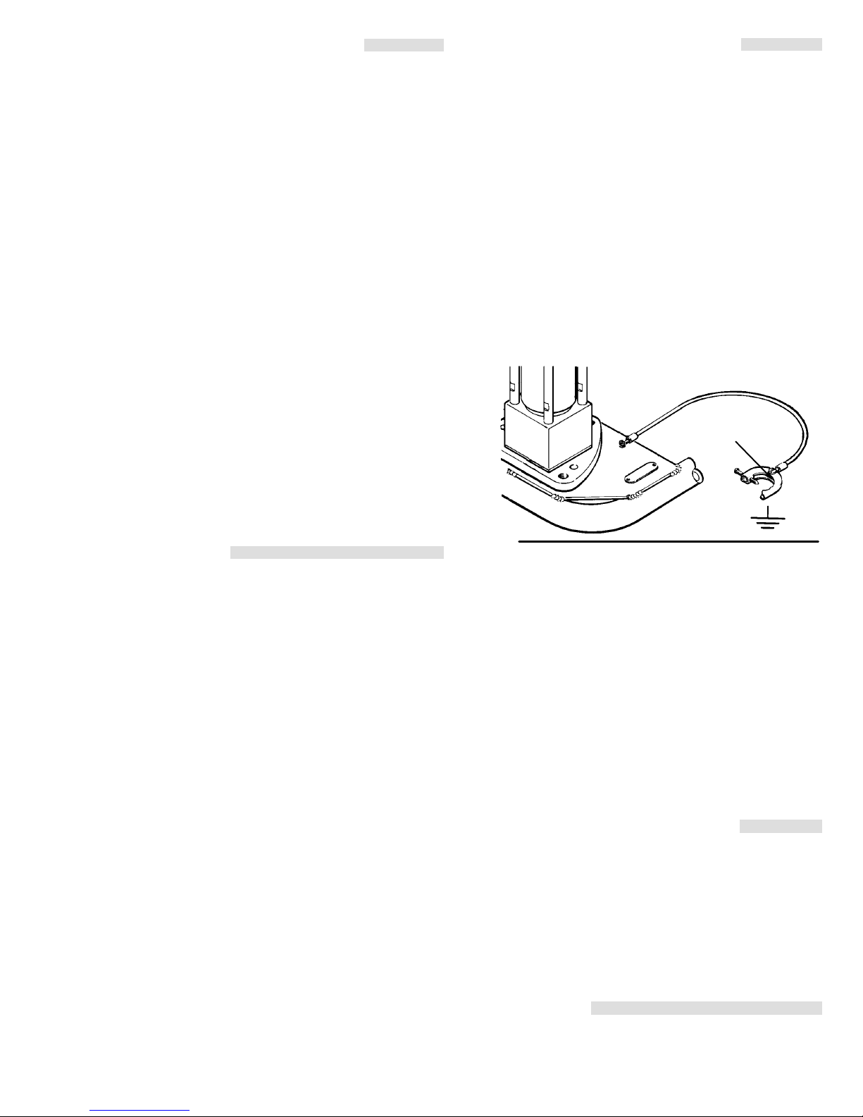
Grounding
To
reduce the risk of static sparking, ground the sprayer and
other spray equipment used or located in the spray area.
CHECK
tions
all
1.
-
-
2.
3.
4.
5.
6.
7.
-
-
Flushing
Reduce the risk of fluid injection injury , static sparking, or
splashing
manual.
your local electrical code for
for your area and type of equipment. BE SURE to ground
of this spray equipment:
Sprayer:
a
true earth ground. See Fig 1.
Fig
1
Fluid hoses:
150
ity.
Spray
erly
Object being sprayed:
Fluid supply container:
connect the ground wire and clamp (provided) to
m combined hose length to ensure grounding continu
See
grounded fluid hose and sprayer
use only grounded hoses with a maximum of
Hose Grounding Continuity.
gun:
obtain grounding through connection
according to local code.
according to local code.
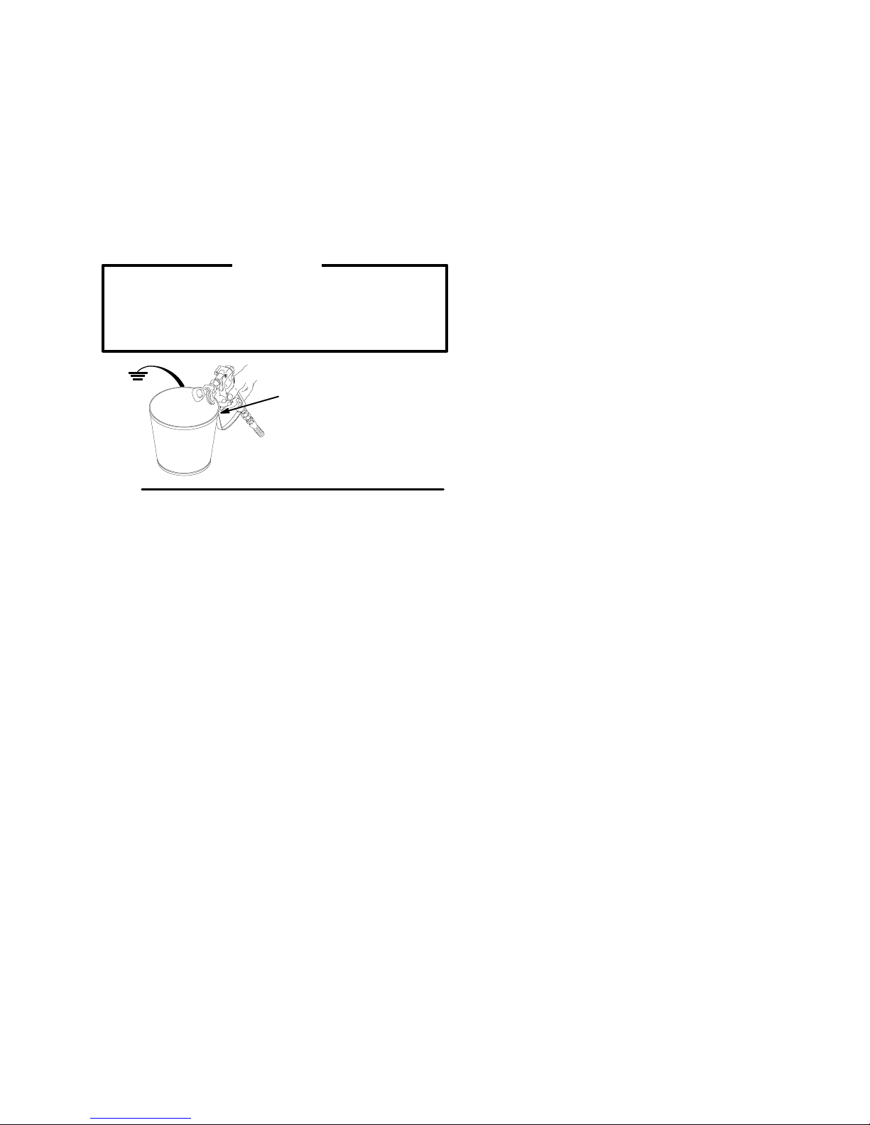
All solvent pails used when flushing,
code. Use only metal pails, which are conductive. Do not
the pail on a non–conductive surface, such as
place
or
cardboard, which interrupts the grounding continuity
To
maintain grounding continuity when
pressure
side
, always hold a metal part of the gun firmly to the
of a grounded metal pail, then trigger the gun.
detailed grounding instruc
CLAMP
.
according to local
flushing or relieving
Safety
by following the flushing procedure
on page 6 of this
GASOLINE ENGINE HAZARDS
NEVER
spilled on a hot surface can ignite and cause a fire. AL WAYS
pour
NEVER operate the engine in a closed building unless the
engine
monoxide, a poisonous, odorless and invisible gas which can
cause
NEVER alter the throttle setting which is factory set at the
maximum
this
-
IMPORTANT
United States Government safety standards have been
adopted
-
standards – particularly the General Standards, Part 1920 and
the
fill the fuel tank while the engine is running or hot. Fuel
fuel in slowly to avoid spilling.
exhaust is piped outside. The exhaust contains carbon
serious illness and even death if inhaled.
full load engine speed of 2800 RPM. T
can change the sprayer and will void the warranty
under the Occupational Safety and Health Act. These
Construction Standards, Part
1926 – should be consulted.
TELY.
all
to a prop
paper
.
ampering with
.
-
-
-
Page 4
TERMS
WARNING: Alerts user to avoid or correct conditions
could cause bodily injury
that
.
CAUTION: Alerts user to avoid or correct conditions
could damage or destroy equipment.
that
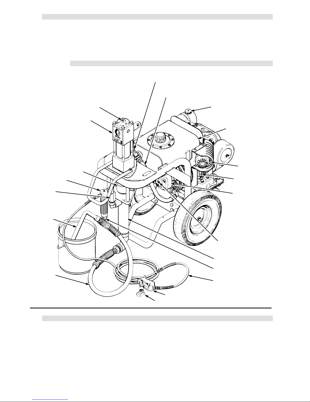
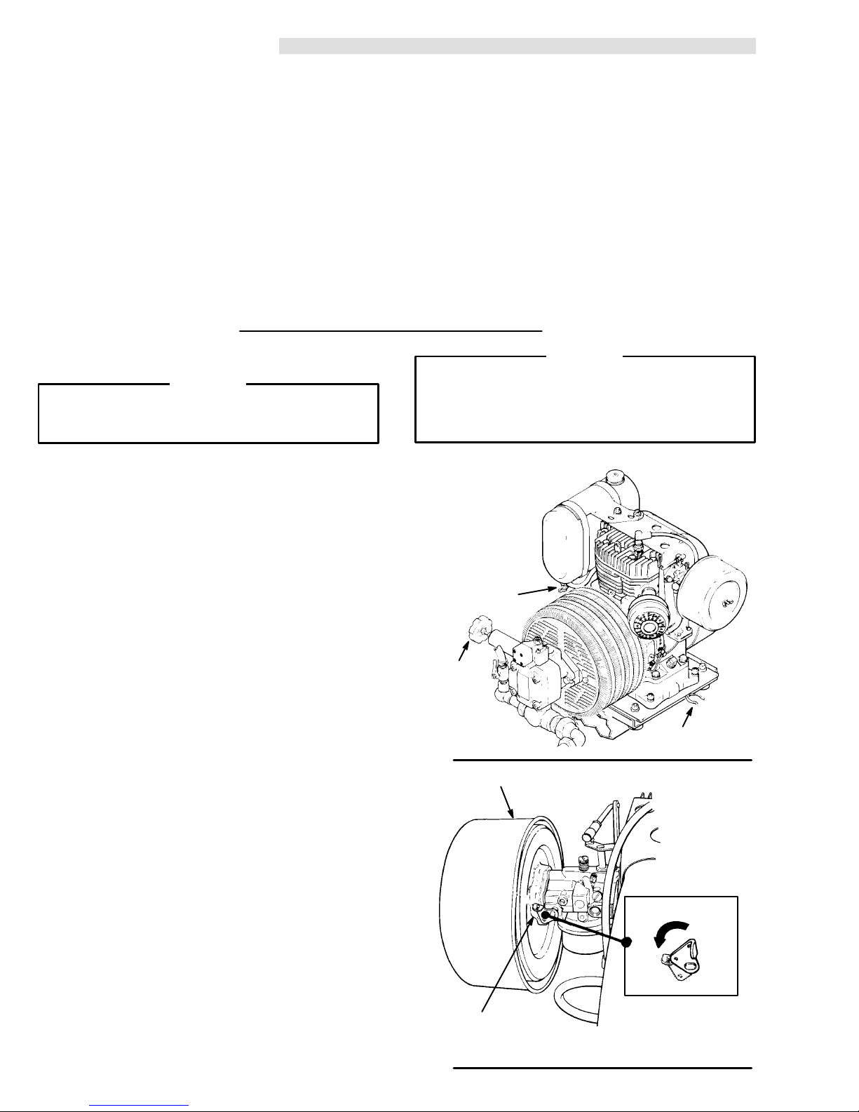
INSTALLATION
MOTOR RESET BUTTON
HYDRAULIC MOTOR
PACKING NUT/WET–CUP
NOTE: Identifies
essential procedures
mation.
HYDRAULIC RETURN LINE TO MOTOR
HYDRAULIC SUPPLY LINE TO MOTOR
GASOLINE FILL CAP
or addition infor
HYDRAULIC
RESERVOIR
MUFFLER
-
CHECK VALVE
SUCTION TUBE
SUCTION HOSE
Fig
2
SETUP
FILTER
STOP BUTTON
HYDRAULIC
PUMP
PRESSURE
CONTROL KNOB
DISPLACEMENT PUMP
PRESSURE DRAIN VALVE
SPRAY HOSE
SILVER GUN
RAC IV DripLess TIP GUARD
1. Connect the Hose and Gun
a.
Remove the plastic cap plug from
and screw an accessory, conductive or
grounded
nipple.
b. Connect a small diameter
spray hose onto the 1/4 npsm(f) outlet
See Fig 2.
, 3 ft (0.9 m) whip hose
between the main hose and a spray gun, if desired, for more flexible gun movement. See Fig
2.
307-615
4
the outlet tee
c. Don’t
use thread sealant on the swiveling nut of
the
hose couplings, and
don’
t install the spray
tip yet.
NOTE: Use
thread
sealant on all male threads except at
swivel unions. Swivel unions are made to self–
seal, and using thread sealant prevents the
swivel
from turning freely
.
2. Fill the Packing Nut/W et Cup 1/3 full with Graco
Throat
Seal Liquid (TSL), supplied. See 2
.
Page 5
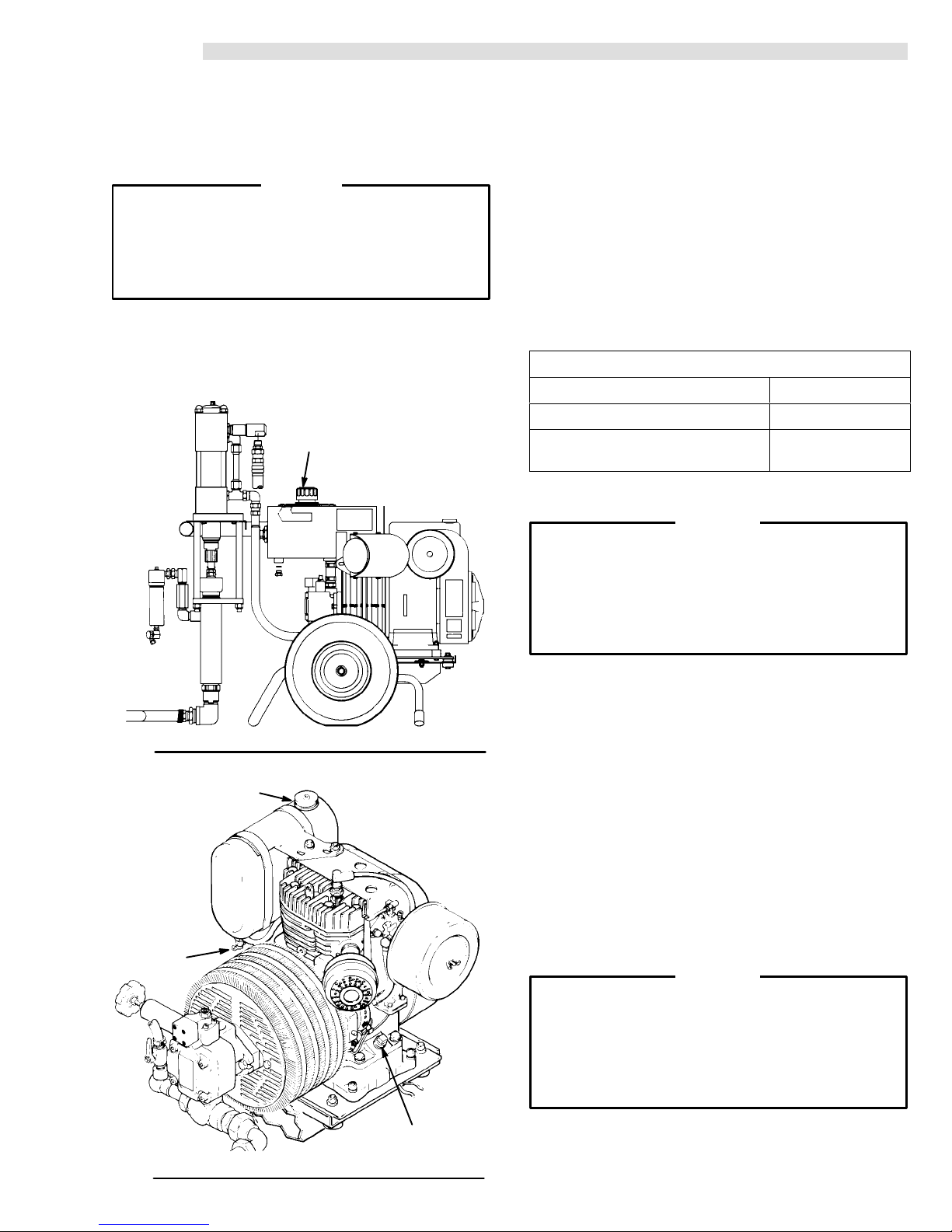
SETUP
3.
Check the Hydraulic Oil Level
4. Check
the Engine Oil Level
a. Unscrew the oil fill cap. See Fig 3. The dipstick
attached to the cap.
is
full
line on the dipstick.
The oil should be up to the
CAUTION
To prevent damage to the cooling system and
hydraulic
pump, use
only
Graco Hydraulic Oil,
part
no. 169–236 (5 gal./20 liter) or part no. 207–428 (1
gal/3.8 liter). Other types of hydraulic oil may
damage
the hydraulic components.
b. Add oil as needed to the proper level. A
completely full hydraulic system contains about
gallons (20 liters) of oil.
5
HYDRAULIC OIL FILL CAP
a. Unscrew
is
attached to the plug.
the oil fill plug. See Fig 4. The
dipstick
b. Without threading the plug into place, check to
be sure the oil is up to the top mark on the
dipstick.
c. If oil is needed, see the chart below for the
recommended
d.
Crank case capacity: 2 quarts (1.9 liters)
RECOMMENDED LUBRICA TION OIL:
oil type and weight.
Use a high
quality, detergent oil classified FOR SERVICE SD OR
for regular use and for breaking in a new engine.
SE
GRADE OF OIL CHART
SEASON OR TEMPERA
Spring, Summer
30
F to 0
TURE
, Autumn
GRADE OF OIL
SAE 30
SAE 10W–30
Winter
5. Fill the Fuel Tank
WARNING
Fuel spilled on a hot surface can cause a fire or
explosion
and cause
serious bodily injury and prop
erty damage. Always shut off the engine and let it
cool before filling the tank, and carefully follow
steps
5.a. to 5.c.,
below
, being sure not to spill any
fuel.
Fig 3
GASOLINE FILL CAP
FUEL
SHUTOFF
VALV E
a. Close
the fuel tank valve. See Fig 4.
b. Use only clean, fresh, well-known brands of
unleaded
octane
and
c. Remove
regular grade gasoline
. The minimum
requirements are 86 octane in the U.S.A.
96 octane elsewhere.
the fuel fill cap and fill the tank. Be sure
the air vent in the fill cap is not plugged so fuel
flow to the carburetor
can
See
Fig 4.
d.
Fuel tank capacity: 1.5 gallons (6 liters)
, then
replace the cap.
e. Gasoline consumption at the maximum oper-
ating speed of 2800 RPM is about 1.3 gallons/
(4.9 liters/hour).
hour
6. Grounding
WARNING
To reduce the risk of static sparking, fire or explosion which can result in serious bodily injury and
property damage, always ground the sprayer , all
system
components, and the object being sprayed
as instructed under FIRE OR EXPLOSION
HAZARD
on page 3.
Fig
4
ENGINE OIL
FILL PLUG
7. Flush the sprayer to remove the oil which was left
the pump after factory
in
testing to protect the pump
from corrosion. See Flushing Guidelines on page
6.
Page 6
FLUSHING GUIDELINES
When to Flush
1. New sprayer. Your new sprayer was factory tested
with
lightweight oil which was left in to protect pump
parts
from corrosion.
Before using oil–base paint,
only
spirits
Before
.
using water–base paint,
flush with mineral
flush with
mineral
spirits, followed by soapy water, then a clean water
rinse.
2. Changing colors. Flush with a compatible solvent
as mineral spirits.
such
3. Changing from water–base to oil–base paint.
with soapy water
Flush
, then mineral spirits.
How to Flush
WARNING
Follow the Pressure Relief Procedure W arning
page 8. Remove the spray tip before flushing.
on
1. Engage the gun safety latch. Remove the spray tip
the gun.
from
4. Changing from oil–base to water–base paint.
Flush with mineral spirits, followed by soapy water ,
a clean water flush.
then
5. Storage.
Water–base paint:
and leave the pump, hose and gun filled with
spirits
flush with water , then mineral
mineral spirits. Follow the Pressure Relief Proce-
W
dure
arning,
Oil–base
Pressure
6.
Startup after storage.
Before using water–base paint,
with soapy water and then clean water
spirits
When using oil–base paint,
with fluid to be sprayed.
spirits
page 8.
paint:
flush
with mineral spirits. Follow the
Relief Procedure W
arning
, page 8.
flush out mineral
.
flush out mineral
WARNING
Always
recoiling
jured
starter
hold the starter rope firmly while pulling or
it to reduce
the chance of being hit and in
by the rope or of jamming and damaging
assembly
.
the
-
2. Pour enough clean, compatible solvent to fill the
and hoses into a large, grounded metal pail.
pump
3. Place
the suction tube into the pail or tilt the sprayer
back
(it will support
itself) and place the pail under the
pump. Then tilt the sprayer forward to lower the
into the pail.
pump
4. Turn the pressure control knob
until
all spring tension is relieved. Y
feel
it. The sprayer is now set at the lowest pressure
counterclockwise
ou will be able to
setting. T urning the knob further will remove it.
Tighten
the knob locknut to set. See Fig 5.
5. Open the bypass valve. The valve lever will be
parallel
to the body of the valve. See 5.
6. Open the fuel shutoff valve by screwing it out as far
as it will go. See 5.
7. Disengage
See
8. Close
(horizontal). See Fig 6.
tion
9. Brace
the starter
pulling
the foot brace from the hitch and lower it.
Fig 5.
the choke by turning the lever to the ON posi
one foot against the foot brace and gently pull
rope
until you feel it engage, the continue
all the way out
and let it recoil slowly into the
starter. Then, holding the starter rope firmly, rapidly
the rope to
pull
one or two attempts, open the choke a little (turn
ter
start the engine. If it does not start af
lever toward OFF position). If the engine floods,
the choke all the way and continue pulling the
open
rope.
-
-
SHUTOFF
PRESSURE
CONTROL
KNOB
Fig 5
AIR FILTER
CHOKE
Fig
6
FUEL
VALV E
HITCH
OFF
ON
TO CLOSE CHOKE,
TURN TO THE ON
POSITION
(HORIZONTAL)
Page 7
How to Flush (continued)
10.
Raise the foot brace and engage it in the hitch.
11. After the engine is warm, gradually open the choke
lever (turn to OFF position) and close the bypass
See Fig 5 and 6.
valve.
12. Point the gun into the grounded metal pail and hold
metal part of the gun firmly against the pail.
a
NOTE: To save the fluid in the pump and hose, trigger
the gun into the paint container or a separate
clean
container. At the same time, slowly turn the
pressure control knob clockwise just enough to
start the pump. When solvent appears, release
the
trigger and continue as below
.
WARNING
To reduce the risk of static sparking and splashing
flushing, always remove the spray tip from the
when
gun
and hold a metal part of the gun firmly to the side
of
a grounded metal pail.
13. Making firm metal-to-metal contact, hold the gun
to the side of the grounded solvent pail. T
firmly
rigger
the gun. At the same time, slowly turn the pressure
control
knob clockwise just enough to start the
pump.
14. Circulate the solvent until the system is thoroughly
flushed.
15. Release
16. If
you are going to start spraying,
or
Pressure
the trigger and engage the gun safety
suction tube into the supply container
Relief Procedure
place the pump
on page 2. Engage
latch.
. Follow the
the
gun safety latch until you are ready to prime the
See Step 3, page 9.
pump.
17. If
you are going to store the sprayer, be sure your
final flush is with an oil–based solvent, such as
mineral spirits. Remove the suction tube or pump
from the solvent pail. Follow the Pressure Relief
Procedure
but
leave the drain valve open.
on page 2. Engage the gun safety latch,
Fig 7
MAINTAIN
METAL-TO-METAL
CONTACT
AND GROUNDED PAIL
FIRM
BETWEEN GUN
Page 8

OPERATION
WARNING
Pressure Relief Procedure
To
reduce the risk of serious bodily injury, including
fluid
injection, splashing fluid or solvent in the eyes
or
on the skin, or injury from moving parts or electric
shock,
follow this procedure whenever you shut of
sprayer
the
, check or service any part of the spray
system, install, clean or change spray tips, and
whenever
1.
2.
3.
4.
5. Disengage the gun safety latch. Hold a metal
you stop spraying.
Engage the gun safety latch.
Open the bypass valve.
Depress the engine stop button.
Close the fuel shutof
of the gun
part
f valve.
firmly to the side of a grounded
metal pail, and trigger the gun to relieve pressure.
6. Engage
the gun safety latch.
7. Open the pressure drain valve, having a container ready to catch the drainage. Leave the
open until you are ready to spray again.
valve
If you suspect that the spray tip or hose is com-
clogged, or that pressure has not been fully
pletely
relieved
around
pling
after following the steps above,
wrap a rag
the tip guard retaining nut or hose end cou
and VER
Y SLOWL
Y loosen the part to
relieve
pressure gradually, then loosen completely . Now
the tip or hose.
clear
f. Brace
one foot against the foot brace and gently
pull the starter rope until you feel it engage, the
continue pulling all the way out and let it recoil
slowly into the starter. Then, holding the starter
rope firmly, rapidly pull the rope to start the en-
If it does not start after one or two attempts,
gine.
f
open
the choke a little (turn lever toward OFF po
-
sition). If the engine floods, open the choke all
way and continue pulling the rope.
the
WARNING
Always
recoiling
jured
starter
hold the starter rope firmly while pulling or
it to reduce
the chance of being hit and in
by the rope or of jamming and damaging
assembly
.
-
the
g. After the engine is warm, gradually open the
choke
lever (turn to OFF position)
bypass
h.
Raise the foot brace and engage it in the hitch.
-
SHUTOFF
valve. See Fig 8 and 9.
FUEL
VALV E
and close the
AIR FILTER
Prepare the Fluid
1.
a. Prepare
turer’s
b. Place
the fluid according to the fluid
recommendations.
the pump
or suction tube into the fluid con
tainer.
2. Starting
the Sprayer
a. Open the bypass valve to make startup easier .
the open position, the valve lever is parallel to
In
the
body of the valve. See Fig 8. Close the
drain
valve.
b. Turn the pressure control knob
until all spring tension is relieved. Y ou will
wise
be able to feel it. The sprayer is now set at the
pressure setting. T
lowest
will
cause it to fall of
c. Open
the fuel shutof
far
as it will go. See Fig 8.
urning the knob further
f.
f valve
by screwing it out as
d. If the engine is cold, close the choke by turning
lever to the ON position
the
(horizontal). See Fig
9.
e. Disengage the foot brace from the hitch and
lower
307-615
8
it. See FIg 8.
manufac
filter
counterclock-
-
-
PRESSURE
CONTROL
KNOB
BYPASS
Fig 8
Fig
VALV E
AIR FILTER
CHOKE
9
HITCH
STOP BUTTON
OFF
ON
TO CLOSE CHOKE,
TURN TO THE ON
POSITION
(HORIZONTAL)
Page 9

NOTE: In cold weather , run the engine for about 15
minutes with the bypass valve open before
starting the displacement pump, to help avoid
hydraulic
motor stalling.
i. Follow the Pressure Relief Procedure
Warning
on page 8, to shut of
f the sprayer
.
WARNING
To stop the engine in an emergency , depress
the engine ST OP button. Close the bypass valve
if possible. See Fig 8. Then follow the Pressure
Procedure W
Relief
arning
on page 8.
If the motor stalls during operation, depress the
engine stop buttonturn OFF the ON/OFF switch. With
hand, firmly press straight down on the motor reset
your
button. Now try to restart the sprayer . If it will not start,
to the separate motor manual, 307–158.
refer
CAUTION
Never use a hammer to depress the reset button,
as
it could cause serious internal motor damage.
3.
Prime the Pump
a.
Be sure the gun safety latch is engaged.
b.
Don’t install the spray tip yet!
c. If the engine has not been started, follow the
procedure
d.
Disengage the gun safety latch.
e. Point
a
metal part of the gun
the WARNING below
f. Squeeze
control knob
pump.
g. Operate
in Step 2, page 8.
the gun into a grounded metal pail and hold
firmly
against the pail. See
.
the trigger and
clockwise
slowly
turn the pressure
just enough to start the
See Fig 8.
the pump until all air is purged from the
pump and hoses and the fluid is flowing freely
the gun.
from
h. Release
i. Turn the pressure control knob
wise
be
the trigger and engage the safety
counterclock-
until all spring tension is relieved. Y ou will
able to feel it. The sprayer is now at the
lowest
latch.
pressure setting. T urning the knob further will
remove
j. Follow
it.
the
Pressure Relief Procedure
on page
8. Then install the spray tip in the gun as
instructed in the separate gun or tip instruction
manual. If you are using the RAC IV supplied
this sprayer
with
, see manual 307–848.
MAINTAIN
METAL-TO-METAL
CONTACT
AND GROUNDED PAIL
FIRM
BETWEEN GUN
b. Always use the lowest pressure that is neces-
to completely atomize the fluid.
sary
CAUTION
Operating the sprayer at a higher pressure than
necessary
shortens
the sprayer life.
wastes fluid, causes early
tip wear
c. If more coverage is needed, use a larger tip
than increasing the pressure.
rather
d. Check
the
spray pattern. The tip size and angle
determines the pattern width and flow rate. See
the
separate manual received with your gun.
CAUTION
The engine throttle has been set and locked at
2800 RPM. The sprayer warranty will be voided
the hydraulic pump life shortened
and
is changed.
ment
if this adjust
5. Cleaning a Clogged Tip
WARNING
reduce the risk of a fluid injection injury
To
, NEVER
hold your hand, body or a rag in front of the spray
tip when cleaning or checking for a cleared tip. To
reduce the risk of a fire or explosion, always hold
gun firmly against the side of a grounded metal
the
waste
container when checking to see if the tip was
cleared
or when using a self–clearing tip.
a. Follow the Pressure Relief Procedure
Warning
on page 8.
b. Clean the front of the tip frequently during the
day to keep the fluid from building up and clog-
the tip. T
ging
refer
to your separate gun
o clean, and to clear a tip if it clogs,
instruction manual. If
you are using the RAC IV tip guard and
SwitchTip,
6.
Shutting Off the Sprayer
refer to manual 307–848.
a. Whenever you stop spraying, even for a short
break, follow the Pressure Relief Procedure
Warning
on page 8.
b. Clean the tip and gun as recommended in your
separate
c. Flush
gun or tip manual.
the sprayer at the end of each
work day if
using water–based fluid or if it could harden in
sprayer over night. See
the
FLUSHING
LINES, page 6. Use a compatible solvent to
flush, then fill the pump and hoses with solvent
such as mineral spirits to help prevent pump
corrosion.
Relieve pressure!
d. For long term shutdown or storage,
sprayer with mineral spirits to prevent
the
corrosion.
Relieve pressure!
, and
GUIDE
always
pump
-
-
fill
Fig 10
4. Adjusting
the Pressure
a. Turn the pressure control knob
increase and
pressure. T
counterclockwise
ighten the knob locknut to set.
clockwise
to
to decrease the
7. Adjusting the Intake V
The pump is set to handle
a.
viscosity
fluid. T
o adjust
or heavier viscosity fluid, disassemble the
valve as instructed in manual 307–862 and
move the ball stop pin to a higher set of holes.
increases the ball travel.
This
alve Ball T
ravel.
medium volume, low
the pump for higher flow
intake
9307-615
Page 10

MAINTENANCE
1. Always
when
helps
the
stop the pump at the bottom of its stroke
you take a break and at the end of the day
keep fluid
from drying on the rod and damaging
packings.
. This
2. Keep the displacement pump packing nut/wet
cup 1/3 full of TSL at all times. The TSL helps
protect
the packings and rod.
3. Check the tightness of the packing nut daily . It
be tight enough to stop leakage
should
but no tighter
WARNING
Proper engine and hydraulic oil level is important to
prevent costly damage to the sprayer
often as recommended in Steps 4 and 5, below
4. Check
5. Check
the hydraulic oil level weekly. The oil must
be
up to the top mark on the dipstick. Use only
Hydraulic
Oil.
the engine oil level
at least weekly. The oil
. Check it as
.
Graco
must be up to the top mark on the dipstick with the
cap
unthreaded. The engine should not use more
fill
than
one ounce of oil per hour of operation.
Consult
the engine manual, supplied, for additional recommended
maintenance.
8. To change the hydraulic oil:
a. Follow the Pressure Relief Procedure
Warning
b.
Place a waste container under the
the
on page 8.
hydraulic reservoir
plug and drain the reservoir . Reinstall the plug
proceeding.
before
c.
.
Remove the nuts and reservoir cover
d. Remove the return line filter and install a new
assembly
filter
Inspect the inlet filter and replace it if needed.
e.
f. Install
the reservoir cover and nuts. Then pour in
five gallons (19 liters) of Graco Hydraulic Oil
through
the intake filter
cap.
HYDRAULIC
OIL FILL CAP
RETURN
LINE
FILTER
drain plug of
. See Fig 1
1. Unscrew
the
.
.
. See Fig 1
1. Install the fill
NUTS
COVER
INLET
FILTER
6. Inspect the return line filter frequently for clog-
Replace it after every 500 hours of operation or
ging.
every
6 months, whichever comes first. A clogged or
worn out filter reduces filter capability and will
damage
the hydraulic pump.
7. Change the hydraulic oil after every 2000 hours
of operation or every 12 months, whichever comes
first. For continuous operation in temperatures
85F (30C), change the oil after every
above
hours
or 6 months of use. See Step 8 for the proce
1000
dure.
CAUTION
Cleanliness is essential when servicing the
hydraulic
system. Use special care
to avoid getting
dust or dirt into the hydraulic system to prevent
damage
to the hydraulic components.
-
ENGINE OIL
FILL PLUG
HYDRAULIC OIL DRAIN
PLUG LOCATED UNDER
Fig 11
RESERVOIR
Page 11

TROUBLESHOOTING
Pressure
To reduce the risk of serious bodily injury , including
fluid
on the skin, or injury from moving parts or electric
shock,
sprayer,
install,
stop
1.
2.
3.
4.
Relief Procedure
injection, splashing fluid or solvent in the eyes or
follow this procedure whenever you shut of
f the
check or service any part of the spray system,
clean or change spray tips, and whenever
you
spraying.
Engage the gun safety latch.
Open the bypass valve.
Depress the engine stop button.
Close the fuel shutof
f valve.
WARNING
5. Disengage
6.
7. Open
If
clogged,
ter
the tip retaining nut or hose coupling to relieve pressure
tip
the gun safety
latch. Hold a metal part
of the gun firmly to the side of a grounded metal
and trigger the gun to relieve pressure.
pail,
Engage the gun safety latch.
the pressure drain valve, having a container
ready to catch the drainage. Leave the valve open
until
you are ready to spray again.
you suspect that the spray tip or hose is completely
or that
following the
gradually
, then loosen completely. Now clear the
pressure has not been fully relieved af
steps above,
VER
Y SLOWL
Y loosen
-
or hose.
Check everything in the T
PROBLEM CAUSE SOLUTION
Gas
engine doesn’t work properly
Gas engine operates, but
displacement pump doesn’t
operate.
Displacement pump operates, but
output is low on upstroke.
Displacement pump operates but
output is low on downstroke and/
or on both strokes.
roubleshooting Chart before disassembling the sprayer
.
Hydraulic motor stalled.
Pressure setting too low
Displacement pump outlet filter (if
used) is dirty or clogged.
T
ip or tip filter (if used) is clogged.
Hydraulic fluid too low
Hydraulic pump worn or damaged.
Hydraulic motor worn or damaged.
Displacement pump rod seized by
dried paint.
Piston ball check not seating properly
Piston packings worn or damaged.
Piston packings worn or damaged.
Intake valve ball check not seating
properly.
.
.
Consult engine manual, supplied.
Depress the engine stop button. Firmly press
straight down on motor reset button. Restart
sprayer
manual 307–158.
Increase pressure. See page 9.
Clean the filter
Remove tip and/or filter and clean.
Shut of
page 5.
Return sprayer for repair
Return sprayer for repair
Service pump. See manual .
.
Service piston ball check. See manual 307–862
Replace packings. See manual
Replace packings. See manual 307–862
Service intake valve ball check. See manual
307–862.
.
, see page 8. If it doesn’t start, see
.
f sprayer
and add fluid immediately*. See
.
.
.
Paint leaks into wetcup
Excessive leakage around
hydraulic motor piston rod wiper
Fluid delivery is low
The sprayer overheats.
Spitting from gun.
*Check
hydraulic fluid level often. Do not allow it to become too low
.
Loose wet–cup
Throat packings worn or damaged.
Piston rod seal worn or damaged.
.
Pressure setting too low
Displacement pump outlet filter (if
used) is dirty or clogged.
Hydraulic pump is worn or damaged.
Hydraulic motor is worn or damaged.
Large pressure drop in fluid hose.
Cooler or blower is worn or damaged.
Air in fluid pump or hose.
Fluid supply is low or empty
.
T
ighten just enough to stop leakage.
Replace packings. See manual 307–862
Replace these parts. See manual 307–158.
Increase pressure. See page 9.
Clean filter
Return sprayer for repair
Return sprayer for repair
Use larger diameter hose.
Replace. See page 13.
Check for loose connections on siphon
assembly
.
. Use only Graco approved hydraulic fluid. See pages
Refill supply container
, tighten, then reprime pump.
.
.
.
5 and 20.
Page 12

Replacing
1. Follow
the Hydraulic Pump
the
Pressure Relief Procedure W
page 11.
ning
Let the hydraulic system cool before begin
the service procedure.
arning
2. Unscrew the reservoir drain plug (51), having a
container
3. Disconnect
loosening
4. Loosen
the
ready to catch the draining fluid.
the hose (7) from the bypass valve (9) by
the hose clamp (8). See Fig 12.
the
hose clamp (8) and pull the hose (85) of
hose insert (5) near the elbow (3). See Fig 12.
5. Loosen the hose clamp (54) on the hose (53) just
the hydraulic pump (107). See Fig 12.
above
6. Loosen
the tube fitting nut (18) of hose (22). See Fig
12.
on
8.
-
Pull the pump straight of
9. Loosen
coupler
the setscrews (108) on the pump half of
(109). See Fig 13.
f the pump support.
10. Remove all fittings from the old pump and install
on the new pump in the same order
them
11. Check Dimension A as shown in Fig 13. When the
dimension is correct, tighten the setscrews (108),
the new pump assembly onto the pump support
slide
(117)
f
and recheck the dimension.
CAUTION
The correct coupling dimension is critical to avoid
improper coupler engagement to the coupler
which will damage the coupler and make the
spider
sprayer
inoperable.
the
.
Remove the two capscrews (150),
7.
lockwashers
and washers (64) holding the pump (107) to the
support (1
17). See Fig 12.
85
8
5
3
152
4
7
8
53
54
(66)
112
117
52
113
12. Reconnect the hoses. Reinstall the reservoir plug
(51), and refill the reservoir with clean, Graco
approved
hydraulic oil.
9
22
Fig 12
150,66,64
18
107
49,66
115
108
109
114
Page 13

Replacing the Cooler and Blower
1. Follow
the
Pressure Relief Procedure W
page 11.
ning
Let the hydraulic system cool before begin
the service procedure.
arning
2. Remove the hydraulic pump as instructed in the
previous
3. Disconnect
loosening
4. Remove
(66).
section.
the cooler to reservoir return hose (7.) by
the hose clamp (8). See Fig 12.
the cooler capscrews
(49) and lockwashers
See Fig 12.
on
c. Pull
the pump support and blower of
f far enough
for the blower to fall out of the bottom of the
-
housing.
d. Install a new blower. Secure the pump support
to the engine. See Fig 12.
(117)
e. Check Dimension A as shown in Fig 13 and
tighten the coupler setscrews (108). Butt the
blower hub up to the coupler half, keeping the
blower
the
in full contact with the coupler
blower setscrews (B).
, and tighten
5.
Remove the fan guard (23). See Fig 12.
6.
Pull the cooler (1
7. Inspect
the rubber pad (1
necessary
8. Inspect
If
the blower wheel (1
it needs to be replaced, follow Steps 8a–8e.
15) straight out.
. See Fig 13.
16) for wear and replace if
14) for wear
. See Fig
a. Unscrew the setscrews (108) from the engine
half of the coupler (109). Unscrew the blower
setscrews
(B). See Fig 13.
b. Remove the capscrews (112) and lockwashers
(113) holding the pump support (1 17) to the
and pull the support of
engine
f. See Fig 12.
115
23
117
108
12.
CAUTION
The correct coupling dimension is critical to avoid
improper coupler engagement to the coupler
which will damage the coupler and make the
spider
sprayer
9.
10. Fold
inoperable.
Install the cooler
the
flaps of the pad (1
.
16) toward the cooler fins
and install the fan guard (23), capscrews (49) and
lockwashers
(66). See Fig 12.
11. Reinstall the hydraulic pump and reconnect all
hoses.
ENGINE
107
Fig
13
A
DIMENSION A
1.310” +/– 0.010
(33.274 mm +/– –0.254)
A
109
108
116
TOP VIEW
Page 14

DISPLACEMENT PUMP SERVICE
Disconnect
the Displacement Pump
1. Flush the pump if possible. Stop the pump on the
stroke.
down
2. Follow
the
Pressure Relief Procedure W
arning
on
page 11.
3. Remove the suction tube and fluid hose from the
displacement
4. Unscrew
5. Unscrew
ment pump (46) of
pump.
the three tie rod locknuts (48). See Fig
14.
the shouldered nut (35). Pull the displace
f the tie rods (47).
6. Screw the jam nut (90) up onto the connecting rod
(91).
7. Remove the lower cotter pin (89) and unscrew the
connecting
8. Refer
pump
rod (91) from the displacement rod (A).
to separate manual
307–862
for displacement
repair instructions. Repair kit 206–735 is
avail
able.
Reconnecting
1. Screw
rod
(A) and replace the lower cotter pin (89). Screw
the Displacement Pump
the connecting rod (91) into the displacement
the jam nut (90) all the way down. See Fig 14.
-
35
-
47
91
90
89
2. Mount
the displacement pump (46) onto the tie rods
(47).
3. Screw the shouldered nut (35) onto the hydraulic
motor (29). Screw the tie rod locknuts (48) onto the
rods (47) and torque to 35–50 ft-lb (47–68 N.m).
tie
4.
Reattach the hoses to the displacement pump.
5. If the grounding wire was disconnected before
service,
be sure to reconnect it before operating the
sprayer.
6. Start
the pump and operate it slowly to check the tie
rods
for binding. Adjust the tie rod locknuts, if neces
to eliminate binding.
sary
TORQUE TO
35–50 ft-lb
(47–68 N.m)
46
Fig 14
-
48
307-615
14
Page 15

PARTS
Model
DRA
230–974
WING
, GH 533
Sprayer
Includes items 301 to 309 as listed
REF
NO. PART NO. DESCRIPTION QTY
309
301 231–533 GH533 SPRAYER 1
302 150–287*
304 214–705
305 156–173
306 155–665
307 150–287
308 214–635
309 235–463 SILVER PLUS SPRAY GUN
*Install
this adapter in place of the fluid outlet nipple in the fluid
filter.
MANUAL
The
CE symbol was added to the first page and the
Data
nical
ADAPTER, 1/4 npt(m) x 3/8 npt(f)
HOSE, nylon, 3/8” dia., cpld 3/8 npt(mbe)
50 ft. (15 m) long
ADAPTER, 3/8 npt(f) x 3/8 npsm
swivel 2
ADAPTER, 3/8 npt(m) x 3/8 npsm
swivel 1
ADAPTER, 1/4 npt(m) x 38 npt(f)
HOSE, nylon, 1/4” dia. cpld 1/4 npsm(fbe),
28” (0.7 m) long
See manual 308–236 for parts
CHANGE SUMMAR
Y
Tech-
section was updated to add the Sound Level
data. Instruction to wear ear protection was added to
EQUIPMENT
MISUSE HAZARD
of
WARNINGS.
1
3
308
1
1
1
307
304
304
305
305
304
306
302
Page 16

PARTS
DRA
WING
82
30
79
29
77
76
31
22
33
39
37
34
38
48
47
143
103
104
49
32
36
89
35
92
91
90
89
44
145
144
40
41
46
45
42
43
Page 17

P
ARTS DRA
64
28
26
87
LABEL
27
WING
71
72
LABEL
88
1
LABEL
83
132
LABEL
111
73
28
130
74
73
28
74
70
69,68
75
LABEL
72
LABEL
31
64
55
12
19
20
31
66
65
49
64
67
118
13
14
31
20
60
63
62
58
59
56
21
57
11
Page 18

P
ARTS DRA
WING
74
28
Ref 77
78
93
95
98
94
97
50
51
96
153
154
2
152
5
54
4
5
8
85
112
113
53
117
8
7
Ref 1
11
141
106
142
9
8
10
107
54
25
52
138
15
109
8
24
114
110
108
115
23
109
5
108
3
66
49
110
64
65
137
17
16
18
307-615
18
Ref
22
Page 19

PARTS LIST
Model
231–533
Includes items 1–
REF
NO. PART NO. DESCRIPTION QTY
1 107–074 BREA
2 106–114 STRAINER, inlet 1
3
107–053 ELBOW
4 107–128 TEE, service 1
5 107–050 INSERT,
7 178–859 HOSE, rubber
8 102–473 CLAMP,
9
210–658 VALVE, ball 3/8 npt(m)
10
165–472
11
106–039
12
106–123
13
100–018
100–321
14
15
188–344
16 103–475
17 158–491
18 107–052
19 158–884 SP
20 103–420
21 101–354
22 217–468 HOSE, hydraulic supply
23 178–751 GUARD, fan 1
24 179–714 SPACER 1
25 100–213
26 217–469
27 101–578 CAPSCREW
28
100–214
29
217–022
30 177–757
31
101–566
32 106–212 CAPSCREW
33 177–765 PLUG 2
34 177–652 HANDLE 1
168–210
35
36 168–211 COUPLING, connecting rod 1
37 160–327 ADAPTER, 90
38 161–800
39 214–570
40 235–497 CHECK VAL
41 501–175 ELBOW
42
102–000
43
214–959
44 169–528
45 101–552 ELBOW
46 217–530 DISPLACEMENT PUMP ASSY, 1
47 609–822
101–712 NUT
48
49
100–101 CAPSCREW
50
104–444
51
104–126
52
107–049
178–791
53
54
101–818
55
178–773
56
177–641
177–570
57
58 177–656 FOOT BRACE 1
59 101–725 TIP
, Series B
145
THER, fill cap
, pipe, 90, 1/2 x 3/8 npt
hose, 1/2 npt(f)
, 5” (125 mm)
hose
ELBOW
WHEEL 2
CAPSCREW
LOCKW
NUT
NIPPLE, pipe, reducing, 3/8 x 1/2 npt
TEE, pipe, 1/2 npt(f)
NIPPLE, short, 1/2 npt
FITTING, tube, flared
PIN, spring
PIN, straight, spring
cpld 1–1/16” fbe, 24.75” (628 mm)
NIPPLE, pipe, 3/8 npt x 3”
FRAME, pump
LOCKW
MOTOR, hydraulic
see manual 307–158 for parts
LABEL, identification
NUT
NUT
x 3/4 npt(f) swivel
ADAPTER, 3/4 npt x 3/8 npsm (fbe)
FLUID FIL
SEE 307–273 FOR P
BUSHING, 1–1/2” x 1” npt
HOSE, suction,
(1.8 m) long, spring guard both ends
TUBE, suction, 1” npt
see manual 307–862
ROD, tie, 13.88” (351 mm)
O–RING, VITON 1
PLUG, box, 3/4”
INSERT
HOSE, suction, 1” ID, 3’ (9.9 m)
CLAMP
LEG, frame
WASHER, flat 2
AXLE 1
, pipe, 90, 3/8 npt(f)
, hex hd, 1/2 x 4”
ASHER, spring, 1/2”
, hex, 1/2” thread
ACER, flange, leather
, nylon, 3/4” ID,
, hex head, no. 8–32 x 0.38”
ASHER, spring, 5/16”
, lock, 3/8–16
, shouldered
, 3/8–16 x 2-3/4”
union; 3/4 npt(m)
TER
ARTS
VE, cpld 3/4 npt(fbe)
, pipe, 3/4 npt (mbe)
1”npt(mbe), 1” ID, 6 ft
, street, 90, 1–1/2” npt
for parts
, lock, type “E” 5/8”– 1
, hex head, 3/8–16 x 1”
, hose, 3/4 npt(f)
, hose, for 13/16” to 1–1/2” OD
, rubber
13
177–585
60
61
216–141
100–468
62
63
104–766
64
1
1
3
1
6
1
1
4
4
4
1
1
1
1
2
2
2
1
1
1
4
1
1
2
1
1
1
1
1
1
1
1
1
1
3
5
1
1
1
2
1
100–023
65
178–754
100–133
66
67
100–531
69
178–932
70
178–753
71
218–125
185–951*
72
73
100–538
74
100–188
75 178–137
106–053
76
77
217–504
78
107–127
79
620–188
82
105–430
83
179–715
85
178–795
87
88
178–935
89
100–103
90 101–936 NUT
91 168–212 ROD, connecting 1
92 158–674 P
93 107–125 ELBOW
94 105–429 NUT
95 178–750
96 178–794 FIL
97 500–054 BUSHING, hex hd 1
98 107–067
103 101–845 SCREW
104 103–181 LOCKW
105 219–099
106 100–187 NUT
107 178–873 PUMP
108 100–421 SETSCREW
109 106–063 COUPLER 2
110 605–358 KEY
111 217–284 ENGINE, 10 HP 1
112 107–143 CAPSCREW
113 100–052 LOCKW
114 178–792 BLOWER 1
115 178–788 COOLER 1
116 178–861 PAD 2
117 178–786 SUPPORT
118 106–106
130 106–229 NIPPLE 1
131 206–994
132 185–016
137 100–004 CAPSCREW
138 107–032 ELBOW
139 158–683 ELBOW
140 108–426
141 183–574
142 183–575
143 222–011 GROUND WIRE & CLAMP 1
144 222–198 VAL
145 100–176
*Replacement
no
charge.
1
PLA
TE, engine
SUPPORT
CAPSCREW
MOUNT
WASHER, 3/8”
SP
ACER, engine
LOCKWASHER, 3/8” 8
CAPSCREW
LABEL, caution
GUARD, muffler 1
RESERVOIR KIT 1
LABEL, DANGER 1
SCREW
NUT
LABEL, identification
ELBOW
HOSE, hydraulic return
1” ID, cpld 1–5/16” x 1/2”
ADAPTER, male, 1–5/16” x 3/4”
ADAPTER, manifold, 1” (m) x
3/4 x 1/2 x 3/8 (f)
NUT
SHIELD, heat
HOSE, cooler
LABEL, identification
LABEL, caution
PIN, cotter
ACKING, o–ring, buna–n
FITTING, return, 1” npt(m)
x 3/4 npt(f)
TER, fluid
O–RING, buna–n
KNOB, pump
HITCH, foot brace
TSL, 8 oz.
LABEL, Caution
O–RING, buna–n
HOSE, rubber tube, 4.5”
NIPPLE, barbed hose, 3/8–18 npt(f)
REDUCER, pipe, 3/8 m x 1/4 f
DANGER and W
, engine
, hex hd, 3/8 x 1.5”
, motor
, hex hd, 3/8 x 2.5”
, hex head, 5/16–18 x 1/2”
, heavy hex, 5/16–18 unc–2a
, 90, 1–1/16” thread
, seal, 1” npt
, 0.625”, 10.5” lg
, 0.125” dia, 1.5” long
, hex jam, 3/4”–10
, 90 street, 3/4 npt(m)
, seal, 3/4 npt
, self–tapping, no. 6 x 3/8”
ASHER, ext., no. 6
, hex, 5/16”
, vane, hydraulic
, 5/16” X 3/8”
, 1/4”
, sch, 7/16 x 1.25”
ASHER, spring, 7/16”
, pump
not shown
, hex hd, 3/8–16” x 1.25”
, 90 street, 3/8 npt (m x f)
, 90, 3/8 npt(mxf)
VE, pressure drain
ARNING labels are available
1
1
4
4
4
4
1
6
1
1
1
1
1
1
1
1
1
1
2
1
1
1
1
1
1
1
1
1
1
1
1
2
2
4
4
1
1
1
1
2
1
1
1
1
1
1
1
at
19307-615
Page 20

TECHNICAL
PTFE
Engine KOHLER
Gasoline
Hydraulic Fluid Sump
Hydraulic Pressure
Displacement Pump
. . . . . . . . . . . . . . . . .
.
. . . . . . . . . . . . . . . . . . .
DA
TA
Model K241–T
single cylinder
, air cooled, 10
1.5 gallon (5.7 liter capacity)
consumes
.
. . . . . . . . . . . . . . . . .
.
. . . . . . . . . . . . . . . . . . . . .
1.3 gal/hr (4.9 liter/hr)
10.2
.
. . . . . . . . . . . . . . . . .
, 4 cycle.
HP
, (7.5
5 gallon (19 liters)
900 psi (62 bar)
gpm (39 l/min)
3000
psi (210
Maximum Working Pressure
2
GPM (7.5
liter/min) output,
20 cycles/gallon
Pump Fluid Outlet Size
Fluid
Filter Outlet Size
.
. . . . . . . . . . . . . . . . . . . .
.
. . . . . . . . . . . . . . . . . . . . . . . .
3/4 npsm(m)
1/4 npt(f)
Wetted Parts:
Displacement Pump
Filter
.
Weight
Height 48
Length 48
Width 29
. . . . . . . . .
(dry w/o packaging)
.
. . . . . . . . . . . . . . . . . . . . . . . . . . . . . . . . . .
.
. . . . . . . . . . . . . . . . . . . . . . . . . . . . . . . . . .
.
. . . . . . . . . . . . . . . . . . . . . . . . . . . . . . . . .
. . . . . . . . . . . . . . . . . .
Tungsten
Carbide,PTFE, Leather
Aluminum, Carbon steel, Stainless Steel,
.
. . . . . . . . . . . . . .
Steel, Nitralloy
500 lb (225 Kg)
in. (1.2 m)
in. (1.2 m)
in. (736 mm)
Sound Levels*:
Sound Pressure
Sound
Power
*
Measured at maximum normal load conditions.
.
. . . . . . . . . . . . . . . . . . . . . . . . . .
.
. . . . . . . . . . . . . . . . . . . . . . . . . . . . .
100 dB(A)
109 dB(A)
NOTE:
GRACO PHONE NUMBERS
TO
PLACE AN ORDER
this number to identify the distributor closest to you:
1–800–328–0211
FOR
TECHNICAL
assistance regarding the application of Graco equipment:
1–800–543–0339
, contact your Graco distributor
T
oll Free.
ASSIST
T
oll Free
ANCE,
service repair information or
, or call
Kw)
bar)
ACCESSORIES
Must
be purchased separately
GRACO–APPROVED HYDRAULIC OIL
,.
169–236
207–428
DANGER LABELS
The English language DANGER label shown on
page
who
do not read English, order one of the following
labels to apply to your sprayer.
shows the best placement of these labels for good
visibility.
Order the labels directly from Graco, free of
charge. Toll
French 186–956
Spanish 185–961
German 186–041
Greek 186–045
Korean 186–049
English 185–593
5 Gallons (20 liters)
1 Gallon (3.8 liters)
1 is also on your
Free: 1–800–328–021
Apply
language here
other
sprayer
.
. If you have painters
The drawing below
1
THE
GRACO W
WARRANTY
warrants all equipment manufactured by it and bearing its name to be free from defects in material and workmanship on the date of sale by
Graco
an authorized Graco distributor to the original purchaser for use. As purchaser’s sole remedy for breach of this
twelve
months from the date of sale, repair or replace any part of the equipment proven defective, with the exception of defects in parts on the drive
train/gear
date of sale for Gas–Hydraulic (GH) and Gas-Mechanical (GM) sprayers and for thirty-six months from the date of sale for Electric-Mechanical
(EM), Electric-Hydraulic (EH), 390st and 490st sprayers. This warranty applies only when the equipment is installed, operated and maintained in
accordance with Graco’
This
sion,
Graco
rials
materials not supplied by Graco.
This warranty is conditioned upon the prepaid return of the equipment claimed to be defective to an authorized Graco distributor for verification of
the
nal
a
DISCLAIMERS AND LIMIT
The
warranty
based
no
the date of sale.
EQUIPMENT NOT COVERED BY GRACO W
Graco
ries,
motor,
making any claim for breach of these warranties.
box on EM and GM sprayers or power train on EH and GH sprayers, which will be repaired or replaced for twenty-four months from the
s written recommendations.
warranty does not cover
corrosion, inadequate or improper maintenance, negligence, accident, tampering, or substitution of non–Graco component parts. Nor shall
be liable for malfunction, damage or wear caused by the incompatibility with Graco equipment of structures, accessories, equipment or mate
not supplied by Graco, or the improper design, manufacture, installation, operation or maintenance of structures, accessories, equipment or
claim. If the claimed defect is verified, Graco will repair or replace free of charge any defective parts. The equipment will
purchaser transportation prepaid. If inspection of the equipment does not disclose any defect in material or workmanship, repairs will be made at
reasonable charge, which charges may include the costs of parts, labor and transportation.
terms of this warranty constitute purchaser’s sole and exclusive remedy and are in lieu of any other warranties (express
of merchantability or warranty of fitness for a particular purpose,
on negligence or strict liability
case shall Graco’
makes no warranty
equipment, materials, or components
switches, hose, etc.) are subject to the warranty
, and Graco shall not be liable for
ATIONS
. Every form of liability for direct, special or consequential damages or loss is
s liability exceed the amount of the purchase price. Any action for breach of warranty must be brought within two (2) years of
ARRANTY
, and disclaims all implied
sold but not manufactured by Graco. These items sold, but not manufactured by Graco (such as electric
ARRANTY AND DISCLAIMERS
warranty
, any malfunction, damage or wear caused by faulty installation, misapplication, abra
and of any non–contractual liabilities, including product liabilities,
warranties of merchantability and fitness for a particular purpose
, if any
, of their manufacturer
. Graco will provide purchaser with reasonable assistance in
expressly excluded and denied. In
, Graco will, for a period of
be returned to the origi
or implied),
, with
respect to accesso
including
-
-
-
-
Sales
Foreign Offices:
Belgium; Canada; England; Korea; Switzerland; France; Germany; Hong Kong; Japan
Offices:
GRACO INC. P.O. BOX 1441
PRINTED
Atlanta, Chicago, Detroit, Los Angeles
MINNEAPOLIS, MN
IN U.S.A. 307–615
6–83
Revised August 1995
55440–1441
Page 21

GH 533
Model
231–533, Basic Sprayer
Model 230–974, Complete Sprayer
With
50 ft (15.2 m), 3/8 in. I.D. hose or 100 ft (30.5 m) hose, 3 ft (0.9 m) 3/16 in. I.D.
whip hose, and Silver gun with RAC IV DripLess
T
ip Guard and 517 SwitchT
ip
Technical Data
Maximum Working Pressure
Gasoline
Fuel T
Delivery 2.0 gpm (7.6 lpm).
Cycles
Tip
Pump Fluid Outlet Size
Fluid
Fluid
Spray Hose Requirements
Engine
ank Capacity
. . . . . . . . . . . . . . . . . . . . . . . .
Per Gallon (liter)
Size
.
. . . . . . . . . . . . . . . . .
Filter Outlet Size
Filter Material
60 mesh (250 micron) reusable SST screen
.
. . . . . . . . .
.
. . . . . . . . . . . . . . .
. . . . . . . . . . . . . . . . . . .
with latex at 2000 psi (138 bar)
. . . . . . . . . . . . . . .
. . . . . . . . . . . . . . . . .
.
. . . . . .
50
ft (15 m) minimum, non-wire braid,
.
. . . . .
Kohler
two
aluminum, stainless steel,
. . . . . . . . . . . . . .
spring guards on both ends
3000 psi (210 bar)
, 10 HP
4-stroke,
one gun with 0.043 in. tip
guns with 0.031 in. tip
, fan cooled
single cylinder
1.5 gal (5.7 liter)
20 (5.3).
3/4 npsm (m).
1/4 npt(m).
carbon
steel
grounded,.
Pump Material
Pump
Packing Material
.
. . . . .
steel, nitralloy
.
. . . . . . . . .
, tungsten carbide
UHMWPE, leather
Application
Sprays
coatings.
chloride or other HHCs.
fluids from stains to most high builds and roof
Do not
use with solvents such as methylene
Dimensions
Height
Length 48 in. (1219 mm).
Width 29 in. (736 mm).
Weight 465
.
. . . . . . . . . . . . . . . . . . . . . . . . .
. . . . . . . . . . . . . . . . . . . . . . . . .
. . . . . . . . . . . . . . . . . . . . . . . . . . .
.
. . . . . . . . . . . . . . . . . . . . . . . . . . .
48 in. (1219 mm)
lb (21
1 kg)
GRACO
MINNEAPOLIS, MN
COPYRIGHT
PRINTED IN U.S.A. 3Z7–615 August 1995
INC.P.O. BOX 1441
1989, GRACO INC.
55440–1441
TO
PLACE AN ORDER
1–800–367–4023 T
, call
oll Free
FOR TECHNICAL ASSIST
1–800–543–0339 T
oll Free
ANCE
, call
Page 22

3Z7–615
Rev B
Supplement to instruction manual 307–615.
GH533
Hydra-SprayR Sprayer
WARNING
INJECTION
This form is only a quick reference to the
INSTRUCTIONS
ous injury
or repairing this sprayer
instructions in manual 307–615.
Model 231–533, Series B
Ref
No.
1 218–717
2
Y 185–951
3 217–022
4 217–504
5 217–468
6 217–469 Frame
7 235–497
8 214–570
9 217–530
9a 178–900 .Sleeve
9b 178–899
9c 205–516
9d 217–476
10 222–198
11 169–528
12 214–959
13 217–284 Engine
14 106–063 Coupler
15 178–788 Cooler
16 178–873 V
features and frequently ordered parts of
this sprayer
, including fluid injection, while operating
Part No.
HAZARD
. T
o reduce the risk of seri
, follow the warnings and
Description
Reservoir Kit
Danger Label
Hydraulic Motor
Hydraulic Return Hose
Hydraulic Supply Hose
Check V
Fluid Filter
Displacement Pump
.Piston Rod
.Piston V
.Intake V
Pressure Drain V
Suction T
Suction Hose
ane Pump
alve
alve
alve
ube
alve
2
3
4
5
6
7
8
9
10
11
12
9b
L
L
1
05107
13
Y
Extra danger labels are available for free.
Packing Repair Kit
Includes all parts marked with a
220–399
L
9a
L
9c
9d
03867
16
14
15
05108
 Loading...