

Page 1
Instructions - Parts
™
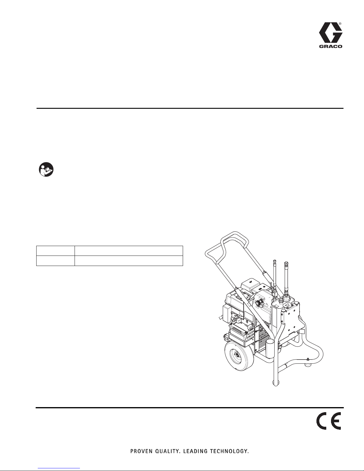
GH
Use to power XP-h™ Hydraulic Plural-Component Sprayers. For professional use only.
Not approved for use in explosive atmospheres or hazardous locations.
Important Safety Instructions
Read all warnings and instructions in this
manual and in related manuals. Save these
instructions.
Power Pack
334914A
Part No. 24X011
Maximum Working Pressure 1800 psi (12.4 MPa, 124 bar)
Related Manuals
Manual No. Description
3A0420
™
and XP-h Proportioners
XP
EN
WLD
Page 2

Contents
Warnings . . . . . . . . . . . . . . . . . . . . . . . . . . . . . . . . . 3
Component Identification . . . . . . . . . . . . . . . . . . . . 6
Lift Instructions . . . . . . . . . . . . . . . . . . . . . . . . . . . . 7
Removing Handle . . . . . . . . . . . . . . . . . . . . . . . . . . 8
Fixed Mounting (optional) . . . . . . . . . . . . . . . . . . 8
Repositioning Handle . . . . . . . . . . . . . . . . . . . . . 8
Securing Unit to Vehicle Bed . . . . . . . . . . . . . . . . . 9
Pressure Relief Procedure . . . . . . . . . . . . . . . . . . 10
Grounding . . . . . . . . . . . . . . . . . . . . . . . . . . . . . . . 10
Setup . . . . . . . . . . . . . . . . . . . . . . . . . . . . . . . . . . . . 11
Startup . . . . . . . . . . . . . . . . . . . . . . . . . . . . . . . . . . 12
Spraying . . . . . . . . . . . . . . . . . . . . . . . . . . . . . . . . . 13
Maintenance . . . . . . . . . . . . . . . . . . . . . . . . . . . . . . 14
Troubleshooting . . . . . . . . . . . . . . . . . . . . . . . . . . 15
Compensator Seal Replacement . . . . . . . . . . . . . 16
Removal . . . . . . . . . . . . . . . . . . . . . . . . . . . . . . 16
Hydraulic Pump Replacement . . . . . . . . . . . . . . . 17
Changing Hydraulic Oil . . . . . . . . . . . . . . . . . . . 17
Removal . . . . . . . . . . . . . . . . . . . . . . . . . . . . . . 17
Installation . . . . . . . . . . . . . . . . . . . . . . . . . . . . . 19
Belt Removal and Installation . . . . . . . . . . . . . . . 21
Replacing Oil Reservoir . . . . . . . . . . . . . . . . . . . . 22
Removal . . . . . . . . . . . . . . . . . . . . . . . . . . . . . . 22
Installation . . . . . . . . . . . . . . . . . . . . . . . . . . . . . 23
Changing Hydraulic Oil Filter . . . . . . . . . . . . . . . . 25
Removal . . . . . . . . . . . . . . . . . . . . . . . . . . . . . . 25
Installation . . . . . . . . . . . . . . . . . . . . . . . . . . . . . 25
Cooler Replacement . . . . . . . . . . . . . . . . . . . . . . . 26
Removal . . . . . . . . . . . . . . . . . . . . . . . . . . . . . . 26
Installation . . . . . . . . . . . . . . . . . . . . . . . . . . . . . 27
Engine Replacement . . . . . . . . . . . . . . . . . . . . . . . 28
Removal . . . . . . . . . . . . . . . . . . . . . . . . . . . . . . 28
Installation . . . . . . . . . . . . . . . . . . . . . . . . . . . . . 28
Engine Replacement . . . . . . . . . . . . . . . . . . . . . 29
Battery Replacement . . . . . . . . . . . . . . . . . . . . . . . 30
Removal . . . . . . . . . . . . . . . . . . . . . . . . . . . . . . 30
Installation . . . . . . . . . . . . . . . . . . . . . . . . . . . . . 30
Frame . . . . . . . . . . . . . . . . . . . . . . . . . . . . . . . . . . . 32
Frame Parts List . . . . . . . . . . . . . . . . . . . . . . . . 33
Frame (continued) . . . . . . . . . . . . . . . . . . . . . . . . . 34
Frame (Continued) Parts List . . . . . . . . . . . . . . 35
Hydraulic Pump and Reservoir . . . . . . . . . . . . . . . 36
Hydraulic Pump and Reservoir Parts List . . . . . 37
Battery . . . . . . . . . . . . . . . . . . . . . . . . . . . . . . . . . . . 38
Parts List . . . . . . . . . . . . . . . . . . . . . . . . . . . . . . 38
Technical Data . . . . . . . . . . . . . . . . . . . . . . . . . . . . 39
Graco Standard Warranty . . . . . . . . . . . . . . . . . . . 40
2 334194A
Page 3
Warnings
Warnings
The following warnings are for the setup, use, grounding, maintenance, and repair of this equipment. The exclamation point symbol alerts you to a general warning and the hazard symbols refer to procedure-specific risks. When
these symbols appear in the body of this manual or on warning labels, refer back to these Warnings. Product-specific
hazard symbols and warnings not covered in this section may appear throughout the body of this manual where
applicable.
WARNING
WARNINGWARNINGWARNING
FIRE AND EXPLOSION HAZARD
Flammable fumes, such as solvent and paint fumes, in work area can ignite or explode. To help prevent
fire and explosion:
• Use equipment only in well ventilated area.
• Do not fill fuel tank while engine is running or hot; shut off engine and let it cool. Fuel is flammable
and can ignite or explode if spilled on hot surface.
• Eliminate all ignition sources; such as pilot lights, cigarettes, portable electric lamps, and plastic drop
cloths (potential static arc).
• Keep work area free of debris, including solvent, rags and gasoline.
• Do not plug or unplug power cords, or turn power or light switches on or off when flammable fumes
are present.
• Ground all equipment in the work area. See Grounding instructions.
• Use only grounded hoses.
• Hold gun firmly to side of grounded pail when triggering into pail. Do not use pail liners unless they
are antistatic or conductive.
• Stop operation immediately if static sparking occurs or you feel a shock. Do not use equipment
until you identify and correct the problem.
• Keep a working fire extinguisher in the work area.
SKIN INJECTION HAZARD
High-pressure fluid from gun, hose leaks, or ruptured components will pierce skin. This may look like just
a cut, but it is a serious injury that can result in amputation. Get immediate surgical treatment.
• Do not spray without tip guard and trigger guard installed.
• Engage trigger lock when not spraying.
• Do not point gun at anyone or at any part of the body.
• Do not put your hand over the spray tip.
• Do not stop or deflect leaks with your hand, body, glove, or rag.
•Follow the Pressure Relief Procedure when you stop spraying and before cleaning, checking, or
servicing equipment.
• Tighten all fluid connections before operating the equipment.
• Check hoses and couplings daily. Replace worn or damaged parts immediately.
MOVING PARTS HAZARD
Moving parts can pinch, cut or amputate fingers and other body parts.
• Keep clear of moving parts.
• Do not operate equipment with protective guards or covers removed.
• Pressurized equipment can start without warning. Before checking, moving, or servicing equipment,
follow the Pressure Relief Procedure and disconnect all power sources.
334194A 3
Page 4
Warnings
WARNING
WARNINGWARNINGWARNING
ENTANGLEMENT HAZARD
Rotating parts can cause serious injury.
• Keep clear of moving parts.
• Do not operate equipment with protective guards or covers removed.
• Do not wear loose clothing, jewelry or long hair while operating equipment.
• Equipment can start without warning. Before checking, moving, or servicing equipment, follow the
Pressure Relief Procedure and disconnect all power sources.
CARBON MONOXIDE HAZARD
Exhaust contains poisonous carbon monoxide, which is colorless and odorless. Breathing carbon monoxide can cause death.
• Do not operate in an enclosed area.
TOXIC FLUID OR FUMES HAZARD
Toxic fluids or fumes can cause serious injury or death if splashed in the eyes or on skin, inhaled, or
swallowed.
• Read MSDSs to know the specific hazards of the fluids you are using.
• Store hazardous fluid in approved containers, and dispose of it according to applicable guidelines.
BATTERY SAFETY
The battery may leak, explode, cause burns, or cause an explosion if mishandled.
• Only use the battery type specified for use with the equipment.
• Battery maintenance must only be performed or supervised by personnel knowledgeable of
batteries and the required precautions. Keep unauthorized personnel away from battery.
• Do not dispose of battery in fire. The battery is capable of exploding.
• Follow local ordinances and/or regulations for disposal.
• Do not open or mutilate the battery. Released electrolyte has been known to be harmful to the skin
and eyes and to be toxic.
• Remove watches, rings, or other metal objects.
• Only use tools with insulated handles. Do not lay tools or metal parts on top of battery.
BURN HAZARD
Equipment surfaces and fluids that are heated can become very hot during operation. To avoid severe
burns:
• Do not touch hot fluid or equipment.
4 334194A
Page 5
Warnings
WARNING
WARNINGWARNINGWARNING
EQUIPMENT MISUSE HAZARD
Misuse can cause death or serious injury.
• Do not operate the unit when fatigued or under the influence of drugs or alcohol.
• Do not exceed the maximum working pressure or temperature rating of the lowest rated system
component. See Technical Data in all equipment manuals.
• Use fluids and solvents that are compatible with equipment wetted parts. See Technical Data in all
equipment manuals. Read fluid and solvent manufacturer’s warnings. For complete information
about your material, request MSDS from distributor or retailer.
• Do not leave the work area while equipment is energized or under pressure.
• Turn off all equipment and follow the Pressure Relief Procedure when equipment is not in use.
• Check equipment daily. Repair or replace worn or damaged parts immediately with genuine manufacturer’s replacement parts only.
• Do not alter or modify equipment. Alterations or modifications may void agency approvals and create
safety hazards.
• Make sure all equipment is rated and approved for the environment in which you are using it.
• Use equipment only for its intended purpose. Call your distributor for information.
• Route hoses and cables away from traffic areas, sharp edges, moving parts, and hot surfaces.
• Do not kink or over bend hoses or use hoses to pull equipment.
• Keep children and animals away from work area.
• Comply with all applicable safety regulations.
PERSONAL PROTECTIVE EQUIPMENT
Wear appropriate protective equipment when in the work area to help prevent serious injury, including
eye injury, hearing loss, inhalation of toxic fumes, and burns. Protective equipment includes but is not
limited to:
• Protective eyewear, and hearing protection.
• Respirators, protective clothing, and gloves as recommended by the fluid and solvent manufacturer.
CALIFORNIA PROPOSITION 65
The engine exhaust from this product contains a chemical known to the State of California to cause cancer, birth defects or other reproductive harm.
334194A 5
Page 6
Component Identification
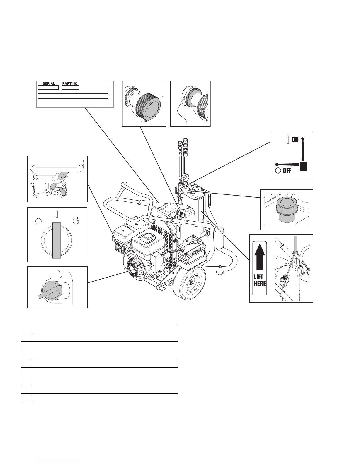
Component Identification
8
6
7
9
1
10
2
ON
OFF
START
4
3
ON
OFF
1 Engine Controls
2 Engine ON/OFF Switch (Electric-Start Units)
3 Ignition
4 Lift Location
6 Pressure Control
7 Lock Ring
8 Serial Number ID Label
9 Hydraulic Pump Valve
10 Hydraulic Oil Fill
WLE
6 334194A
Page 7
Lift Instructions
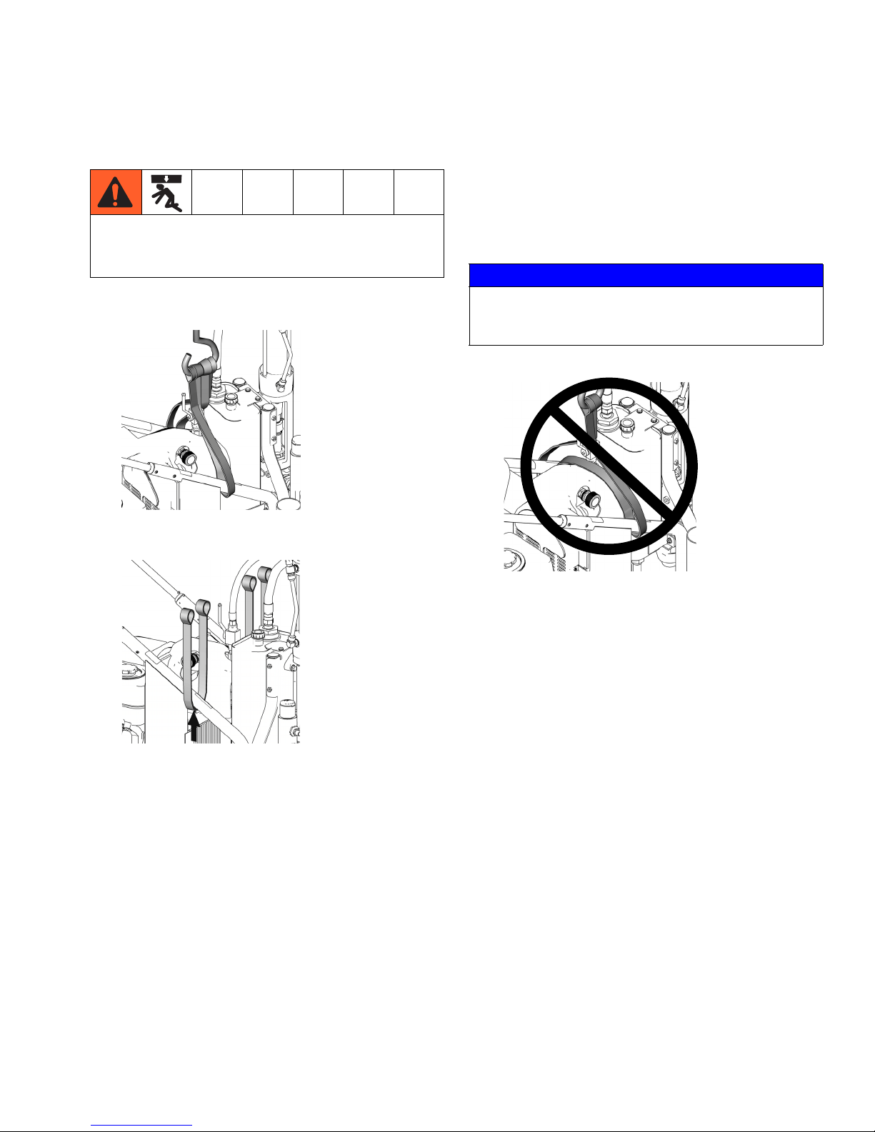
Lift Instructions
3. Be sure straps/chains used for lifting are rated to
support weight of the power pack: 390 lbs (177 kg).
To avoid injury, always use designated Lift Locations
when lifting the unit. Always use approved equipment
for securing the unit to transporting equipment.
1. When lifting the power pack, balance weight evenly
across two straps/chains as shown.
ti7840a
2. Wrap each strap/chain securely around frame
where indicated on frame label as shown.
NOTE: Lift power pack and sprayer components separately. Disconnect fluid hoses.
NOTICE
Do not lift unit with only one strap secured across
pump. This could put stress on frame and damage
pump.
ti7838a
334194A 7
ti7855a
Page 8
Removing Handle
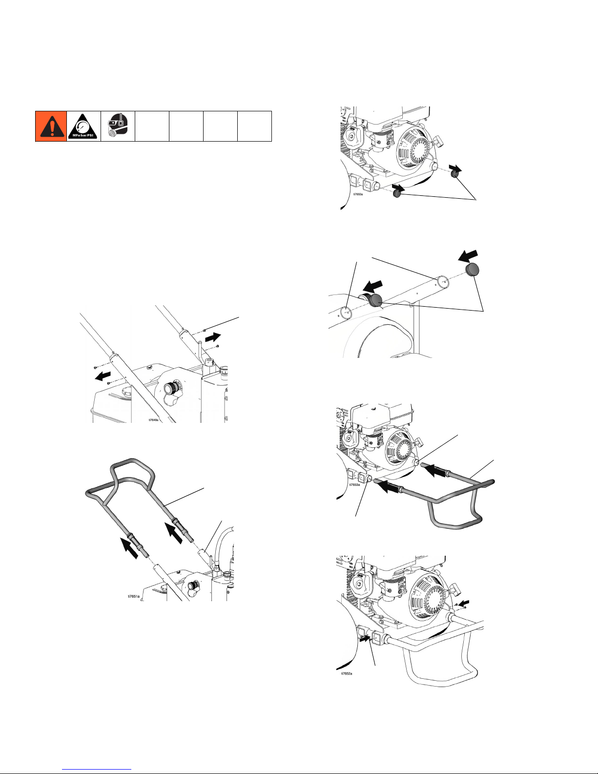
Removing Handle
Fixed Mounting (optional)
To prevent damaging the unit when transporting it in a
truck or on a trailer, Graco recommends fixed mounting
to the vehicle.
Repositioning Handle
Before you can secure the unit to a truck or trailer bed,
you must reposition the handle.
1. Remove the 4 handle sleeve screws (143).
143
3. Remove frame tube plugs (120) located behind the
wheels.
120
4. Insert plugs (120) in upper frame handle tubes (a).
(a)
120
ti7744a
2. Remove handle assembly (25) by pulling it out of
upper frame tubes (1).
25
1
5. Insert handle assembly (25) into lower frame tubes
(b). The hose bracket should face down. Adjust to
appropriate in/out location.
(b)
25
25
(b)
6. Install sleeve screws (143) in lower frame tubes.
8 334194A
143
Page 9
Securing Unit to Vehicle Bed
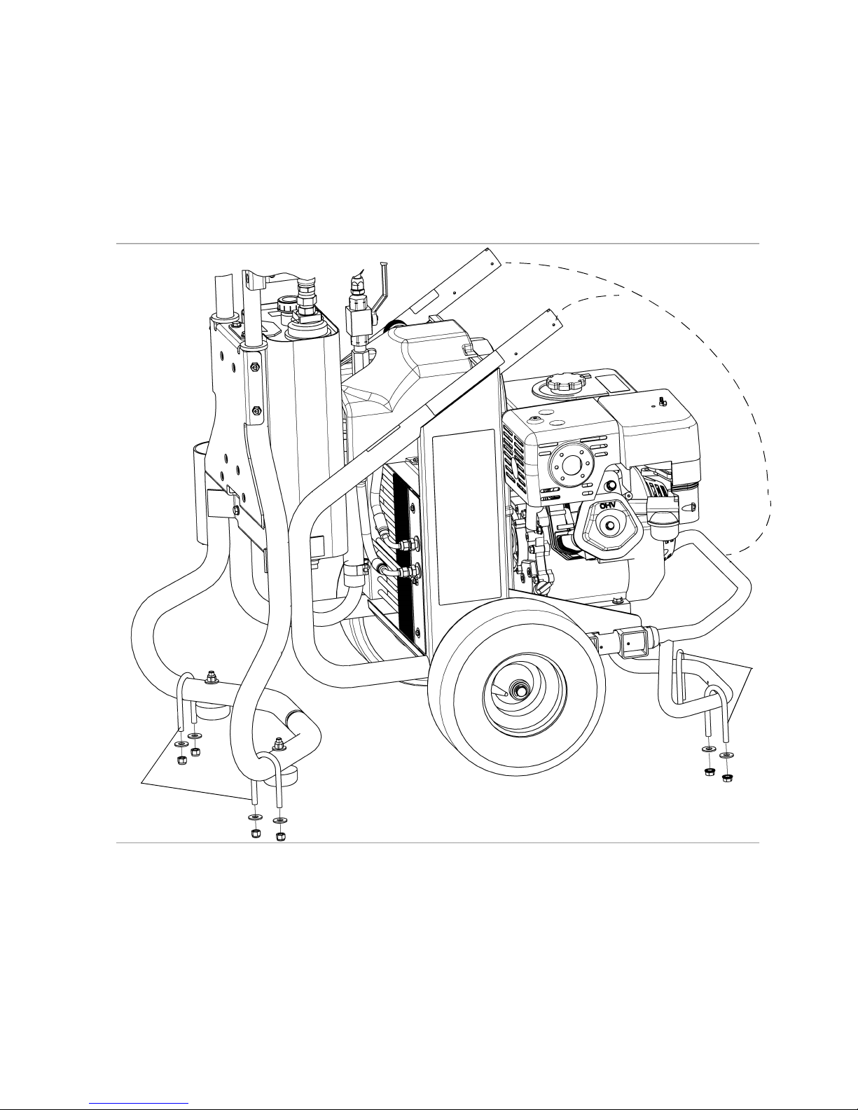
Securing Unit to Vehicle Bed
For fixed mounting, fasten U-bolts over sprayer frame
as indicated in the following illustration.
1. Reposition handle, steps 1-5, page 8.
2. Place U-bolts over sprayer frame and through holes
in vehicle bed. Place a washer and nut over bolt
end. Using a wrench, tighten nut securely.
Reposition Handle
U-bolts
U-bolts
334194A 9
ti20932a
Page 10
Pressure Relief Procedure
Pressure Relief Procedure
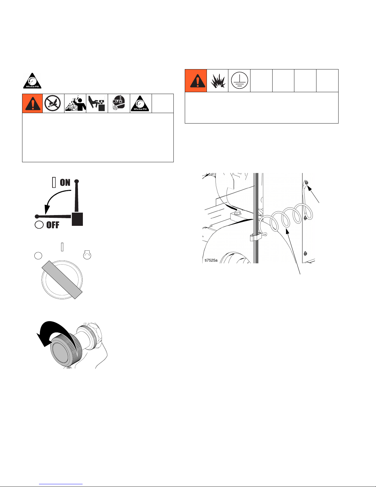
Follow the Pressure Relief Procedure whenever
you see this symbol.
This equipment stays pressurized until pressure is
manually relieved. To help prevent serious injury
from pressurized fluid, such as skin injection,
splashing fluid and moving parts, follow the Pressure
Relief Procedure when you stop spraying and before
cleaning, checking, or servicing the equipment.
1. Set pump valve OFF.
ti7108a
Grounding
The equipment must be grounded to reduce the risk of
static sparking. Static sparking can cause fumes to
ignite or explode. Grounding provides an escape wire
for the electric current.
Use ground wire and clamp (supplied). Loosen grounding lug locknut (W) and washer (X). Insert ground wire
end (Y) into lug (Z) slot and tighten locknut securely.
Connect ground clamp to a true earth ground.
W, X, Z
2. Turn engine OFF.
ON
OFF
START
ti20967a
3. Loosen Lock Ring. Turn pressure control to lowest
setting.
ti7111b
4. Trigger gun into pail to relieve pressure.
5. See XP-h manual 3A0420 for the Pressure Relief
Procedure of the XP-h proportioner.
Y
10 334194A
Page 11
Setup
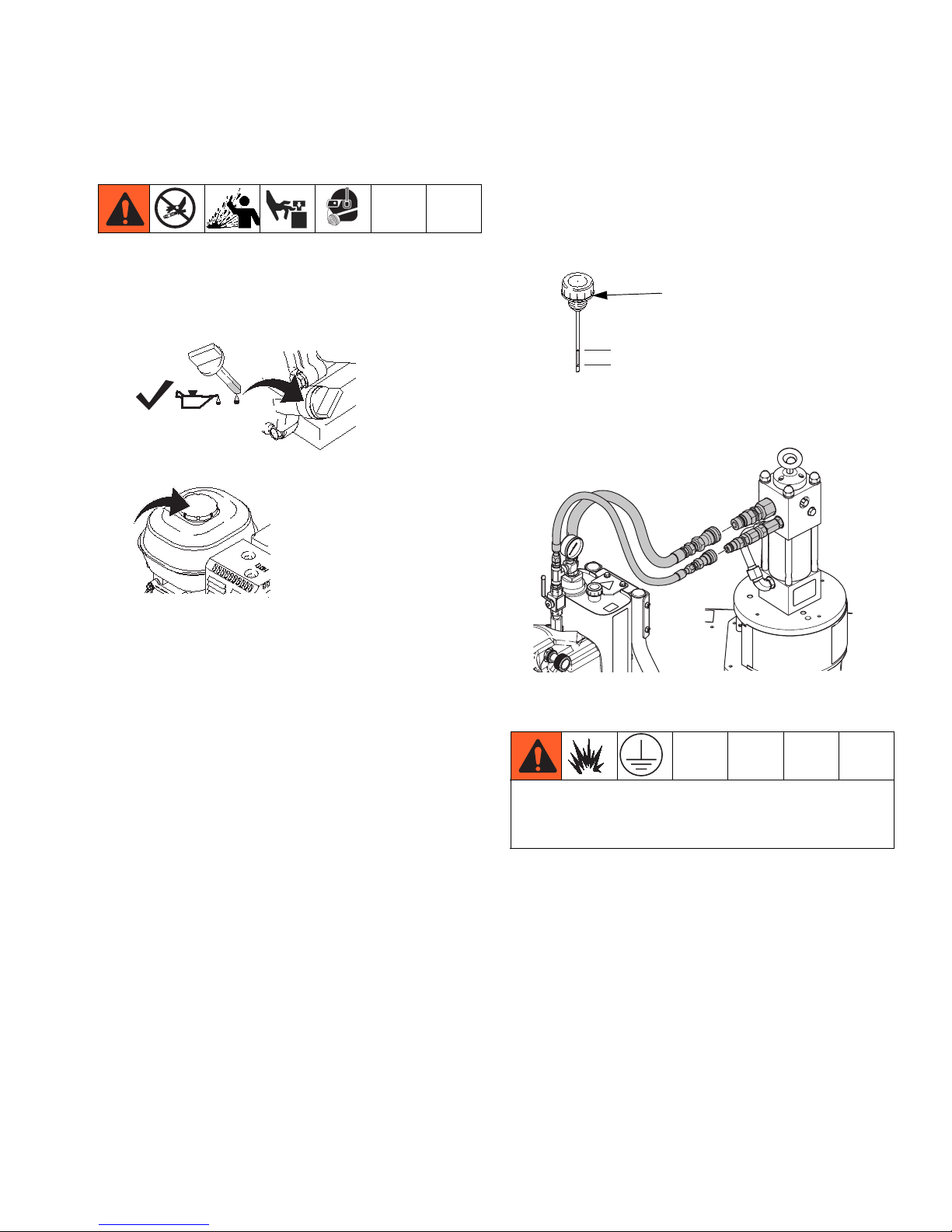
1. Follow Setup instructions in the XP-h Proportioner
manual.
2. Check engine oil level. Add SAE 10W-30 (summer)
or 5W-20 (winter), if necessary.
Setup
4. Remove the hydraulic oil fill cap (27) and check the
hydraulic reservoir oil level. Add only Graco Hydraulic Oil, ISO 46 169236 (5 gallon/18.9 liter) or 207428
(1 gallon/3.8 liter). Hydraulic reservoir capacity is
approximately 4.0 gallons (15.14 liters).
27
(cold)
3. Fill engine fuel tank.
ti5242a
ti5241a
ti5243a
Safe Range (cold)
5. Verify all hose/fitting connections from the power
pack and XP-h Proportioner are tight.
WLE
Attach XP-h Proportioner grounding clamp to earth
ground to reduce the risk of static sparking. See XP
Proportioner manual for instructions.
334194A 11
Page 12
Startup
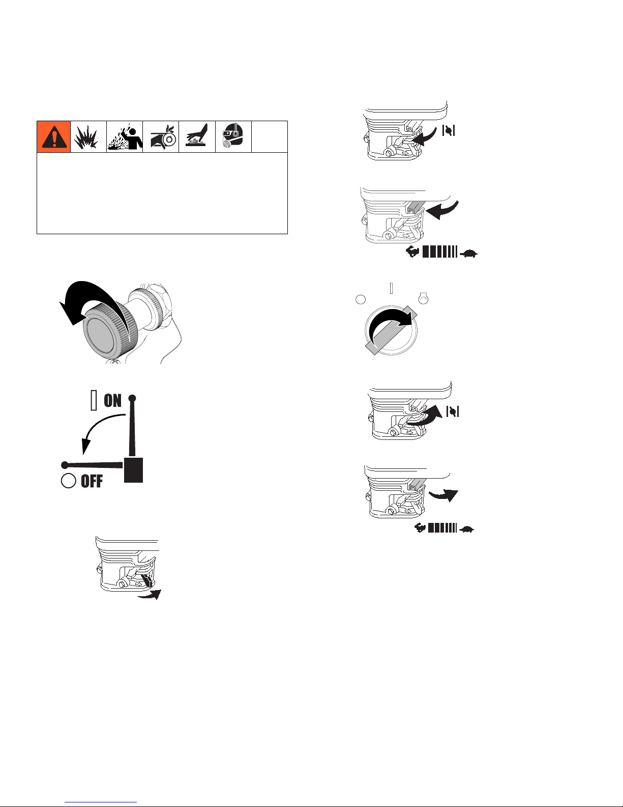
Startup
Hydraulic system and engine may become very hot
during operation and could burn skin if touched.
Flammable materials spilled on hot, bare motor could
cause fire or explosion. Have belt guard in place
during operation to reduce risk of entanglement or
loss of fingers.
1. Loosen lock nut and turn pressure control counterclockwise to lowest pressure.
ti7111b
2. Set pump valve OFF.
b. Move choke to closed.
ti5249a
c. Set throttle to fast.
ti5250a
d. Rotate key to start.
ON
OFF
START
ti20966a
e. After engine starts, move choke to open.
3. Start engine.
a. Move fuel valve to open.
ti5248a
ti5264a
f. Set throttle to desired setting.
ti7108a
ti5251a
12 334194A
Page 13

Spraying
1. Set pump valve ON.
Spraying
4. Adjust pressure to desired setting. Begin spraying.
ti7108a
2. Increase pressure enough to start hydraulic motor
stroking and allow fluid to circulate for 15 seconds;
turn pressure down.
ti7110c
3. Turn spray gun trigger safety OFF.
ti7110c
ti21062a
5. Rotate Lock Ring clockwise to set pressure.
ti20968a
334194A 13
ti21143a
Page 14

Maintenance
Maintenance
Spark Plug:
• Use BPR6ES (NGK) or W20EPR-U
(NIPPONDENSO) plug, only.
For detailed engine maintenance and specifications,
refer to separate Honda Engines Owner’s Manual,
supplied.
• Gap plug to 0.028 to 0.031 in. (0.7 to 0.8 mm).
• Use spark plug wrench when installing and
removing plug.
Frequency Procedure
Daily Check engine oil level and fill as necessary.
Daily Check hydraulic oil level and fill as necessary.
Daily Check hose for wear and damage.
Daily Check gun safety for proper operation.
Daily Check pressure drain valve for proper operation.
Daily Check and fill gas tank.
After first 20 hours
of operation
Weekly
Weekly/Daily Remove and debris or media from hydraulic rod.
After each 100
hours of operation
Semi-annually Check belt wear; replace if necessary.
Drain engine oil and refill with clean oil. Reference Honda Engines Owner’s Manual for
correct oil viscosity.
Remove engine air filter cover and clean element. Replace element, if necessary. If operating
in an unusually dusty environment; check filter daily and replace, if necessary.
Replacement elements can be purchased from your local Honda dealer.
Change engine oil. Reference Honda Engines Owner’s Manual for correct oil viscosity.
Yearly or 2000
hours
14 334194A
Replace hydraulic oil and filter element with Graco ISO 46 Hydraulic Oil 169236;
5 gallon/20 liter or 207428; 1 gallon/3.8 liter) and filter element 287871.
Page 15

Troubleshooting
Troubleshooting
PROBLEM CAUSE SOLUTION
Gas engine pulls hard (will not start). Hydraulic pressure is too high. Turn hydraulic pressure knob coun-
terclockwise to lowest setting.
Gas engine does not start. Switch OFF, low oil, no gasoline or
dead battery.
Gas engine doesn't work properly. Faulty engine. Consult engine manual, supplied.
Gas engine operates, but displacement pump doesn't operate.
Excessive leakage around hydraulic
motor piston rod wiper.
Fluid delivery is low. Pressure setting too low. Increase pressure.
The sprayer overheats. Paint buildup on hydraulic compo-
Excessive hydraulic pump noise. Low hydraulic fluid level. Turn sprayer OFF. Add fluid*.
*Check hydraulic fluid level often. Do not allow it to become too low. Use only Graco approved hydraulic fluid, page 25.
Pump valve is OFF. Set pump valve ON.
Pressure setting too low. Increase pressure.
Tip or tip filter (if used) is clogged. Remove tip and/or filter and clean.
Hydraulic fluid too low. Shut off sprayer. Add fluid*.
Belt worn, broken or off. Replace belt.
Hydraulic pump worn or damaged. Bring sprayer to Graco distributor for
Hydraulic motor not shifting. Set pump valve OFF. Turn pressure
Piston rod seal worn or damaged. Replace these parts.
Displacement pump outlet filter (if
used) is dirty or clogged.
Intake line to pump inlet is not tight. Tighten.
Hydraulic motor is worn or damaged. Bring sprayer to Graco distributor for
Large pressure drop in fluid hose. Use larger diameter or shorter hose.
nents.
Oil level is low. Fill with oil.
Consult engine manual, supplied.
Change battery if necessary.
repair.
down. Turn engine OFF. Pry rod up
or down until hydraulic motor shifts.
Clean filter.
repair.
Clean hydraulic components.
334194A 15
Page 16

Compensator Seal Replacement
Compensator Seal
Replacement
Removal
4. Install new gaskets and torque screws.
Torque 50 in-lb
4 plcs
Allow hydraulic system to cool before beginning the
service procedure to prevent injury.
1. Perform Pressure Relief Procedure, page 10.
2. Remove screw (197) and pump handle cover (196).
Remove four cover bolts (79) and cover (140).
NOTE: It is not necessary to remove the hydraulic
lines before removing the cover. The cover is
designed to provide ample room for the cover to fit
over the hose.
197
79
196
140
Compensator
Assembly
3
2
Torque 50 in-lb
4 plcs
Adapter
Block
O-Ring
Gasket
ti17601a
Lubricate before installation
O-Ring
Gasket
Note Gasket Orientation
1
4
Torque sequence: 1-2-3-4-1
All cap screws must be tightened
When compensator assembled to
Gasket Adaptor Block. Do not
pre-tighten cap screws.
5. Install cover (140) with four screws (79). Torque to
25-30 in-lb (2.8 - 3.4 N
z
m). Install pump handle
cover (196) with screw (197).
197
196
3. Remove compensator screws and separate compensator and adapter block.
16 334194A
140
79
ti7805c
ti7811c
Page 17

Hydraulic Pump Replacement
Hydraulic Pump Replacement
Changing Hydraulic Oil
NOTICE
To prevent damage to the hydraulic pump,
only use hydraulic fluid.
Draining Oil
a. Place drain pan under oil reservoir and drain
plug.
b. Unscrew reservoir (64) drain plug and drain oil
from reservoir.
1. Perform Pressure Relief Procedure, page 10.
2. Drain oil, Changing Hydraulic Oil procedure,
page 17.
3. Remove screw (197) and pump handle cover (196).
Remove four cover bolts (79) and cover (140). (It is
not necessary to remove the hydraulic lines before
removing cover. The cover is designed to provide
ample room for the cover to fit over the hose.)
196
197
79
140
ti20935a
drain
plug
Refilling Oil
a. Replace drain plug.
b. Fill tank with Graco Hydraulic Oil, ISO 46. Res-
ervoir holds approximately 4 gallons (15.14
liters).
Removal
Allow hydraulic system to cool before beginning the
service procedure to prevent injury.
ti7805b
4. Unscrew suction line connections to hydraulic
pump. Place a container under hoses to catch any
dripping oil.
334194A 17
Page 18

Hydraulic Pump Replacement
5. Remove belt cover screws (79), washers (78) and
grommets (80) (2 each side).
80
78
79
ti7796b
6. Remove belt cover (67).
67
7. Remove belt (19), page 21.
8. Loosen set-screws (87) on front of large pulley (4).
4
ti7783b
9. Remove pulley (4) from hydraulic pump shaft.
ti7795b
4
ti7807b
10. Remove nuts (10) and screws (9) holding pump to
frame.
9
10
ti7788b
18 334194A
Page 19

Hydraulic Pump Replacement
11. Remove hydraulic pump (3).
3
ti7800b
12. Remove fittings (30, 34, 35) from pump (3) and set
aside to use on the new pump.
34
3
2. Install new pump (3) in frame.
3. Install screws (9) and nuts (10). Torque to 225 +
in-lb (25.42 N•m).
9
10
ti7778b
4. Replace large pulley (4) on hydraulic pump shaft.
4
10
35
30
ti20946a
Installation
1. Install fittings (30, 34, 35) from old pump on new
pump. Torque fitting (30) and (35) to 600 +
(67.8 N•m). Torque fitting (34) to 450 in-lb (50.8
N•m).
34
3
10 in-lb
35
ti7813b
5. Align pulley (4) on shaft. When properly positioned
approximately 1/8 inch of shaft (139) will protrude.
1/8 inch
139
ti7835a
4
ti20945a
NOTE: Fill pump casing with hydraulic oil before installing fitting (34).
334194A 19
30
Page 20

Hydraulic Pump Replacement
6. Replace set-screws (87). Tighten and torque to 60 +
2 in-lb (6.8 +
0.2 N•m).
NOTE: Tighten set-screw on shaft before tightening
set-screw on pump shaft.
7. Position belt (19) over pulleys (4, 6); Installing Belt,
page 21.
8. Replace belt cover (67) and grommets (80), washers (78) and screws (79), (2 each side). Torque
screws to 25-30 in-lb (2.8 -3.4 N•m).
67
80
9. Install suction lines. Tighten fittings. Torque fitting A
to 225 +
+
10 in-lb (50.1 + 1.1. N•m). Fitting C to 225 in-lb
10 in-lb (25.4 + 1.1 N•m). Fitting B to 450
(25.4 N•m).
B
A
C
10. Install cover (140) and with four screws (79). Torque
to 25-30 in-lb (2.8 - 3.4 N•m). Install pump handle
cover (196) with screw (197).
79
196
ti7810b
ti7812b
78
197
140
79
ti7811c
11. Fill oil tank following Refilling Oil procedure on page
17.
20 334194A
Page 21

Belt Removal and Installation
1. Perform Pressure Relief Procedure, page 10.
Removing Belt
a. Loosen engine bolts (21) to relieve tension on
belt.
Belt Removal and Installation
b. Slide belt off pulleys.
Installing Belt
a. Install belt (19) over small (6) and large (4)
pulleys.
b. Tighten engine bolts (21). Torque to 225 +
in-lb (25.4 +
c. Check belt (19) alignment on both large (4) and
small pulley (6). When properly positioned over
pulleys, belt should be centered on pulleys and
completely over all grooves.
1.1 N•m).
19
10
ti7834a
Properly Aligned
NOTE: If belt is not aligned properly, to adjust belt, slowly
pull engine recoil while at the same time pushing or pulling belt to reposition over pulley.
4
Not Aligned Properly
ti7837a
334194A 21
ti20943a
6
21
Page 22

Replacing Oil Reservoir
Replacing Oil Reservoir
Removal
1. Perform Pressure Relieve Procedure, page 10.
2. Drain oil from reservoir (64) following Draining Oil
procedure, page 17. Keep plug for use on new reservoir.
ti20935a
Drain Plug
4. Loosen and remove suction hose (153).
32
ti20934a
153
5. Remove and keep suction fitting (32) for use on new
reservoir.
6. Disconnect hydraulic lines from the hydraulic pump.
100
3. Remove fill cap (27) and filter assembly (111). Keep
for use on new reservoir.
111
27
ti20942a
WLE
101
7. Remove cooler line from reservoir (64).
ti20941a
22 334194A
Page 23

Replacing Oil Reservoir
8. Remove two top bolts (86) and two bottom nuts (84)
securing reservoir (64) to frame.
86
ti20939a
64
84
ti20940a
Installation
1. Install plug (102), return elbow (31), suction fitting
(32), inlet screen (89) and filter assembly (111) in
new reservoir (64).
111
31
102
ti7893a
27
89
32
9. Lift reservoir (64) out of frame.
64
2. Install new reservoir (64) in frame.
64
ti20936a
ti20938a
334194A 23
Page 24

Replacing Oil Reservoir
3. Replace bolts (86) and nuts (84). Tighten bolts.
Torque to 125 +
10 in-lb (14 + 1.1 N•m).
4. Connect coolant line to reservoir (64). Torque to 225
in-lb (14.1 N•m).
ti20941a
5. Reattach fluid lines (100, 101). Ensure fittings are
connected securely.
100
7. Reattach suction hose (153). Toque to 600 +
in-lb (68 +
ti20934a
1.1 N•m).
153
10
8. Verify drain plug has been replaced. Fill oil reservoir
with oil to high mark on dip stick (approximately 3.5
gallons).
ti20935a
Drain Plug
6. Install filter (107).
107
9. Replace cap (27).
27
WLE
101
ti20933a
ti21063a
24 334194A
Page 25

Changing Hydraulic Oil Filter
Changing Hydraulic Oil Filter
Removal
1. Perform Pressure Relieve Procedure, page 10.
2. Loosen and remove hose (101) from fitting (103).
3. Remove filter housing (111) from reservoir (64).
4. Remove bottom filer cap (155) from housing (111).
5. Pull filter (108) off cap (155).
103
Installation
1. Install new o-ring (113) from kit.
2. Install new filter (108) over cap (155).
3. Install cap (155) and filter (108) in filter housing
(111). Hand tighten cap till snug. Then torque to 375
+
10 in-lb (42 + 1.1 N•m).
4. Install filter housing (111) into reservoir.
5. Install fitting (103) in filter housing (111). Torque to
600 +
10 in-lb (67.8 + 1.1 N•m).
6. Reattach hose (101) to fitting (103). Torque to 450 +
10 in-lb (51 +
1.1 N•m).
101
111
108
113
155
ti7763a
334194A 25
Page 26

Cooler Replacement
Cooler Replacement
Removal
1. Perform Pressure Relieve Procedure, page 10.
2. Loosen ground screw and remove ground clamp
(95) from sprayer.
4. Remove screws (79), washers (78) and support bar
(77) from cooling coil (72).
72
77
79
78
ti7794b
95
3. Loosen and remove return line to oil tank and
hydraulic line to cooler.
5. Remove coil (72) from sprayer frame.
72
ti7799b
ti7792b
ti7802b
26 334194A
Page 27

Cooler Replacement
Installation
1. Install new coil (72). Replace support bar (77),
washers (78) and screws (79). Tighten screws.
72
ti7768b
2. Replace bar and screws. Torque to 25-30 in-lb
(2.8-3.4 N•m).
3. Reconnect return line to oil tank and hydraulic line
to cooler. Torque to 225 in-lb (25.4 N•m).
ti7802b
4. Replace ground wire (95) and tighten screw. Torque
to 25-30 in-lb (2.8 - 3.4 N•m).
95
77
ti7799b
79
78
334194A 27
ti7794b
Page 28

Engine Replacement
Engine Replacement
Removal
1. Perform Pressure Relieve Procedure, page 10.
2. Remove screws (79) and washers (78) and belt
cover (67). See F
3. Remove belt (19), page 21.
4. Remove screws (21), washers (70) and nuts (10)
securing motor (5) to frame.
5. Disconnect battery cables and voltage regulator.
IG
. 1, page 29.
Removing Pulley
NOTE: This procedure is only necessary if you are
replacing the motor. When you install a new motor
you reuse the existing pulley.
Removal
a. Loosen set screw (87) located on the side of the
pulley (6).
b. Remove large bolt (24) in the center of pulley
(6).
c. Pull pulley (6) off motor (5).
Installation
a. Position new pulley (6) on motor (5).
b. Install large bolt (24) and washer (65) in center
of pulley (6). Torque to 125 +
(14.1 +
1.1 N•m).
10 in-lb
6. Remove motor (5) from frame.
Replacing Motor Fan
Removal
a. Loosen and remove bolts (86) on front of fan
(14).
b. Pull fan (14) off small pulley (6).
Installation
a. Position new fan (14) over small pulley (6).
b. Replace bolts (86) and tighten securely.Torque
to 125 +
10 in-lb (14.1 + 1.1 N•m).
ti20931a
c. Tighten set screw (87). Torque to 60 +
(25.4 N•m).
2 in-lb
Installation
1. Install motor (5) in frame.
2. Reconnect battery cables and voltage regulator
connection.
ti20931a
3. Replace all screws (21), washers (70) and nuts (10).
Tighten securely.
4. Install belt (19) over pulleys (4, 6), page 21.
5. Replace belt cover (67) and screws (79) and washers (78) (2 each side). Using a wrench tighten bolts.
Torque to 25-30 in-lb (2.8-3.4 N•m).
28 334194A
Page 29

Engine Replacement
5
87
65
67
14
86
78
79
10
Engine Replacement
19
4
ti20932a
FIG. 1
24
6
45
46
21
334194A 29
Page 30

Battery Replacement
Battery Replacement
Removal
1. Loosen wing nuts (48) and remove washers (58,
49), battery clamp (47), and hooks (38). Set parts
aside.
2. Remove terminal covers (43, 44) and cables (45,
46) from battery lugs (33).
3. Dispose of battery per local codes and regulations.
45
48
49
58
47
38
Installation
1. Place new battery (33) on pad (39).
2. Reconnect battery cables (45, 46) and terminal covers (43, 44) to battery.
3. Install battery clamp (47).
44
46
43
33
39
86
37
ti20817a
30 334194A
Page 31

Battery Replacement
334194A 31
Page 32

Frame
Frame
1
25
116
145
144
92
78
95
7979
146
72
143143
177
172
77
78
79
154
WLD
137
32
153
86
120
84
86
71
7070
68
69
32 334194A
Page 33

Frame Parts List
Frame
Ref. Part Description Qty.
1 15G839 FRAME, GH833, painted 1
25 287797 HANDLE, weldment, GH833 1
32 120068 FITTING, hydraulic 1
68 801504 FOOT, rubber 2
69 100454 SCREW, cap hex hd 2
70 100132 WASHER, flat 4
71 101566 NUT, lock 2
72 287925 COOLER, oil 1
77 15H480 BAR, support 1
78 120339 WASHER, fender 8
79 C20474 SCREW, self-tapping 10
84 110996 NUT, hex, flange head 2
86 110963 SCREW, cap, flange head 12
92 15G797 SLEEVE, handle 2
Ref. Part Description Qty.
95 237686 WIRE, ground assembly w/ clamp 1
116 238049 FLUID, TSL, 4 oz 1
120 120314 PLUG, tube 4
137 15G813 HOSE, coupled 1
143 109032 SCREW, mach, pnh 4
144 112827 BUTTON, snap 2
145 108068 PIN, spring straight 2
146 116891 WASHER 2
153 15G541 TUBE, J suction 1
154 101818 CLAMP, hose 1
172 15G906 LABEL, lift here 2
177 16D577 LABEL, USA made with Honda 1
334194A 33
Page 34

Frame (continued)
Frame (continued)
34 334194A
ti7685c
Page 35

Frame (Continued) Parts List
Frame (continued)
Qty
Ref. Part Description
2 119509 WHEEL, pneumatic 2
5 16U399 ENGINE, gas, 13HP, electric start,
18amp
5a VOLTAGE REGULATOR
(see Honda manual)
10 112958 NUT, hex, flanged 6
20 15G547 SPACER, axle 2
21 116780 SCREW, hex, hd, flanged 4
22 154628 WASHER 2
23 120211 RING, retaining, e-ring 2
45 113951 CABLE, electric, neg 1
46 107073 CABLE, electric, positive 1
49 110755 WASHER 2
67 288099 KIT, repair, cover, fan pulley 1
78 120339 WASHER, fender 8
79 C20474 SCREW, self-tapping 10
80 120415 GROMMET, pulley fan GH833 4
81 100021 SCREW, cap hex hd 2
82 102040 WASHER, lock 2
86 110963 SCREW, cap, flange head 12
100 17D581 HOSE, coupled 1
101 17D582 HOSE, coupled 1
Ref. Part Description
.
112 120304 FITTING, nipple 1
120 120314 PLUG, tube 4
1
140 288098 KIT, repair, pump cover
1
140a COVER, pump handle 1
140b SCREW, thread form, hi/lo 1
140c COVER, pump 1
140d SCREW, self-tapping 4
168 16U558 LABEL, brand, big rig, rear 1
173 15G907 LABEL, Honda GX390 13HP 1
▲178 15D523 LABEL, warning, EN/FR/ES 1
▲179 194126 LABEL, warning 1
▲180 189285 LABEL, caution 2
▲183 198492 LABEL, warning 1
222 120444 SCREW 2
223 101345 NUT 2
246 17E120 FITTING, q.d., 1/2 in. 1
247 127133 FITTING, nipple 1
248 17E122 FITTING, q.d., 3/4 in. 1
▲Replacement Danger and Warning labels, tags, and
cards are available at no cost.
(includes 140a, 140b, 140c, 140d)
Qty
.
1
334194A 35
Page 36

Hydraulic Pump and Reservoir
Hydraulic Pump and Reservoir
36 334194A
Page 37

Hydraulic Pump and Reservoir Parts List
Hydraulic Pump and Reservoir
Qty
Ref. Part Description
3 24X189 PUMP, hydraulic
(includes 9, 10, 13, 134, 135, 136)
4 15G812 PULLEY, pump 1
6 15G811 PULLEY, drive, engine 1
9 111193 SCREW, cap flange hd 2
10 112958 NUT, hex, flanged 6
13 15B438 KNOB, pressure 1
14 119971 FAN 1
19 120172 BELT, poly-v 1
24 116596 SCREW, cap, hex head 1
27 116915 CAP, oil fill 1
30 120066 FITTING, elbow, hydraulic 1
31 120064 FITTING, elbow, hydraulic 1
32 120068 FITTING, hydraulic 1
34 116793 FITTING 1
35 120067 FITTING 1
64 15G545 RESERVOIR, painted 1
65 100731 WASHER 1
84 110996 NUT, hex, flange head 2
86 110963 SCREW, cap, flange head 12
87 100002 SCREW, set, sch 3
89 120137 FILTER, suction 1
98 15G784 HOSE, coupled 1
99 15G782 HOSE, coupled 1
102 124489 PLUG, pipe 1
103 120063 FITTING, hydraulic 1
107 120140 VALVE, ball, assembly 1
108 120310 FILTER, hydraulic fluid 1
111 15H246 HOUSING, filter, hydraulic 1
Ref. Part Description
.
112 120304 FITTING, nipple, straight 1
1
113 120315 O-RING, packing 1
134 117560 SCREW, set, socket head 1
135 15A464 LABEL, control 1
136 15G767 COLLAR, locking, pressure knob 1
139 801137 KEY, engine, pulley 1
152 120175 FITTING, ball valve 1
155 15H247 CAP, filter, hydraulic 1
172 15G906 LABEL, lift here 2
174 15G908 LABEL, hydraulic lever on/off 1
▲178 15D523 LABEL, warning, EN/FR/ES 1
▲180 189285 LABEL, caution 1
▲181 16P142 LABEL, hydraulic fluid only 1
205 183401 KEY, pump, pulley 1
220 287100 KIT, repair (includes 220a-220d) 1
220a O-RING, oval
220b GASKET, comp/block
220c O-RING
220d GASKET, block/cover
242 158491 NIPPLE 1
243 103475 FITTING, tee 1
244 100206 ADAPTER 1
245 102814 GAUGE, pressure 1
246 112307 ELBOW, street 1
Kit 287871 includes 108, 113
▲Replacement Danger and Warning labels, tags, and
cards are available at no cost.
Qty
.
334194A 37
Page 38

Battery
Battery
48
58
47
38
45
44
46
49
43
33
39
37
350
185
ti20817a
86
Parts List
Qty
Ref. Part Description
33 115753 BATTERY, 33 AH, sealed 1
37 16U412 TRAY, battery, gh-es, painted 1
38 107068 HOOK, bolt 2
39 801972 PAD, battery 1
43 801958 PROTECTOR, terminal, red 1
44 801959 TERMINAL, protector, black 1
45 113951 CABLE, electric, neg (black) 1
46 107073 CABLE, electric, positive (red) 1
Ref. Part Description
.
47 107069 CLAMP, battery 1
48 100011 NUT, wing 2
49 110755 WASHER, plain 2
58 100016 WASHER, lock 2
86 110963 SCREW, cap, flange head 12
185 16U559 LABEL, brand, es, side 1
350 15F366 PAD, foam 1
Qty
.
38 334194A
Page 39

Technical Data
GH™ Power Pack
US Metric
Hydraulic Pressure 1800 psi 12.4 MPa, 124 bar
Hydraulic Reservoir Capacity 4.0 gallons 15.1 liters
Honda Motor 13 HP 9.7 KW
Hydraulic Supply 1/2 in JIC
Return Line 3/4 in JIC
Dimensions
Weight 390 lb 177 kg
Height 49 in. 124 cm
Width 28 in. 71 cm
Length 43 in. 109 cm
Sounds Levels
(measured at maximum normal load conditions)
Sound Pressure (measured per ISO-9614-2) 91 dB(A)
Sound Power 106 dB(A)
Miscellaneous
Graco-Approved Hydraulic Oil
169236 5 gallons 19 liters
207428 1 gallon 3.8 liters
Technical Data
334194A 39
Page 40

Graco Standard Warranty
Graco warrants all equipment referenced in this document which is manufactured by Graco and bearing its name to be free from defects in
material and workmanship on the date of sale to the original purchaser for use. With the exception of any special, extended, or limited warranty
published by Graco, Graco will, for a period of twelve months from the date of sale, repair or replace any part of the equipment determined by
Graco to be defective. This warranty applies only when the equipment is installed, operated and maintained in accordance with Graco’s written
recommendations.
This warranty does not cover, and Graco shall not be liable for general wear and tear, or any malfunction, damage or wear caused by faulty
installation, misapplication, abrasion, corrosion, inadequate or improper maintenance, negligence, accident, tampering, or substitution of
non-Graco component parts. Nor shall Graco be liable for malfunction, damage or wear caused by the incompatibility of Graco equipment with
structures, accessories, equipment or materials not supplied by Graco, or the improper design, manufacture, installation, operation or
maintenance of structures, accessories, equipment or materials not supplied by Graco.
This warranty is conditioned upon the prepaid return of the equipment claimed to be defective to an authorized Graco distributor for verification of
the claimed defect. If the claimed defect is verified, Graco will repair or replace free of charge any defective parts. The equipment will be returned
to the original purchaser transportation prepaid. If inspection of the equipment does not disclose any defect in material or workmanship, repairs
will be made at a reasonable charge, which charges may include the costs of parts, labor, and transportation.
THIS WARRANTY IS EXCLUSIVE, AND IS IN LIEU OF ANY OTHER WARRANTIES, EXPRESS OR IMPLIED, INCLUDING BUT NOT
LIMITED TO WARRANTY OF MERCHANTABILITY OR WARRANTY OF FITNESS FOR A PARTICULAR PURPOSE.
Graco’s sole obligation and buyer’s sole remedy for any breach of warranty shall be as set forth above. The buyer agrees that no other remedy
(including, but not limited to, incidental or consequential damages for lost profits, lost sales, injury to person or property, or any other incidental or
consequential loss) shall be available. Any action for breach of warranty must be brought within two (2) years of the date of sale.
GRACO MAKES NO WARRANTY, AND DISCLAIMS ALL IMPLIED WARRANTIES OF MERCHANTABILITY AND FITNESS FOR A
PARTICULAR PURPOSE, IN CONNECTION WITH ACCESSORIES, EQUIPMENT, MATERIALS OR COMPONENTS SOLD BUT NOT
MANUFACTURED BY GRACO. These items sold, but not manufactured by Graco (such as electric motors, switches, hose, etc.), are subject to
the warranty, if any, of their manufacturer. Graco will provide purchaser with reasonable assistance in making any claim for breach of these
warranties.
In no event will Graco be liable for indirect, incidental, special or consequential damages resulting from Graco supplying equipment hereunder, or
the furnishing, performance, or use of any products or other goods sold hereto, whether due to a breach of contract, breach of warranty, the
negligence of Graco, or otherwise.
FOR GRACO CANADA CUSTOMERS
The Parties acknowledge that they have required that the present document, as well as all documents, notices and legal proceedings entered into,
given or instituted pursuant hereto or relating directly or indirectly hereto, be drawn up in English. Les parties reconnaissen
rédaction du présente document sera en Anglais, ainsi que tous documents, avis et procédures judiciaires exécutés, donnés ou intentés, à la suite
de ou en rapport, directement ou indirectement, avec les procédures concernées.
t avoir convenu que la
Graco Information
For the latest information about Graco products, visit www.graco.com.
For patent information, see www.graco.com/patents.
TO PLACE AN ORDER, contact your Graco distributor or call 1-800-690-2894 to identify the nearest distributor.
All written and visual data contained in this document reflects the latest product information available at the time of publication.
Graco reserves the right to make changes at any time without notice.
For patent information, see www.graco.com/patents.
Original instructions.
International Offices: Belgium, China, Japan, Korea
GRACO INC. AND SUBSIDIARIES • P.O. BOX 1441 • MINNEAPOLIS MN 55440-1441 • USA
Copyright 2015, Graco Inc. All Graco manufacturing locations are registered to ISO 9001.
This manual contains English. MM 334914
Graco Headquarters: Minneapolis
www.graco.com
Revision A, April 2015
 Loading...