

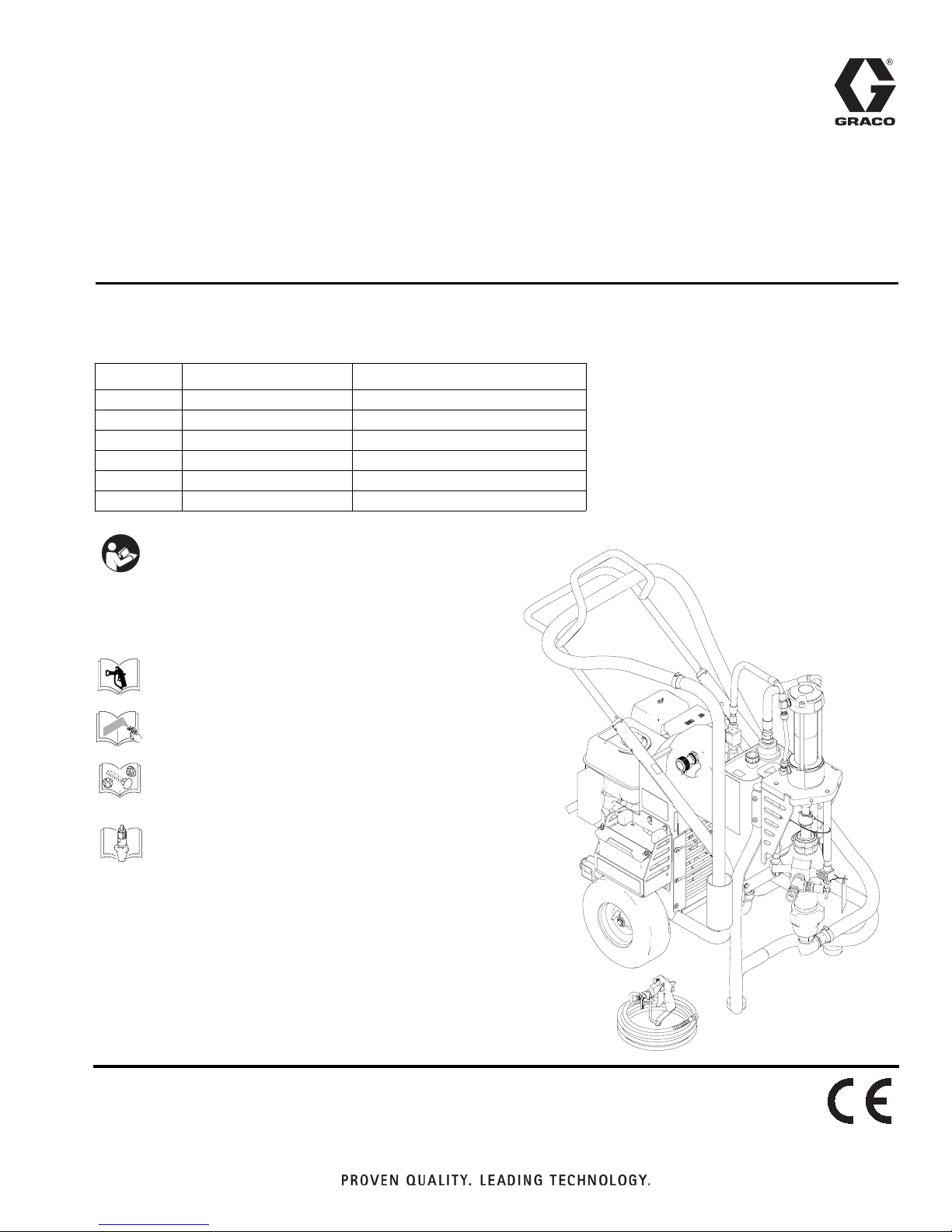
Graco GH 16U277, GH 16U279, GH 16U280, GH 16U278, GH 16U285 Repair Manual
...
Repair
™
GH
- Use with Architectural Coatings, Paints, Roof Coatings and Below Grade Coatings -
Model Description Maximum Working Pressure
16U277 GH1017es Bare 1000 psi (6.9 MPa, 69 bar)
16U278 GH2570es Bare 2500 psi (17.2 MPa, 172 bar)
16U279 GH733es Bare 4000 psi (27.6 MPa, 276 bar)
16U280 GH5040es Bare 5000 psi (34.5 MPa, 345 bar)
16U285 GH933es Bare 7250 psi (50.0 MPa, 500 bar)
16U281 GH933 Bare 7250 psi (50.0 MPa, 500 bar)
Important Safety Instructions
Read all warnings and instructions in this
manual. Save these instructions.
Related Manuals:
Series Big Rig Sprayers
311254
312145
332157A
EN
332156
332158
308043
311825
311762
ti20726a

Contents
Warnings . . . . . . . . . . . . . . . . . . . . . . . . . . . . . . . . . 3
Component Identification . . . . . . . . . . . . . . . . . . . . 5
Pressure Relief Procedure . . . . . . . . . . . . . . . . . . . 6
General Repair Information . . . . . . . . . . . . . . . . . . 6
Grounding . . . . . . . . . . . . . . . . . . . . . . . . . . . . . . 6
Maintenance . . . . . . . . . . . . . . . . . . . . . . . . . . . . . . . 7
Troubleshooting . . . . . . . . . . . . . . . . . . . . . . . . . . . . 8
Compensator Seal Replacement . . . . . . . . . . . . . 10
Removal . . . . . . . . . . . . . . . . . . . . . . . . . . . . . . 10
Displacement Pump Replacement . . . . . . . . . . . . 11
Removal . . . . . . . . . . . . . . . . . . . . . . . . . . . . . . 11
Installation . . . . . . . . . . . . . . . . . . . . . . . . . . . . . 12
Displacement Pump Replacement
(2570 Pump Only) . . . . . . . . . . . . . . . . . . . . . . 13
Removal . . . . . . . . . . . . . . . . . . . . . . . . . . . . . . 13
Installation . . . . . . . . . . . . . . . . . . . . . . . . . . . . . 14
Displacement Pump Service . . . . . . . . . . . . . . . . 15
Disconnect Displacement Pump . . . . . . . . . . . . 15
Reconnect Displacement Pump . . . . . . . . . . . . 15
Pump Power Head Replacement . . . . . . . . . . . . . 16
Removal . . . . . . . . . . . . . . . . . . . . . . . . . . . . . . 16
Installation . . . . . . . . . . . . . . . . . . . . . . . . . . . . . 16
Hydraulic Motor . . . . . . . . . . . . . . . . . . . . . . . . . . . 17
Hydraulic Pump Replacement . . . . . . . . . . . . . . . 18
Changing Hydraulic Oil . . . . . . . . . . . . . . . . . . . 18
Removal . . . . . . . . . . . . . . . . . . . . . . . . . . . . . . 18
Installation . . . . . . . . . . . . . . . . . . . . . . . . . . . . . 20
Belt Removal and Replacement
(recommended method) . . . . . . . . . . . . . . . . . 22
Removing Belt . . . . . . . . . . . . . . . . . . . . . . . . . . 22
Installing Belt . . . . . . . . . . . . . . . . . . . . . . . . . . . 22
Alternate Belt Removal and Installation . . . . . . . 23
Replacing Oil Reservoir . . . . . . . . . . . . . . . . . . . . 24
Removal . . . . . . . . . . . . . . . . . . . . . . . . . . . . . . 24
Installation . . . . . . . . . . . . . . . . . . . . . . . . . . . . . 25
Changing Hydraulic Fluid Filter . . . . . . . . . . . . . . 27
Removal . . . . . . . . . . . . . . . . . . . . . . . . . . . . . . 27
Installation . . . . . . . . . . . . . . . . . . . . . . . . . . . . . 27
Cooler Replacement . . . . . . . . . . . . . . . . . . . . . . . 28
Removal . . . . . . . . . . . . . . . . . . . . . . . . . . . . . . 28
Installation . . . . . . . . . . . . . . . . . . . . . . . . . . . . . 29
Engine Replacement . . . . . . . . . . . . . . . . . . . . . . . 30
Removal . . . . . . . . . . . . . . . . . . . . . . . . . . . . . . 30
Installation . . . . . . . . . . . . . . . . . . . . . . . . . . . . . 30
Engine Replacement . . . . . . . . . . . . . . . . . . . . . 31
Removing Handle . . . . . . . . . . . . . . . . . . . . . . . . . . 32
Fixed Mounting (optional) . . . . . . . . . . . . . . . . . 32
Repositioning Handle . . . . . . . . . . . . . . . . . . . . 32
Securing Unit to Vehicle Bed . . . . . . . . . . . . . . . . 33
Notes . . . . . . . . . . . . . . . . . . . . . . . . . . . . . . . . . . . . 34
Notes . . . . . . . . . . . . . . . . . . . . . . . . . . . . . . . . . . . . 35
Graco Standard Warranty . . . . . . . . . . . . . . . . . . . 36
2 332157A
Warnings
Warnings
The following warnings are for the setup, use, grounding, maintenance, and repair of this equipment. The exclamation point symbol alerts you to a general warning and the hazard symbols refer to procedure-specific risks. When
these symbols appear in the body of this manual or on warning labels, refer back to these Warnings. Product-specific
hazard symbols and warnings not covered in this section may appear throughout the body of this manual where
applicable.
WARNING
WARNINGWARNINGWARNING
FIRE AND EXPLOSION HAZARD
Flammable fumes, such as solvent and paint fumes, in work area can ignite or explode. To help prevent
fire and explosion:
• Use equipment only in well ventilated area.
• Eliminate all ignition sources; such as pilot lights, cigarettes, portable electric lamps, and plastic drop
cloths (potential static arc).
• Keep work area free of debris, including solvent, rags and gasoline.
• Do not plug or unplug power cords, or turn power or light switches on or off when flammable fumes
are present.
• Ground all equipment in the work area. See Grounding instructions.
• Use only grounded hoses.
• Hold gun firmly to side of grounded pail when triggering into pail. Do not use pail liners unless they
are antistatic or conductive.
• Stop operation immediately if static sparking occurs or you feel a shock. Do not use equipment
until you identify and correct the problem.
• Keep a working fire extinguisher in the work area.
SKIN INJECTION HAZARD
High-pressure spray is able to inject toxins into the body and cause serious bodily injury. In the event
that injection occurs, get immediate surgical treatment.
• Do not aim the gun at, or spray any person or animal.
• Keep hands and other body parts away from the discharge. For example, do not try to stop leaks
with any part of the body.
• Always use the nozzle tip guard. Do not spray without nozzle tip guard in place.
• Use Graco nozzle tips.
• Use caution when cleaning and changing nozzle tips. In the case where the nozzle tip clogs while
spraying, follow the Pressure Relief Procedure for turning off the unit and relieving the pressure
before removing the nozzle tip to clean.
• Do not leave the unit energized or under pressure while unattended. When the unit is not in use, turn
off the unit and follow the Pressure Relief Procedure for turning off the unit.
• Check hoses and parts for signs of damage. Replace any damaged hoses or parts.
• This system is capable of producing 7250 psi (50.0 MPa, 500 bar). Use Graco replacement parts or
accessories that are rated a minimum of 7250 psi (50.0 MPa, 500 bar).
• Always engage the trigger lock when not spraying. Verify the trigger lock is functioning properly.
• Verify that all connections are secure before operating the unit.
• Know how to stop the unit and bleed pressure quickly. Be thoroughly familiar with the controls.
332157A 3
Warnings
WARNING
WARNINGWARNINGWARNING
MOVING PARTS HAZARD
Moving parts can pinch, cut or amputate fingers and other body parts.
• Keep clear of moving parts.
• Do not operate equipment with protective guards or covers removed.
• Pressurized equipment can start without warning. Before checking, moving, or servicing equipment,
follow the Pressure Relief Procedure and disconnect all power sources.
SUCTION HAZARD
Powerful suction could cause serious injury.
• Never place hands near the pump fluid inlet when pump is operating or pressurized.
CARBON MONOXIDE HAZARD
Exhaust contains poisonous carbon monoxide, which is colorless and odorless. Breathing carbon
monoxide can cause death.
• Do not operate in an enclosed area.
TOXIC FLUID OR FUMES HAZARD
Toxic fluids or fumes can cause serious injury or death if splashed in the eyes or on skin, inhaled, or
swallowed.
• Read MSDSs to know the specific hazards of the fluids you are using.
• Store hazardous fluid in approved containers, and dispose of it according to applicable guidelines.
BATTERY SAFETY
The battery may leak, explode, cause burns, or cause an explosion if mishandled.
•
Only use the battery type specified for use with the equipment. See Technical Data.
•
Battery maintenance must only be performed or supervised by personnel knowledgeable of batteries and
the required precautions. Keep unauthorized personnel away from battery.
•
Do not dispose of battery in fire. The battery is capable of exploding.
•
Follow local ordinances and/or regulations for disposal.
•
Do not open or mutilate the battery. Released electrolyte has been known to be harmful to the skin and
eyes and to be toxic.
•
Remove watches, rings, or other metal objects.
•
Only use tools with insulated handles. Do not lay tools or metal parts on top of battery.
BURN HAZARD
Equipment surfaces and fluids that are heated can become very hot during operation. To avoid severe
burns:
• Do not touch hot fluid or equipment.
PERSONAL PROTECTIVE EQUIPMENT
Wear appropriate protective equipment when in the work area to help prevent serious injury, including
eye injury, hearing loss, inhalation of toxic fumes, and burns. This protective equipment includes but is
not limited to:
• Protective eyewear, and hearing protection.
• Respirators, protective clothing, and gloves as recommended by the fluid and solvent manufacturer.
4 332157A

Component Identification
Component Identification
6
7
8
1
9
ON
OFF
START
2
3
ON
OF
10
11
4
5
1 Engine Controls
2 Engine ON/OFF Switch (Electric-Start Units)
3 Engine ON/OFF Switch (Pull-Start Units)
4 Lift Location
5 Suction Tube Holder
6 Pressure Control
7 Lock Ring
8 Serial Number ID Label
9 Hydraulic Pump Valve
10 Hydraulic Oil Fill
11 Pressure Bleed Valve, T handle
12 Trigger Lock
ti20727a
12
332157A 5
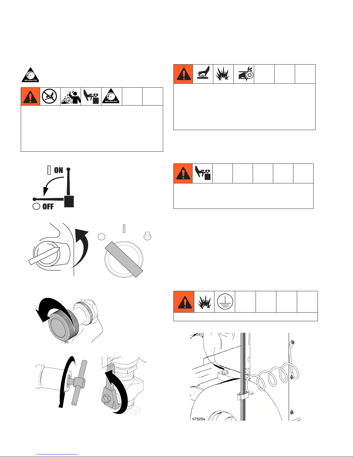
Pressure Relief Procedure
Pressure Relief Procedure
Follow the Pressure Relief Procedure whenever
you see this symbol.
This equipment stays pressurized until pressure is
manually relieved. To help prevent serious injury
from pressurized fluid, such as skin injection,
splashing fluid and moving parts, follow the Pressure
Relief Procedure when you stop spraying and before
cleaning, checking, or servicing the equipment.
1. Set pump valve OFF.
2. Turn engine OFF.
ON
OFF
ON
OFF
or
START
General Repair Information
Hydraulic system and engine may become very hot
during operation and could burn skin if touched.
Flammable materials spilled on hot, bare motor
could cause fire or explosion. Have belt guard in
place during operation to reduce risk of pinching or
loss of fingers.
• Install belt guard before operation of sprayer and
replace if damaged. Belt guard reduces risk of
pinching and loss of fingers.
To reduce risk of serious injury, do not touch
moving parts with fingers or tools while testing the
repair.
• Keep all screws, nuts, washers, etc. removed during
repair procedures. These parts usually are not provided with replacement kits.
• Test repairs after problems are corrected.
• If sprayer does not operate properly, review repair
procedure to verify you did it correctly.
See Troubleshooting, page 8.
ti5261a
3. Turn pressure to lowest setting. Trigger gun into pail
ti20967a
Grounding
to relieve pressure.
Ground sprayer with grounding clamp to earth ground.
ti7111b
4. Open prime valve (vertical).
ti7120b
6 332157A
ti21061a
Maintenance
Maintenance
Spark Plug:
• Use BPR6ES (NGK) or W20EPR-U
(NIPPONDENSO) plug, only.
For detailed engine maintenance and specifications,
refer to separate Honda Engines Owner’s Manual,
supplied.
• Gap plug to 0.028 to 0.031 in. (0.7 to 0.8 mm).
• Use spark plug wrench when installing and
removing plug.
Frequency Procedure
Daily Check engine oil level and fill as necessary.
Daily Check hydraulic oil level and fill as necessary.
Daily Check hose for wear and damage.
Daily Check gun safety for proper operation.
Daily Check pressure drain valve for proper operation.
Daily Check and fill gas tank.
Daily Check that displacement pump is tight.
Check level of TSL in displacement pump packing nut. Fill nut, if necessary. Keep TSL in
Daily
After first 20 hours
of operation
Weekly
Weekly/Daily Remove and debris or media from hydraulic rod.
nut to help prevent fluid build up on piston rod and premature wear of packings and pump
corrosion.
Drain engine oil and refill with clean oil. Reference Honda Engines Owner’s Manual for
correct oil viscosity.
Remove engine air filter cover and clean element. Replace element, if necessary. If operating
in an unusually dusty environment; check filter daily and replace, if necessary.
Replacement elements can be purchased from your local Honda dealer.
After each 100
hours of operation
Semi-annually Check belt wear; replace if necessary.
Yearly or 2000
hours
332157A 7
Change engine oil. Reference Honda Engines Owner’s Manual for correct oil viscosity.
Replace hydraulic oil and filter element with Graco ISO 46 Hydraulic Oil 169236;
5 gallon/20 liter or 207428; 1 gallon/3.8 liter) and filter element 287871.

Troubleshooting
Troubleshooting
PROBLEM CAUSE SOLUTION
Gas engine pulls hard (will not start). Hydraulic pressure is too high. Turn hydraulic pressure knob coun-
terclockwise to lowest setting.
Gas engine does not start. Switch OFF, low oil, no gasoline or
dead battery.
Gas engine doesn't work properly. Faulty engine. Consult engine manual, supplied.
Gas engine operates, but displacement pump doesn't operate.
Displacement pump operates, but
output is low on upstroke.
Displacement pump operates but
output is low on downstroke and/or
on both strokes.
Paint leaks and runs over side of wetcup.
Excessive leakage around hydraulic
motor piston rod wiper.
Fluid delivery is low. Pressure setting too low. Increase pressure.
Pump valve is OFF. Set pump valve ON.
Pressure setting too low. Increase pressure.
Displacement pump outlet filter (if
used) is dirty or clogged.
Tip or tip filter (if used) is clogged. Remove tip and/or filter and clean.
Hydraulic fluid too low. Shut off sprayer. Add fluid*.
Belt worn, broken or off. Replace belt.
Hydraulic pump worn or damaged. Bring sprayer to Graco distributor for
Dried paint seized paint pump rod. Service pump. See manuals 308043,
Hydraulic motor not shifting. Set pump valve OFF. Turn pressure
Piston ball check not seating properly.
Piston packings worn or damaged. Replace packings. See manuals
Piston packings worn or damaged. Tighten packing nut or replace pack-
Intake valve ball check not seating
properly.
Suction tube air leak.
Loose wet-cup. Tighten wet-cup enough to stop leak-
Throat packings worn or damaged. Replace packings. See manuals
Piston rod seal worn or damaged. Replace these parts.
Displacement pump outlet filter (if
used) is dirty or clogged.
Intake line to pump inlet is not tight. Tighten.
Hydraulic motor is worn or damaged. Bring sprayer to Graco distributor for
Large pressure drop in fluid hose. Use larger diameter or shorter hose.
Consult engine manual, supplied.
Change battery if necessary.
Clean the filter.
repair.
311825, 311762.
down. Turn engine OFF. Pry rod up
or down until hydraulic motor shifts.
Service piston ball check. See manuals 308043, 311825, 311762.
308043, 311825, 311762.
ings. See manuals 308043, 311825,
311762.
Service intake valve ball check. See
manuals 308043, 311825, 311762.
age.
308043, 311825, 311762.
Clean filter.
repair.
8 332157A
PROBLEM CAUSE SOLUTION
Troubleshooting
The sprayer overheats. Paint buildup on hydraulic compo-
Clean hydraulic components.
nents.
Oil level is low. Fill with oil.
Spitting from gun. Air in fluid pump or hose. Check for loose connections on
siphon assembly, tighten, then reprime pump.
Loose intake suction. Tighten.
Fluid supply is low or empty. Refill supply container.
Excessive hydraulic pump noise. Low hydraulic fluid level. Turn sprayer OFF. Add fluid*.
*Check hydraulic fluid level often. Do not allow it to become too low. Use only Graco approved hydraulic fluid, page 27.
332157A 9
Compensator Seal Replacement
Compensator Seal
Replacement
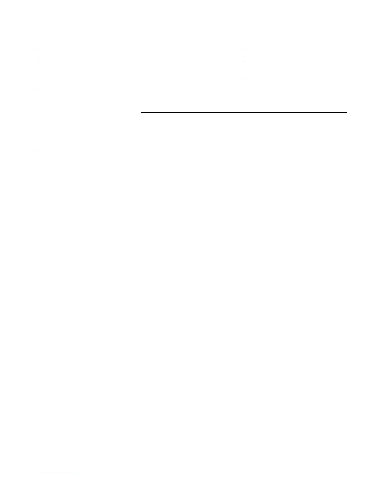
Removal
4. Install new gaskets and torque screws.
Torque 50 in-lb
4 plcs
1. Perform Pressure Relief Procedure, page 6. Allow
hydraulic system to cool before beginning the
service procedure.
2. Remove screw (197) and pump handle cover (196).
Remove four cover bolts (79) and cover (140).
NOTE: It is not necessary to remove the hydraulic
lines before removing the cover. The cover is
designed to provide ample room for the cover to fit
over the hose.
197
79
196
140
Compensator
Assembly
3
2
Torque 50 in-lb
4 plcs
Adapter
Block
O-Ring
Gasket
ti17601a
Lubricate before installation
O-Ring
Gasket
Note Gasket Orientation
1
4
Torque sequence: 1-2-3-4-1
All cap screws must be tightened
When compensator assembled to
Gasket Adaptor Block. Do not
pre-tighten cap screws.
5. Install cover (140) with four screws (79). Torque to
25-30 in-lb (2.8 - 3.4 N
z
m). Install pump handle
cover (196) with screw (197).
197
196
3. Remove compensator screws and separate compensator and adapter block.
10 332157A
140
79
ti7805c
ti7811c
Displacement Pump Replacement
Displacement Pump
Replacement
See manual 308043, 311825, or 311762 for pump repair
instructions.
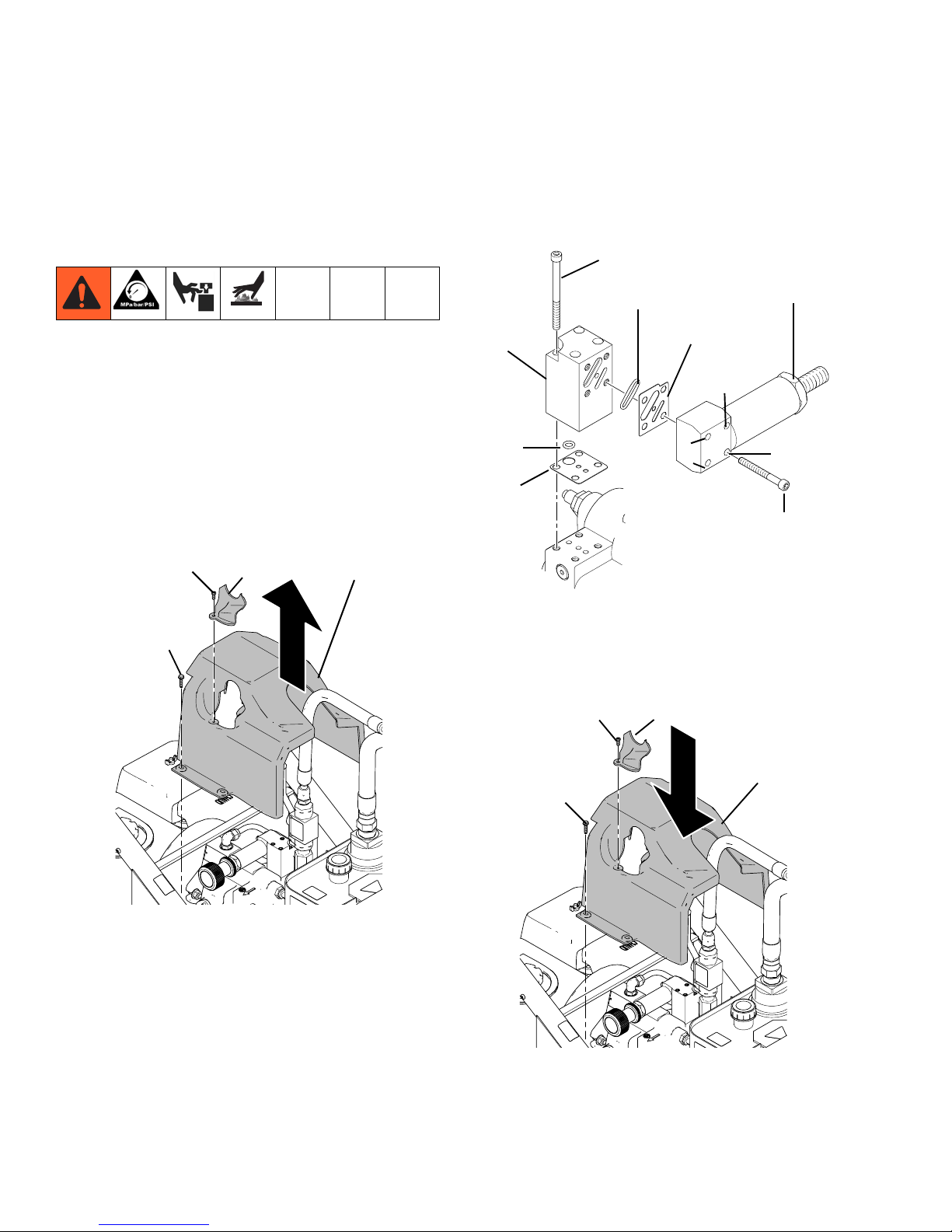
Removal
1. Flush pump (36). Stop pump on down stroke if
possible.
2. Perform Pressure Relief Procedure, page 6.
3. Remove suction set (147) from pump (36).
36
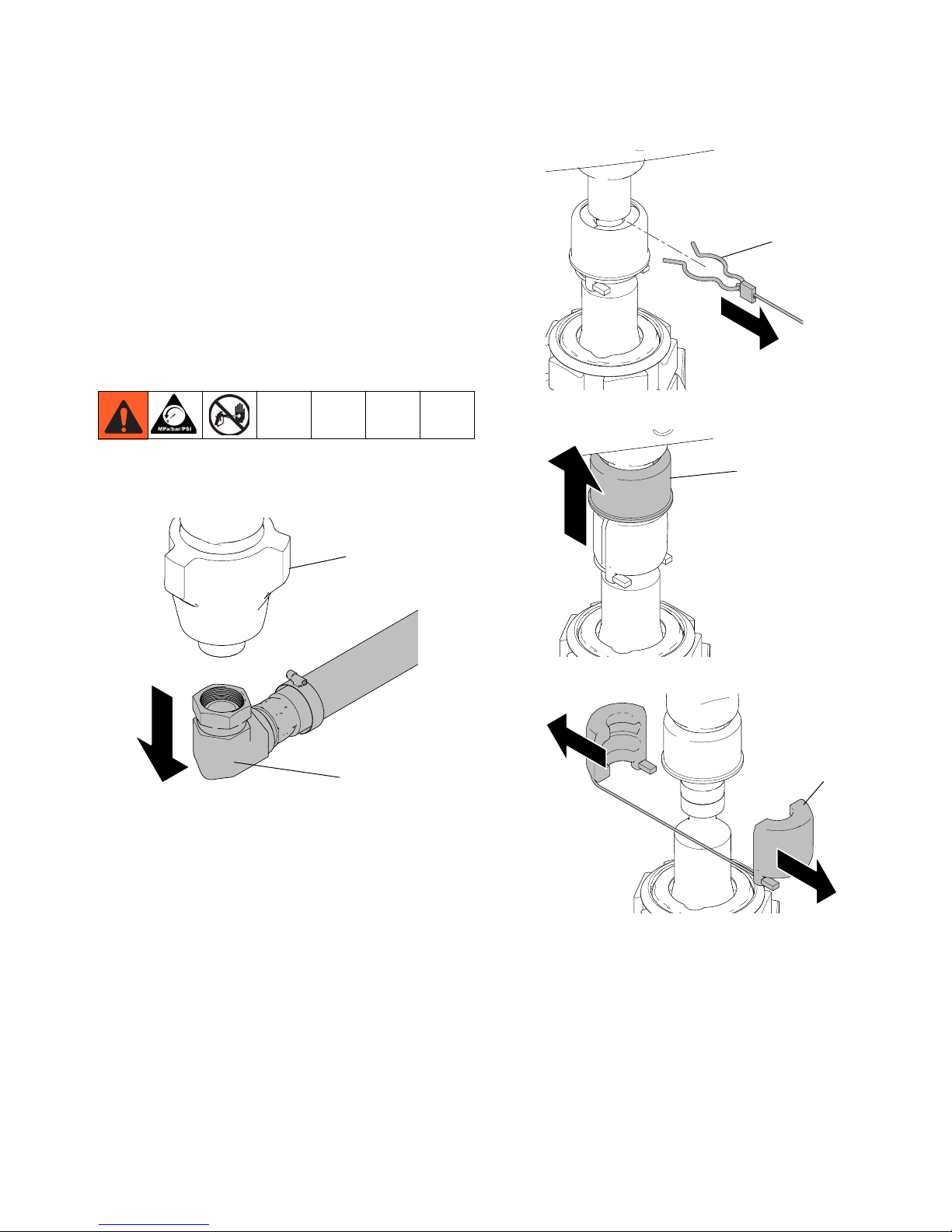
4. Remove clip (121).
121
ti20965a
5. Slide cover up (124).
124
147
ti20964a
6. Separate coupling (125) and remove.
ti20955a
125
ti20963a
332157A 11
 Loading...