

Page 1
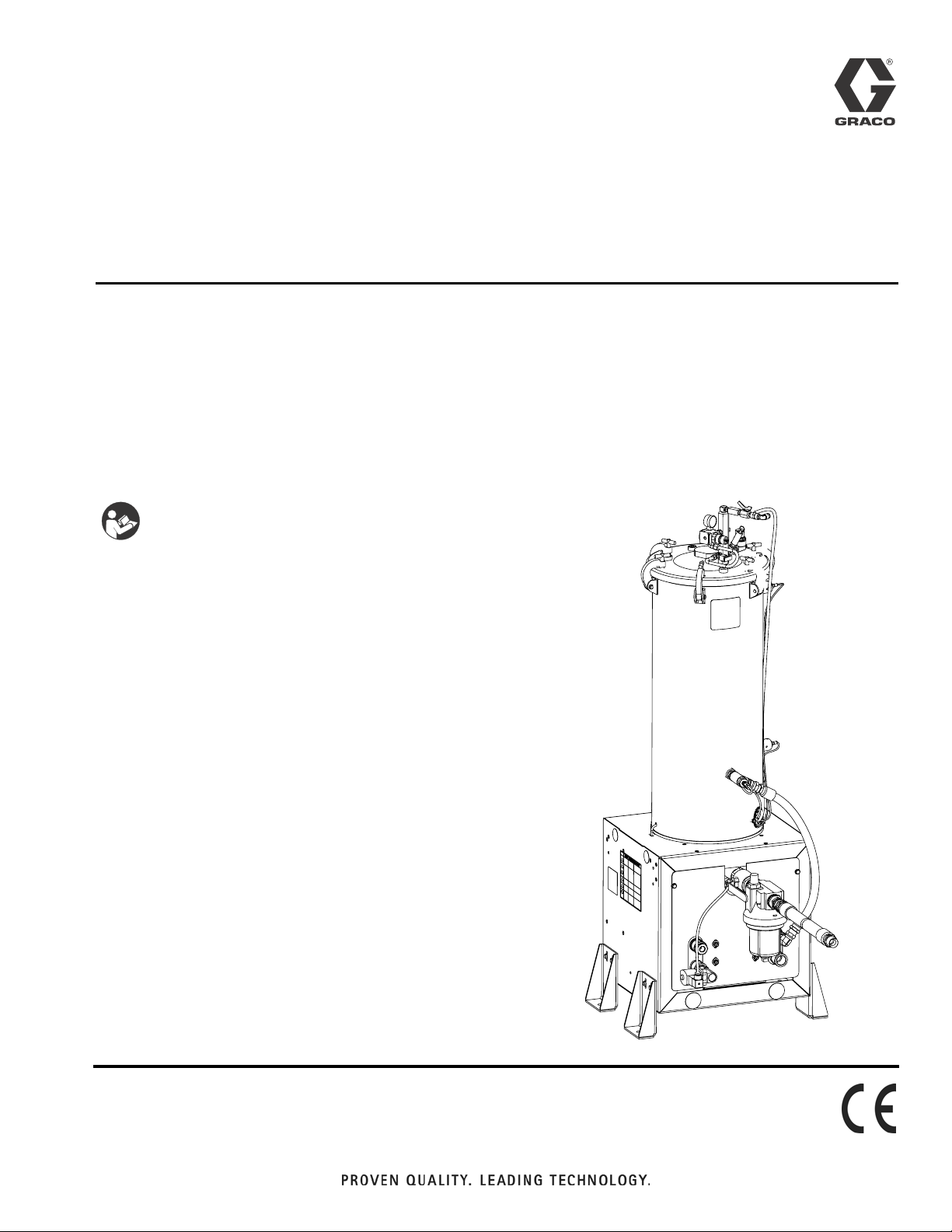
Instructions - Parts
Stainless Steel
3A0395R
Tank Stands
For supplying material to HFR™ plural-component proportioners. For professional use
only.
Not approved for use in European explosive atmosphere locations.
100 psi (0.7 MPa, 7.0 bar) Maximum Working Pressure
100 psi (0.7 MPa, 7.0 bar) Maximum Air Pressure
Important Safety Instructions
Read all warnings and instructions in this
manual. Save these instructions.
EN
See page 3 for model information.
r_24C317_3A0395a_1c
Page 2

Contents
Models . . . . . . . . . . . . . . . . . . . . . . . . . . . . . . . . . . . 3
Related Manuals . . . . . . . . . . . . . . . . . . . . . . . . . . . 3
Warnings . . . . . . . . . . . . . . . . . . . . . . . . . . . . . . . . . 4
Important Two-Component Material Information . 6
Isocyanate Conditions . . . . . . . . . . . . . . . . . . . . . 6
Material Self-ignition . . . . . . . . . . . . . . . . . . . . . . 6
Keep Components A and B Separate . . . . . . . . . 6
Moisture Sensitivity of Isocyanates . . . . . . . . . . . 6
Foam Resins with 245 fa Blowing Agents . . . . . . 6
Changing Materials . . . . . . . . . . . . . . . . . . . . . . . 7
Component Identification . . . . . . . . . . . . . . . . . . . . 8
Tank Feed System . . . . . . . . . . . . . . . . . . . . . . . 8
Electrical Panel Components . . . . . . . . . . . . . . . 9
Installation . . . . . . . . . . . . . . . . . . . . . . . . . . . . . . . 12
Grounding . . . . . . . . . . . . . . . . . . . . . . . . . . . . . 12
Install Tank Stand . . . . . . . . . . . . . . . . . . . . . . . 12
Install Barrel Style Level Sensors . . . . . . . . . . . 12
Install Ultrasonic Level Sensor . . . . . . . . . . . . . 14
Install Chiller (customer supplied) . . . . . . . . . . . 14
Auto-Refill Installation: customer supplied feed
system . . . . . . . . . . . . . . . . . . . . . . . . . . . . 15
Auto-Refill Installation: Graco supplied feed system
15
Setup . . . . . . . . . . . . . . . . . . . . . . . . . . . . . . . . . . . . 16
Calibrate Barrel Style Level Sensors . . . . . . . . . 16
Vacuum De-gas . . . . . . . . . . . . . . . . . . . . . . . . . 16
Operation . . . . . . . . . . . . . . . . . . . . . . . . . . . . . . . . 17
Startup . . . . . . . . . . . . . . . . . . . . . . . . . . . . . . . 17
Pressure Relief Procedure . . . . . . . . . . . . . . . . 17
Maintenance . . . . . . . . . . . . . . . . . . . . . . . . . . . . . . 18
Daily Maintenance . . . . . . . . . . . . . . . . . . . . . . 18
Weekly Maintenance . . . . . . . . . . . . . . . . . . . . . 18
Install Upgrade Tokens . . . . . . . . . . . . . . . . . . . 18
Troubleshooting . . . . . . . . . . . . . . . . . . . . . . . . . . . 19
Repair . . . . . . . . . . . . . . . . . . . . . . . . . . . . . . . . . . . 27
Replace Agitator Fuse . . . . . . . . . . . . . . . . . . . 27
Tank Lid Gasket . . . . . . . . . . . . . . . . . . . . . . . . 27
Level Sensor and Well . . . . . . . . . . . . . . . . . . . 29
Electrical Schematics . . . . . . . . . . . . . . . . . . . . . . 30
Electrical Panel, Tank Stand with Agitator,
Heater/Chiller . . . . . . . . . . . . . . . . . . . . . . . 30
Electrical Panel, Tank Stand with Agitator . . . . . 34
Parts . . . . . . . . . . . . . . . . . . . . . . . . . . . . . . . . . . . . 37
38L and 75L Tank Modules . . . . . . . . . . . . . . . . 37
2 Gallon Tank Module - 24J243 . . . . . . . . . . . . . 43
Heated Tank Assemblies . . . . . . . . . . . . . . . . . . 46
Tank Lid Assemblies . . . . . . . . . . . . . . . . . . . . . 47
Electrical Panel, 230V for Heat . . . . . . . . . . . . . 50
Electrical Panel, 230V for No Heat . . . . . . . . . . 51
Electrical Panel, 230V for 2 Gallon Tanks Only . 54
Heat Exchanger Assembly . . . . . . . . . . . . . . . . 56
Air Dryer Filter . . . . . . . . . . . . . . . . . . . . . . . . . . 57
Ball Valve Assemblies . . . . . . . . . . . . . . . . . . . . 58
Recirculation Probe Assembly . . . . . . . . . . . . . . 59
Transfer Pump Valve, 24C157 . . . . . . . . . . . . . . 60
Accessories and Kits . . . . . . . . . . . . . . . . . . . . . . . 61
Dimensions . . . . . . . . . . . . . . . . . . . . . . . . . . . . . . . 66
Technical Data . . . . . . . . . . . . . . . . . . . . . . . . . . . . 67
Graco Standard Warranty . . . . . . . . . . . . . . . . . . . 68
2 3A0395R
Page 3
Models
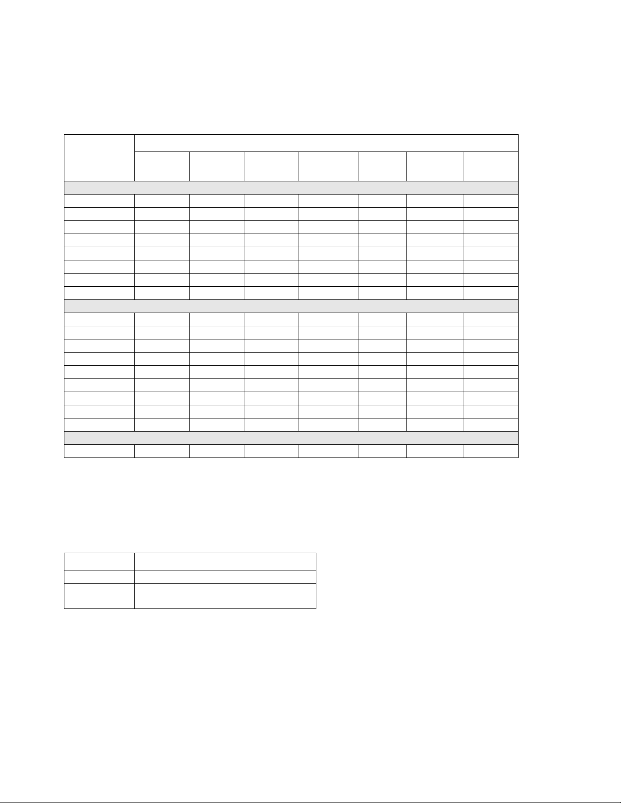
The following table lists the tank stand module part numbers and the components included with each.
Includes:
Models
Part
24D562
24D564
24D568
24D569
24D570
24D571
24D572
24D573
24D565
24C317
24D574
24D575
24D576
24D577
24D578
24D579
24P091
24J243
Slinger
Agitator
✔✔✔✔
✔✔
✔✔ ✔
✔✔✔ ✔ ✔
✔✔✔ ✔
✔✔✔✔
✔✔
✔✔ ✔
✔✔✔ ✔ ✔
✔✔✔ ✔
✔✔✔✔✔
Plate Heat Insulation Chiller
46 Liter Tanks
✔✔ ✔
75 Liter Tanks
✔✔ ✔
7.5 Liter Tanks
Desiccant
Dryer
Level
Sensors
✔
✔
✔
Related Manuals
Component manuals listed below are in English. Manuals are available at www.graco.com.
Manual No.
3A1936 Pneumatic and Electric Agitator Kits
3A1962 Pneumatic and Electric Agitators with
3A0395R 3
Description
Heat Blanket Kits
Page 4
Warnings
Warnings
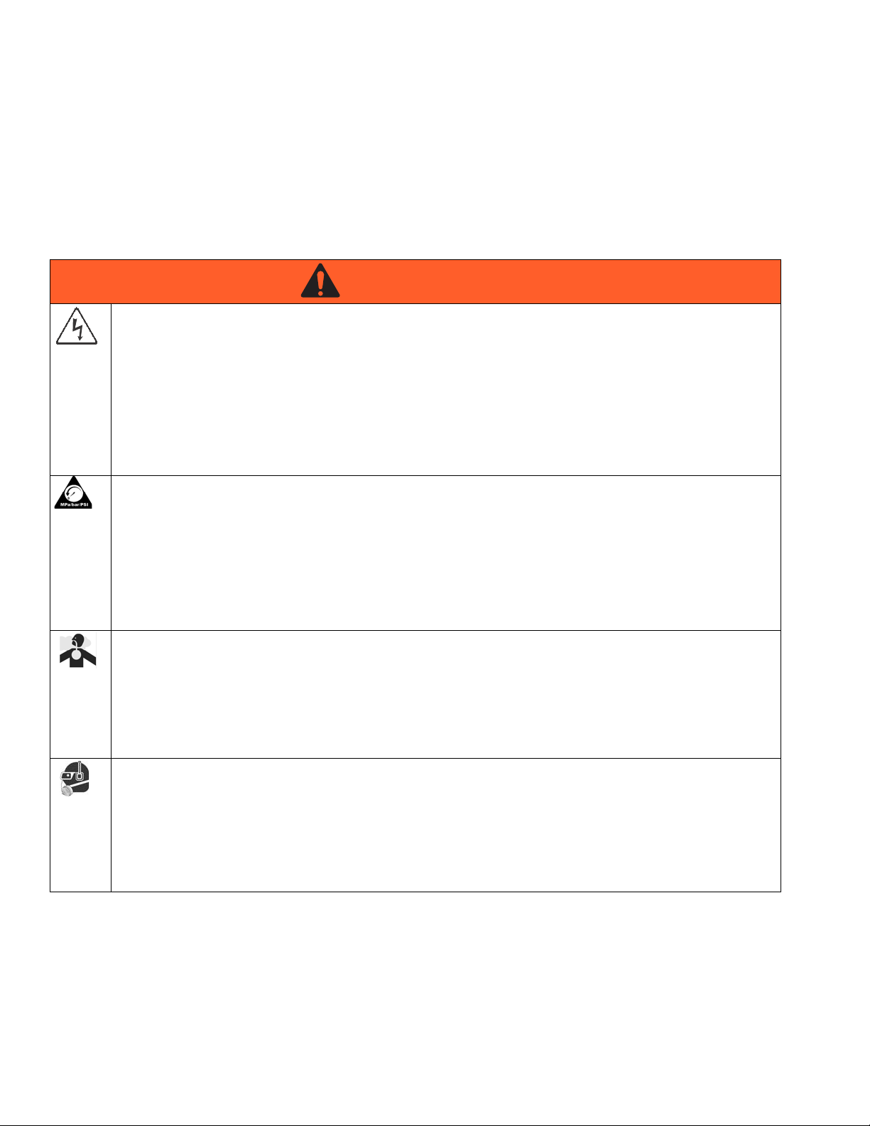
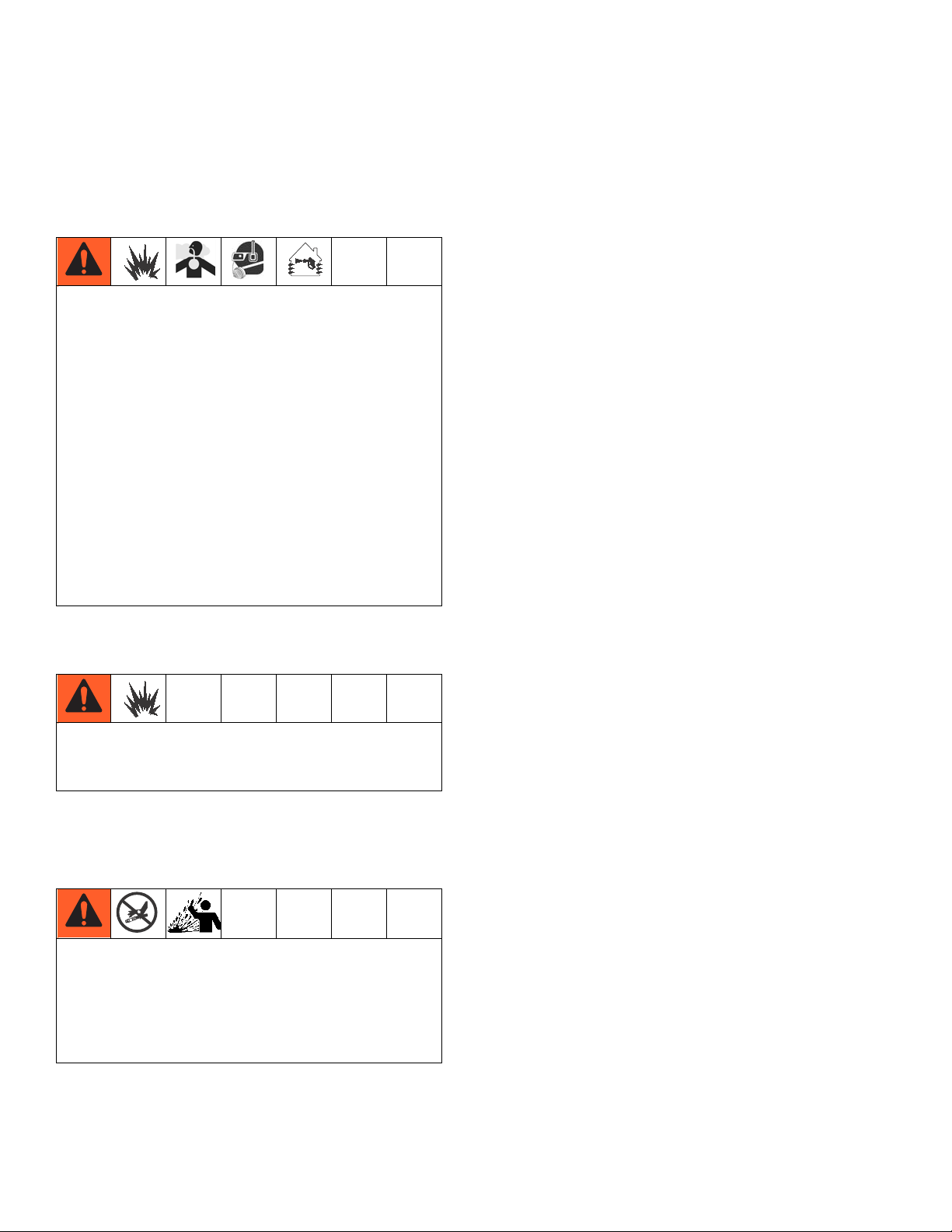
The following warnings are for the setup, use, grounding, maintenance, and repair of this equipment. The exclamation point symbol alerts you to a general warning and the hazard symbols refer to procedure-specific risks. When
these symbols appear in the body of this manual, refer back to these Warnings. Product-specific hazard symbols and
warnings not covered in this section may appear throughout the body of this manual where applicable.
WARNING
WARNINGWARNINGWARNING
ELECTRIC SHOCK HAZARD
This equipment must be grounded. Improper grounding, setup, or usage of the system can cause electric
shock.
• Turn off and disconnect power at main switch before disconnecting any cables and before servicing
equipment.
• Connect only to grounded power source.
• All electrical wiring must be done by a qualified electrician and comply with all local codes and regulations.
PRESSURIZED EQUIPMENT HAZARD
Fluid from the gun/dispense valve, leaks, or ruptured components can splash in the eyes or on skin and
cause serious injury.
•Follow the Pressure Relief Procedure when you stop spraying and before cleaning, checking, or ser-
vicing equipment.
• Tighten all fluid connections before operating the equipment.
• Check hoses, tubes, and couplings daily. Replace worn or damaged parts immediately.
TOXIC FLUID OR FUMES HAZARD
Toxic fluids or fumes can cause serious injury or death if splashed in the eyes or on skin, inhaled, or swallowed.
• Read MSDSs to know the specific hazards of the fluids you are using.
• Store hazardous fluid in approved containers, and dispose of it according to applicable guidelines.
• Always wear chemically impermeable gloves when spraying, dispensing, or cleaning equipment.
PERSONAL PROTECTIVE EQUIPMENT
You must wear appropriate protective equipment when operating, servicing, or when in the operating area
of the equipment to help protect you from serious injury, including eye injury, hearing loss, inhalation of
toxic fumes, and burns. This equipment includes but is not limited to:
• Protective eyewear, and hearing protection.
• Respirators, protective clothing, and gloves as recommended by the fluid and solvent manufacturer
4 3A0395R
Page 5
Warnings
WARNING
WARNINGWARNINGWARNING
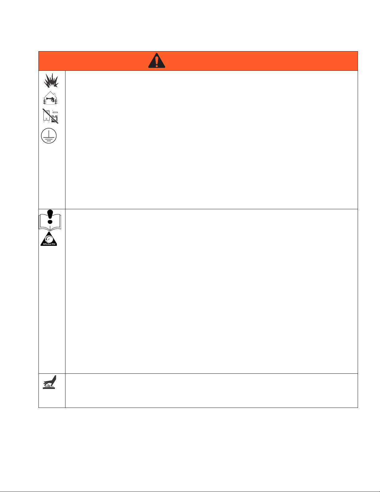
FIRE AND EXPLOSION HAZARD
Flammable fumes, such as solvent and paint fumes, in work area can ignite or explode. To help prevent
fire and explosion:
• Use equipment only in well ventilated area.
• Eliminate all ignition sources; such as pilot lights, cigarettes, portable electric lamps, and plastic drop
cloths (potential static arc).
• Keep work area free of debris, including solvent, rags and gasoline.
• Do not plug or unplug power cords, or turn power or light switches on or off when flammable fumes
are present.
• Ground all equipment in the work area. See Grounding instructions.
• Use only grounded hoses.
• Hold gun firmly to side of grounded pail when triggering into pail.
• If there is static sparking or you feel a shock, stop operation immediately. Do not use equipment
until you identify and correct the problem.
• Keep a working fire extinguisher in the work area.
EQUIPMENT MISUSE HAZARD
Misuse can cause death or serious injury.
• Do not operate the unit when fatigued or under the influence of drugs or alcohol.
• Do not exceed the maximum working pressure or temperature rating of the lowest rated system component. See Technical Data in all equipment manuals.
• Use fluids and solvents that are compatible with equipment wetted parts. See Technical Data in all
equipment manuals. Read fluid and solvent manufacturer’s warnings. For complete information about
your material, request MSDS from distributor or retailer.
• Do not leave the work area while equipment is energized or under pressure. Turn off all equipment
and follow the Pressure Relief Procedure when equipment is not in use.
• Check equipment daily. Repair or replace worn or damaged parts immediately with genuine manufacturer’s replacement parts only.
• Do not alter or modify equipment.
• Use equipment only for its intended purpose. Call your distributor for information.
• Route hoses and cables away from traffic areas, sharp edges, moving parts, and hot surfaces.
• Do not kink or over bend hoses or use hoses to pull equipment.
• Keep children and animals away from work area.
• Comply with all applicable safety regulations.
BURN HAZARD
Equipment surfaces and fluid that’s heated can become very hot during operation. To avoid severe burns:
• Do not touch hot fluid or equipment.
3A0395R 5
Page 6
Important Two-Component Material Information
Important Two-Component Material Information
Isocyanate Conditions
Spraying or dispensing materials containing isocyanates creates potentially harmful mists, vapors, and
atomized particulates.
Read material manufacturer’s warnings and material
MSDS to know specific hazards and precautions
related to isocyanates.
Prevent inhalation of isocyanate mists, vapors, and
atomized particulates by providing sufficient ventilation in the work area. If sufficient ventilation is not
available, a supplied-air respirator is required for
everyone in the work area.
To prevent contact with isocyanates, appropriate personal protective equipment, including chemically
impermeable gloves, boots, aprons, and goggles, is
also required for everyone in the work area.
Material Self-ignition
Some materials may become self-igniting if applied
too thickly. Read material manufacturer’s warnings
and material MSDS.
Keep Components A and B
Moisture Sensitivity of Isocyanates
Isocyanates (ISO) are catalysts used in two component
foam and polyurea coatings. ISO will react with moisture
(such as humidity) to form small, hard, abrasive crystals,
which become suspended in the fluid. Eventually a film
will form on the surface and the ISO will begin to gel,
increasing in viscosity. If used, this partially cured ISO
will reduce performance and the life of all wetted parts.
NOTE: The amount of film formation and rate of crystallization varies depending on the blend of ISO, the
humidity, and the temperature.
To prevent exposing ISO to moisture:
• Always use a sealed container with a desiccant
dryer in the vent, or a nitrogen atmosphere. Never
store ISO in an open container.
• Keep the ISO lube pump reservoir (if installed) filled
with Graco Throat Seal Liquid
206995. The lubricant creates a barrier between the
ISO and the atmosphere.
• Use moisture-proof hoses specifically designed for
ISO, such as those supplied with your system.
• Never use reclaimed solvents, which may contain
moisture. Always keep solvent containers closed
when not in use.
• Never use solvent on one side if it has been contaminated from the other side.
• Always lubricate threaded parts with ISO pump oil
or grease when reassembling.
™
(TSL™), Part
Separate
Foam Resins with 245 fa Blowing Agents
Some foam blowing agents will froth at temperatures
Cross-contamination can result in cured material in
fluid lines which could cause serious injury or damage equipment. To prevent cross-contamination of
the equipment’s wetted parts, never interchange
component A (isocyanate) and component B (resin)
parts.
6 3A0395R
above 90°F (33°C) when not under pressure, especially
if agitated. To reduce frothing, minimize preheating in a
circulation system.
Page 7

Changing Materials
• When changing materials, flush the equipment multiple times to ensure it is thoroughly clean.
• Always clean the fluid inlet strainers after flushing.
• Check with your material manufacturer for chemical
compatibility.
• Most materials use ISO on the A side, but some use
ISO on the B side.
• Epoxies often have amines on the B (hardener)
side. Polyureas often have amines on the B (resin)
side.
Important Two-Component Material Information
3A0395R 7
Page 8
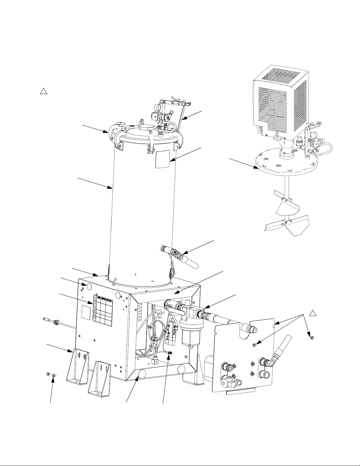
Component Identification
Component Identification
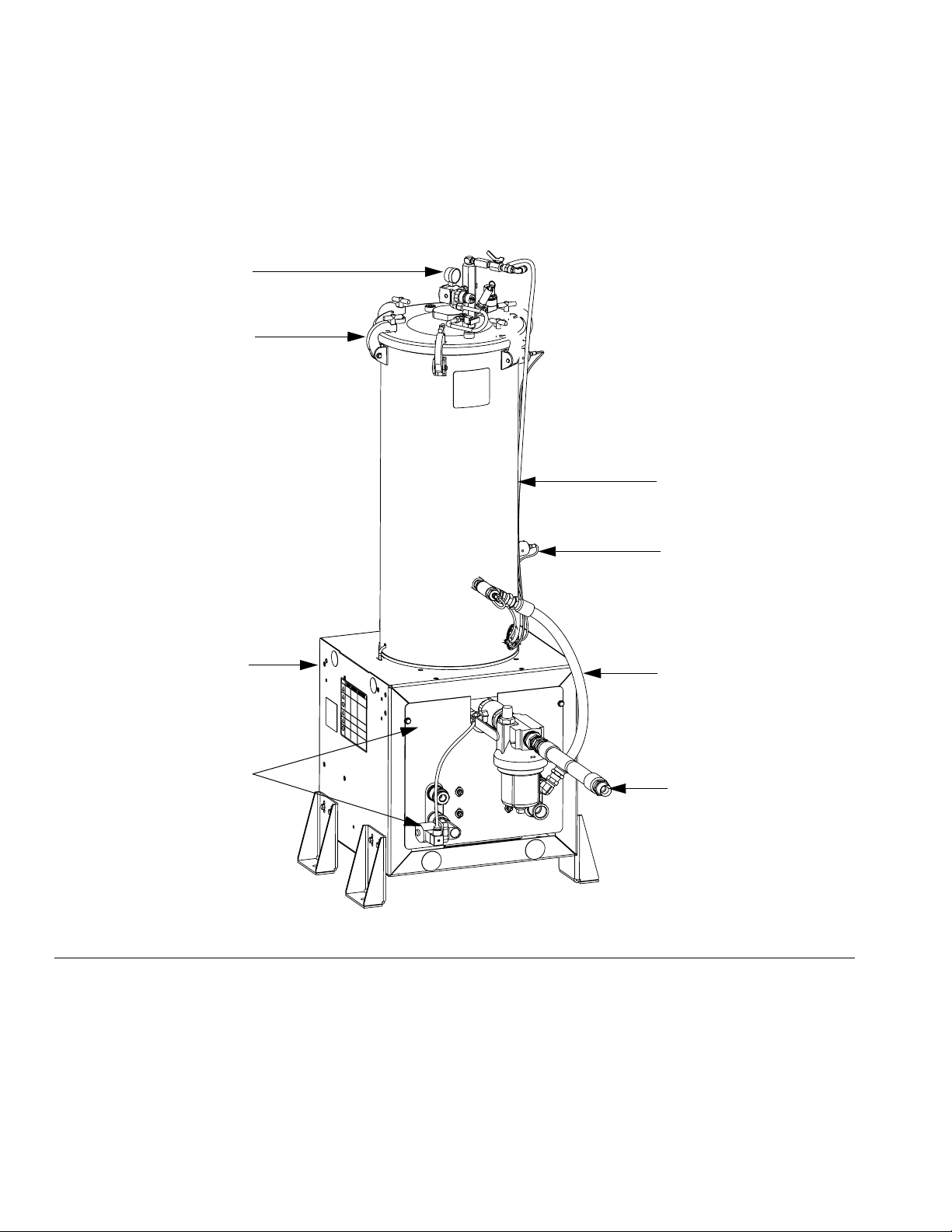
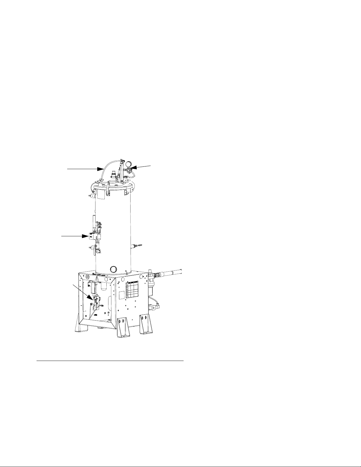
Tank Feed System
A
B
C
H
G
FIG. 1: Component Identification - Tank Feed System
Key:
A Air Pressure Gauge and Valve
B Lid or Lid with Agitator
CTank
D Material Valve
E Recirculation Probe Assembly
F Ball Valve Assembly
G Heat Exchanger Assembly
HEnclosure
J Level Sensors (not shown)
D
E
F
r_24C317_3A0395a_1c
8 3A0395R
Page 9
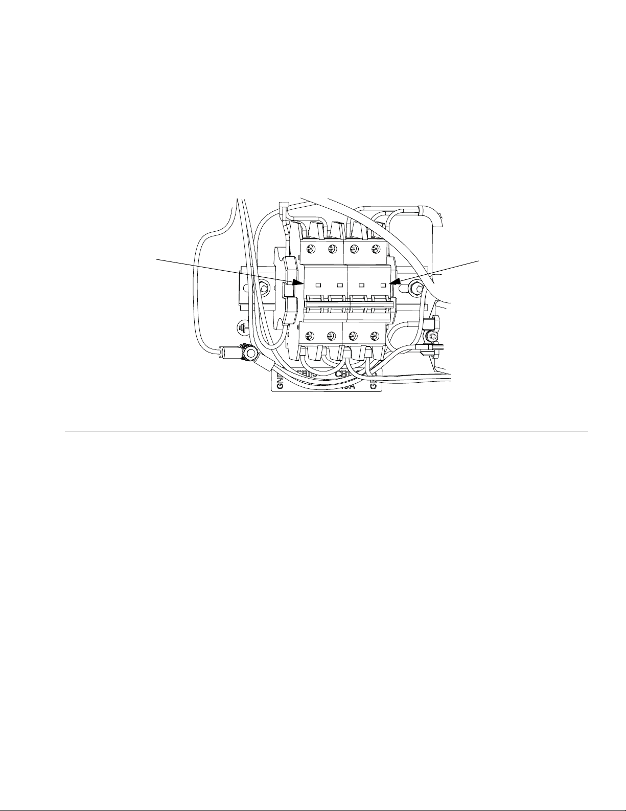
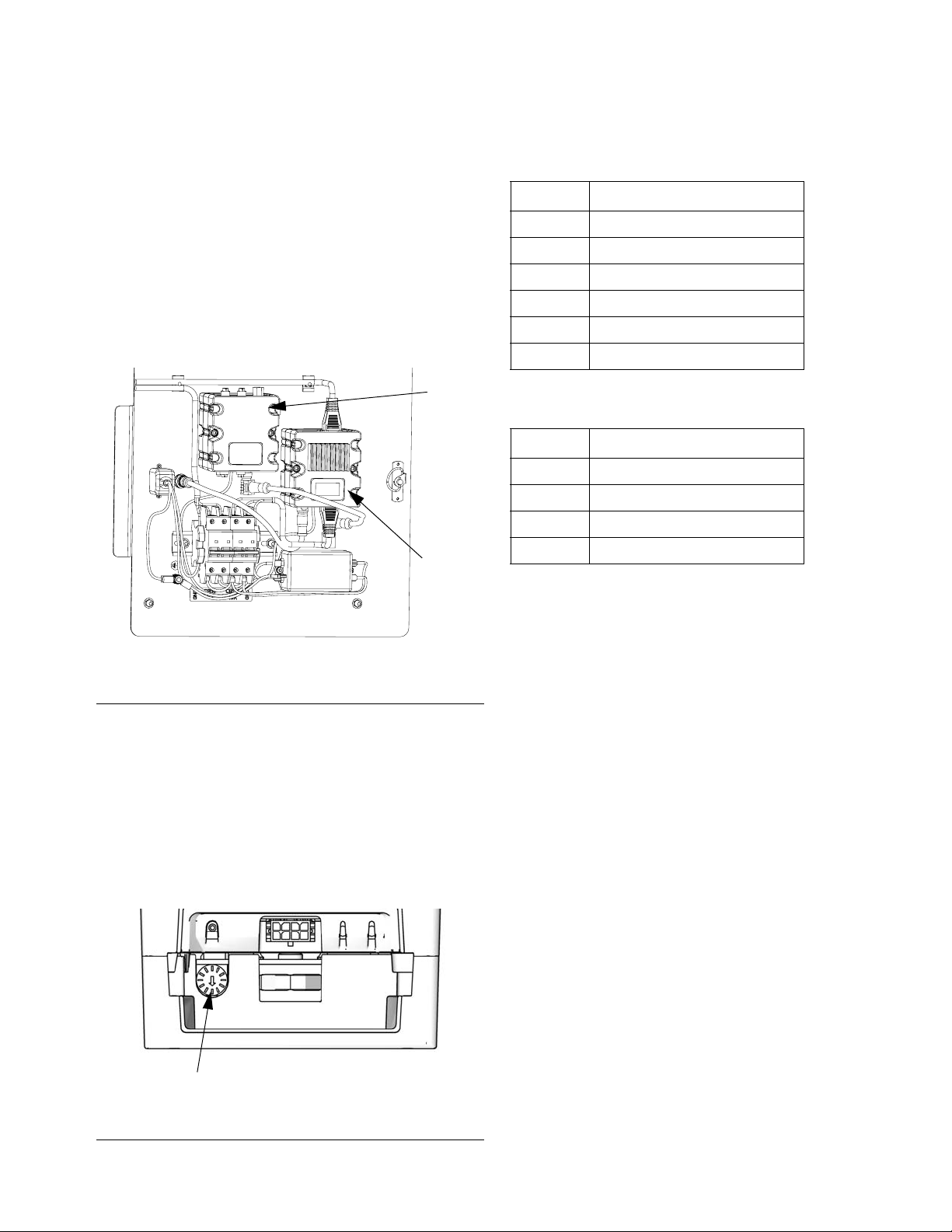
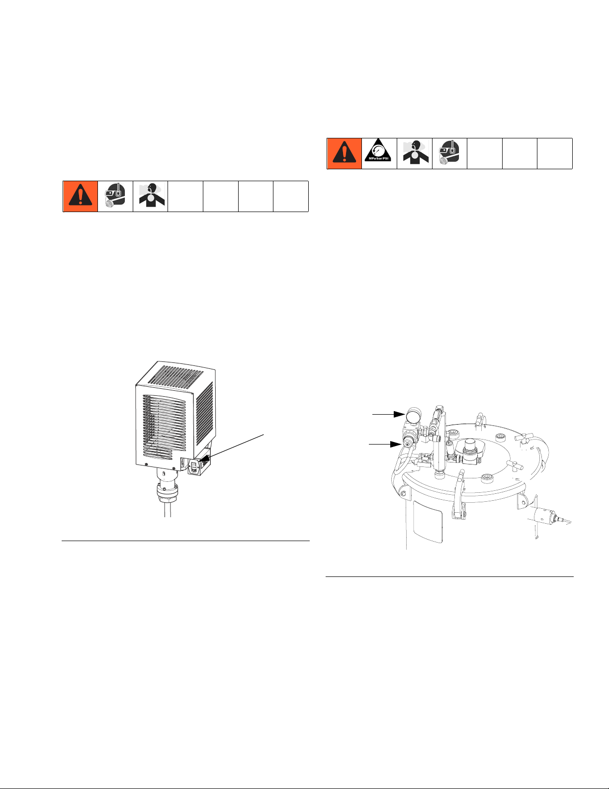
Electrical Panel Components
The electrical panel is located on the inside of the tank
stand enclosure, and includes the circuit breakers, a
fluid control module, and a low power temperature control module.
Circuit Breakers
Component Identification
CB115
FIG. 2: Component Identification - Circuit Breakers
Ref. Size Component
CB115 5A Agitator
CB130 10A Low power temperature control
module / heat blanket / chiller
CB130
3A0395R 9
Page 10
Component Identification
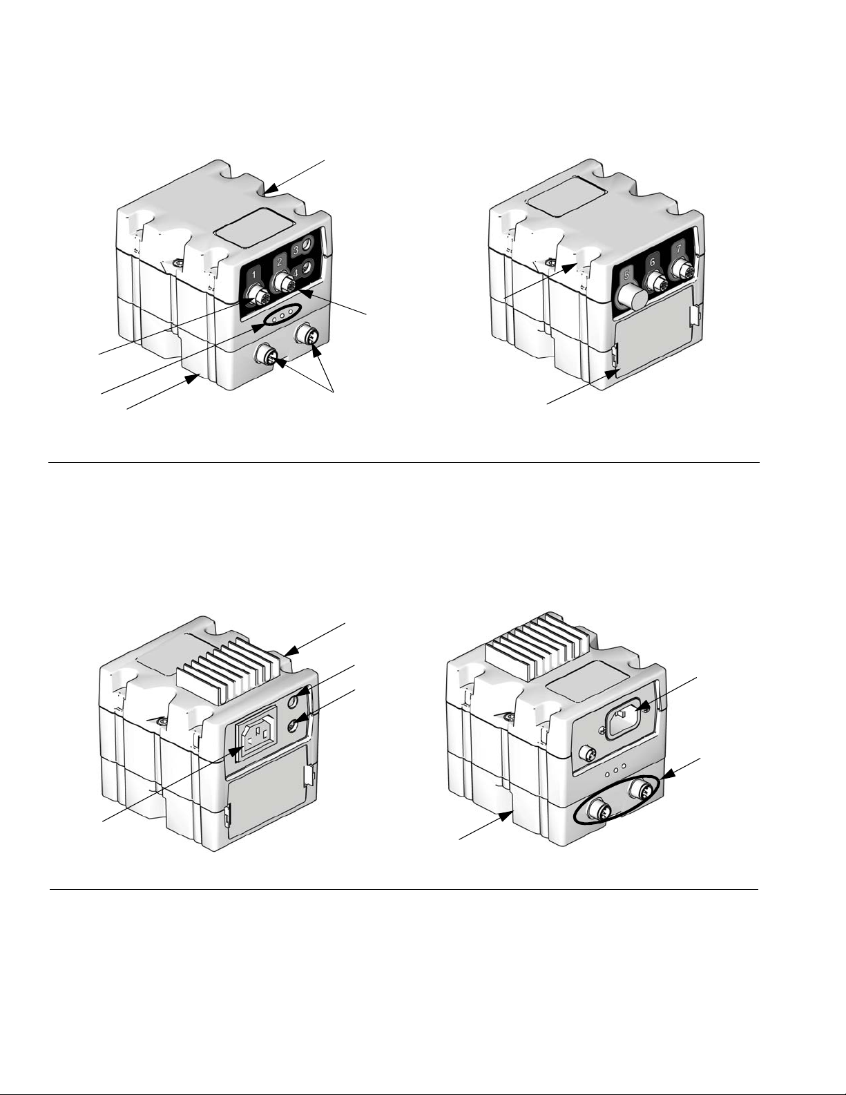
Fluid Control Module (FCM)
AA
AC
AH
AG
AE
ti12337a
AF
AB
FIG. 3: Component Identification - FCM
Key:
AA Fluid Control Module (FCM)
AB Base
AC Module Connection Screws
AD Access Cover
Low Power Temperature Control Module
BA
ti12336a
AD
AE Module Status LEDs
AF CAN Connectors
AG Level Sensor Input
AH Fill Solenoid Signal
BG
BD
BB
BE
BC
ti12356a
BF
ti12357a
FIG. 4: Component Identification - Low Power Module
Key:
BA Low Power Module
BB RTD Temperature Sensor Connection (for chiller or for
RTD in bottom of tank when using a heated blanket)
BC Output Power Connection
10 3A0395R
BD Input Power Connection
BE CAN Connectors
BF Base
BG RTD Temperature Sensor Connection (for RTD under
heated blanket)
Page 11
Component Identification
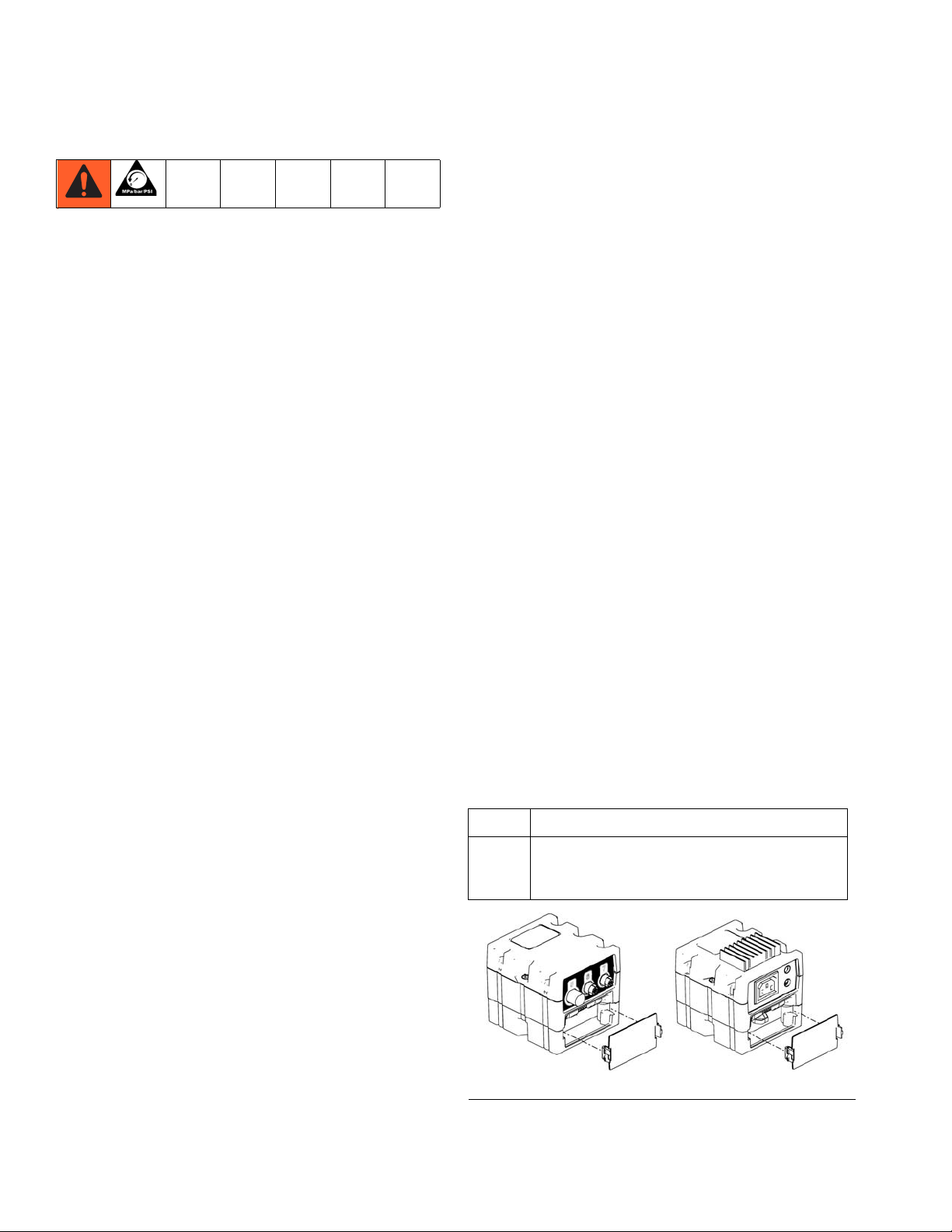
Heat Zone and Fluid Control Selection
The tank feed system supports independent temperature control by utilizing a low power temperature control
module. The system also supports fluid control by utilizing an FCM. Both the low power temperature control
module and the FCM are located on the electrical panel
within the enclosure.
NOTE: Tank stands are configured for the A (Red)
side. Adjust rotary switch setting if tank is being
used on B (Blue) side.
FCM
Low
Power
Te mp
Control
Low Power Temperature Control Module Rotary Switch
Settings
Setting Zone
0-4 Not Used
5 B (Blue) Tank Heater
6 A (Red) Tank Heater
7 B (Blue) Chiller
8 A (Red) Chiller
9-F Not Used
FCM Rotary Switch Settings
Setting Zone
0-2 Not Used
3 B (Blue) Tank Refill
4 A (Red) Tank Refill
5-F Not Used
r_24C169_3A0395_1a
FIG. 5: Electrical Panel
Adjust Rotary Switch
The rotary switch setting indicates which zone the temperature control module will control in the system. The
low power module and FCM use a 16-position rotary
switch to make selections.
Set the rotary switch to the specific selection according
to the settings listed in the following tables.
Rotary Switch
ti12361a
FIG. 6: Adjust Rotary Switch
3A0395R 11
Page 12
Installation
Installation
Grounding
Products that include heated tanks must be grounded.
Grounding reduces the risk of static and electric shock
by providing an escape wire for the electrical current
due to static build up or in the event of a short circuit.
Improper installation of the grounding plug increases the
risk of electric shock. Do not modify the plug provided; if
it does not fit the outlet, have the proper outlet installed
by a qualified electrician. Only connect the product to an
outlet having the same configuration as the plug. Do not
use an adapter with this product.
Install Tank Stand
1. Install the tank stand no more than 6 ft. (1.8 m) from
the rear of the material pumps on the HFR system.
2. Anchor the tank stand to the floor. (Suggested
anchors: McMaster-Carr anchor, 92403A400.) See
Dimensions, page 66.
3. Plug the tank stand power cable into the bottom of
the HFR power distribution box.
4. Plug the tank stand CAN cable into the CAN splitter
inside the distribution box.
NOTE: Tank stands are configured for the A (Red)
side. Adjust rotary switch setting if tank is being
used on B (Blue) side.
Install Barrel Style Level Sensors
1. Turn main power off.
2. Relieve tank air pressure. See Pressure Relief Pro-
cedure, page 17.
3. Drain tanks below the lowest level sensor well.
If installing high temperature level sensors:
4. Apply PTFE paste and PTFE tape to the male
threads of the level sensor.
5. Being careful to not cross-threads, thread the level
sensor (CB) into the corresponding tank port.
NOTICE
To avoid improper operation, ensure the mark (dot
or arrow) found on the hex of the level sensor is
pointing towards the top or bottom of the machine
after tightening.
6. Plug the sensor cable adapter into the level sensor.
7. Plug the sensor connector (CD) into the level sensor
adapter.
8. Plug the sensor connector into the connector on the
FCM.
If installing low temperature level sensors:
NOTE: For proper level sensor function, the tip of
the level sensor well must protrude at least 1/8 in.
into the tank (C).
12 3A0395R
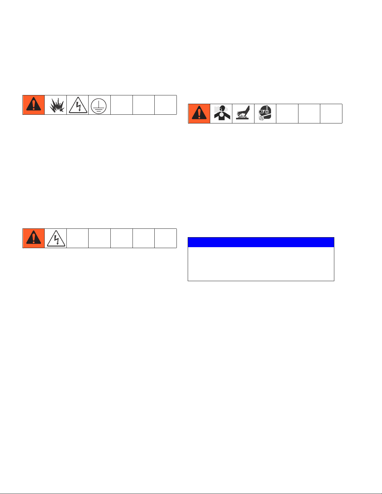
Page 13
Installation
9. Route each level sensor (H) wire (J1, J2, J3)
through the corresponding well nut (CC). See F
IG. 8
for wire location on tank.
CA
CB
CC
Wires
CD
r_24b969_3A0395a_7a
FIG. 7: Level Sensor Assembly
10. Measure the length of the level sensor well housing,
and then measure the depth of the hole in the tank
where the well is inserted. Note these measurements as they will be need later.
11. Being careful to not cross-threads, thread assembled level sensor (CB) into well housing until it bottoms out against the bottom of the well. The bottom
of the level sensor will be slightly visible through the
bottom of the well.
NOTE: In the following step, do not allow PTFE
paste or tape to cover the tip of the level sensor
well. If paste comes in contact with the tip of the
level sensor well, thoroughly wipe it clean.
13. Being careful to not cross-threads, thread the level
sensor well (CA) into the corresponding tank port
and lightly tighten with a crescent wrench.
J3
J2
J1
FIG. 8: Tank Ports
14. Measure the amount of the level sensor well housing that is visible beyond the day tank hole, then
perform the following equation:
P = L1 - (L2 + L3)
P = Protrusion length (inside of day tank)
L1 = Length of level sensor well
L2 = Visible length of level sensor well
L3 = Length of well threads in day tank
15. The protrusion length must be at least 1/8 in.
(3.2 mm). If not, remove the level sensor well and
restart at step 10.
16. Rotate level sensor to optimal position for wire routing.
12. Apply PTFE paste and PTFE tape to the male
threads of the level sensor well housing.
17. Plug the sensor connector (CD) into the level sensors.
Ensure the level sensors are installed in the sensor
well housings before pressurizing the tank. Failing to
do so could cause the well housings to rupture, which
may result in serious injury and material leakage.
18. Plug the sensor connector into the connector on the
FCM.
19. Calibrate the sensor. See Calibrate Barrel Style
Level Sensors, page 16.
3A0395R 13
Page 14
Installation
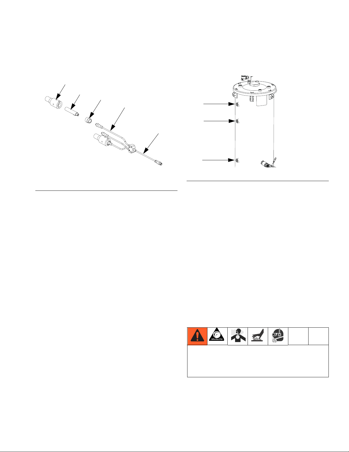
Install Ultrasonic Level Sensor
NOTE: The ultrasonic level sensor is only used on two
gallon tanks.
1. Turn main power off.
2. Relieve tank air pressure. See Pressure Relief Pro-
cedure, page 17.
3. Drain tank.
4. Remove the tank lid (DA).
5. Insert the o-ring (DB) and sensor well housing (DC)
into the tank port.
DE
DC
Install Chiller (customer supplied)
The following instructions apply to tank modules
(24C317, 24D562, 24D564, 24D565) that include the
heat exchanger assembly (G).
NOTE: Graco does not supply the chiller assembly.
1. Connect incoming water to inlet heat exchanger
port.
2. Connect outgoing water to outlet heat exchanger
port.
DB
DA
DD
ti17772a
FIG. 9: Ultrasonic Level Sensor
6. Tighten the jam nut (DD) to ensure there will not be
any air leakage.
7. Hand tighten the level sensor (DE).
8. Plug the sensor connector into the connector on the
FCM.
r_24C317_3A0395a_1c
Water Outlet
FIG. 10: Level Sensor Assembly
3. Configure the advanced display module (ADM) for
the chiller option. See the HFR Setup-Operation
manual for instructions.
Water Inlet
14 3A0395R
Page 15
Installation
Auto-Refill Installation: customer supplied feed system
NOTE: The auto-refill assembly is not assembled
when shipped.
1. Empty tank (C).
2. Remove plug from lower, rear of tank.
3. Install auto-refill assembly in 3/4 npt port.
4. Connect hose (not supplied) to 1/2 npt port on
material valve.
Air Valve
Air Line
Auto-Refill Installation: Graco supplied feed system
NOTE: The auto-refill assembly is not assembled
when shipped.
1. Empty tank (C).
2. Remove plug from lower, rear of tank.
3. Connect feed pump outlet hose to tank.
4. Connect air lines from air valve to feed pump.
5. Connect main air line to air valve.
Material
Valve
Air Solenoid
Valve
r_24C317_3A0395a_10b
FIG. 11: Tank Assembly
5. Connect air lines from air valve (A) to material valve
(D).
6. Connect main air line to air valve.
3A0395R 15
Page 16

Setup
Setup
Calibrate Barrel Style Level Sensors
NOTE: Calibration is not required for ultrasonic
style level sensors or high temperature level sensors.
1. Locate the calibration button on the sensor (11)
closest to the electrical connector through one of
the four holes of the sensor well housing (CA).
2. If the calibration button cannot be seen through one
of the four holes in the sensor well, rotate the sensor.
a. Loosen the sensor well nut (CC).
b. Rotate sensor until the calibration button can be
seen through one of the four holes in the sensor
well housing.
2. Close the shut-off ball valves at the base of the
tanks.
3. If the tank lid has a fill port, turn off any systems that
might refill the tank during the vacuum de-gas procedure.
4. Close the fill port ball valve.
5. If the tank lid requires a desiccant dryer, install it into
the top ball valve of the vacuum tree manifold.
6. Close the top ball valve of the vacuum tree manifold.
7. Attach vacuum pump to the bottom ball valve of the
vacuum tree manifold. Open the ball valve.
8. Turn on the vacuum pump.
9. Continue to de-gas the material.
10. Close bottom ball valve of the vacuum tree manifold.
11. Turn off the vacuum pump.
12. Open the top ball valve of the vacuum tree manifold.
c. Tighten sensor well nut.
d. Press and hold the button down with the ball
end of an allen wrench for two seconds. The
light will flash slowly and then go out.
3. Test for proper sensor function.
a. Loosen the sensor well nut.
b. Back the sensor out of the well. The sensor
should sense the tank wall.
Vacuum De-gas
NOTE: Only perform the following procedures for
tank volumes other than two gallons.
1. Shut down the HFR system. Refer to the HFR
Setup-Operation manual for instructions.
NOTICE
Operating the tank after the vacuum de-gas procedure without the top ball valve open will result in
pump cavitation, off-ratio conditions, and possible
collapse of the tank.
13. Open the shutoff valves at the base of the tanks.
16 3A0395R
Page 17
Operation
Operation
See HFR Setup-Operation manual for system operation
instructions.
Startup
Start System
See HFR Setup-Operation manual for system startup
instructions.
Start Agitation
Press agitator manual switch on and off to start agitation.
Pressure Relief Procedure
NOTE: Relieving air pressure in the machine means
that the supplied dry air will be replaced by moist
air. Do not leave the machine exposed to moist air
for more than 30 minutes. If the machine must be
left without air pressure for more than 30 minutes,
the day tanks must first be emptied and thoroughly
flushed.
1. Turn off main power.
2. Close day tank incoming air supply valve.
3. Disconnect pressurized air supply hose from water
separator.
4. Open the pressure relief valve on top of each day
tank to bleed air pressure from system.
FIG. 12: Agitator Switch
ti17620a
Switch
Pressure
Gauge
Pressure
Relief
Valve
FIG. 13: Tank Pressure Relief
5. Ensure there is no air pressure in the tanks; look at
the pressure gauges.
3A0395R 17
Page 18
Maintenance
Maintenance
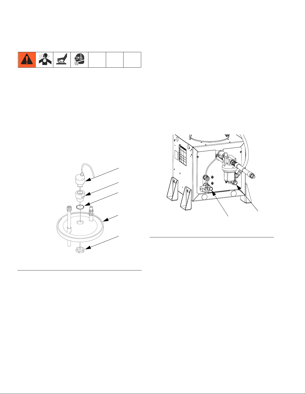
Daily Maintenance
Desiccant Dryer
Replace silica gel units when the desiccant color or
moisture indicator has changed color from Blue (meaning dry) to Pink (meaning wet).
1. Turn off and depressurize the line containing the
dryer unit.
2. Loosen the camp ring and remove the bowl from the
top housing.
3. Pour out used desiccant.
4. Open new container and refill bowl
5. Shake or tap bowl to settle desiccant. Add or
remove desiccant until it is 1/8 in. below the inner
step of the bowl.
Air Filter (123377)
1. Drain water separator if necessary.
2. Pressurize the air system.
3. If desired, place a container underneath water separator to catch water.
4. Push purge valve.
5. Release valve when filter is empty.
Replacement Filters
• 108111 – 30 stainless steel mesh
• 108112 – 60 stainless steel mesh
• 108113 – 100 stainless steel mesh
• 108114 – 200 stainless steel mesh
• 108115 – 150 stainless steel mesh
Install Upgrade Tokens
NOTE: The Fluid Control Module and Temperature Con-
trol Module connection to the system is temporarily disabled during the installation of upgrade tokens.
To install software upgrades:
1. Use correct software token stated in the table. See
Graco Control Architecture
manual for instructions.
NOTE: Upgrade all modules in the system to the
software version on the token, even if you are
replacing only one or two modules. Different software versions may not be compatible.
All data in the module (System Settings, USB Logs,
Recipes, Maintenance Counters) may be reset to
factory default settings. Download all settings and
user preferences to a USB before the upgrade, for
ease of restoring them following the upgrade.
See manuals for locations of specific GCA components.
The software version history for each system can be
viewed in the technical support section at
www.graco.com.
™
Module Programming
Weekly Maintenance
Material Filter (213062)
The red alert filter indicator provides gradual warning of
a dirty element. When the indicator displays as 3/4 red,
clean the element. If the element is not cleaned
promptly, the filter bypass valve opens and fluid will not
be filtered.
To clean the element:
1. Clean the filter element with a small paint brush.
2. Use air to blow out lodged particles.
3. Inspect for damage.
4. Replace if ruptured. See manual 307283.
18 3A0395R
Token Application
16G584 Tank St and:
- Fluid Control Module
- Low Power Temperature Control Module
ti12334a1
F
IG. 14: Remove Access Cover
ti12358a1
Page 19
Troubleshooting
Problem Cause Solution
Troubleshooting
No agitation. Agitator motor is not turning.
Intermittent electrical connections.
Ensure the system main power is
ON.
Ensure all electrical connections to
the motor are secure. See electrical
schematic in either the HFR
Repair-Parts manual.
Check fuse at agitator switch.
Check if motor circuit breaker in
base cube has tripped. See electrical schematic in either the HFR
Repair-Parts manual.
Check if tank stand circuit breaker in
power distribution module has
tripped. See electrical schematic in
either the HFR Repair-Parts manual.
Replace motor.
No vacuum suction in tank. Vacuum pump is not functioning.
Vacuum lines damaged or leaking.
3A0395R 19
Check power cord from wall.
Ensure vacuum pump power is ON.
Ensure connections from vacuum
line to tank lid are secure.
Ensure there are no kinks or links in
vacuum line to tank lid.
Replace vacuum pump.
Page 20

Troubleshooting
Problem Cause Solution
Material is not heating. Blanket heater not working.
Intermittent electrical connections.
Material temperature variations.
FCM errors.
Ensure the system main power is
ON.
Ensure all electrical connections to
the blanket heater are secure. See
electrical schematic in either the
HFR Repair-Parts manual.
Ensure the tank RTD connections
are secure. See electrical schematic in either the HFR
Repair-Parts manual.
Check if FCM circuit breaker has
tripped. See electrical schematic in
either the HFR Repair-Parts manual.
Check if tank stand circuit breaker in
™
GMS
power distribution box has
tripped. See electrical schematic in
either the HFR Repair-Parts manual.
Check FCM. A red LED indicates a
problem with the module. See electrical schematic in either the HFR
Repair-Parts manual.
Replace tank RTD.
Replace blanket heater RTD.
Replace blanket heater.
Replace FCM
20 3A0395R
Page 21

Problem Cause Solution
Troubleshooting
Material is not cooling. Chiller control solenoid not working.
Intermittent electrical connections.
Material temperature variations.
FCM errors.
Ensure the system main power is
ON.
Ensure all electrical connections to
the chiller control solenoid are
secure. See electrical schematic in
either the HFR Repair-Parts manual.
Ensure the tank RTD connections
are secure. See electrical schematic in either the HFR
Repair-Parts manual.
Check FCM circuit breaker in base
cube to see if it has tripped. See
electrical schematic in either the
HFR Repair-Parts manual.
Check tank stand circuit breaker in
GMS power distribution box to see if
it has tripped. See electrical schematic in either the HFR
Repair-Parts manual.
Check FCM. A red LED indicates a
problem with the module. See electrical schematic in either the HFR
Repair-Parts manual.
Replace tank RTD.
Replace chiller control solenoid.
Replace FCM.
3A0395R 21
Page 22

Troubleshooting
Problem Cause Solution
Level sensor is not sensing material
when material is present.
Level sensor is sensing material
when material is not present.
Level sensors out of calibration.
Level sensors blocked inside tank.
Intermittent electrical connections.
FCM errors.
Ensure the system main power is
ON.
Calibrate level sensor.
Check inside tank to ensure there is
nothing blocking the level sensor.
Ensure all electrical connections to
the level sensor are secure. See
electrical schematic in either the
HFR Repair-Parts manual.
Check FCM circuit breaker in base
cube to see if it has tripped. See
electrical schematic in either the
HFR Repair-Parts manual.
Check tank stand circuit breaker in
GMS power distribution box to see if
it has tripped. See electrical schematic in either the HFR
Repair-Parts manual.
Check FCM. A red LED indicates a
problem with the module. See electrical schematic in either the HFR
Repair-Parts manual.
Replace level sensor.
Replace FCM.
22 3A0395R
Page 23

Problem Cause Solution
Troubleshooting
Tank is not refilling. Air solenoid valve not operating.
Leaking or damaged air lines.
Intermittent electrical connections.
Level sensors out of calibration.
Supply/feed system is off or empty.
Check the material supply feed to
the tank.
Check inside tank to ensure there is
nothing blocking the level sensor.
Ensure the main air to tank connections are secure.
Ensure the air lines from the air
solenoid valve to the fill valve or
feed pump are securely connected
and that there are no leaks.
Ensure all electrical connections to
the air solenoid valve are secure.
See electrical schematic in either
the HFR Repair-Parts manual.
Ensure the air solenoid valve is
operating by removing the outgoing
air line to determine if air is flowing.
Check FCM. A red LED indicates a
problem with the module. See electrical schematic in either the HFR
Repair-Parts manual.
Replace air solenoid valve.
Replace level sensor.
Replace fill valve.
Replace feed pump.
Replace FCM.
3A0395R 23
Page 24

Troubleshooting
Problem Cause Solution
Tank is overfilling. Level sensors out of calibration.
Level sensors blocked inside tank.
Intermittent electrical connections.
Calibrate level sensors.
Check inside tank to ensure there is
nothing blocking the level sensor.
Ensure the main air to tank connections are secure.
Ensure the air lines from the air
solenoid valve to the fill valve or
feed pump are securely connected
and that there are no leaks.
Ensure all electrical connections to
the air solenoid valve are secure.
See electrical schematic in either
the HFR Repair-Parts manual.
Ensure the air solenoid valve is
operating by removing the outgoing
air line to determine if air is flowing.
Check FCM. A red LED indicates a
problem with the module. See electrical schematic in either the HFR
Repair-Parts manual.
Replace air solenoid valve.
Replace level sensor.
Replace fill valve.
Replace feed pump.
Replace FCM.
24 3A0395R
Page 25

Problem Cause Solution
Troubleshooting
System is not circulating material. Bypass valve damaged or not oper-
ating.
Material hoses incorrectly connected.
Material hose leakage.
Ensure the system main power is
ON.
Ensure the main air to tank connections are secure.
Ensure the air lines from the bypass
air solenoid valve to the bypass
valve are securely connected and
that there are no leaks.
Ensure all electrical connections to
the bypass air solenoid valve are
secure. See electrical schematic in
either the HFR Repair-Parts manual.
Ensure the bypass air solenoid
valve is operating by removing the
outgoing air line to determine if air is
flowing.
Check FCM. A red LED indicates a
problem with the module. See electrical schematic in either the HFR
Repair-Parts manual.
Check tank stand circuit breaker in
GMS power distribution box to see if
it has tripped. See electrical schematic in either the HFR
Repair-Parts manual.
Replace bypass valve.
Replace bypass air solenoid valve.
3A0395R 25
Page 26

Troubleshooting
Problem Cause Solution
Tank stand module is not communicating with system.
Intermittent electrical connections.
FCM errors.
Ensure the system main power is
ON.
Ensure power disconnect on base
cube is ON.
Ensure all power and communication connections from the GMS system to the tank stand are secure.
See electrical schematic in either
the HFR Repair-Parts manual.
Check tank stand circuit breaker in
GMS power distribution box to see if
it has tripped. See electrical schematic in either the HFR
Repair-Parts manual.
Check FCM. A red LED indicates a
problem with the module. See electrical schematic in either the HFR o
Repair-Parts manual.
Replace power cable.
Replace communications cable.
26 3A0395R
Page 27

Repair
Repair
Replace Agitator Fuse
1. Turn off main power.
2. Slide open the fuse drawer.
3. Remove old fuse and replace with new fuse.
Fuse Drawer
and Fuse
ti17620a
FIG. 15: Agitator Fuse
Tank Lid Gasket
NOTE: If the tank includes an agitator, use a capable
hoist to lift the tank lid and agitator assembly out of
the day tank.
Tools/Supplies Required:
• Hoist (if an agitator is installed)
• Drop cloth
• Crescent wrench
• 3 ft. x 3 ft. air tight plastic sheet and removable tape
•Screwdriver
• Lithium o-ring grease
1. Turn off main power.
2. Relieve tank air pressure. See Pressure Relief Pro-
cedure, page 17.
3. Use a drop cloth to set the tank lid assembly on.
4. Remove pressurized air supply tubing from tank air
pressure inlet. Press on locking collar and pull out
the tube.
5. Use a crescent wrench to loosen all of the bolts
(CE) on the tank lid (B) in a cross-wise pattern.
3A0395R 27
Page 28

Repair
6. Lift the tank lid assembly (B) off of the tank and set
on the drop cloth.
NOTICE
Damage to the level sensors may occur when there
is an agitator installed and the lid is removed. To
avoid damage to level sensors, remove the tank lid
assembly while keeping the agitator away from the
level sensor assemblies.
CE
B
CG
7. Use an air tight plastic sheet and removable tape to
cover the day tank opening. Tape the sheet in place.
8. Use a screwdriver to remove the tank lid gasket
(CG, part 117571) from the groove on the bottom of
the tank lid.
9. Apply lithium grease to the new tank lid gasket and
press the gasket into the groove.
10. Remove air tight plastic sheet and tape from tank.
11. Replace the tank lid (B) and new gasket onto the
day tank.
12. Hand-tighten the bolts onto the lid. Then use a crescent wrench to tighten the bolts (CE) in a cross-wise
pattern.
13. Re-attach pressurized air supply tubing by pressing
in on locking collar and sliding in the tube.
14. With air pressure now supplied to the tank, purge
the moist air from the tank by opening the air purge
valve on the tank lid for 60 seconds.
FIG. 16: Tank Lid
15. Turn on main power and run the machine for 30 minutes to circulate material.
r_24c317_3A0395a_6a
28 3A0395R
Page 29

Repair
Level Sensor and Well
NOTE: For proper level sensor function, the tip of
the level sensor well must protrude at least 1/8 in.
into the tank (C).
CA
CB
CC
CD
r_24b969_3A0395a_7a
FIG. 17: Level Sensor Assembly
1. Turn main power off.
9. Apply PTFE paste and PTFE tape to the male
threads of the level sensor well housing.
10. Being careful to not cross-threads, thread the level
sensor well into the tank (C) and lightly tighten with
a crescent wrench.
11. Measure the amount of the level sensor well housing that is visible beyond the day tank hole, then
perform the following equation:
P = L1 - (L2 + L3)
P = Protrusion length (inside of day tank)
L1 = Length of level sensor well (A10)
L2 = Visible length of level sensor well
L3 = Length of well threads in day tank
12. The protrusion length must be at least 1/8 in.
(3.2 mm). If not, remove the level sensor well and
restart at step 7.
13. Rotate level sensor to optimal position for wire routing and connect cable to connector.
2. Relieve tank air pressure. See Pressure Relief Pro-
cedure, page 17.
3. Drain tanks to below level sensor well.
4. Unscrew level sensor harness cable (CD) from level
sensor well housing (CA).
5. Use a crescent wrench to remove level sensor
well housing from tank (C).
6. Remove the old level sensor (CB) from well housing.
7. Measure the length of the level sensor well housing,
and then measure the depth of the hole in the tank
where the well is inserted. Note these measurements as they will be needed later.
8. Being careful to not cross-threads, thread assembled level sensor (CB) into well housing until it bottoms out against the bottom of the well. The bottom
of the level sensor will be slightly visible through the
bottom of the well.
NOTE: In the following step, do not allow PTFE
paste or tape to cover the tip of the level sensor
well. If paste comes in contact with the tip of the
level sensor well, thoroughly wipe it clean.
3A0395R 29
Page 30

Electrical Schematics
Electrical Schematics
Electrical Panel, Tank Stand with Agitator, Heater/Chiller
30 3A0395R
Page 31

Continued
Electrical Schematics
3A0395R 31
Page 32

Electrical Schematics
Continued
32 3A0395R
Page 33

Continued
Electrical Schematics
3A0395R 33
Page 34

Electrical Schematics
Electrical Panel, Tank Stand with Agitator
34 3A0395R
Page 35

Continued
Electrical Schematics
3A0395R 35
Page 36

Electrical Schematics
Continued
36 3A0395R
Page 37
Parts
Parts
38L and 75L Tank Modules
1
Mounting screws supplied with assembly.
Front View Shown
2
1
Ref. 4 Shown
4
29
28
19
20, 21
22
43
18
3
24
33, 34
41
5
r_24C317_3A0395a_11b
ti17773a
6
1
3A0395R 37
Page 38

Parts
38L and 75L Tank Modules
1
Mounting screws supplied with assembly.
Rear View Shown
7
26
16
23
17
(within
tank)
22
27
35, 36, 37, 38
12
13
12
13
25
11
10
1
r_24C317_3A0395a_12b
13
15
14
8
13
15
14
38 3A0395R
Page 39

Parts
38L and 75L Tank Module Parts
The following tables on this and the next three pages list the varying part numbers, common part numbers, and quantities by tank module assembly.
Tank Module and Quantity
Ref Part Description
1 ★ TANK, assy, 38L, sst 1 1 1 1 1 1
TANK, assy, 75L, sst 1 1
★ TANK, assy, heat, 38L,
sst
★ TANK, assy, heat, 75L,
sst
2 LID, assy, 38L/75L, rim1111111
★ LID, assy, agitator, vac
degas, fill
3 ENCLOSURE, frame 1 1 1 1 1 1 1 1
4 LID, assy, plug,
38L/75L, rim
★ LID, assy, 38L,
agitator, rim
LID, assy, 75L,
agitator, rim
5 VALVE, assy, ball; 1-1/2
npt, sst
★ VALVE, assy, ball; 1-1/2
npt, sst
6 24D852★ COVER, assy, tank
stand
EXCHANGER, assy,
heat, tank, single
7 ★ COVER, enclosure,
slotted, assy
PANEL, assy, electric,
tank, agit/heat
★ PANEL, assy, electric,
tank, agit
8 24C157 VALVE, assy, power,
tank, transfer pump
10 FILTER, dryer, assy,
tank
11 SWITCH, assy, level, 2
prox
12 117683 SCREW, mach, pan
head
13107016WASHER, plain 88888888
14 100072 NUT, hex mscr 4 4 4 4 4 4 4 4
15100079WASHER, lock, spring44444444
24C317 24D562 24D564 24D565 24D568 24D569 24D570 24D571
1
1 111
1 11
1
1 1 1 1
1 1 1 1
1111
1111
1
1 1 1 1
1 1 1
1111
1 1 1 1 1 1 1 1
1111
4 4 4 4 4 4 4 4
111
111
3A0395R 39
Page 40

Parts
Tank Module and Quantity
Ref Part Description
16 FITTING, assy,
bulkhead; 1/4 npt
17 GUARD, trim, edge 2929292929292929
18 PROBE, assy, recircula-
tion, heat exchange
1924D021BRACKET, anchor 44444444
20 111800 SCREW, cap, hex head 8 8 8 8 8 8 8 8
22123398PLUG, hole; 1.5 in. dia.55556555
23 123679 BUSHING, wire protec-
tor, snap-in
24123590PLUG, hole; 2 in. dia.22222222
25 123944 HARNESS, power cord,
tank stand; 20A
26 124003 CABLE, CAN,
male-female, 5 m
27 122005 BUSHING, strain relief 1 1 1 1 1 1 1 1
28 257606 PLATE, slinger, 38L/75L
2915G476LABEL, identification11111111
30★ 123395 HARNESS, power,
valve
33100015NUT, hex 33333333
34 100985 WASHER, lock 4 4 4 4 4 4 4 4
35116610SCREW, mach, pan4444
36 123452 HOLDER, anchor 4 4 4 4 4 4 4
37100020WASHER, lock 4444
38 100016 NUT, full hex 4 4 4 4 4 4 4
41▲ 196548LABEL, caution 11111111
43▲ 15M511 LABEL, warning 1 1 1 1 1 1 1 1
24C317 24D562 24D564 24D565 24D568 24D569 24D570 24D571
1 1 1 1 1 1 1 1
1 1 1 1
3 3 3 3 2 2 2 2
1 1 1 1 1 1 1 1
11111111
1
1 1 1 1
444
444
★ Not shown.
▲ Replacement Danger and Warning labels, tags, and
cards are available at no cost.
40 3A0395R
Page 41

38L and 75L Tank Module Parts (continued)
Parts
Tank Module and Quantity
Ref Part Description
1 ★ TANK, assy, 38L, sst
TANK, assy, 75L, sst 1 1 1 1
★ TANK, assy, heat, 38L,
sst
★ TANK, assy, heat, 75L,
sst
2 LID, assy, 38L/75L, rim
★ LID, assy, agitator, vac
degas, fill
3 ENCLOSURE, frame 1 1 1 1 1 1 1 1 1
4 LID, assy, plug,
38L/75L, rim
★ LID, assy, 38L,
agitator, rim
LID, assy, 75L,
agitator, rim
5 ★ VALVE, assy, ball; 1-1/2
npt, sst
6 24D852 COVER, assy, tank
stand
EXCHANGER, assy,
heat, tank, single
7 ★ COVER, enclosure,
slotted, assy
PANEL, assy, electric,
tank, agit/heat
★ PANEL, assy, electric,
tank, agit
8 24C157 VALVE, assy, power,
tank, transfer pump
10 FILTER, dryer, assy,
tank
11 SWITCH, assy, level, 2
prox
24F519★KIT, level sensor, high
temperature
12 117683 SCREW, mach, pan
head
13107016WASHER, plain 888888888
14 100072 NUT, hex mscr 4 4 4 4 4 4 4 4 4
15100079WASHER, lock, spring444444444
24D572 24D573 24D574 24D575 24D576 24D577 24D578 24D579 24P091
1 1
1 1 1
1111 11
1
11
11
11111
1 1 1 1 1 1 1 1 1
111111111
1
1 1 1 1 1
1 1 1
11 111111
1 1 1 1 1 1 1 1 1
11
4 4 4 4 4 4 4 4 4
11111
11
3
3A0395R 41
Page 42

Parts
Tank Module and Quantity
Ref Part Description
16 FITTING, assy,
bulkhead; 1/4 npt
17 GUARD, trim, edge 292929292929292929
18 PROBE, assy, recircula-
tion, heat exchange
1924D021BRACKET, anchor 444444444
20 111800 SCREW, cap, hex head 8 8 8 8 8 8 8 8 8
22123398PLUG, hole; 1.5 in. dia.556555555
23 123679 BUSHING, wire protec-
tor, snap-in
24123590PLUG, hole; 2 in. dia.222222222
25 123941 HARNESS, power cord,
tank stand; 20A
26 124003 CABLE, CAN,
male-female, 5 m
27 124005 BUSHING, strain relief 1 1 1 1 1 1 1 1 1
28 257606 PLATE, slinger, 38L/75L 1
29 15G476 LABEL, identification 1 1 1 1 1 1 1 1 1
30★ 123395 HARNESS, power,
valve
33 100015 NUT, hex 3 3 3 3 3 3 3 3 3
34100985WASHER, lock 444444444
35 116610 SCREW, mach, pan 4 4 4 4 4 4 4 4
36 123452 HOLDER, anchor 4 4
37 100020 WASHER, lock 4 4 4 4 4 4 4 4
38 100016 NUT, full hex 4 4
41▲ 196548 LABEL, caution 1 1 1 1 1 1 1 1 1
43▲ 15M511 LABEL, warning 111111111
44★ 123394 HARNESS, sensor,
level, tank, (3)
24D572 24D573 24D574 24D575 24D576 24D577 24D578 24D579 24P091
1 1 1 1 1 1 1 1 1
3 3 3 3 3 3 3 3 3
1 1 1 1 1 1 1 1 1
111111111
11
1
444444
444444
1
★ Not shown.
▲ Replacement Danger and Warning labels, tags, and
cards are available at no cost.
42 3A0395R
Page 43

2 Gallon Tank Module - 24J243
Parts
526
500A
500D
598
500E
500F
500C
599
596
518
500B
500d
520
519
517
518
527
583
521
505
597
596
515
519
590
508
511
507
516
518
523
522
526
513
512
503
504
524
543
503
592
533
532
503
501
529
528
527
530
591
534
587
591
536
536
514
583
546
553
577
539
540
541
565
566
542
533
568
595
594
554
570
3A0395R 43
593
ti17775b
Page 44

Parts
2 Gallon Tank Module (continued)
544
556
553
548
567
547
549
550
545
549
551
552
561
553
578
575
569
555
572
573
575
574
571
575
578
573
ti7774a
577
44 3A0395R
562
563
Page 45

Parts
2 Gal Tank Module (continued)
Ref. Part Description Qty.
501 236086 TANK, pressure assy, 2 gal 1
502 125312 PACKING, o-ring 1
503 16H698 ADAPTER, sensor, ultrasonic 1
504 188784 NUT, jam, hex 1
505 156849 PIPE, nipple 1
506 189016 MANIFOLD, air, inlet 1
507 100030 BUSHING 1
508 110476 ADAPTER, union, straight
swivel
509 110475 FITTING, street, tee 1
510 101759 FITTING, drain cock 1
511 151519 FITTING, nipple, reducing 1
512 110341 REGULATOR, air 1
513 124339 GAUGE, press, 0-160psi 1
514 100840 FITTING, elbow, street 1
515 100139 PLUG, pipe 1
516 208390 VALVE, ball 1
517 104813 PLUG, pipe 1
518 123256 FITTING, tee, 1/4npt 1
519 123257 FITTING, nipple, hex 2
520 123258 FITTING, valve, bleed 1
521 121021 MUFFLER 1
522 103347 VALVE, safety, 100 psi 1
523 112307 ELBOW, street 1
524 164724 HOSE, coupled 1
525 121089 FITTING, nipple 1
526 121018 FITTING, elbow, male, swivel 1
527 111928 TEE, male branch pipe 1
528 191931 NIPPLE 1
529 114243 VALVE, check 1
530 125214 BUSHING, hex 1
532 125213 ADAPTER, reducer 1
533 112268 SWIVEL, union 2
534 501867 VALVE, check 1
536 262206 FITTING, swivel 2
539 125217 FITTING, nipple 1
540 102325 FITTING, elbow, 90 degrees 1
541 125218 FITTING, nipple 1
542 122770 VALVE, ball 1
543 24N004 SENSOR, ultrasonic, pro-
grammed
544 24H179 PANEL, gms, tank, levels only 1
545 24C157 VALVE, assy, pwr, tank, xfer
pump
546 257965 ENCLOSURE, frame, painted 1
547 24C159 FILTER, dryer, assy, tank 1
548 24C228 FITTING, assy, bulkhead, 1
549 107016 WASHER, plain 4
550 117683 SCREW, mach 2
551 100079 WASHER, lock, spring 2
552 100072 NUT, hex mscr 2
553 123398 PLUG, hole, 1.5"dia 5
554 123590 PLUG, hole, 2" dia 4
555 16A221 BRACKET, anchor 4
556 124334 PLUG, hole, 1.375"dia, blk 3
★557 123452 HOLDER, anchor, wire tie, nylon 4
1
1
1
★558 116610 SCREW, mach, phil, pan, #10 4
★559 100020 WASHER, lock 4
★560 100166 NUT, full hex 4
561 123395 HARNESS, pwr valve, tank 1
★564 24D847 HARNESS, ground, tank 1
565 16D782 BLANK, label, kit, 3x3 1
▲567 196548 LABEL, caution 1
▲568 15M511 LABEL, warning, eng/span/fre 1
569 111800 SCREW, cap, hex hd 8
570 24D852 COVER, assy, tank stand, blank 1
571 16H696 PLATE, mtg, tank, 2gal 2
572 125221 BOLT, "j", 1/4-20 2
573 112689 SCREW, button hd 4
574 100016 WASHER, lock 3
575 100527 WASHER, plain 5
▲577 15G476 LABEL, a-b identification 2
578 100015 NUT, hex mscr 3
★580 123673 HARNESS, ext, m12xm12 1
581 123424 GUARD, trim, edge 2.5
582 185531 TUBE, siphon 1
583 235208 FITTING, union, swivel 1
584 155665 UNION, adapter 1
585 24C656 HOSE, coupled, 10 ft, sst 1
586 166866 FITTING, elbow, street, sst 1
587 124962 FITTING, tee 1
590 125848 VALVE, check, 1/4 npt, 250 psi,
brass
591 121907 FITTING, nipple, hex, 1/4 npt,
stainless steel, swivel
592 126135 HARNESS, M12xM12, 8-pin x 5
pin, female x male, 1.5 meter
593 24N437 BRACKET, filter, 2 gallon tank 2
594 100057 SCREW, cap, hex head 2
595 112904 WASHER, lock, spring 2
596 217430 FITTING, swivel, union, 90
degree
597 100081 BUSHING, pipe 1
598 156971 FITTING, nipple, short 1
599 6311-381 VALVE, 1/4 ball valve with relief 1
500A 6312-74 MUFFLER, silencer 1
500B 126302 VALVE, chemical relief 1
500C 16F259 FITTING, run tee, 3/4 npt 1
500D 122327 FITTING, elbow, street 1
500E 123376 FITTING, tee, run, 1/4 tube x
1/4 npt, brass
500F 100615 BUSHING, hex steel 1
1
2
1
2
1
★ Not shown.
▲Replacement Danger and Warning labels, tags, and
cards are available at no cost.
3A0395R 45
Page 46

Parts
Heated Tank Assemblies
38L and 75L Heated Tank Assemblies
50
Ref. Part Description Qty.
50 TANK, assy. 1
✓257762 38L, SST
◆257772 75L; SST
51 INSULATOR, blanket assy. 1
✓257757 38L
◆257758 75L
52 BLANKET, assy., heat 1
✓257760 38L, 240V
◆257761 75L, 240V
53 257759 SENSOR, thermowell assy., RTD 1
54 256611 SENSOR, assy.; 1.5 in., RTD, 4-pin m81
52
61
60
55
59
51
54
53
58
55 256558 SWITCH, assy., thermal; 125c, 3p, m81
56 121615 HARNESS, splitter; m8, 4-pin ffm, 3m1
57 121682 CABLE; m8, 3-pin, mf, 3 meter,
molded
58 121599 CORD, power, v-lock; c14/c13,10A 1
59 24D847 HARNESS, ground, tank 1
60 124270 TAPE, fiberglass; 6 ft. 61 261076 TIE, hose lacing; 6 ft. -
✓ 38L heated tank assemblies only.
◆ 75L heated tank assemblies only.
1
56
57
ti7043a
46 3A0395R
Page 47

Parts
Tank Lid Assemblies
Lid with Agitator
101f,
101e,
101t
101c,
101d
101h
101j
101i
101j
101m
101l
101r,
101s
101g
101l
101n
101x,
101y,
101aa
101m
101o
101p
101q
102a
102b
101u
107
109
108
101a
101k
101b
101z
101af
101ag
101z
101v,
101w,
101ab,
101ac,
101ad,
101ae,
103,
104,
105,
106
Lid with agitator for 38L tanks
Lid with agitator for 75L tanks
Ref Part Description Qty
101 257605 HOUSING, agitator 1
. 101a 124741 MOTOR, agitator 1
. 101b 16K267 ADAPTER, plate, agitator
motor
. 101c 158223 WASHER 4
. 101d 108803 SCREW, hex 4
. 101e 100021 SCREW, cap 2
. 101f 122775 NUT, eye, 1/4-20 2
. 101g 15Y358 HOUSING, upper, agitator 1
. 101h 15V746 SPACER, agitator 1
. 101i 122760 COUPLING, alignment 1
. 101j 122761 HOSE, alignment 2
. 101k 101885 SCREW, cap 4
. 101l 122774 BEARING, ball 2
. 101m 15Y360 SPACER, seal, shaft 1
. 101n 122772 SEAL 1
. 101o 15Y357 HOUSING, lower 1
. 101p 15Y363 GASKET 1
. 101q 15Y355 NUT, shaft 1
. 101r 105510 WASHER, lock 4
. 101s 112222 SCREW, cap 4
. 101t 100985 WASHER, lock 2
. 101u 15R328 JUNCTION BOX, motor
switch
. 101v 111307 WASHER, lock 2
. 101w 102598 SCREW, cap 2
. 101x 120910 SOCKET, electrical 1
. 101y 120916 SCREW 2
. 101z 121172 GRIP, cord 2
. 101aa 115142 FUSE, 5.0 amp, time lag 2
. 101ab▲ 125008 LABEL, earth ground 1
. 101ac 121013 SCREW, socket head 1
. 101ad 120993 NUT, hex 3
. 101ae 24H375 HARNESS, ground 1
. 101af 24H376 HARNESS, power 1
. 101ag▲ 15X092 LABEL, 240 volts 1
1702 257608 BLADE, assy 1
. 102a 257604 BLADE, assy, 38L/75L 2
. 102b 15M625 SHAFT, blade assy 1
1703 122776 TERMINAL, ring 1
1704 124436 CAP, splice 3
1705 124437 CONNECTOR, splice 3
1706 124442 TERMINAL, ring 1
1707 24K356 COVER, motor 1
1708 116876 WASHER 4
1709 102598 SCREW, cap 4
1
1
▲ Replacement Danger and Warning labels, tags, and
ti17777a
3A0395R 47
cards are available at no cost.
Page 48

Parts
Lid Assembly
153
149
150
151
152
142
146
148
163
155
154
147
144
141
158
166
162
158
157
143
r_24B967_3A0395a_1a
156
159
164
165
161
160
141
Ref. Part Description Qty.
141 15M621 LID, agitator 1
142 111384 PLUG, pipe 2
143 159239 NIPPLE, pipe 1
144 189016 MANIFOLD, air, inlet 1
145 100030 BUSHING 1
146 110475 FITTING, street, tee 1
147 101759 FITTING, drain 1
148 110476 ADAPTER, union, straight swivel 1
149 151519 NIPPLE, reducing 1
150 110341 REGULATOR, air 1
151 112307 ELBOW, street 1
152 164724 HOSE, coupled 1
153 124339 GAUGE, pressure, air 1
154 100840 ELBOW, street 1
155 100139 PLUG, pipe 1
156 208390 VALVE, ball 1
157 123256 FITTING, tee; 1/4 npt 1
158 123257 NIPPLE, hex; 1/4 npt 2
159 123258 VALVE, bleed; 1/4 npt 1
160 121021 MUFFLER; 1/4 npt 1
161 103347 VALVE, safety; 100 psi 1
162 104813 PLUG, pipe 1
163 100361 PLUG, pipe 1
164 121089 COUPLING; 1/4 npt, f-f 1
165 121018 ELBOW, male, swivel; 1/4 npt 1
166 125848 VALVE, check, 1/4npt 1
48 3A0395R
Page 49

Plug Assembly for Lid Vacuum Degas Lid Assembly
Parts
171
172
173
r_24B967_3A0395a_1b
Ref. Part Description Qty.
171 16A354 PLUG 1
172 15Y363 GASKET, mounting 1
173 15Y355 NUT 1
184
181
2
Apply thread sealant and PTFE thread tape.
183
r_257756_3A0395a_1a
187
185
2
186
182
Ref. Part Description Qty.
181 15M621 LID, agitator 1
182 122767 BUSHING,; 1/2 x 1/4 npt 2
183 103347 VALVE, safety; 100 psi 1
184 257746 KIT, vacuum tree 1
185 124400 GAUGE, pressure/vac 1
186 257602 VALVE, assy., ball, fill; 3/4 SST 1
187 FITTING, assy., inner fill port 1
3A0395R 49
Page 50

Parts
Electrical Panel, 230V for Heat
201
Ref. 210
218
211
229
227
223
203
235
222
202
211
234
237
212
216, 226
231
219
240
206
236
213, 214
215
209
210
228
221
228, 233
r_24C169_3A0395Aa_1b
50 3A0395R
229
230
223
219
220
239
219
228
224
219
228
207
208
Page 51

Electrical Panel, 230V for No Heat
Parts
201
Ref. 210
229
218
223
227
235
203
202
234
237
212
216, 226
231
206
213, 214
236
219, 240
210
215
221
230
228, 233
r_24C307_3A0395_1b
223
220
219
228
239
208
219
228
224
219
228
3A0395R 51
Page 52

Parts
Electrical Panel, 230V for Heat Parts
Electrical Panel, 230V for No Heat Parts
Ref. Part Description Qty.
201 COVER, enclosure 1
202 117644 LATCH, spring, slotted 1
203 102556 RIVET, blind 2
204★ 123352 PLUG, inlet, electric 1
205★ 102410 SCREW, cap socket head 2
206 289697 MODULE, cube, base 2
207❖ 256270 MODULE, low power temp 1
208 289696 MODULE, fluid control 1
209❖ 121597 CABLE, CAN 90 female / 90
female, 0.4 meter
210 121226 CABLE,CAN, male / female,
0.4m
211❖ 24D747 HARNESS, power, cube,
heat/chiller
212 124064 FILTER 1
213 114993 SCREW, machine pan head 2
214 102063 WASHER, lock, ext 2
215 113003 SCREW, cap, socket head 8
216 100015 NUT, hex 2
218 RAIL, mounting, din; 35mm, 6 in. 1
219 112776 WASHER, plain 6
220 ENCLOSURE 1
221 123296 CIRCUIT, breaker; 2P, 5A 1
222❖ 123297 CIRCUIT, breaker; 2P, 10A 1
223 123363 BLOCK, terminal, ground; 10mm 2
224 123381 TRIM, serrated 12
225★ 121612 CONNECTOR, thru; m12, m x f 1
226 100985 WASHER, lock ext 3
227 123351 COVER, inlet 1
228 100166 NUT, full hex 8
229 24C292 HARNESS, ground, strap, cube 2
Ref. Part Description Qty.
230 24D748 HARNESS, power, cube 1
231 24D847 HARNESS, ground, tank 1
232 123944 HARNESS, power cord, tank
stand; 20A
233 124338 CLAMP, harness; 3/8 in., nylon 3
234 24E278 HARNESS, filter, power in 2
235 24E277 HARNESS, power in/ground 2
236 ❖24E279 HARNESS, filter/breaker 2
1
237 LABEL, identification 1
238 24E236 HARNESS, filter/ground 1
1
239▲ 196548 LABEL, caution 1
240 124337 NUT, allen 2
1
★ Not shown.
▲ Replacement Danger and Warning labels, tags, and
❖ Included in electrical panel for heat only.
† Included in electrical panel for no heat only.
†24E346 HARNESS, filter/breaker, single
cards are available at no cost.
1
52 3A0395R
Page 53

Parts
3A0395R 53
Page 54

Parts
Electrical Panel, 230V for 2 Gallon Tanks Only
503
519
517
518
504
520
521
501
502
524
505
510
506
508
516
509
507
511
525
522
523
513
515
512
514
ti7778a
54 3A0395R
Page 55

Ref. Part Description Qty.
501 24C116 COVER, enclosure, electrical, tank 1
502 117644 LATCH, spring, slotted 1
503 102556 RIVET, blind 2
504 121612 CONNECTOR, thru, m12, mxf 1
505 289697 MODULE, gca, cube, base 1
506 289696 MODULE, gca, cube, fcm 1
507 24H240 HARNESS, wire, ground, term, 9" 1
508 102063 WASHER, lock, ext 1
509 114993 SCREW, mach, pan wash hd 1
510 102598 SCREW, cap, socket head 4
511 100985 WASHER, lock ext 3
512 24C115 ENCLOSURE, elec, tank stand 1
513 112776 WASHER, plain 4
514 123381 TRIM, serrated 2
515 100166 NUT, full hex 4
516 121226 CABLE, can, male / female, 0.4m 1
517 121000 CABLE, can, female / female 0.5m 1
518 124005 BUSHING, strain relief 1
519▲ 16D656 LABEL, identification, electronics 1
520 24H241 COVER, electrical 1
521 15U075 SCREW, cap, bh, 8-32 x .37 2
522 100015 NUT, hex mscr 2
523▲ 196548 LABEL, caution 1
524 277674 ENCLOSURE, cube door 1
525 24D847 HARNESS, ground, tank 1
▲ Replacement Danger and Warning labels, tags, and
cards are available at no cost.
Parts
3A0395R 55
Page 56

Parts
Heat Exchanger Assembly
255
251
266
266
268
264
256
262
257
252
253
264
254
2
Apply thread sealant and PTFE thread tape to all male npt threads as needed.
Ref. Part Description Qty.
251 123072 EXCHANGER, heat, tank, 0.50
1
plates
252 123071 COUPLING, pipe; 1 in. npt, ff 2
253 123073 NIPPLE, hex; 1 in. npt x 3/4 in. npt 1
254 123028 VALVE, solenoid; 240V 1
256 123998 ELBOW; 3/4 in. npt x 3/4 in. nps,
1
m x f
257 513299 BUSHING, reducer 1
261 123093 HARNESS, valve, chiller; 230V 1
262 COVER, enclosure, heat exchange 1
264 123996 COUPLING, 1 in. npt, sst 2
266 111800 SCREW, cap, hex head 2
267 123997 ADAPTER, 1 in. npt x 3/4 in. npt,
1
m x f, sst
268 221170 HOSE, coupled; 3 ft 1
267
252
261
r_257968_3A0395Aa_1a
56 3A0395R
Page 57

Air Dryer Filter
Parts
285
284
283
282
281
289
290
291
292
2
Apply thread sealant and PTFE thread tape to all male npt threads as needed.
293
Ref. Part Description Qty.
281 121019 ELBOW, male, swivel; 3/8 npt 1
282 123377 FILTER, air; 3/8 npt 1
283 123379 FITTING, reducer; 3/8 npt x 1/4 npt 1
284 104984 FITTING, tee, pipe 1
285 156971 NIPPLE, short 1
286 DRYER, air, with desiccant; 1/4 npt 1
287 121018 ELBOW, male, swivel; 1/4 npt 2
288 123376 FITTING, tee, run; 1/4 tube x 1/4
1
npt
289 123380 BRACKET, filter, air; 3/8 npt 1
290 112944 SCREW, cap, button head 2
291 107194 WASHER, plain 2
292 100214 WASHER, lock 2
293 111303 NUT, hex 2
295★ 054106 TUBE, PET; 0.375 OD -
287
286
287
r_24C159_3A0395Aa_1a
★ Not shown.
3A0395R 57
Page 58

Parts
Ball Valve Assemblies
Ball Valve Assembly
301
302
301
303
302
303
304
305
306
307
308
309
2
Apply thread sealant and PTFE thread tape to all male npt threads as needed.
Ball Valve Assembly with Filter
304
305
306
r_24E107_3A0395Aa_1a
310
311
307
308
r_257742_3A0395Aa_1a
309
Ref. Part Description Qty.
301 121136 BUSHING, hex; 2 in. npt x 1-1/2 in. npt 1
302 123001 NIPPLE; 1-1/2 x 6 in., sst 1
303 123003 ELBOW; 1-1/2 x 1-1/2, f x f, sst 1
304 123000 NIPPLE; 1-1/2 x 10 in., sst 1
305 121135 VALVE, ball; 1-1/2 npt full port 1
306 123002 BUSHING; 1-1/2 npt x 1-1/4 npt 1
307 123348 BUSHING; 1-1/4 npt x 1 npt, mf 1
308 123349 FITTING, union, swivel; 1 npt, mf, sst 1
309 24E024 HOSE, tank to system 1
309 24P094 HOSE, coupled, 72L, 1ID, 1NPT, SST
(Assembly 24P091 only)
310 123346 NIPPLE, close; 1-1/4 npt, sst (with filter
version only)
311 213062 FILTER, fluid (with filter version only) 1
1
1
58 3A0395R
Page 59

Recirculation Probe Assembly
326
2
324
327
2
321
322
2
Parts
2
Apply thread sealant and PTFE thread tape.
2
325
328
Ref. Part Description Qty.
321 166466 FITTING, tee, pipe, female 1
322 124280 BUSHING; 3/4 npt x 1/4 npt 1
324 121478 FITTING, compression; 3/16 x 1/4
npt
325 124233 SENSOR, RTD, 4 pin; 1kohm, 4.25
in.
326 123082 FITTING, swivel; 3/4 nps x 3/4 npt 1
327 119992 FITTING, pipe, nipple; 3/4 x 3/4 npt 1
328 121686 CABLE, CAN; m8 x m8, 4P 1
r_24C156_3A0395A_2
1
1
3A0395R 59
Page 60

Parts
Transfer Pump Valve, 24C157
331
332
333
332
r_24C157_3A0395Aa_1b
Ref. Part Description Qty.
331 120900 VALVE, solenoid, 3 way 1
332 121021 MUFFLER; 1/4 npt 2
333 121018 ELBOW, male, swivel; 1/4 npt 2
334 100721 PLUG, pipe 1
333
334
60 3A0395R
Page 61

Accessories and Kits
Accessories and Kits
Level Switch Assembly, 24D271
Third level sensor proximity switch option.
410
403
401
Ref. Part Description Qty.
401 16A511 HOUSING, well, proximity 1
402 121511 SENSOR, capacitive, 18 mm 1
403 16A512 NUT, well, proximity 1
410 123394 HARNESS, sensor, level, tank, (3) Ref
402
r_24D271_3A0395Aa_1a
High Temperature Level Sensor, 24F519
Vacuum Tree Kit, 257746
Connection kit to add vacuum to the tank.
408
407
406
405
r_257746_3A0395Aa_1a
Ref. Part Description Qty.
405 122844 FITTING, tee; 3/4 npt(m), 3k, sst 1
406 122770 VALVE, ball; 3/4 npt(f), 2k, sst 2
407 122769 COUPLING, full; 3/4 npt, sst 1
408 121116 ELBOW; 3/4 npt(m) 1
461
462
Ref. Part Description Qty.
461 125325 HARNESS, M12 x M12 1
462 16H657 SENSOR, level, vibrating 1
3A0395R 61
ti17779a
Page 62

Accessories and Kits
Supplied Feed Refill Kit, 257770
Refill kit for customer-supplied feed systems.
415
414
417
r_257770_3A0395Aa_1b
Ref. Part Description Qty.
410 121116 ELBOW; 3/4 npt(m) 1
411 122770 VALVE, ball; 3/4 npt(f), 2k, sst 1
412 15T005 ADAPTER; 5/8-18 to 3/4 npt, sst 1
413 244910 VALVE, endure 1
414 054130 TUBE, PET; 0.25 OD, 12 ft. 415 112698 ELBOW, swivel, male 2
416 112268 SWIVEL, union 1
417 121022 ELBOW; 1/4 npt(m) 2
413
412
411
416
410
High Flow Supplied Feed Refill Kit, 24P673
Refill kit for customer-supplied feed systems.
502
503
503
506
507
Ref. Part Description Qty.
501 V1M350 VALVE, ball, 3/4” 1
502 054106 TUBE, plyeth, .375 OD 503 121018 FITTING, elbow, male, swivel,
1/4 NPT
504 112268 SWIVEL, union 2
505 122763 FITTING, elbow, str, 3/4 NPT, 90,
3K, sst
506 122770 VALVE, ball, 2way, 3/4 NPT, female,
2k, sst
507 123111 FITTING, nipple, hex, 3/4 NPT, 3k,
sst
501
504
504
505
r_24p673
2
1
1
1
62 3A0395R
Page 63

Accessories and Kits
Insulator Blanket Assembly, 257757
For use with heated 46 liter tanks.
Part Description Qty.
15U022 BLANKET, insulation 1
121208▲ LABEL, warning 1
TA PE 2
ADHESIVE 1
▲ Replacement Danger and Warning labels, tags, and
cards are available at no cost.
Insulator Blanket Assembly, 257758
For use with heated 75 liter tanks.
Part Description Qty.
15U023 BLANKET, insulation 1
121208▲ LABEL, warning 1
TA PE 2
ADHESIVE 1
Single Nitrogen Harness 257778
421
424
425
427
426
428
429
430
r_257778_3A0395Aa_1a
422
▲ Replacement Danger and Warning labels, tags, and
cards are available at no cost.
Agitator with Heat Blanket Kits
The following kits are only for 20 gal (75L) tank stands.
For additional information and parts breakdown, refer to
Related Manuals on page 3.
Part Description Qty.
24K346 Heat blanket with pneumatic agita-
tor
24K347 Heat blanket with electric agitator 1
1
Insulator Blankets
Part Description Qty.
125390 For use with 2 gal (7.5L) tanks 1
125388 For use with 20 gal (75L) tanks 1
125389 For use with 10 ga (38L) tanks 1
125391 2”x2” port cover 1
Ref. Part Description Qty.
421 122647 REGULATOR, nitrogen; 1/4 npt,
1-15 psi
422 122649 NUT 1
423 122654 FERRULE 1
424 122773 GLAND, spiral, 1/4 in. 1
425 122758 HOSE, air; 0.25 ID, 0.53 OD, nylon,
10 ft.
426 122759 FITTING; 3/16 hose x 1/8 npt(m) 1
427 122762 COUPLER; 1/8 npt(f) 1
428 122766 COUPLER; 1/8 npt x 1/4 1
429 122768 BUSHING; 1/4 npt x 1/8 npt 1
430 123249 ELBOW, street, 90 deg.; 1/4 npt 1
1
-
3A0395R 63
Page 64

Accessories and Kits
Double Nitrogen Harness 257779 Vacuum Pump Assembly, 257916
437, 438
439, 440, 441
441
436
433
440
431
439
436
437
438
r_257779_3A0395Aa_1a
433
435
432
453
454
455
r_257916_3A0395Aa_1a
452
451
Ref. Part Description Qty.
431 122647 REGULATOR, nitrogen; 1/4 npt,
1-15 psi
432 122771 CONNECTOR, Y 1
433 122649 NUT 2
434 122654 FERRULE 2
435 122773 GLAND, spiral, 1/4 in. 2
436 122758 HOSE, air; 0.25 ID, 0.53 OD, nylon,
20 ft.
437 122759 FITTING; 3/16 hose x 1/8 npt(m) 2
438 122762 COUPLER; 1/8 npt(f) 2
439 122766 COUPLER; 1/8 npt x 1/4 2
440 122768 BUSHING; 1/4 npt x 1/8 npt 2
441 123249 ELBOW, street, 90 deg.; 1/4 npt 2
Ref. Part Description Qty.
451 123029 PUMP, vacuum; 6.9 cfm, 1 ph 1
452 123030 FILTER, mist 1
1
453 123031 FILTER, trap 1
454 123032 RING 1
455 123033 CLAMP 3
-
Desiccant Dryer Adapter, LC0097
Desiccant dryer (3/8 mpt) with adapter and cartridge.
Desiccant Dryer, LC0098
Desiccant dryer refill cartridge.
64 3A0395R
Page 65

Accessories and Kits
3A0395R 65
Page 66

Dimensions
Dimensions
Bolt Mounting Pattern and
Dimensions
D = 24.0 in. (609.6 mm)
E = 13.0 in. (330.2 mm)
D
A
E
C
r_24C317_3A0395a_1c
Right
Front
B
A = 83.0 in. (2108 mm); 38L/75L tanks with agitation
A = 69.4 in. (1763 mm); 38L/75L tanks without agitation
A = 54.0 in. (1372 mm); 7.5L tanks without agitation
B = 26.0 in. (661 mm)
C = 34.6 in. (879 mm); depth without hose to system
66 3A0395R
Page 67

Technical Data
Maximum material working pressure . . . . . . . . . . . . . . . 100 psi (0.7 MPa, 7 bar)
Maximum feed supply pressure . . . . . . . . . . . . . . . . . . . 100 psi (0.7 MPa, 7 bar)
Maximum air working pressure . . . . . . . . . . . . . . . . . . . 100 psi (0.7 MPa, 7 bar)
Maximum fluid working temperature . . . . . . . . . . . . . . .
with level sensors 150°F (66°C)
without level sensors 190°F (88°C)
Line voltage requirements . . . . . . . . . . . . . . . . . . . . . . . 230 Vac
Amperage . . . . . . . . . . . . . . . . . . . . . . . . . . . . . . . . . . . 15 A
Blanket heater power. . . . . . . . . . . . . . . . . . . . . . . . . . . 2400 W
Tank capacity . . . . . . . . . . . . . . . . . . . . . . . . . . . . . . . . . 46 liter (12.1 gallon), 75 liter (19.8 gallon)
Maximum weight (empty tank) . . . . . . . . . . . . . . . . . . . . 340 lbs (154.4 kg)
Sound pressure . . . . . . . . . . . . . . . . . . . . . . . . . . . . . . . 72.33 dB(A)
Technical Data
3A0395R 67
Page 68

Graco Standard Warranty
Graco warrants all equipment referenced in this document which is manufactured by Graco and bearing its name to be free from defects in
material and workmanship on the date of sale to the original purchaser for use. With the exception of any special, extended, or limited warranty
published by Graco, Graco will, for a period of twelve months from the date of sale, repair or replace any part of the equipment determined by
Graco to be defective. This warranty applies only when the equipment is installed, operated and maintained in accordance with Graco’s written
recommendations.
This warranty does not cover, and Graco shall not be liable for general wear and tear, or any malfunction, damage or wear caused by faulty
installation, misapplication, abrasion, corrosion, inadequate or improper maintenance, negligence, accident, tampering, or substitution of
non-Graco component parts. Nor shall Graco be liable for malfunction, damage or wear caused by the incompatibility of Graco equipment with
structures, accessories, equipment or materials not supplied by Graco, or the improper design, manufacture, installation, operation or
maintenance of structures, accessories, equipment or materials not supplied by Graco.
This warranty is conditioned upon the prepaid return of the equipment claimed to be defective to an authorized Graco distributor for verification of
the claimed defect. If the claimed defect is verified, Graco will repair or replace free of charge any defective parts. The equipment will be returned
to the original purchaser transportation prepaid. If inspection of the equipment does not disclose any defect in material or workmanship, repairs will
be made at a reasonable charge, which charges may include the costs of parts, labor, and transportation.
THIS WARRANTY IS EXCLUSIVE, AND IS IN LIEU OF ANY OTHER WARRANTIES, EXPRESS OR IMPLIED, INCLUDING BUT NOT LIMITED
TO WARRANTY OF MERCHANTABILITY OR WARRANTY OF FITNESS FOR A PARTICULAR PURPOSE.
Graco’s sole obligation and buyer’s sole remedy for any breach of warranty shall be as set forth above. The buyer agrees that no other remedy
(including, but not limited to, incidental or consequential damages for lost profits, lost sales, injury to person or property, or any other incidental or
consequential loss) shall be available. Any action for breach of warranty must be brought within two (2) years of the date of sale.
GRACO MAKES NO WARRANTY, AND DISCLAIMS ALL IMPLIED WARRANTIES OF MERCHANTABILITY AND FITNESS FOR A
PARTICULAR PURPOSE, IN CONNECTION WITH ACCESSORIES, EQUIPMENT, MATERIALS OR COMPONENTS SOLD BUT NOT
MANUFACTURED BY GRACO. These items sold, but not manufactured by Graco (such as electric motors, switches, hose, etc.), are subject to
the warranty, if any, of their manufacturer. Graco will provide purchaser with reasonable assistance in making any claim for breach of these
warranties.
In no event will Graco be liable for indirect, incidental, special or consequential damages resulting from Graco supplying equipment hereunder, or
the furnishing, performance, or use of any products or other goods sold hereto, whether due to a breach of contract, breach of warranty, the
negligence of Graco, or otherwise.
FOR GRACO CANADA CUSTOMERS
The Parties acknowledge that they have required that the present document, as well as all documents, notices and legal proceedings entered into,
given or instituted pursuant hereto or relating directly or indirectly hereto, be drawn up in English. Les parties reconnaissent avoir convenu que la
rédaction du présente document sera en Anglais, ainsi que tous documents, avis et procédures judiciaires exécutés, donnés ou intentés, à la suite
de ou en rapport, directement ou indirectement, avec les procédures concernées.
Graco Information
For the latest information about Graco products, visit www.graco.com.
TO PLACE AN ORDER, contact your Graco distributor or call to identify the nearest distributor.
Phone: 612-623-6921 or Toll Free: 1-800-328-0211 Fax: 612-378-3505
All written and visual data contained in this document reflects the latest product information available at the time of publication.
GRACO INC. AND SUBSIDIARIES • P.O. BOX 1441 • MINNEAPOLIS MN 55440-1441 • USA
Copyright 2010, Graco Inc. All Graco manufacturing locations are registered to ISO 9001.
Graco reserves the right to make changes at any time without notice.
For patent information, see www.graco.com/patents.
Original Instructions. This manual contains English. MM 3A0395
Graco Headquarters: Minneapolis
International Offices: Belgium, China, Japan, Korea
www.graco.com
Revised June 2013
 Loading...