

Page 1
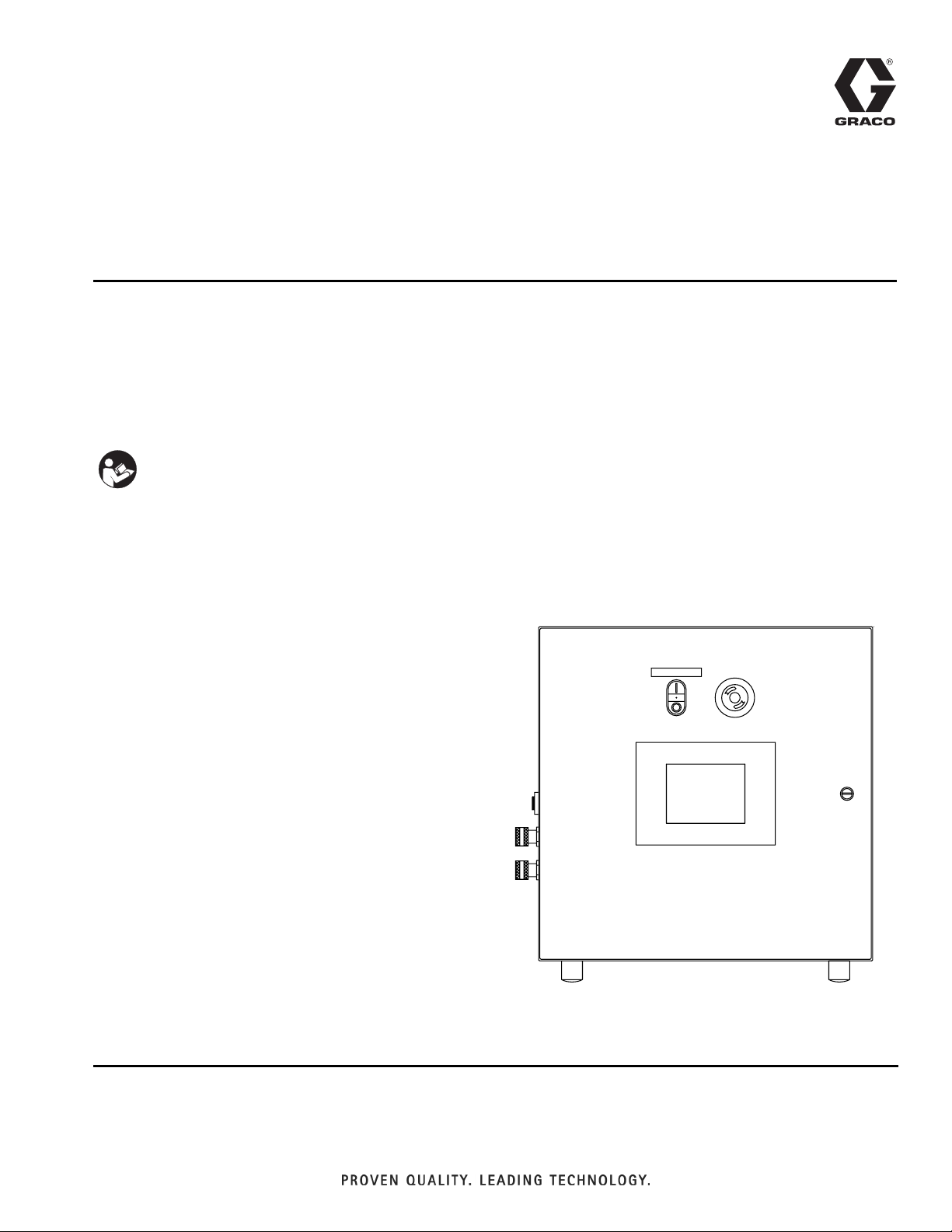
Setup - Operation
1053/1093
Control Box
Patented meter and dispense system for precise one-component micro-dispensing. Not for
use in explosive atmospheres.
Important Safety Instructions
Read all warnings and instructions in this
manual. Save these instructions.
CONTROL POWER
3A0261H
EN
Page 2

Contents
Related Manuals . . . . . . . . . . . . . . . . . . . . . . . . . . . 3
Warnings . . . . . . . . . . . . . . . . . . . . . . . . . . . . . . . . . 4
Component Identification . . . . . . . . . . . . . . . . . . . . 6
Control Boxes . . . . . . . . . . . . . . . . . . . . . . . . . . . 6
Grounding . . . . . . . . . . . . . . . . . . . . . . . . . . . . . . . . 7
Kits . . . . . . . . . . . . . . . . . . . . . . . . . . . . . . . . . . . . . . 7
Valve Connection Kits . . . . . . . . . . . . . . . . . . . . . . . 8
Setup . . . . . . . . . . . . . . . . . . . . . . . . . . . . . . . . . . . . 14
Motor Driven . . . . . . . . . . . . . . . . . . . . . . . . . . . 14
Adjust Amplifier . . . . . . . . . . . . . . . . . . . . . . . . . . . 14
Startup . . . . . . . . . . . . . . . . . . . . . . . . . . . . . . . . . . 15
Dispensing Operation . . . . . . . . . . . . . . . . . . . . . . 15
HMI Operation . . . . . . . . . . . . . . . . . . . . . . . . . . . . 16
Screen Navigation Diagrams . . . . . . . . . . . . . . 16
Main Screen . . . . . . . . . . . . . . . . . . . . . . . . . . . 17
Metering Valve Control Screen . . . . . . . . . . . . . 18
Shot Size Screen . . . . . . . . . . . . . . . . . . . . . . . 20
Level 1 Control Screen . . . . . . . . . . . . . . . . . . . 21
Level 2 Control Screen . . . . . . . . . . . . . . . . . . . 22
Purge Timer Screen . . . . . . . . . . . . . . . . . . . . . 24
Status Screen . . . . . . . . . . . . . . . . . . . . . . . . . . 26
Motor Status Screen . . . . . . . . . . . . . . . . . . . . . 27
Supervisor Screen . . . . . . . . . . . . . . . . . . . . . . 28
Supervisor Help Screen . . . . . . . . . . . . . . . . . . 30
Motor Error Codes Screen . . . . . . . . . . . . . . . . 31
Pressure Relief Procedure . . . . . . . . . . . . . . . . . . 32
Shutdown . . . . . . . . . . . . . . . . . . . . . . . . . . . . . . . . 32
Customer Inputs . . . . . . . . . . . . . . . . . . . . . . . . . . 33
Maintenance . . . . . . . . . . . . . . . . . . . . . . . . . . . . . . 34
Troubleshooting . . . . . . . . . . . . . . . . . . . . . . . . . . . 34
Schematics . . . . . . . . . . . . . . . . . . . . . . . . . . . . . . . 35
Technical Data . . . . . . . . . . . . . . . . . . . . . . . . . . . . 39
Graco Standard Warranty . . . . . . . . . . . . . . . . . . . 40
Graco Information . . . . . . . . . . . . . . . . . . . . . . . . . 40
2 3A0261H
Page 3

Related Manuals
Component manuals in U.S. English.
Part Description
313812 Dispensit 1093
313566 Dispensit 1053-10B
334001 1053 Valve 24V Solenoid Replacement Kit,
Instructions
334002 1093 Valve 24V Solenoid Replacement Kit,
Instructions
Related Manuals
3A0261H 3
Page 4
Warnings
Warnings
The following warnings are for the setup, use, grounding, maintenance, and repair of this equipment. The exclamation point symbol alerts you to a general warning and the hazard symbol refers to procedure-specific risk. Refer back
to these warnings. Additional, product-specific warnings may be found throughout the body of this manual where
applicable.
WARNING
TOXIC FLUID OR FUMES HAZARD
Toxic fluids or fumes can cause serious injury or death if splashed in the eyes or on skin, inhaled, or
swallowed.
• Read MSDS’s to know the specific hazards of the fluids you are using.
• Store hazardous fluid in approved containers, and dispose of it according to applicable guidelines.
• Always wear impervious gloves when spraying or cleaning equipment.
• If this equipment is used with isocyanate material, see additional information on isocyanates in Isocyanate Conditions Section of this manual.
PERSONAL PROTECTIVE EQUIPMENT
You must wear appropriate protective equipment when operating, servicing, or when in the operating
area of the equipment to help protect you from serious injury, including eye injury, inhalation of toxic
fumes, burns, and hearing loss. This equipment includes but is not limited to:
• Protective eyewear
• Clothing and respirator as recommended by the fluid and solvent manufacturer
•Gloves
• Hearing protection
FIRE AND EXPLOSION HAZARD
Flammable fumes, such as solvent and paint fumes, in work area can ignite or explode. To help prevent
fire and explosion:
• Use equipment only in well ventilated area.
• Eliminate all ignition sources; such as pilot lights, cigarettes, portable electric lamps, and plastic drop
cloths (potential static arc).
• Keep work area free of debris, including solvent, rags and gasoline.
• Do not plug or unplug power cords, or turn power or light switches on or off when flammable fumes
are present.
• Ground all equipment in the work area. See Grounding instructions.
• Use only grounded hoses.
• Hold gun firmly to side of grounded pail when triggering into pail.
• If there is static sparking or you feel a shock, stop operation immediately. Do not use equipment
until you identify and correct the problem.
• Keep a working fire extinguisher in the work area.
ELECTRIC SHOCK HAZARD
This equipment must be grounded. Improper grounding, setup, or usage of the system can cause electric shock.
• Turn off and disconnect power cord before servicing equipment.
• Use only grounded electrical outlets.
• Use only 3-wire extension cords.
• Ensure ground prongs are intact on power and extension cords.
• Do not expose to rain. Store indoors.
4 3A0261H
Page 5
Warnings
WARNING
PRESSURIZED EQUIPMENT HAZARD
Fluid from the gun/dispense valve, leaks, or ruptured components can splash in the eyes or on skin and
cause serious injury.
• Follow Pressure Relief Procedure in this manual, when you stop spraying and before cleaning,
checking, or servicing equipment.
• Tighten all fluid connections before operating the equipment.
• Check hoses, tubes, and couplings daily. Replace worn or damaged parts immediately.
EQUIPMENT MISUSE HAZARD
Misuse can cause death or serious injury.
• Do not operate the unit when fatigued or under the influence of drugs or alcohol.
• Do not exceed the maximum working pressure or temperature rating of the lowest rated system
component. See Technical Data in all equipment manuals.
• Do not leave the work area while equipment is energized or under pressure. Turn off all equipment
and follow the Pressure Relief Procedure in this manual when equipment is not in use.
• Check equipment daily. Repair or replace worn or damaged parts immediately with genuine manufacturer’s replacement parts only.
• Do not alter or modify equipment.
• Use equipment only for its intended purpose. Call your distributor for information.
• Route hoses and cables away from traffic areas, sharp edges, moving parts, and hot surfaces.
• Do not kink or over bend hoses or use hoses to pull equipment.
• Keep children and animals away from work area.
• Comply with all applicable safety regulations.
PLASTIC PARTS CLEANING SOLVENT HAZARD
Use only compatible water-based solvents to clean plastic structural or pressure-containing parts. Many
solvents can degrade plastic parts and cause them to fail, which could cause serious injury or property
damage. See Technica l Data in this and all other equipment instruction manuals. Read fluid and solvent
manufacturer’s warnings.
BURN HAZARD
Equipment surfaces and fluid that’s heated can become very hot during operation. To avoid severe
burns:
• Do not touch hot fluid or equipment.
3A0261H 5
Page 6
Component Identification
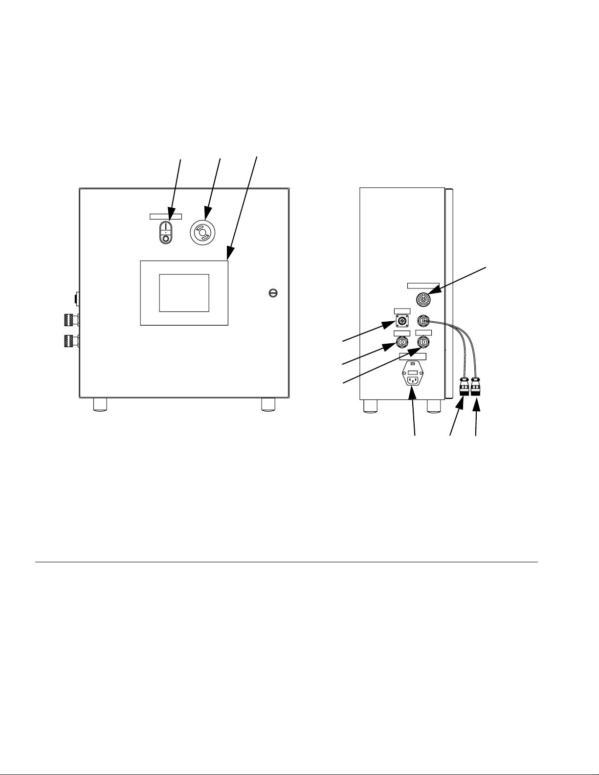
Component Identification
Control Boxes
BAC
CONTROL POWER
D
AUDIO ALARM
START OPTIONS
1
24
3
MOTOR
VALVE I/O
F
VERIFY INCOMING VOLTAGE
WITH VOLTAGE SWITCH SETTING
BEFORE CONNECTING POWER
L
U
J
E
H
Key:
A Emergency Stop
B Control Power Switch
C Touch Panel
D Alarm Speaker
E Power Input
F
IG. 1: Motor Driven Control Box
F Start Options Connection
H A Tank Level Controls Connection
J B Tank Level Controls Connection
L Dispense Valve I/O Connection
U Motor Connection
Power input/fuse holder, 81/0365-3/11, can be set to either 115V or 230V. To determine what voltage it is currently
set to, look at the port and read what is showing through the cover window. To switch voltage, open the fuse holder
cover with a small screwdriver, pull the fuse holder out, flip the fuse holder 180°, push the fuse holder back in, and
snap the fuse holder cover back into place.
NOTE: Fuse part number: V-21610P
120 V power cord part number: 81/1051-1/11
240 V power cord part number: 121054
6 3A0261H
Page 7
Grounding
Grounding
This product must be grounded. In the event of an electrical short circuit, grounding reduces the risk of electric
shock by providing an escape wire for the electric current.
Grounding plug units: this product is equipped with a
cord having a grounding wire with an appropriate
grounding plug. The plug must be plugged into an outlet
that is properly installed and grounded in accordance
with all local codes and ordinances.
Hard-wired units: the grounding wire must be used. All
electrical wiring must be done by a qualified electrician
and comply with all local codes and regulations.
Air and fluid hoses: use only electrically conductive
hoses.
Kits
NOTE: 80/2957-1/50 1053/1093 control requires three
sensor switches to operate. Valve, control, and connection kits are sold separately. Some assembly required.
Part Description
24E845★ Connection kit; for 1053 models that include
1 switch
24E846★ Connection kit; for 1053 models that include
2 switches, including the following assemblies:
A2A10007, A2A10008, A2A10009,
A2A10010, A2A10011, A2A1001,
A2A10015, A2A10016, A2A10018,
A2A10019, A2A10020, A2A10200,
A2A10300, A2A10301, A2A10302,
A2A10303, A2A10304, A2A10305,
A2A10306, A2A10307, A2A10308,
A2A10309
24E847‡ Connection kit; for 1093 models, including
the following assemblies:
A2A05401, A2A05402, A2A05403,
A2A05404, A2A05405, A2A05406
Fluid supply container: follow local code.
Solvent pails used when flushing: follow local code.
Use only conductive metal pails, placed on a grounded
surface. Do not place the pail on a non-conductive surface, such as paper or cardboard, which interrupts
grounding continuity.
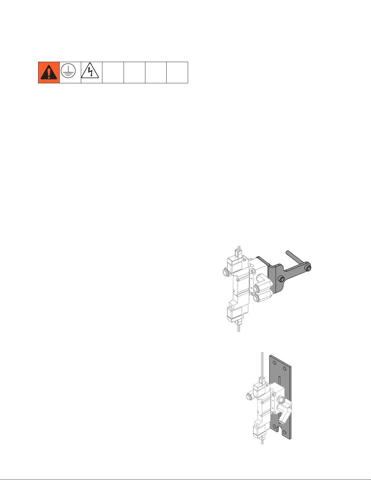
★ Mounting adapter kit 24V674 may be required for
mounting the solenoid to the 1053 valve.
‡ Mounting side plate 01/2983/97 may be required for
mounting the solenoid to the 1093 valve.
3A0261H 7
Page 8
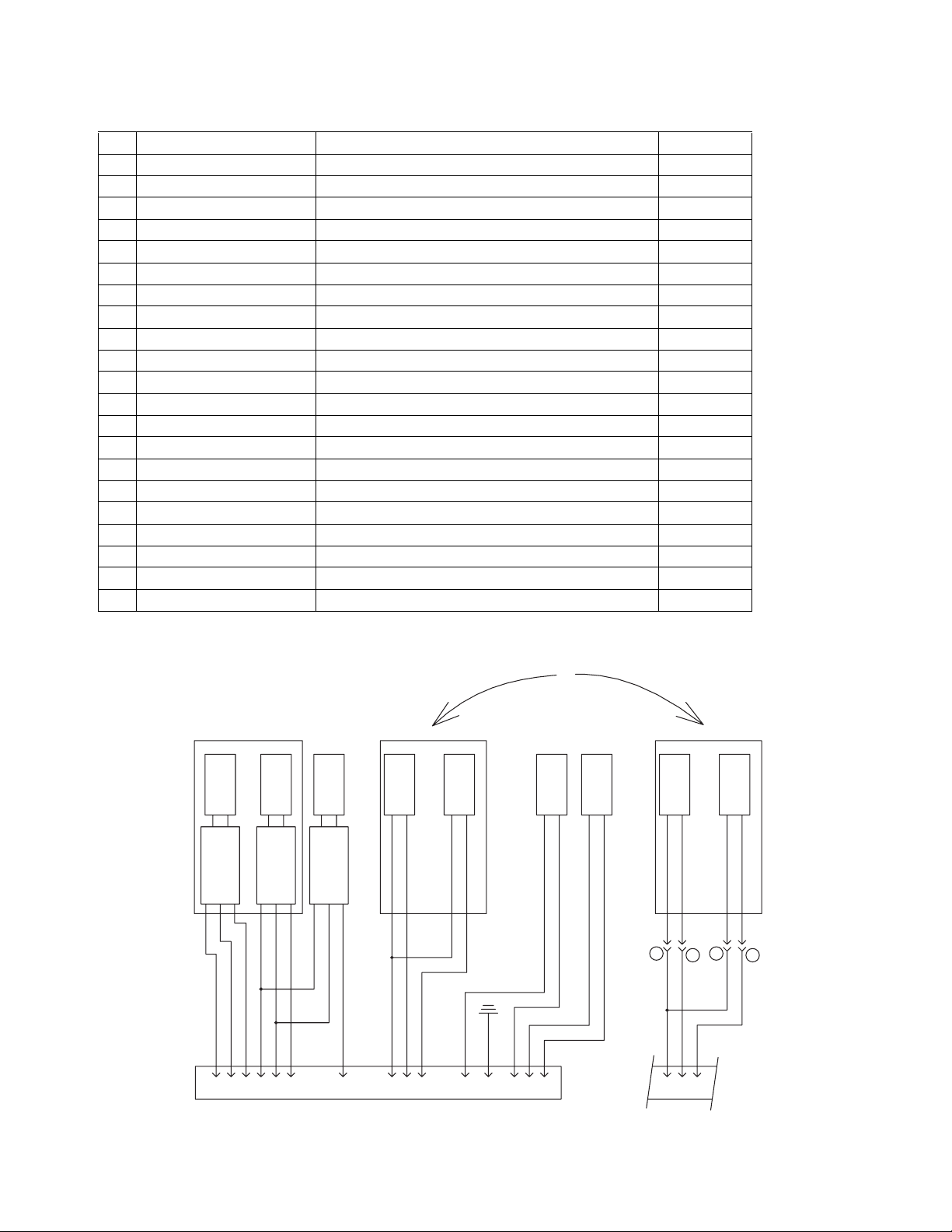
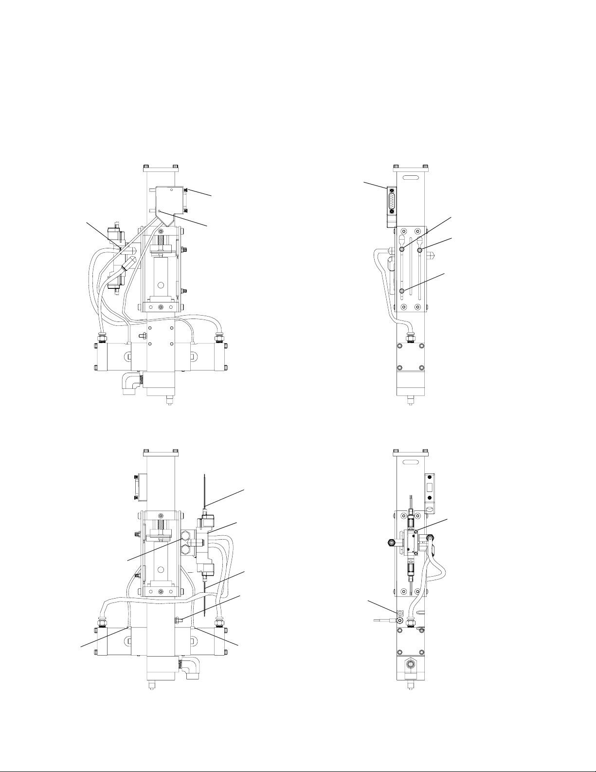
Valve Connection Kits
Valve Connection Kits
These valve connection kits enable certain valves to be used with this control package. Each kit contains the
mechanical, electrical, and pneumatic hardware needed to install the valve. See associated drawing for hardware
location and wiring information.
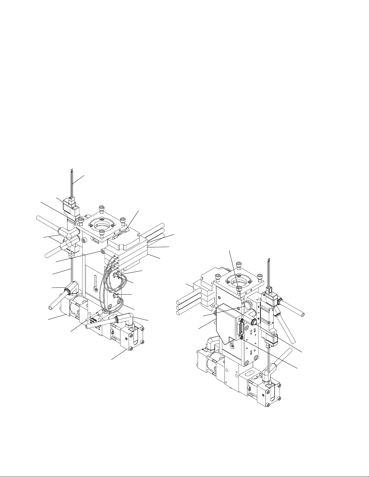
24E845, 1053 Dispense Valve with Added
Up and Down Validation/Actuation Kit
NOTE: PX-HOME must be below PX-UP. PX-HOME
may have been supplied in top hole. If so move to the
appropriate location as shown.
SOL-CSV
24
26,
28
14, 15, 16
27
SOL-OSV
23
LS-CSV
AMP-HOME
AMP-U
23
AMP-D
22
25
3,
6
PG-2
1
PX-HOME
PX-U
PX-D
17
18,
19,
20,
21
LS-OSV
2
27
4, 5
8 3A0261H
Page 9
Ref Part Description Quantity
1 96/0098/99 SCREW, socket head, 10-24x1.50 2
2 16C798 PLATE, mounting, 1053, dsub, 15 pin 1
3 ADM00022 COVER, connector, dsub, 15p, 45deg 1
4 81/0360-N/11 SCREW, jack, connector, dsub, type a 2
5 B2050001 NUT, allen, 4-40, alloy 2
6 297331 SCREW, cap, 4x1/4 2
14 81/1265/11 BRACKET, end 2
15 297639 SCREW, cap, button head 2
16 81/0283-DIN/11 RAIL, din 0.01
17 F0200075 CABLE, prox-photo 2
18 81/0378-2/25 STRAP, ground, ring, #10, 16ga 1
19 100166 NUT, full hex 1
20 96/0005-2/99 WASHER, lock, ext, #10 1
21 84/0130-25/11 LABEL, prot earth(grnd).375x.375 1
22 16D050 AMPLIFIER, 1chan, photo, pnp, 24vdc 2
23 94/0740-A/99 FITTING, elbow, swivel, 1/4tubex10-32 2
24 127629 VALVE, solenoid, 4 way, 3 position, 24V 1
25 82/0217-A/11 MUFFLER, air, 1/8 NPT 2
26 127632 SCREW, socket head, 4-40x1.00 2
27 94/0705-1/96 FITTING, elbow, swivel, 1/4 tube 3
28 17A412 WASHER, split, #4 2
Valve Connection Kits
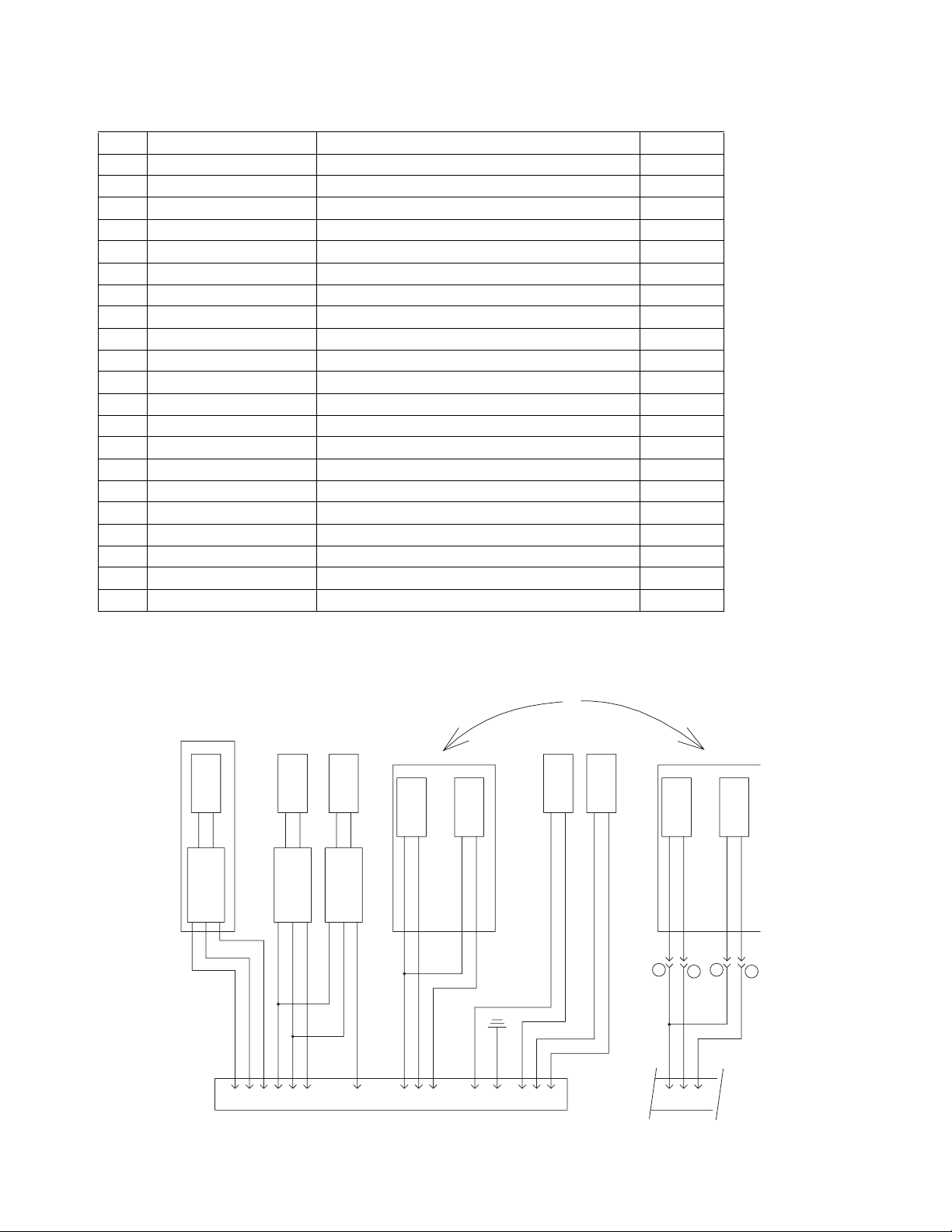
24E845 Electrical socket schematic
%/.
%/8
3;8
$038
,1&/8'(':,7+%$6(9$/9(
+22.83)25)6:,7&+
%51
%/.
3;+
$03+
,1&/8'(':,7+%$6(9$/9(
%51
%/8
%/.
%/8
%51
3;'
$03'
/6&69
:+,7(
%52:1
:+7
%51
:+7
/6269
:+,7(
%52:1
5('
*51
%/.
5('
62/&69
%/$&.
5('
%/.
25
5('
62/269
/6&69
+22.83)2586:,7&+
,1&/8'(':,7+%$6(9$/9(
%/$&.
%51
%/8
%/8
%51
WLDB(H
/6269
%/8
&211(&7,21729$/9(&21752/6
3,1'68%&211(&7253*
3A0261H 9
Page 10
Valve Connection Kits
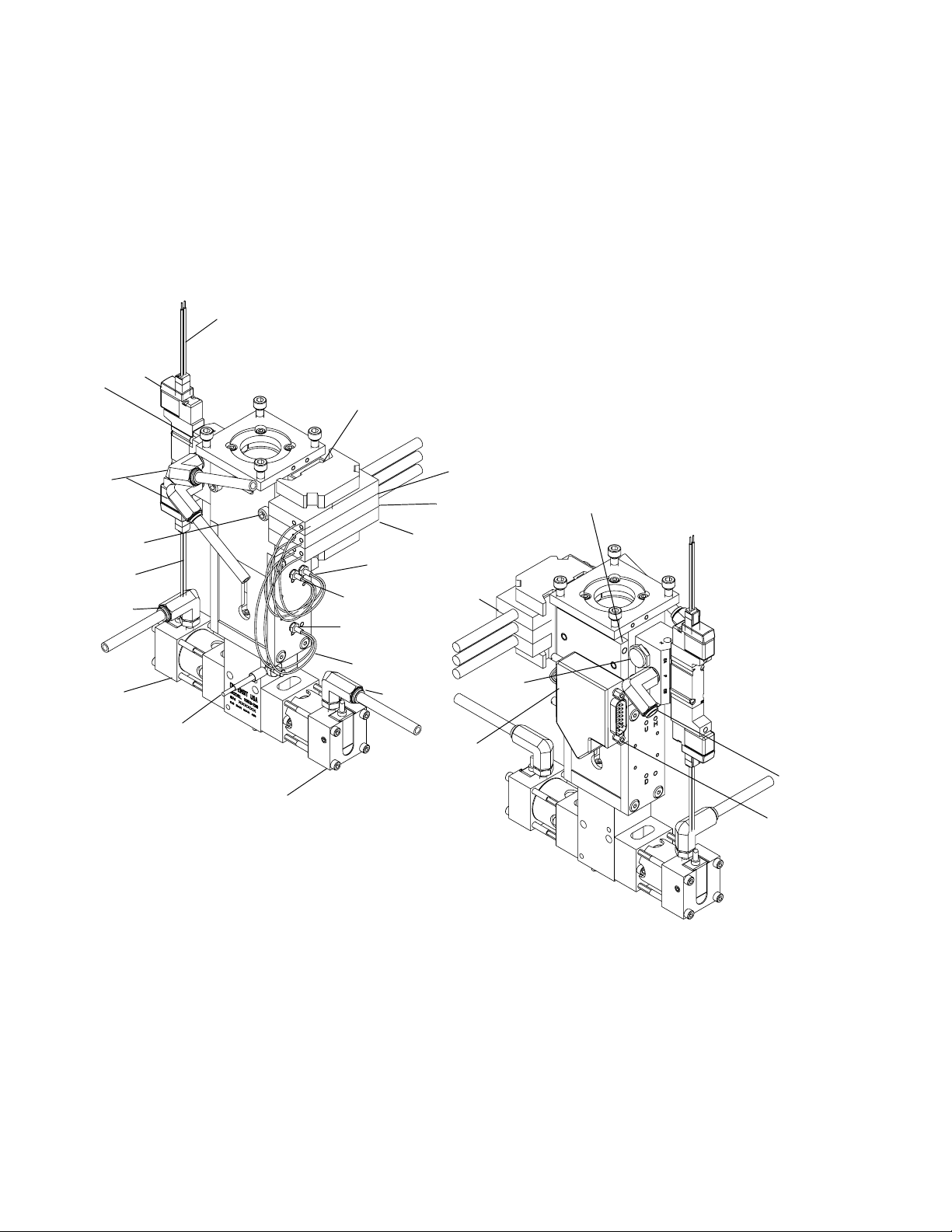
24E846, 1053 Dispense Valve with Added
Up Validation/Actuation Kit
NOTE: PX-HOME must be below PX-UP. PX-HOME
may have been supplied in top hole. If so move to the
appropriate location as shown.
SOL-CSV
24
26,
28
14, 15, 16
27
SOL-OSV
23
LS-CSV
AMP-HOME
AMP-U
23
AMP-D
22
25
3,
6
PG-2
1
PX-HOME
PX-U
PX-D
17
18,
19,
20,
21
LS-OSV
2
27
4, 5
10 3A0261H
Page 11
Ref Part Description Quantity
1 96/0098/99 SCREW, socket head, 10-24x1.50 2
2 16C798 PLATE, mounting, 1053, dsub, 15 pin 1
3 ADM00022 COVER, connector, dsub, 15p, 45deg 1
4 81/0360-N/11 SCREW, jack, connector, dsub, type a 2
5 B2050001 NUT, allen, 4-40, alloy 2
6 297331 SCREW, cap, 4x1/4 2
14 81/1265/11 BRACKET, end 2
15 297639 SCREW, cap, button head 2
16 81/0283-DIN/11 RAIL, din 0.01
17 F0200075 CABLE, prox-photo 1
18 81/0378-2/25 STRAP, ground, ring, #10, 16ga 1
19 100166 NUT, full hex 1
20 96/0005-2/99 WASHER, lock, ext, #10 1
21 84/0130-25/11 LABEL, prot earth(grnd).375x.375 1
22 16D050 AMPLIFIER, 1chan, photo, pnp, 24vdc 1
23 94/0740-A/99 FITTING, elbow, swivel, 1/4tubex10-32 2
24 127629 VALVE, solenoid, 4 way, 3 position, 24V 1
25 82/0217-A/11 MUFFLER, air, 1/8 NPT 2
26 127632 SCREW, socket head, 4-40x1.00 2
27 94/0705-1/96 FITTING, elbow, swivel, 1/4 tube 3
28 17A412 WASHER, split, #4 2
Valve Connection Kits
24E846 Electrical socket schematic
%/8
3;8
$038
+22.83)25)6:,7&+
,1&/8'(':,7+%$6(9$/9(
%52:1
%51
%/.
%51
%/.
%/8
3;'
$03'
%/.
%51
3;+
$03+
,1&/8'(':,7+%$6(9$/9(
%/8
%51
/6&69
:+,7(
:+7
:+7
/6269
:+,7(
%52:1
5('
*51
%/.
5('
5('
%/.
25
62/&69
%/$&.
5('
62/269
%/$&.
/6&69
+22.83)2586:,7&+
,1&/8'(':,7+%$6(9$/9(
%/8
%51
%/8
%51
/6269
%/8
WLDB(H
&211(&7,21729$/9(&21752/6
3,1'68%&211(&7253*
3A0261H 11
Page 12
Valve Connection Kits
24E847, 1093 Dispense Valve with Added
Actuation Kit
NOTE: PX-HOME must be below PX-UP. PX-HOME
may have been supplied in top hole. If so move to the
appropriate location as shown.
4, 5
3
PG-2
27
PX-UP
6
PX-HOME
PX-DOWN
SOL-CSV
24
25
LS-CSV
12 3A0261H
SOL-OSV
18, 19, 20
LS-OSV
21
26, 28
Page 13

Ref Part Description Quantity
3 ADM00022 COVER, connector, dsub, 15p, 45deg 1
4 81/0360-N/11 SCREW, jack, connector, dsub, type a 2
5 B2050001 NUT, allen, 4-40, alloy 2
6 297331 SCREW, cap, 4x1/4 2
18 81/0378-2/25 STRAP, ground, ring, #10, 16ga 1
19 100166 NUT, full hex 1
20 96/0005-2/99 WASHER, lock, ext, #10 1
21 84/0130-25/11 LABEL, prot earth(grnd).375x.375 1
24 127629 VALVE, solenoid, 4 way, 3 position, 24V 1
25 82/0217-A/11 MUFFLER, air, 1/8 NPT 2
26 127632 SCREW, socket head, 4-40x1.00 2
27 94/0705-1/96 FITTING, elbow, swivel, 1/4 tube 3
28 17A412 WASHER, split, #4 2
24E847 Electrical socket schematic
Valve Connection Kits
%/.
%/8
3;'
%51
%/.
3;+
,1&/8'(':,7+%$6(9$/9(
%/8
%51
&211(&7,21729$/9(&21752/6
3,1'68%&211(&7253*
%/8
3;8
%51
%/.
/6&69
%51
%/.
%/8
/6269
%51
5('
%/.
62/&69
%/$&.
5('
%/.
5('
%/.
*51
62/269
5('
%/$&.
WLDB(H
3A0261H 13
Page 14

Setup
Setup
Motor Driven
1. Connect Dispense Valve I/O, Start Options, and
Motor logic cables. If level controls are installed,
connect Level Controls logic cables.
NOTICE
Feed system and main logic control system must
use separate air supplies.
AUDIO ALARM
START OPTIONS
1
24
3
MOTOR
VALVE I/O
VERIFY INCOMING VOLTAGE
WITH VOLTAGE SWITCH SETTING
BEFORE CONNECTING POWER
Adjust Amplifier
The amplifier should be adjusted if:
• Debris or vibration changed the distance/axis
between the sensor and metering block (13).
• Replacing the sensor.
1. Navigate to the Motor Status screen.
2. Ensure the metering rod connection block (13) is
aligned with the sensor.
3. If the display shows a “0” for the sensor switch being
adjusted, increase the amplifier intensity adjustment
screw until the sensor switch display changes to “1”.
4. Repeat for each sensor switch installed on assembly.
2. Adjust customer supplied air pressure regulator to
80 psi (0.6 MPa, 6 bar).
3. Perform Setup procedure for dispense valve and
feed system components. See Related Manuals on
page 3.
14 3A0261H
Page 15

Startup
Startup
NOTE: See HMI Operation starting on page 16 for
detailed HMI instructions.
1. Press the Control Power On button.
2. Navigate to the Metering Valve Control screen.
3. Press the Retract button.
NOTE: On Motor Driven models, when there is an
Emergency Stop condition or the system power is lost,
the shot selection resets to “0”. The operator must then
select a shot.
4. Navigate to the Supervisor screen.
5. Press the Valve Type selection button to select your
configuration.
6. Navigate to the Shot Size screen.
7. Select a shot number.
8. Navigate to the Metering Valve Control screen.
Dispensing Operation
NOTE: See HMI Operation on page 16 for detailed HMI
instructions.
The foot switch, the “Start” button, and the optional Customer Start Signal can be used to initiate shots. These
are referred to as start devices.
Perform a Shot
1. Navigate to the Metering Valve Control screen.
2. Press the Retract button.
3. Press the Shot button to select Shot Mode.
4. Press and release the start device to perform one
shot.
Dispense Continuously
The valve dispenses continuously until the end of the
stroke is reached.
9. Press the Shot button to select Shot Mode.
10. Verify air pressure is set to 80 psi (5.6 bar).
11. Perform feed system startup procedure(s). See
Related Manuals on page 3.
12. Perform dispense valve startup procedure. See
Related Manuals on page 3.
1. Navigate to the Metering Valve Control screen.
2. Under Metering Valve Control, press the Retract
button.
3. Press the Continuous button.
4. On Motor Driven models, press and hold the start
device to dispense continuously. Release the start
device to stop dispensing and retract the metering
rods.
Retract Piston
1. Navigate to the Metering Valve Control screen.
2. Under Metering Valve Control, press the Retract
button.
Extend Piston
1. Navigate to the Metering Valve Control screen.
2. Under Metering Valve Control, press the Extend button.
3A0261H 15
Page 16

HMI Operation
HMI Operation
Screen Navigation Diagrams
Motor Driven
Main Screen
Metering Valve Control
Shot Size/Flow Rate
FIG. 2
Level 1 Control
Purge Timer
Status
Supervisor Supervisor Help
Motor Status Motor Error Codes
Level 2 Control
16 3A0261H
Page 17

Main Screen
NOTE: The Error Code button is shown on every screen
on the Motor Driven model.
HMI Operation
Screen Access Buttons
All buttons on the main screen except for the Password
and Error Code buttons open a new specified screen.
For example, pressing the “Status” button opens the
Status screen.
Password
The password button enables the user to changes
values in certain screens.
To access the password press the Password Access
button (shown as “=0000”). When the keyboard appears
enter “5810”
Error Code
NOTE: The Error Code button is shown on every screen
On all screens that it is shown, the Error Code button
resets the error seen in the error string (shown as
“<0000000000”) and the error code number (shown as
“<000”). See the Motor Error Codes screen for more
information, page 31.
then press the Enter key.
3A0261H 17
Page 18

HMI Operation
Metering Valve Control Screen
NOTE: A “1” indicates that the button is in the “ON” posi-
tion. A “0” indicates that the button is in the “OFF” position.
NOTE: The Error Code button is shown on every
screen. See the Main screen for definition.
Start button
When the Start button is pressed, the machine starts
the cycle for the selected Pump Mode.
Pump Mode
NOTE: The metering rods must be retracted prior to
changing any setting under Pump Mode. See Retract
Piston, page 15.
Retract Mode
The air cylinder and pumps immediately retract and
remain in the retracted position. This is used for maintenance purposes only.
Extend Mode
The air cylinder and pumps immediately extend and
remain in the extended position. This position must be
selected when the pump is idle for a long period of time.
Shot Mode
The machine cycles the number of times displayed in
the Cycle Counter field when the start device is pressed
and released. The machine cycles continuously when
the start device is pressed and held.
Continuous (Operator Control) Mode
In this mode, the machine to dispense while the start
device is pressed. When the start device is released the
metering rods retract to the home position.
18 3A0261H
Page 19

DV Valve Mode
This mode actuates an optional dispense valve.
OPEN
In this mode, the dispense valve is held in the open position, allowing material to pass through.
AUTO
In this mode, the dispense valve opens automatically
whenever the pump is cycled.
CLOSE
In this mode, the dispense valve is held closed.
HMI Operation
3A0261H 19
Page 20

HMI Operation
Shot Size Screen
NOTICE
Erratic operation results if the shot size value entered is
not greater than the absolute value of the Shot Size Offset setting. For example, if the Shot Size Offset setting
is -1%, a shot size greater than 1% must be entered.
See Supervisor screen, page 28.
Select Shot Size/Flow Rate Combination
Use this to change the selected shot by entering a number between 1 and 7. The selected shot size and flow
rate is shown in the Shot Size (percent) section and
Flow Rate (mm/sec) section.
Number of Strokes
This displays the number of shots of material when the
machine is dispensing.
For example, if the purge shot size is set at 150%, Number of Strokes displays a “2”, and the Amount Per
Stroke % displays “75.00”.
Amount Per Stroke %
Shot Size (percent), Flow Rate (mm/sec)
These are the 7 preset Shot Size (percent) and Flow
Rate (mm/sec) values. Shot size is in percent of stroke.
The preset values can be selected using Select Shot
Size/Flow Rate Combination.
To edit the preset Shot Size or Flow Rate values, log-in
as the supervisor. See Main Screen, page 17.
Below is the minimum and maximum field allowance for
this design.
Shot Size:
Minimum = 2.5%
Maximum = 500.0%
Flow Rate:
Minimum = 0.50 mm/second
Maximum = 25.00 mm/second
This displays the stroke per shot in percent of stroke.
For example, if the purge shot size is set at 340%,
Amount Per Stroke % displays “85.00” and Number of
Strokes During Purge displays a “4”.
20 3A0261H
Page 21

Level 1 Control Screen
NOTE: The Error Code button is shown on every
screen. See the Main screen for definition, page 17.
NOTE: If ‘A Tank Status’ and ‘B Tank Status’ both display 'Levels Not Active' then the level control feature is
not installed on this machine.
HMI Operation
A Tank Status, B Tank Status
This displays information about each component tank
filling process. The following are the possible messages.
Message Description
Material
High
Material
Low
Filling The tank is currently refilling in the tank refilling
Material
Present
Level Sensor Fault
Levels Not
Active
Fill Fault The tank began refilling and the fluid level did not
The tank level is at or above the high level sensor.
The tank level is below the low level sensor.
process.
The tank level is between the high and the low
level sensors.
The machine senses material at the high level
sensor but not at the low level sensor.
Level sensors are not installed for the tank.
reach the high level sensor within the preset time
entered into the Fill Timer button seen in the
Level2 Control screen. Tank has stopped refilling.
Silence Alarm button
Start Fill A, Start Fill B button
When this button is pressed the transfer pump fills the
tank until the material level reaches the high level sensor on that tank.
NOTE: The Start Fill A, Start Fill B and the Stop Fill buttons are inoperable if the high level automatic tank refilling feature was not purchased with this machine.
Stop Fill button
This button stops the automatic tank refilling process for
both the A and B component material tanks.
This button silences the audible alarm when pressed.
3A0261H 21
Page 22

HMI Operation
Level 2 Control Screen
NOTE: A “1” indicates that the button is in the “ON” posi-
tion. A “0” indicates that the button is in the “OFF” position.
NOTE: The Error Code button is shown on every screen
on the Motor Driven PD44. See the Main screen for definition, page 17.
NOTE: In the Level 1 Control Screen, if ‘A Tank Status’
and ‘B Tank Status’ both display 'Levels Not Active' then
the level control feature is not installed on this machine.
Press the Main button to exit from this screen.
Low Level Shutdown button
When this button displays ‘1’ and the material level of
either the ‘A’ component tank or the ‘B’ component tank
goes below the low level sensor, the machine shuts
down. To recover, refill the component tank with material
to above the low level sensor. When ‘0’ is displayed, the
low level shutdown feature is disabled.
Alarm Engage button
When this button displays ‘1’ and the material level of
either the ‘A’ component tank or the ‘B’ component tank
goes below the low level sensor the audible alarm is
activated.
Auto Fill Engage button
When this button displays ‘1’ the automatic filling function is activated.
Clear Fill Fault button
This button clears the Fill Timer Fault message displayed in the corresponding ‘A Tank Status’ or ‘B Tank
Status’ field in the Level 1 Control screen.
Silence Alarm button
Press this button to silence the low fluid level audible
alarm. The audible alarm will be activated again when
the low level condition reoccurs.
22 3A0261H
Page 23

HMI Operation
Shutdown Timer button/indicator
NOTE: If the level control option has not been pur-
chased the Shutdown Timer button is disabled.
This changes the delay before the Fill Timer Fault message is displayed in the corresponding ‘A Tank Status’ or
‘B Tank Status’ field on the Level 1 Control screen. If the
material level is below the low level sensor for more than
the duration of the Shutdown Timer setting, the machine
shuts down.
To change the Shutdown Timer setting, perform the following steps.
1. Select the Shutdown Timer button (shown as
“=00000”). A numeric keypad appears.
2. Enter the desired Shutdown Timer setting in tenths
of a second.
NOTE: For example, if 15 is entered, the shutdown time
is 1.5 seconds.
3. Press the button. The new Shutdown Timer setting is shown.
NOTE: For example, if 15 is entered, the Fill Timer setting is 1.5 seconds.
3. Press the button. The new Fill Timer setting
appears in the Fill Timer field.
NOTE: The current Fill Timer time is shown by
“<00000”. This counts up to the preset time.
NOTE: The current time of the Shutdown Timer is
shown by “<00000”. This counts up to the preset time.
Fill Timer
NOTE: If the automatic refilling option has not been pur-
chased the Fill Timer function is disabled.
This changes the delay before the Fill Timer Fault message is displayed to the corresponding ‘A Tank Status’
or ‘B Tank Status’ field in the Level 1 Control screen. If
the material level reaches the tank high level sensor
before the preset fill time elapses, the ‘Tank High Level’
message is displayed in the Tank Status field and the Fill
Timer is reset. If the preset fill time expires before material reaches the high level sensor, “Fill Timer Fault”
appears in the Level1 Control Screen.
To change the Fill Timer setting, perform the following
steps.
1. Select the Fill Timer button (shown as “=00000”). A
numeric keypad appears.
2. Enter in the Fill Timer time in tenths of a second.
3A0261H 23
Page 24

HMI Operation
Purge Timer Screen
NOTE: The Error Code button is shown on every
screen. See the Main screen for definition, page 17.
Purge Timer On /Off
Always set the dwell/alarm timer to a value that will
give the user adequate warning that the machine is
about to dispense a purge shot.See Dwell / Alarm
Timer section on page 25.
The Purge Timer On/Off switch is used to enable/disable the Purge Timer.
OFF: The Purge Timer is disabled.
ON: The Purge Timer is enabled. The machine initiates
a purge shot when the purge timer expires provided the
fluid ball valves are open, Shot Mode is selected, and no
errors exist.
Enter Purge Time Button
The Enter Purge Time button is shown as “=000.0”
below the Purge Timer On /Off button. The Enter Purge
Time button allows the operator to set the required time
between cycles. When the Purge Timer switch is in the
ON position and the Pump Mode switch is in the Shot or
Operator Control position, the purge timer unit counts up
to the preset time. When it reaches the preset time, a
purge shot is initiated.
The timer then automatically resets and continues with
the sequence of cycling and resetting. It continues until
the Purge Timer is turned to the OFF position.
To change the Purge Timer setting, perform the following steps.
1. Select Purge Timer button. A numeric keypad
appears.
2. Enter the desired purge time in seconds. Use the “.”
button to enter tenths of a second.
3. Press the button. The Purge Timer screen
appears. The new purge time appears in the Purge
Timer button.
24 3A0261H
Page 25

HMI Operation
NOTE: The current Purge Timer time is shown in the
bottom text box below the Purge Timer button.
Calculating the Purge Timer Setting
If the shot size is larger than the mixer volume, set the
timer for one-half the gel time of the material. If the shot
size is smaller, use the following formula to determine
the Purge Timer setting.
Gel Time X Shot Size
= Timer Setting
2 X Mixer Volume
For example, with mixer volume = 13.3cc, shot size =
10cc, gel time = 10 minutes, use the following equation.
10 min X 10 cc
100 cc*min
= 3.76 min=
2 X 13.3 cc
26.6 cc
Dwell / Alarm Timer
Always set the dwell/alarm timer to a value that will
give the user adequate warning that the machine is
about to dispense a purge shot.
1. Select Purge Shot Size % button. A numeric keypad
appears.
2. Enter the desired material shot size volume.
3. Press the button. The Purge Timer screen
appears. The new shot size percentage appears in
the Purge Shot Size % field.
Number of Strokes During Purge button/indicator
This displays the number of strokes used during the
purge shot.
For example, if the purge shot size is set at 150%, Number of Strokes During Purge displays “2” and Amount
Per Stroke % displays “75”.
Amount Per Stroke %
This displays the percent of the stroke used during a
shot.
For example, if the shot size is set at 150%, Number of
Strokes During Purge displays “2” and Amount Per
Stroke % displays “75”.
This changes the duration that the audible alarm is
active prior to the purge shot being initiated.
To change the Dwell Timer, perform the following steps.
1. Select the Dwell Timer button. A numeric keypad
appears.
2. Enter the desired Dwell Timer time in seconds. Use
the “.” button to enter tenths of seconds.
3. Press the button. The new Dwell Timer time
appears in the Dwell Timer field.
NOTE: The current Dwell Timer time is shown by
<000.0.
Purge Shot Size % button
This button shows the Shot Size volume in percent of
stroke. This volume is dispensed during the ratio check.
To change the Purge Shot Size % volume, perform the
following steps.
3A0261H 25
Page 26

HMI Operation
Status Screen
NOTE: A “1” indicates that the button is in the “ON” posi-
tion. A “0” indicates that the button is in the “OFF” position.
NOTE: The Error Code button is shown on every
screen. See the Main screen for definition, page 17.
Maintenance Totalizer
This counter increments each time the machine cycles.
Press the Reset Maintenance Totalizer button to reset.
This counter is used for maintenance purposes.
# Of Times Maintenance Totalizer has been Reset
This counter increments each time the Reset Maintenance Totalizer button is pressed.
Reset Maintenance Totalizer button
This button resets the Maintenance Totalizer.
Cycle Totalizer
This counter increments each time the machine cycles.
Dispense Ready
This displays “1” if the metering rods are loaded with
material and ready to dispense. It displays a “0” if the
metering tube is reloading or at the end of the dispense
cycle.
Dispense Complete
This displays “1” if the metering rods are reloaded with
material or at the end of the dispense cycle, and displays a “0” if the metering tube is loaded with material
and ready to dispense.
Contrast + button
This button increases the contrast of the screen.
Contrast - button
This button decreases the contrast of the screen.
PLC=XXXX, HMI=XXXX
These fields display the programs downloaded into the
PLC and HMI.
26 3A0261H
Page 27

Motor Status Screen
HMI Operation
NOTE: A “1” indicates that the button is in the “ON” position. A “0” indicates that the button is in the “OFF” position.
NOTE: The Error Code button is shown on every
screen. See the Main screen for definition, page 17.
To navigate to the Motor Status screen, press the “Motor
Status” button on the Status screen.
CSV Switch (Closed Spool Valve Switch)
This displays “1” when the spool valve is in the closed or
reload position.
OSV Switch (Open Spool Valve Switch)
This displays “1” when the spool valve is in the open or
dispense position.
Home Switch (Home Limit Switch)
This displays “1” when the metering valve rod home
switch is activated.
Upper Switch (Upper Over Limit Switch, Extend)
This displays “1” when the metering valve rod upper
over-travel limit switch is activated. The dispense valve
is in the most-retracted position.
Lower Switch (Lower Over Limit Switch, Retract)
This displays “1” when the metering valve rod lower
over-travel limit switch is activated. The dispense valve
is in the most-extended position. Put the dispense valve
in this position when it is idle for a long period of time.
Motor Position (Steps)
This gives the motor step position in terms of transducer
steps.
Shot Size %
This shows the Shot Size volume in percent of stroke.
Flow Rate (mm/sec)
This allows the operator to view the current flow rate in
millimeters per second.
Shot Mode Step #
This gives the current step in the shot mode program.
This is used for troubleshooting.
Reload Mode Step #
This gives the current step in the reload mode program.
This is used for troubleshooting.
Oper. Mode Step #
This gives the current step in the operator mode program. This is used for troubleshooting.
3A0261H 27
Page 28

HMI Operation
Supervisor Screen
NOTE: A “1” indicates that the button is in the “ON” posi-
tion. A “0” indicates that the button is in the “OFF” position.
NOTE: To change the values on this screen, log-in as
the supervisor. See Main Screen, page 17.
Error Code button
This button resets the error in the error string (shown as
“<0000000000”) and the error code number (shown as
“<000”). See the Motor Error Code screen for more
information, page 31.
Reload Setup
Only one of the three Reload Setup Options can be
enabled at any given time.
Reload After Each Shot button
In this mode, the metering rods retract after every shot.
This is the default system setup.
Reload After Multiple Shots button
In this mode, the metering rods retract only when the
metering rods are about to reach the end of the stroke.
This feature is only available when in Operator Control
mode.
For example, if the selected shot size is 30% of the
metering rods stroke, three shots will be taken (90% of
the stroke) then the metering rods will retract. The rods
retract after three shots because it cannot do another
shot without going over 100% stroke. If the selected shot
size is greater than 50% of the metering rods stroke, the
metering rods will retract after every shot.
Manual Reload W/ Customer Signal button
In this mode, the customer must send a signal to reload
the valve before the lower switch is activated. Otherwise,
the dispense valve will initiate a shot using the selected
shot size and flow rate combination.
NOTE: This can be linked with a PLC input for system
integration. See the logic drawings for more information.
Reload Speed (mm/sec) button
This allows the operator to change the retract or reload
speed in millimeters per second.
Feed Setup
This allows the operator to choose the low level setting
for the feed system with tanks or a feed system with cartridge or syringes. This inverts the switch function in the
PLC logic.
28 3A0261H
Page 29

Valve Type
Only one of the three valve type options can be enabled
at any given time. This feature is enabled at the time of
build based on Valve Type and should not be manipulated.
Enabling the Valve Type with a 1053 - 1 in. when a 1053
- 2 in. or 1093 is used will cause the improper maximum
shot size allowed by the mechanics of the valve.
Enabling the Valve Type with the 1053 - 2 in. when a
1053 - 1 in. will cause the Low Switch to be tripped and
will not allow the Valve to cycle.
Enabling the Valve Type with the 1053 - 2 in. when a
1093 is used will cause the improper maximum shot size
allowed by the mechanics of the valve.
Enabling the Valve Type with the 1093 when a 1053 - 1
in. or 1043 - 2 in. is used will cause the Low Switch or
PF44 to be tripped and will not allow the Valve to cycle.
HMI Operation
3A0261H 29
Page 30

HMI Operation
Supervisor Help Screen
This screen describes the various reload and shot
options in the Supervisor screen.
To get to the Setup Help screen, press the “Help” button
on the Supervisor screen.
30 3A0261H
Page 31

Motor Error Codes Screen
These screens give descriptions of the motor error
codes.
HMI Operation
3A0261H 31
Page 32

Pressure Relief Procedure
Pressure Relief
Procedure
1. Turn main air supply shut-off/bleed valve to the off
position. This will bleed air from the system.
2. Perform feed system pressure relief procedure. See
Related Manuals on page 3.
3. Perform dispense valve pressure relief procedure.
See Related Manuals on page 3.
Shutdown
1. Go to the Metering Valve Control screen.
2. Press the Retract button.
3. Press the Extend button.
4. Press the Emergency Stop button. Ensure everything is off.
5. Twist Emergency Stop to reset.
6. Perform Pressure Relief Procedure.
7. Perform feed system shutdown procedure. See
Related Manuals on page 3.
8. Perform dispense valve shutdown procedure. See
Related Manuals on page 3.
32 3A0261H
Page 33

Customer Inputs
Customer Inputs
Name Description
Customer Start (Input) When a momentary contact closure is applied to this input, the start device is
activated.
Customer Purge Start
(Input)
Customer SS/FR Bit 1,2,3
(Input)
Customer Signal Done
(Output)
Customer Signal Dispense Ready (Output)
Customer Signal Time to
Purge (Output)
Customer Signal Open
Auxiliary Dispense Valve
(Output)
Customer Signal Reload
(Input)
When a momentary contact closure is applied to this input, the purge shot is
activated.
When these inputs are activated in the proper sequence, the machine activates the Shot Size and Flow Rate Combination seen on the Shot Sizes
screen. See the machine logic drawings for more information.
This output activates for 2 seconds after the dispense cycle is complete.
This output is active when the machine is in the Shot Mode and the dispense
valve is retracted and loaded with material. This output deactivates when the
dispense valve is dispensing or if the machine is not in the shot mode.
If the Manual Reload W/ Customer Signal button under the Supervisor screen
is selected, this output is active when it is time for the machine to take a purge
shot.
NOTE: The dispense valve will not perform a purge shot until the start device
is activated.
This is to be used only when there is a metering valve feeding an on/off type
dispense valve. This signal is used to open and close the dispense valve.
When in customer reload mode, after each shot the dispense “Done” signal is
turned on for 2 seconds. During this time the customer can toggle the customer reload signal to reload the system. If the timer expires, the machines
assumes the customer does not want to reload and finishes the sequence
then turns on the ready signal and does not allow another reload until after the
next shot.
3A0261H 33
Page 34

Maintenance
Maintenance
NOTE: If material is leaking, see Troubleshooting on
page 34.
See Related Manuals on page 3 for dispense valve and
feed system maintenance socket schedule and procedures.
Air-Water Separator/Filter
Drain water once a shift or as necessary.
Troubleshooting
Perform Pressure Relief Procedure before performing any troubleshooting procedure.
Problem Cause Solution
Dispense valve stalling and no material being dispensed despite adequate input pressure
Dispense valve not discharging normal or full volume
Material leaks past spool valves Spool valve worn or damaged Replace the spool valve and sleeve
Material leaks around needle while
dispensing
The horn beeps after each shot Dispense is longer than the dispense
The horn beeps continuously If the low level sensors are on, the
Blocked needle Check needle for cured material,
replace mixer as required
Flow control valve closed Open
Low material level in reservoirs Fill material reservoirs and prime the
machine
Air in material tanks Fill reservoirs and prime machine
Cured material in needle Check mixer for cured material,
replace needle
Check mixer for cured material
limit timer
Check level screen for low level con-
system may be low on material
dition, if low level condition is present,
fill tank with material
34 3A0261H
Page 35

Schematics
Schematics
78
ON ON
CLOSEST TO DRIVE MOUNTING FACE
SW-2 LOCATED UNDER DRIVE HOUSING
CLOSEST TO DRIVE FACE
SW-1 LOCATED UNDER DRIVE HOUSING
OFF ON
3456
OFF ON
1 2
ON OFF
ON
OFF
8
ON
654 7
OFF
ON OFF
OFF
ON
23
ON
1
OFF
ON
OFF
M1
RED
50% REDUCTION
SERIES
5000
WIRING CONFIG:
RESOLUTION:
ENABLED
-4% 3rd HARMONIC
WAVE FORM:
ANTI-RESONANCE:
AUTO STANDBY:
8
ORANGE
BROWN
9
S57-102-MO
PG-5
MOTOR:
BLUE
RED
BARE
GREEN
BLACK
YELLOW
1
7
3
5
624
RED
BARE
GREEN
BLACK
WHITE WHITE
GREEN
2.60 AMPS
<32mH
LEDS
AC POWER APPLIED
NO AC POWER SUPPLIED
FAULT CONDITION
* DRIVE OVERTEMPERATURE
GAIN:
CURRENT:
LED COLOR:
OFF
RED
GREEN
* SHORT CIRCUIT
OFF
ON
NOTE: SET DIP SWITCHES BEFORE WIRING DRIVE
ONONOFF
21
23
22
20
16
E-AC
PARKER
GND
N
L1
MOTOR DRIVE
PINOUT
LOOKING
AT DRIVE
1714151918
1
5
3
2
6
4
24
9
8
7
11
101213
PG-DRIVE
25
CN-4
B+B-A+A-GND
-
-
3
46-5-
22
LMT-
-
FAULT + (C)
8-
7
MODULE
EM-253
POSITION
M
+5V
STEP -14
RESET +
DIRECTION -
SHUTDOWN +
12 -
11-9
10
25
M
P0-
16
15
13 -
272826
25
ORG
WHITE
BLUE
21
P1+
P1-
PO+
FAULT - (E)
SHUTDOWN -
17
18 -
RESET -23
24 -
22 -2021-19 -
25-
NOTE: USE WIRE FERRULES ON DRIVE CONNECTIONS
BLACK
28
27
26
CONNECT SHIELD TO GROUND
USE 81/0056-MC10S/11
P1
P0
T1
DIS
CLR
20
BLU/WHT
7
PG-2
BLK
PX-UP
BLU
BRN
4
PG-2
5
PG-2
GRN/BLK
BLU
6
8
369
368
367
360320
362
363
361
359
358
357
2L2
22 AWG
CRM
366
364
365
6
WHT/BLU
24VDC
372
371
370
DC COM DC COM
2L2
EXP-1
22 AWG 22 AWG
68
GM
L+
14 AWG
8
326
349
6
22 AWG
BLU
329
328
327
8 6 68
24VDC
332
331
330
N
EEPROM
BATTERY
PROGRAMMING
PROGRAMMING
6789
2
FOR DP/MPI
6
NOTE: SET SWITCHES
0V
22 AWG
G
+24V
HMI-1
22 AWG
34 1
PORT-0
5
IF2
IF1BIF1A
G
6789
2
34 1
PORT-1
5
14 AWG
L1
PLC-1
CAB-1
2L1
86
2L1
325
324
322
323
321
319
318
317
STEP +1
DIRECTION +
CONTROL
PB-2
PB-1
6
354
314
3M
6
5
6
POWER
8
22 AWG
10
13 14
8
2
DRIVE I/O
22
21
GRAY
RED
4M
LMT+
6
19
WHT/BLU WHT/BLU WHT/BLU
BLK/WHT
PG-2
BLK
PX-DN
BLU
BRN
4
PG-2
PG-2
GRN/BLK
BLU
6
8
356
355
6
A2
W
PL-1
A1
8
22 AWG
CRM
8
316
315
16 AWG
RED
WHITE
CLAMP TO
52
55
N
L
LOAD
2. CONNECT SHIELD TO GROUND
5
5
FU-L
G
300
BACK PANEL AS SHOWN:
3. JUMPER PINS 1 AND 2 ON PANEL SIDE OF CONNECTOR
4. JUMPER PINS 8 AND 9 ON PANEL SIDE OF CONNECTOR.
5. CABLE FROM PANEL TO PG-5 TO BE 10 FEET.
6. STRIP MOTOR CABLE TO SHIELD AND
FIL-1
LINE
54
1 2
WHT
51
53
X1
TRANS-1
L2
H2 H4
X3
CB-2
7
H1 H3
(5 AMP)
RED
120VAC
X2
50
X4
346
344
343
342
345
BLK
14 AWG
14 AWG
CB-1
1L2
L1 L2
7
L2
DCB
FU-N
(10 AMP)
N
301
1L1
(4 AMP)
14 AWG
DEFAULT TO 115 VAC FOR 1053
ACCORDING TO NAMEPLATE
120V TO 250 VAC, 50-60 HZ
NOTE: VOLTAG E TO BE FAC TORY SET
305
306
304
303
302
1. USE 81/0056-MC10S/11 MAKE 10 FT.
NOTE:
L1
L1
A
230V
115V
(10 AMP)
AC-CONN
L
GREEN/YELLOW
DRIVE-1
52
55
GND
ZP
2M
1M
STP
EXP-1
CRM
16 AWG
RPS
6
6
15
22 AWG
328
17
16
RED/BLK
3
PG-2
BLK
PX-HOME
BLU
BRN
1
PG-2
2
PG-2
WHT/BLK
WHT
6
DC COM
8
8 6
24VDC
353
352
351
350
349
347
348
CRM
56
1L2
1L2
1L1
BLK BLK
1L1
307
2L2
22 AWG22 AWG
6
M
1L2
N(L2)
24V DC
L+
L1
1L1
12 6
12
2L1
311
STOP
EMERGENCY
11
0
10
I
8
312
XO
XO
0X
PB-1A
313
120V
230V
PS-1
CRM
34
310
309
308
3A0261H 35
Page 36

Schematics
WITH 4W,3P,2S
SOLENOID VALVE
1053/1093
DC COM
NONE
CLOSE
SPOOL
VALVE
6
C
PR
(PD/1093
WITH 4W,2P,1S
SOLENOID VALVE
SOL
NOTE:
C
PR
RED RED BLK BLK
ISOLATED WITH RELAYS
22 AWG
56
OUTPUTS FOR CUSTOMER USE MUST BE
PLC OUTPUTS
Q0.1
Q0.0
1L
AA
NONE
NONE
NONE
NONE
FILL "A" SIDE
VALVE
SPOOL
OPEN
6
6
ORG
C
PR
BLK
AA-1
BLK
(1053)
AUDIO ALARM
FILL "B" SIDE
NONE
SIGNAL
TIME TO
PURGE
CUSTOMER
OPEN DV
NONE
CUSTOMER
CUSTOMER
22 AWG
CUSTOMER
DISPENSE
READY
SIGNAL
CUSTOMER
DISPENSE
DONE
SIGNAL
6
6
C1
C1
C2
CRM
CRM
C2
SOL
BLK
(PD/1093)
C
GRN
57
Q0.2
22 AWG
RED
(1053)
PR
22 AWG
22 AWG
49
Q0.3
Q0.5
Q0.4
Q0.7
Q0.6
2L
Q1.1
Q1.0
3L
22 AWG
41
48
47
Q1.3
Q1.2
Q1.4
40
24
Q1.7
Q1.6
Q1.5
24VDC
DC COM
24VDC
DC COM
24VDC
8
TUBE#TUBE#TUBE#TUBE#
462
461
460
NONE
6
2M
I1.5
465
464
463
NONE
I1.6
466
NONE
I1.7
8
475
474
473
472
471
470
469
467
468
NONE
NONE
I2.1
I2.0
22 AWG
NONE
START PURGE
I2.3
I2.2
23
46
CUST PURGE START
8
34
CUST RELOAD
8
8
492
491
490
489
488
487
486
480
482
481
479
478
477
476
RELOAD
SEE TABLE 1
SEE TABLE 1
SEE TABLE 1
I2.6
I2.5
I2.4
35
CUST SS/FR BIT 1
8
I2.7
37
36
CUST SS/FR BIT 3
CUST SS/FR BIT 2
8
8
485
484
483
DC COM
CUSTOMER SIGNAL
TB
43
ORG
ORG
42
TB
DISPENSE DONE
CR-
CUSTOMER SIGNAL
TB
45
ORG
22 AWG
CC
ORG
22 AWG
44
TB
TUBE#TUBE#
DISPENSE READY
CR-
1
1
1
1
0
0
00
0
0
TOUCH SCREEN CONTROLLED
0
1
1
1
1
0
0
111
1
000
22 AWG
CC
SHOT SIZE / SPEED 1
SHOT SIZE / SPEED 2
22 AWG
SHOT SIZE / SPEED 3
SHOT SIZE / SPEED 5
SHOT SIZE / SPEED 6
SHOT SIZE / SPEED 7
SHOT SIZE / SPEED 4
12.5
12.6
DIGITAL INPUTS
12.7
TABLE 1
CUSTOMER SELECT (0=0FF, 1=0N)
FLOW RATE (MM/SEC) / SHOT SIZE (%)
24VDC
451
450
449
448
447
446
440
442
441
439
438
437
436
435
434
433
432
431
430
429
427
428
426
425
424
423
422
421
420
SPOOL RELOAD
POSITION
START SIGNAL
6
1M
PLC-1
INPUTS
22 AWG
I0.1
I0.0
29
30
BLU/BLKWHT
9
PG-2
4
29
CUST START
8
TUBE#TUBE#
380
381
PG-1
2
PG-1
8
8
FS
FUNCTION
1
382
PG-2
RED/WHT BRN
PG-1
8
8
385
383
384
POSITION
SPOOL DISPENSE
I0.2
31
ORG/BLKWHT
10
PX-CSV
RELOAD
BRN
386
387
388
NONE
NONE
"A" LOW
6
I0.3
I0.5
I0.4
32
BLK
22 AWG
PG-2
PX-OSV
DISPENSE
ASSEMBLY FOR
SEE TANK OR FEED
PAR T IDENTIFICATION
THIS CONTROL PAC KAGE.
ARE NOT INCLUDED WITH
LEVEL CONTROL SWITCHES
393
389
390
391
394
392
22 AWG
C
PR
C
PR
BLKBRN
BLU
PX-
C
PR
RED WHT
8
397
395
396
Z-LIFT
CONNECTED
"B" LOW
I0.6
33
C
BLK
PX-
BRN
C
RED WHT
8
398
"A" HI
6
6
I0.7
I1.0
38
WHTRED
BLK
C
PR
BLU
PR
BLK
22 AWG
C
PR
C
PR
BLK
BLU
PX-
BRN
C
PR
8
400
401
399
402
445
444
443
"B" HI
I1.1
NONE
6
NONE
I1.3
I1.2
NONE
I1.4
452
DC COM
TUBE#TUBE#
39
WHTRED
BLK
22 AWG
C
PR
PR
C
PR
BLK
BLU
PX-
BRN
C
PR
8
24VDC
409
410
405
406
407
404
403
408
411
412
36 3A0261H
Page 37

HOUSING
Schematics
CONNECTOR
15
8
14
7
13
6
12
5
11
4
10
3
9
2
1
F
RED
GRAY
BLUE
WHITE
BLACK
COLOR
PAR T NUMBER
SIZE
WIRE
REFERENCE WIRE FERRULE CHART
T. BLUE
L
112516
81/0725/11
81/0724/11
81/0723/11
81/0720/11
81/0721/11
24AWG
18AWG
16AWG
14AWG
12AWG
20-22AWG
PD/10931053/1093
12 (A)
SPOOL
(DISPENSE)
OPEN
DV-1
YEL
A
B
SOL-OSV
P
EA
EB
100
MF-1
100
80 PSIG
1/2" DIA
PLANT AIR
OPEN
SPOOL
VALVE
(DISPENSE)
YEL
SOL-CSV
(A)
4
(P) 1
(EA) 5
MF-1
100
80 PSIG
1/2" DIA
PLANT AIR
JOINTS AS SHOWN
BLK
BLU
RED
WHT
ORG
BRN
NUMBER
NUMBER
NUMBER
---
SPARE
SPARE
SPARE
SPARE
SPARE
SPARE
SPARE
1
2
3
7
456
BLK
BLU
RED
WHT
BRN
ORG
---
SPARE
SPARE
SPARE
SPARE
SPARE
SPARE
SPARE
1
7
2
3
456
SPARE
SPARE
SPARE
SPARE
SPARE
SPARE
SPARE
SPARE
SPARE
SPARE
SPARE
SPARE
SPARE
SPARE
1
2
9
3
785
6
4
101412
*DISCARD PIN
11
13
NTS
COLOR
81/1061-7H/25
FREE HANG FREE HANG
81/1061-7H/25
FREE HANG
345
12
67
PG-1
345
12
PG-1
891011
4567
123
PG-1
PIN USAGE
HTR-1
PIN
COLOR
67
PIN USAGE
HTR-1
PIN
121314
PIN USAGE
HTR-1
PIN
GROUND DIST BAR
84/0130-23/11
PLACE NEAR
TUBING COVERING ALL SOLDER
VALVE
(RELOAD)
CLOSE
GRN
MF-2
FL-1
NOTE: FILTER SUPPLIED
BY CUSTOMER
CLOSE
(RELOAD)
1/16 X 3/8"LG HEAT SHRINK
8
15
FREE HANG
75
14
6
1310
41
PG-2
11 12
32
9
COLOR DEVICE
VALV-I/O
PIN USAGE
PIN
NUMBER
COLOR
2
1
4
PG-1
IN BOX
81/1060-4/25(7AF)
81/1061-4/25(7AM)
81/1060-4H/25(13AF)
3
81/1061-4H/25(13AM)
PIN USAGE
HTR-1
PIN
NUMBER
+24 VDC
VDC COMMON
WHT
WHT/BLK
6
8
1
2
BLUE
BROWN
SPARE
SPARE
1
2
PX-HOME
RED/BLK
16
3
---
SPARE
3
+24 VDC
VDC COMMON
BLU
GRN/BLK
8
6
4
GRN/YEL
SPARE
4
PX-DN
PX-UP
LS-CSV
LS-OSV
GROUND
+24 VDC
SOL-CSV-SIGNAL
SOL-OSV-SIGNAL
SOL-OSV COMMON
SOL-CSV-COMMON
BLK
RED
GRN
BLU/BLK
ORG/BLK
BLK/WHT
BLU/WHT
RED/WHT
GRN/WHT
8
19
6
6
31
30
20
50
56
GND
9
875
15 6 ORG
13
121110
14
81/1060-7/25
81/1061-7/25
81/1060-7H/25
NOTE: USE LEAD FREE SOLDER
81/1060-7/25
81/1061-7/25
81/1060-7H/25
FIGURE 2
GRN
(B)
2
(EB) 3
SOL-OSV
(B)
1414
TO GROUND
DIST. BAR
SEE FIGURE 2
GRN/YEL
MIN 14 AWG
TO GROUND
STUD ON DOOR
GRN/YEL
MIN 14 AWG
MF-2
NTS
FIGURE 1
FL-1
NOTE: FILTER SUPPLIED
BY CUSTOMER
STAR WASHER
STAR WASHER
TO TERMINAL GROUND.
GROUNDING NOTES:
. CONDUCTOR (GROUND STUD).
1. PLACE LABEL 84/0130-26/11 "PE" AT EXTERNAL PROTECTIVE
END
2. NO PAINT UNDER GROUND STUD.
3. REFER TO FIGURE 1 FOR GROUND STUD DETAIL.
9. GROUND ALL DOORS
12. DO NOT JUMPER GROUND WIRES. SEE FIGURE 2
11. DO NOT WIRE TIE POWER WIRES WITH SIGNAL WIRES.
10. SHIELD CABLE TO BE CONNECTED AT ONE
PROTECTIVE EARTH
INCOMING GROUND
GRN/YEL
MIN 14 AWG
PE
ENCLOSURE
SEE NOTE 1
GROUND STUD
VALVE
FS-1 (22 AWG)
M1 SHLD
DRIVE-1 I/O SHLD
DRIVE-1 GRN/YEL (16 AWG)
FIL-1 GRN/YEL (16 AWG)
EXP-1 GRN/YEL (16 AWG)
PLC-1 GRN/YEL (14 AWG)
HMI GR/YEL (22 AWG)
GROUND DIST. BAR
TRANS-1 NEUTRAL GND (14 AWG)
PE GROUND STUD GRN/YEL (14 AWG)
545
547
546
544
543
542
541
540
550
549
548
560
559
558
557
556
555
554
553
552
551
563
561
572
571
570
569
568
567
566
565
564
562
3A0261H 37
Page 38

Schematics
38 3A0261H
Page 39

Technical Data
Technical Data
Maximum Ambient Temperature. . . . . . . . . . . . . . . . . . . . 110°F (43°C)
Maximum Operating Temp . . . . . . . . . . . . . . . . . . . . . . . . 150°F (65°C)
Electrical Requirements . . . . . . . . . . . . . . . . . . . . . . . . . . 120/240V, 50/60 Hz
Fuses Required . . . . . . . . . . . . . . . . . . . . . . . . . . . . . . . . 5 x 20 mm, 10A, fast, type F, 250 VAC
(Graco part V-21610P, Qty = 2)
Maximum Amperage . . . . . . . . . . . . . . . . . . . . . . . . . . . . 10 amps
Dimensions (H x L x W) . . . . . . . . . . . . . . . . . . . . . . . . . . 20 in. x 8 in. x 20 in. (508 mm x 203 mm x 508 mm)
Weight . . . . . . . . . . . . . . . . . . . . . . . . . . . . . . . . . . . . . . . 60 lb (27.2 kg)
3A0261H 39
Page 40

Graco Standard Warranty
Graco warrants all equipment referenced in this document which is manufactured by Graco and bearing its name to be free from defects in
material and workmanship on the date of sale to the original purchaser for use. With the exception of any special, extended, or limited warranty
published by Graco, Graco will, for a period of twelve months from the date of sale, repair or replace any part of the equipment determined by
Graco to be defective. This warranty applies only when the equipment is installed, operated and maintained in accordance with Graco’s written
recommendations.
This warranty does not cover, and Graco shall not be liable for general wear and tear, or any malfunction, damage or wear caused by faulty
installation, misapplication, abrasion, corrosion, inadequate or improper maintenance, negligence, accident, tampering, or substitution of
non-Graco component parts. Nor shall Graco be liable for malfunction, damage or wear caused by the incompatibility of Graco equipment with
structures, accessories, equipment or materials not supplied by Graco, or the improper design, manufacture, installation, operation or
maintenance of structures, accessories, equipment or materials not supplied by Graco.
This warranty is conditioned upon the prepaid return of the equipment claimed to be defective to an authorized Graco distributor for verification of
the claimed defect. If the claimed defect is verified, Graco will repair or replace free of charge any defective par ts. The equipment will be returned
to the original purchaser transportation prepaid. If inspection of the equipment does not disclose any defect in material or workmanship, repairs will
be made at a reasonable charge, which charges may include the costs of parts, labor, and transportation.
THIS WARRANTY IS EXCLUSIVE, AND IS IN LIEU OF ANY OTHER WARRANTIES, EXPRESS OR IMPLIED, INCLUDING BUT NOT LIMITED
TO WARRANTY OF MERCHANTABILITY OR WARRANTY OF FITNESS FOR A PARTICULAR PURPOSE.
Graco’s sole obligation and buyer’s sole remedy for any breach of warranty shall be as set forth above. The buyer agrees that no other remedy
(including, but not limited to, incidental or consequential damages for lost profits, lost sales, injury to person or property, or any other incidental or
consequential loss) shall be available. Any action for breach of warranty must be brought within two (2) years of the date of sale.
GRACO MAKES NO WARRANTY, AND DISCLAIMS ALL IMPLIED WARRANTIES OF MERCHANTABILITY AND FITNESS FOR A
PARTICULAR PURPOSE, IN CONNECTION WITH ACCESSORIES, EQUIPMENT, MATERIALS OR COMPONENTS SOLD BUT NOT
MANUFACTURED BY GRACO. These items sold, but not manufactured by Graco (such as electric motors, switches, hose, etc.), are subject to
the warranty, if any, of their manufacturer. Graco will provide purchaser with reasonable assistance in making any claim for breach of these
warranties.
In no event will Graco be liable for indirect, incidental, special or consequential damages resulting from Graco supplying equipment hereunder, or
the furnishing, performance, or use of any products or other goods sold hereto, whether due to a breach of contract, breach of warranty, the
negligence of Graco, or otherwise.
FOR GRACO CANADA CUSTOMERS
The Parties acknowledge that they have required that the present document, as well as all documents, notices and legal proceedings entered into,
given or instituted pursuant hereto or relating directly or indirectly hereto, be drawn up in English. Les parties reconnaissent avoir convenu que la
rédaction du présente document sera en Anglais, ainsi que tous documents, avis et procédures judiciaires exécutés, donnés ou intentés, à la suite
de ou en rapport, directement ou indirectement, avec les procédures concernées.
Graco Information
For the latest information about Graco products, visit www.graco.com.
TO PLACE AN ORDER, contact your Graco distributor or call to identify the nearest distributor.
Toll Free: 1-800-746-1334 or Fax: 330-966-3006
All written and visual data contained in this document reflects the latest product information available at the time of publication.
GRACO INC. AND SUBSIDIARIES • P.O. BOX 1441 • MINNEAPOLIS MN 55440-1441 • USA
Copyright 2010, Graco Inc. All Graco manufacturing locations are registered to ISO 9001.
Graco reserves the right to make changes at any time without notice.
For patent information, see www.graco.com/patents.
Original Instructions. This manual contains English. MM 3A0261
Graco Headquarters: Minneapolis
International Offices: Belgium, China, Japan, Korea
www.graco.com
Revised August 2014
 Loading...