

Page 1
Repair
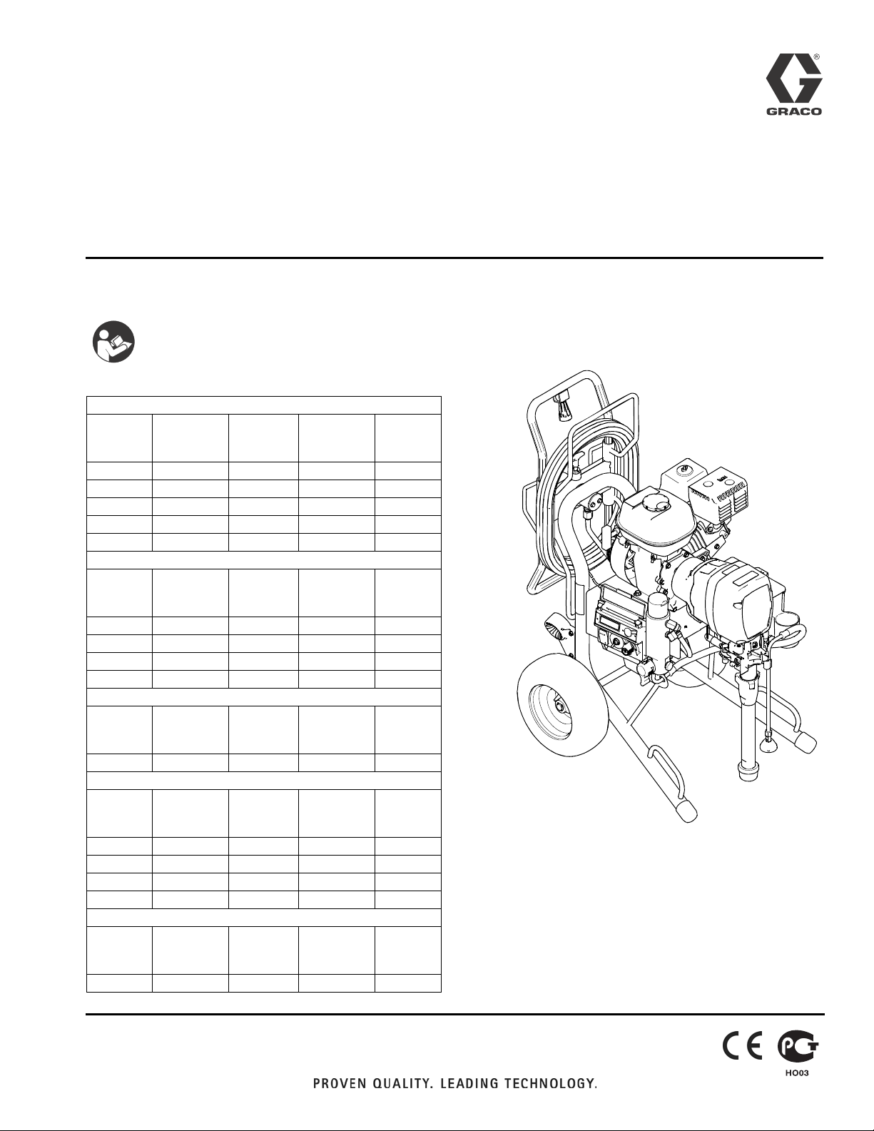
GMAX™ II 3900/5900/7900
™
TexSpray
5900HD/7900HD
Airless Sprayers
Korean patent: 10-0647761
- For Portable Airless Spraying of Architectural Coatings and Paints -
3300 psi (22.8 MPa, 228 bar) Maximum Working Pressure
IMPORTANT SAFETY INSTRUCTIONS
Read all warnings and instructions in this
manual. Save these instructions.
GMAX 3900
Model Hi-Boy
Premium
(QuikReel)
248683 ✓
248684 ✓
249335 ✓
258731 ✓
258736 ✓
Model Hi-Boy
Premium
(QuikReel)
248687 ✓
248688 ✓
258732 ✓
258737 ✓
Model Hi-Boy
Premium
(QuikReel)
258734 ✓
Model Hi-Boy
Premium
(QuikReel)
248700 ✓
248701 ✓
258733 ✓
258738 ✓
Model Hi-Boy
Premium
(QuikReel)
258735 ✓
Hi-Boy
Standard
GMAX 5900
Hi-Boy
Standard
TexSpray 5900 HD
Hi-Boy
Standard
GMAX 7900
Hi-Boy
Standard
GMAX 7900
Hi-Boy
Standard
Lo-Boy
Premium
(QuikReel)
Lo-Boy
Premium
(QuikReel)
Lo-Boy
Premium
(QuikReel)
Lo-Boy
Premium
(QuikReel)
Lo-Boy
Premium
(QuikReel)
Lo-Boy
Standard
Lo-Boy
Standard
Lo-Boy
Standard
Lo-Boy
Standard
Lo-Boy
Standard
3A0243A
ENG
ti14916a
Related Manuals:
Operation 3A0242
Parts 3A0244
Gun 311861
Page 2
Warning
Warning
The following are general warnings related to the setup, use, maintenance and repair of this equipment. Additional,
more specific, warnings may be found throughout the text of this manual, where applicable.
WARNING
FIRE AND EXPLOSION HAZARD
Flammable fumes, such as solvent and paint fumes, in work area can ignite or explode. To help prevent fire and explosion:
• Use equipment only in well ventilated area.
• Do not fill fuel tank while engine is running or hot; shut off engine and let it cool. Fuel is flammable
and can ignite or explode if spilled on hot surface.
• Eliminate all ignition sources; such as pilot lights, cigarettes, portable electric lamps, and plastic
drop cloths (potential static arc).
• Keep work area free of debris, including solvent, rags and gasoline.
• Do not plug or unplug power cords, or turn power or light switches on or off when flammable fumes
are present.
• Ground all equipment in the work area. See Grounding instructions.
• Use only grounded hoses.
• Hold gun firmly to side of grounded pail when triggering into pail.
• If there is static sparking or you feel a shock, stop operation immediately. Do not use equipment
until you identify and correct the problem.
• Keep a working fire extinguisher in the work area.
SKIN INJECTION HAZARD
High-pressure fluid from gun, hose leaks, or ruptured components will pierce skin. This may look like just
a cut, but it is a serious injury that can result in amputation. Get immediate surgical treatment.
• Do not spray without tip guard and trigger guard installed.
• Engage trigger lock when not spraying.
• Do not point gun at anyone or at any part of the body.
• Do not put your hand over the spray tip.
• Do not stop or deflect leaks with your hand, body, glove, or rag.
• Follow the Pressure Relief Procedure when you stop spraying and before cleaning, checking, or
servicing equipment.
• Tighten all fluid connections before operating the equipment.
• Check hoses and couplings daily. Replace worn or damaged parts immediately.
MOVING PARTS HAZARD
Moving parts can pinch, cut or amputate fingers and other body parts.
• Keep clear of moving parts.
• Do not operate equipment with protective guards or covers removed.
• Pressurized equipment can start without warning. Before checking, moving, or servicing equipment, follow the Pressure Relief Procedure and disconnect all power sources.
2 3A0243A
Page 3
Warning
WARNING
PRESSURIZED ALUMINUM PARTS HAZARD
Use of fluids that are incompatible with aluminum in pressurized equipment can cause serious chemical reaction and equipment rupture. Failure to follow this warning can result in death, serious injury, or
property damage.
• Do not use 1,1,1-trichloroethane, methylene chloride, other halogenated hydrocarbon solvents or
fluids containing such solvents.
• Many other fluids may contain chemicals that can react with aluminum. Contact your material supplier for compatibility.
SUCTION HAZARD
Powerful suction could cause serious injury.
• Never place hands near the pump fluid inlet when pump is operating or pressurized.
CARBON MONOXIDE HAZARD
Exhaust contains poisonous carbon monoxide, which is colorless and odorless. Breathing carbon monoxide can cause death.
• Do not operate in an enclosed area.
TOXIC FLUID OR FUMES HAZARD
Toxic fluids or fumes can cause serious injury or death if splashed in the eyes or on skin, inhaled, or
swallowed.
• Read MSDS’s to know the specific hazards of the fluids you are using.
• Store hazardous fluid in approved containers, and dispose of it according to applicable guidelines.
BURN HAZARD
Equipment surfaces and fluid that’s heated can become very hot during operation. To avoid severe
burns:
• Do not touch hot fluid or equipment.
PERSONAL PROTECTIVE EQUIPMENT
You must wear appropriate protective equipment when operating, servicing, or when in the operating
area of the equipment to help protect you from serious injury, including eye injury, hearing loss, inhalation of toxic fumes, and burns. This equipment includes but is not limited to:
• Protective eyewear, and hearing protection.
• Respirators, protective clothing, and gloves as recommended by the fluid and solvent manufacturer.
3A0243A 3
Page 4
Maintenance
Maintenance
Pressure Relief Procedure
1. Lock gun trigger safety.
2. Turn engine ON/OFF switch to OFF.
3. Move pump switch to OFF and turn pressure control
knob fully counterclockwise.
4. Unlock trigger safety. Hold metal part of gun firmly
to side of grounded metal pail, and trigger gun to
relieve pressure.
5. Lock gun trigger safety.
6. Open pressure drain valve. Leave valve open until
ready to spray again.
If you suspect that the spray tip or hose is completely
clogged, or that pressure has not been fully relieved
after following the steps above, VERY SLOWLY loosen
tip guard retaining nut or hose end coupling to relieve
pressure gradually, then loosen completely. Now clear
tip or hose.
AFTER THE FIRST 20 HOURS OF OPERATION:
Drain engine oil and refill with clean oil. Reference
Honda Engines Owner's Manual for correct oil viscosity.
WEEKLY: Remove engine air filter cover and clean element. Replace element, if necessary. If operating in an
unusually dusty environment: check filter daily and
replace, if necessary.
Replacement elements can be purchased from your
local HONDA dealer.
AFTER EACH 100 HOURS OF OPERATION:
Change engine oil. Reference Honda Engines Owner's
Manual for correct oil viscosity.
SPARK PLUG: Use only BPR6ES (NGK) or W20EPR-U
(NIPPONDENSO) plug. Gap plug to 0.028 to 0.031 in.
(0.7 to 0.8 mm). Use spark plug wrench when installing
and removing plug.
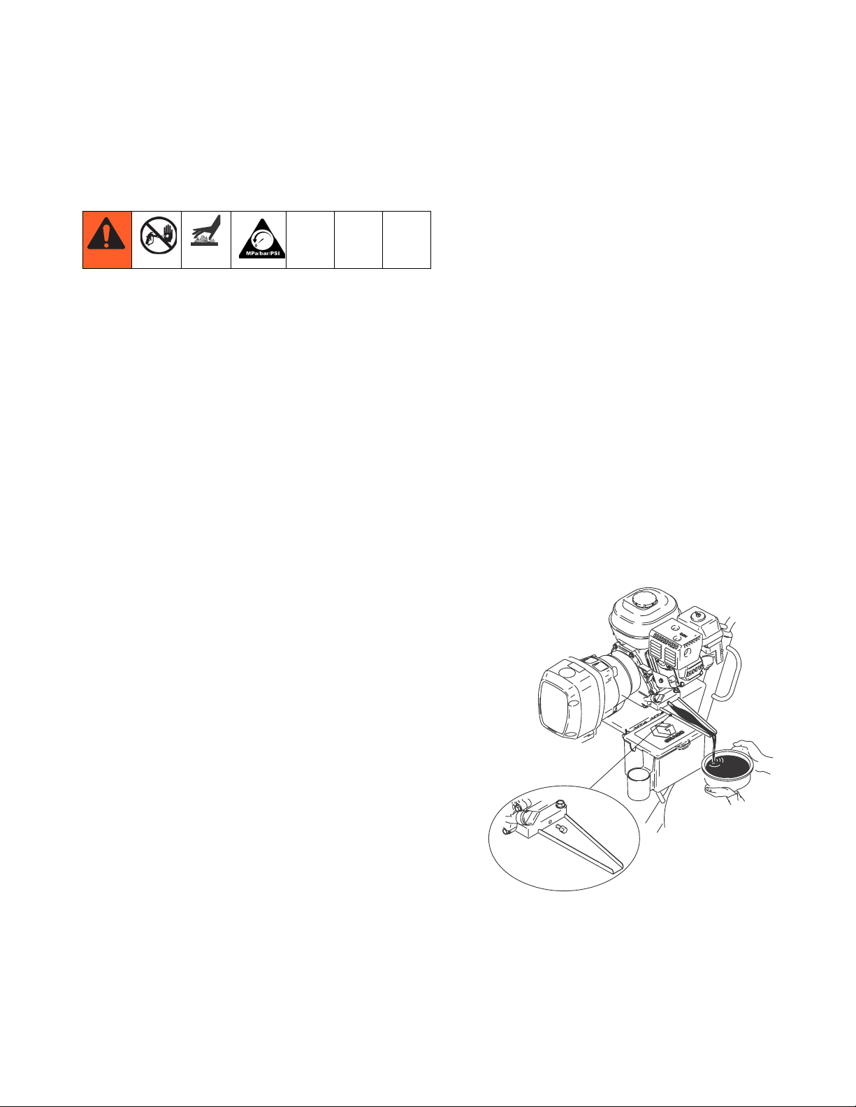
Premium Sprayers Engine Oil Funnel:
Use the supplied engine oil funnel when draining oil.
NOTE: For detailed engine maintenance and specifications, refer to separate Honda Engines Owner's Manual,
supplied.
DAILY: Check engine oil level and fill as necessary.
DAILY: Check hose for wear and damage.
DAILY: Check that all hose fittings are secure.
DAILY: Check gun safety for proper operation.
DAILY: Check pressure drain valve for proper operation.
DAILY: Check and fill the gas tank.
DAILY: Check level of TSL in displacement pump pack-
ing nut. Fill nut, if necessary. Keep TSL in nut to help
prevent fluid buildup on piston rod and premature wear
of packings and pump corrosion.
ti6200a
OIL FUNNEL
4 3A0243A
Page 5
Troubleshooting
Troubleshooting
Problem Cause Solution
E=XX is displayed Fault condition exists. Determine fault correction from table, page 14.
Engine will not start Engine switch is OFF. Turn engine switch ON.
Engine is out of gasoline. Refill gas tank. Honda Engine Manual.
Engine oil level is low. Try to start engine. Replenish oil, if necessary.
Honda Engine Manual.
Spark plug disconnected or damaged. Connect spark plug cable or replace spark
plug.
Engine is cold. Use choke.
Fuel shutoff lever is OFF. Move lever to ON position.
Oil is seeping into combustion chamber. Remove spark plug. Pull starter 3 to 4 times.
Clean or replace spark plug. Start engine.
Keep sprayer upright to avoid oil seepage.
False tripping of WatchDog system.
EMPTY is displayed. Pump does not
run.
Engine operates, but displacement
pump does not operate
Operating conditions out of WatchDog
parameters.
Pump output is low, page 6.
Error code displayed. Reference Pressure Control repair, page 21.
Pump switch is OFF. Turn pump switch ON.
Pressure setting too low. Turn pressure adjusting knob clockwise to
Fluid filter is dirty. Clean filter.
Tip or tip filter is clogged. Clean tip or tip filter (see gun manual).
Displacement pump piston rod is stuck
due to dried paint.
Connecting rod is worn or damaged. Replace connecting rod. Page 15.
Drive housing is worn or damaged. Replace drive housing. Page 16.
Electrical power is not energizing clutch
field.
Turn pressure down. Contact Graco Technical
Assistance to adjust WatchDog parameters.
Operate without WatchDog active (see Opera-
tion manual).
increase pressure.
Repair pump (see pump manual).
Check wiring connections. Page 21.
Reference Digital Display Messages.
Page 14.
Reference wiring diagram. Page 21.
With pump switch ON and pressure turned to
MAXIMUM, use a test light to check for power
between clutch test points on control board.
Remove clutch wires from control board and
measure resistance across clutch coil. At 70° F,
the resistance must be between 1.2 + 0.2 Ω; if
not, replace pinion housing.
Have pressure control checked by authorized
Graco dealer.
Clutch is worn, damaged, or incorrectly
positioned.
Pinion assembly is worn or damaged. Repair or replace pinion assembly. Page 17.
3A0243A 5
Adjust or replace clutch. Page 19.
Page 6

Troubleshooting
Problem Cause Solution
Pump output is low Strainer is clogged. Clean strainer.
Piston ball is not seating. Service piston ball (see pump manual).
Piston packings are worn or damaged. Replace packings (see pump manual).
O-ring in pump is worn or damaged. Replace o-ring (see pump manual).
Intake valve ball is not seating properly. Clean intake valve (see pump manual).
Intake valve ball is packed with mate-
rial.
Engine speed is too low. Increase throttle setting (see operation man-
Clutch is worn or damaged. Adjust or replace clutch. Page 17.
Pressure setting is too low. Increase pressure (see operation manual).
Fluid filter, tip filter or tip is clogged or
dirty.
Large pressure drop in hose with heavy
materials.
Excessive paint leakage into throat
packing nut
Fluid is spitting from gun Air in pump or hose. Check and tighten all fluid connections. Rep-
Pump is difficult to prime Air in pump or hose. Check and tighten all fluid connections.
Throat packing nut is loose. Remove throat packing nut spacer. Tighten
Throat packings are worn or damaged. Replace packings (see pump manual).
Displacement rod is worn or damaged. Replace rod (see pump manual).
Tip is partially clogged. Clear tip (see gun manual).
Fluid supply is low or empty. Refill fluid supply. Prime pump (see operation
Clean intake valve (see pump manual).
ual).
Clean filter (see gun manual).
Use larger diameter hose and/or reduce overall
length of hose. Use of more than 100 ft of 1/4
in. hose significantly reduces performance of
sprayer. Use 3/8 in. hose for optimum performance (50 ft minimum).
throat packing nut just enough to stop leakage.
rime pump (see operation manual).
manual). Check fluid supply often to prevent
running pump dry.
Reduce engine speed and cycle pump as
slowly as possible during priming.
Intake valve is leaking. Clean intake valve. Be sure ball seat is not
nicked or worn and that ball seats well. Reas-
semble valve.
Pump packings are worn. Replace pump packings (see pump manual).
Paint is too thick. Thin the paint according to the supplier's rec-
ommendations.
Engine speed is too high. Decrease throttle setting before priming pump
(see operation manual).
Clutch squeaks each time clutch
engages
High engine speed at no load Misadjusted throttle setting. Reset throttle to 3300 engine rpm at no load.
Gallon counter not working Bad sensor, broken or disconnected
No display, sprayer operates Display damaged or has bad connec-
Clutch surfaces are not matched to
each other when new and may cause
noise.
Worn engine governor. Replace or service engine governor.
wire. Displaced or missing magnet.
tion.
Clutch surfaces need to wear into each other.
Noise will dissipate after a day of run time.
Check connections. Replace sensor or wire.
Reposition or replace magnet.
Check connections. Replace display.
6 3A0243A
Page 7
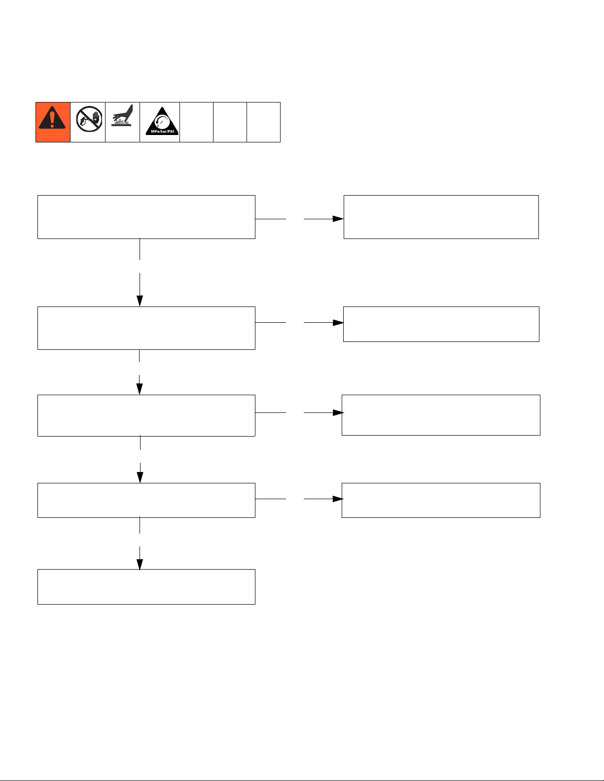
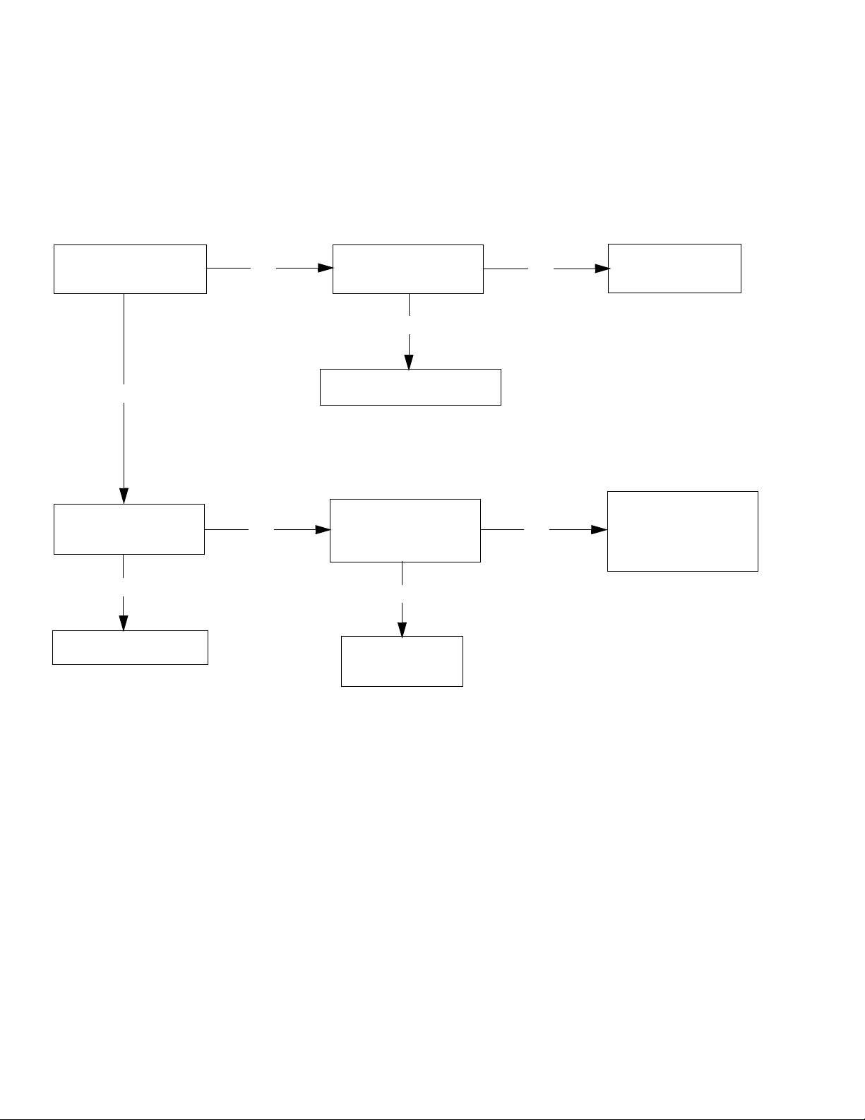
Fluid Pump Runs Constantly
Troubleshooting Procedure:
Troubleshooting
1. Perform Pressure Relief Procedure (page 4), turn
prime valve forward to SPRAY position, and turn
power switch OFF.
2. Remove control box cover.
With a pressure gauge plumbed into the paint
hose, start the engine. Turn pump switch ON.
Does sprayer exceed maximum pressure?
YES
Disconnect clutch wires from control board (see
diagram, page 12). Does the pump stop running?
YES
Make sure clutch wires are plugged in (see diagram, page 12). Do the clutch test points read
10-18 DC volts?
YES
NO
NO
NO
Pump problem. See the proper fluid pump
manual for the sprayer for further troubleshooting procedures.
Mechanical problem in the clutch pinion assembly (clutch may be close to the rotor).
Check for a short from the two clutch wires
to the frame. If shorted, repair or replace
faulty wire.
Unplug transducer from control board.
YES
Bad transducer.
Replace and test with a new one.
3A0243A 7
NO
Replace the control board.
Page 8
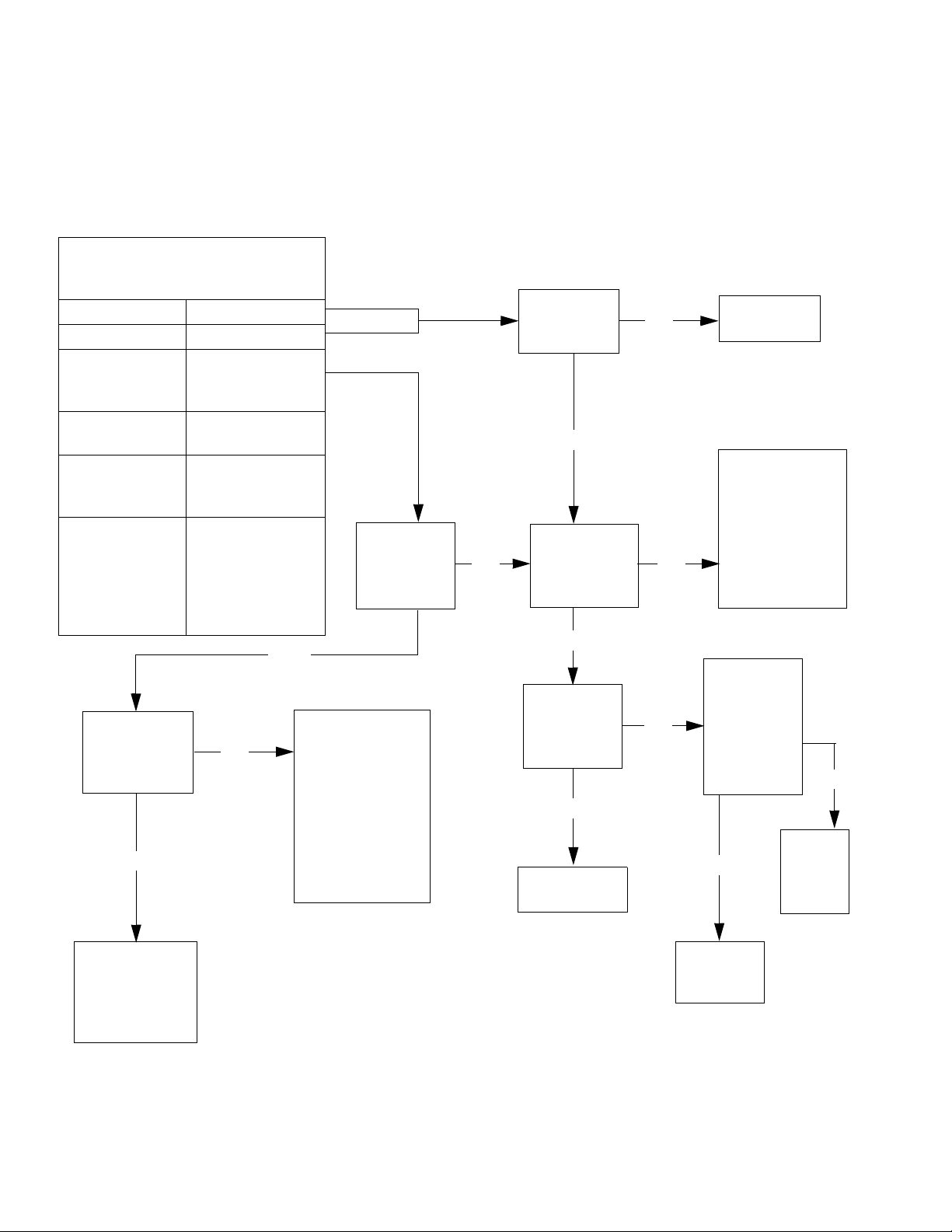
Troubleshooting
Control Board Malfunction
Troubleshooting Procedure
(see following page for actual steps):
Remove control box cover. Turn
sprayer ON. Observe control board
Green and Red LED lights.
No light
Once Normal operation
Red light on
continuously
Green light on
continuously
Flashing See error code
Red light on
continuously with
potentiometer
OFF after a
replacement
board is installed
Go to step 4.
Is 1-3 Ohms
reading present?
YES
Control board
commanding
engine to run
WatchDog
enabled
section for further
troubleshooting
Model not
selected
YES
If low resistance is
NO
present in step 4,
the problem is a
shorted field.
Replace pinion.
If an open in the
wiring is present,
check pinion
wiring
connections.
Go to step 3.
Is 10-12
VDC
present?
NO
Go to step 1.
Does switch
test positive?
YES
Go to step 2.
Do you have
proper engine
voltage?
YES
Go to step 5.
Does the
clutch
engage?
YES
Replace the
potentiometer.
NO
NO
NO
Replace the
switch.
Check wiring
from J1 and J2
for proper connection. If proper
connection is
detected, repair
or replace engine
generator.
Connect
a test
transducer to
the board.
Does the
clutch
engage?
Replace
YES
the
control
board.
NO
Mechanical
problem. Repair
or replace
clutch/pinion
assembly.
8 3A0243A
Replace
the
transducer.
Page 9
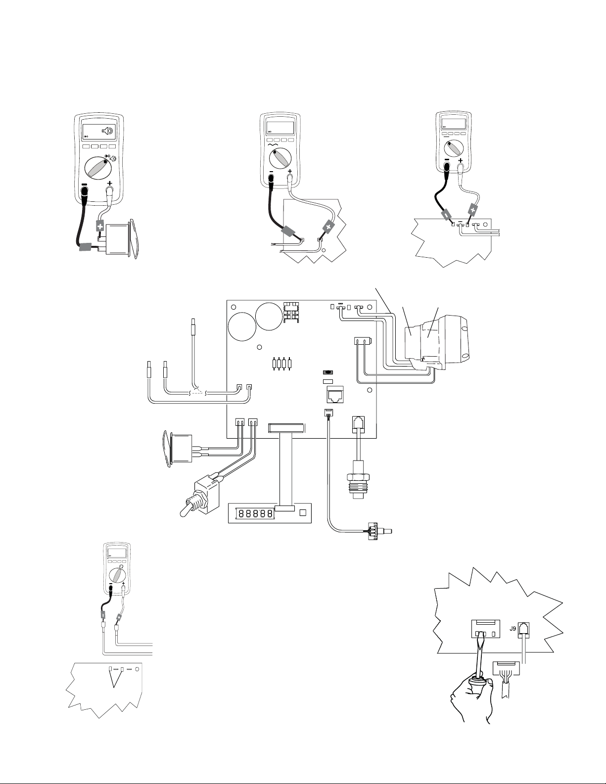
Control Board Malfunction (Steps)
Troubleshooting
BEEP
-
-
+
STEP 1.
Turn engine
OFF and set
meter to
continuity.
ti14938a
Pump
On/Off
Switch
To Ground
To Engine
5900/7900
On/Off Switch
3900
ti14939a
Engine
Generator
J1J2
J4J3
12 -20 AC
V
-
-
Control
Board
STEP 2.
Turn engine
ON. Set meter
to AC volts and
connect wires
to control
board.
Control
Board
+
J1
J2
Clutch Test Points
LED
D12
J5
J10
J9
To Clutch
Field
+
Pinion
Assembly
ti14943a
ti14940a
Control
Board
10-12 DC
V
-
Drive
Housing
STEP 3.
Leave engine
running and turn
switch ON. Turn
potentiometer to
high and set
meter to DC
volts.
+
+
Clutch
Field
WatchDog
Transducer
Premium Display Board
1-3 ohms
STEP 4.
Turn engine
Potentiometer
OFF and
unplug
ti14942a
Control
Board
Clutch Test Points
-
clutch wires.
-
Set meter to
+
Ohms.
+-
Clutch
Field
3A0243A 9
STEP 5.
Turn engine
ON and turn
switch ON.
Control
Board
J5
ti14941a
Page 10
Troubleshooting
Convertible Electric Motor Will Not Run
Troubleshooting Procedure
(see following page for actual steps):
See Step 1. Is there
over 100 AC volts?
YES
See Step 3. Is there
over 100 DC volts?
YES
See engine test section.
NO
NO
See step 2. Is there
over 100 AC volts?
YES
Replace the power switch.
See Step 4. Is there
continuity through the
thermal sensor?
YES
Replace engine
control board.
NO
NO
Repair or replace
the power cord.
If engine is hot, let
cool and retest. If
step 4 still shows an
open, replace engine.
10 3A0243A
Page 11

Convertible Electric Motor Will Not Run (Steps)
Troubleshooting
STEP 1.
Plug in cord and turn
switch ON. Connect
V
wires to control board
and turn meter to AC
volts.
-
ti14920a
+
-
Black
Electric Engine Control Board
L1
L2
White
Ground
Black
Black
Transformer
White
Black
Black
STEP 2.
Plug in cord and turn
switch ON. Connect
wires to control board
and turn meter to AC
volts.
power cord
Jack
Power Cord
AC power to
control board
Black to
V
-
ti14921a
-
Black
Electric Engine Control Board
White to Barrel
Black to Tips
L1
L2
+
White
100 + DC
V
-
+
+M -M
Electric
Engine
STEP 3.
Plug in cord and turn
switch ON. Turn meter
to DC volts.
Engine
-
Control
Board
TS TS
ti14923a
Ye l l o w Ye l l o w
Engine Control Board
Black
+M -M
ti14924a
Electric
Engine
White
L1
L2
TS TS
BEEP
STEP 4.
Check the engine thermal sensor (meter
should read continuity).
Note: engine should
-
be cooled down. Turn
meter to continuity test.
Engine
Control
TS
-
Board
TS
ti14922a
+M
Electric
Engine
-M
3A0243A 11
Page 12

Troubleshooting
Convertible Electric Motor Runs No AC Output to Sprayer Control Board
Troubleshooting Procedure
(see following page for actual steps):
See step 1.
Is there over 10-20
AC volts?
YES
See the sprayer
control board troubleshooting in this
manual.
NO
See step 2.
Is there continuity?
YES
See step 3.
Is there continuity?
YES
See step 4.
Is there over 100
AC volts?
YES
See step 5.
Is there over
10-20 AC volts.
NO
NO
NO
NO
Repair or replace
the power cord.
Repair or replace
the power cord.
Repair or replace
wire splice(s) on
the power cord
wires.
Replace transformer.
YES
Replace cord jack.
12 3A0243A
Page 13

Troubleshooting
Convertible Electric Motor Runs - No AC Output to Sprayer Control Board (Steps)
10-20 AC
V
-
ti14925a
Jack
Transformer
STEP 1.
Plug in cord and turn
switch ON. Connect
wires to transformer
and power cord. Turn
meter to AC volts.
-
Power Cord
AC power to
control board
Ground
Ground
+
Black
Black
White to barrel
Black to tips
Transformer
Black
Black
Black
White
Engine Control Board
L1
+M -M
Jack
L2
TS TS
Power Cord
AC power to
control board
White
ti14926a
-
ti14927a
White to barrel
Black to tips
BEEP
-
-
STEP 2.
Check AC power cord
for an open wire. Turn
meter to continuity
test. Meter should
read continuity.
Power Cord
AC power to
control board
STEP 3.
BEEP
Check AC power
cord for an open
wire. Turn meter to
continuity test.
-
Meter should read
continuity.
Power Cord
AC power to
control board
White to barrel
Black to tips
White to barrel
Black to tips
Power
Cord
STEP 4.
Plug in cord and turn
switch ON. Partially
V
connect wires to
splice. Turn meter to
-
-
Black
AC volts.
Tr a ns f or m e r
+
White
L1
Electric Engine Control Board
ti14929a
L2
ti14930a
Electric
Engine
White
10-20 AC
V
-
STEP 5.
Plug in cord and
turn switch ON.
Partially connect
wires to splice.
Turn meter to AC
volts.
ti14928a
Transformer
+
Black
Black
Black
-
Jack
3A0243A 13
Page 14

Digital Display Messages
Digital Display Messages
• Digital messages are not available on all sprayers
• Blinking LED total count equals digital error code
i.e., two blinks is the same as E=02
DISPLAY* SPRAYER OPERATION INDICATION ACTION
No Display Sprayer may be
pressurized.
Sprayer may be
ti6314a
pressurized.
Loss of power or display
not connected.
Pressure less than
200 psi (14 bar, 1.4 MPa).
Check power source. Relieve pressure before repair
or disassembly. Verify display is connected.
Increase pressure as needed.
psi
bar
MPa
ti6315a
ti6316a
ti6317a
ti6318a
(with
constant
green LED)
ti6320a
Sprayer is pressurized.
Power is applied.
(Pressure varies with tip
size and pressure
control setting).
Sprayer stops. Engine is
running.
Sprayer stops. Engine is
running.
Sprayer stops. Engine is
running.
Sprayer stops. Engine is
running.
Sprayer stops. Engine is
running.
Normal operation. Spray
Exceeded pressure limit. 1. Check fluid path for clogs, such as clogged filter.
2. Open prime valve and gun if running AutoClean.
3. Use Graco paint hose, 1/4 in. x 50 ft minimum.
Smaller hose or metal braid hose may result in
pressure spikes.
4. Replace transducer if fluid path is not clogged
and proper hose is used.
Pressure transducer faulty,
bad connection or broken
wire.
1. Check transducer connection.
2. Disconnect and reconnect transducer plug to
ensure good connection with control board
socket.
3. Open prime valve. Replace sprayer transducer
with known good transducer and run sprayer.
Replace transducer if sprayer runs or control
board if sprayer does not run.
High clutch current. 1. Check wiring connections.
Measure: 1.2 + 0.2 Ω (GMAX II 3900);
2.
1.7 + 0.2 Ω (GMAX II 5900/ 7900 & TexSpray
7900HD) across clutch field at 70°F.
3. Replace clutch field assembly.
Loss of paint to pump or
severe pressure loss.
1. Check for empty paint condition, clogged inlet
strainer, failed pump or severe leak.
2. Reduce pressure and turn pump switch OFF
and ON to restart pump.
3. WatchDog function can be deactivated by
turning WatchDog switch OFF.
Pressure greater than
2000 psi (138 bar, 14 MPa)
while in Flush Timer Mode.
1. Open prime valve and gun.
2. Verify no flow obstructions or clogged filter.
* Error codes also appear on control board as a blinking red
LED. LED is an alternate to digital messages.
1. Remove two screws (71) and swing down cover (130).
2. Start engine. Blink count is the same as error code(E=0X).
After a fault, follow these steps to restart sprayer:
1. Correct fault condition
2. Turn sprayer OFF
3. Turn sprayer ON
14 3A0243A
Page 15

Bearing Housing and Connecting Rod
NOTE: The item numbers referenced are for the 5900
Hi-Boy models. The 3900, 7900 and all Lo-Boy models
may have different item numbers. Use the 5900 Hi-Boy
item number and part to find the corresponding alternate part and item number.
Bearing Housing and Connecting Rod
NOTICE
DO NOT use bearing housing screws (41) to align or
seat bearing housing with drive housing. Align these
parts with locating pins, to avoid premature bearing
wear.
Removal
1. Relieve pressure; page 4.
2. Remove four screws (45) and front cover (44)
3. Remove pump. Refer to Displacement Pump,
Removal, page 23.
4. Remove four screws (41) and washers (42) from
bearing housing (40).
5. Pull connecting rod (43) and lightly tap lower rear of
bearing housing with plastic mallet to loosen from
drive housing (33). Pull bearing housing and connecting rod assembly off drive housing.
6. Inspect crank (B) and connecting rod (43) for excessive wear and replace parts as needed.
Installation
5. Install screws (41) and washers (42) in bearing
housing. Torque evenly to note 3 value below.
6. Install pump. Refer to Displacement Pump,
Installation, page 14.
"
%
$
&
#
!
TIB
1. Evenly lubricate inside of bronze bearing (C) in
bearing housing (40) with high-quality motor oil. Liberally pack top roller bearing (E), lower bearing (D)
inside connecting rod (43) with bearing grease.
2. Assemble connecting rod (43) to bearing housing
(40). Rotate connecting rod to lowest position.
3. Clean mating surfaces of bearing and drive hous-
Oil
1
Pack with bearing grease 114819
2
GMAX II 3900: Torque to 200 in-lb (22.6 N•m)
3
GMAX II 5900: Torque to 25 ft-lb (34 N•m)
GMAX II 7900: Torque to 40 ft-lb (54 N•m)
TexSpray 5900HD: Torque to 40 ft-lb (54 N•m)
TexSpray 7900HD: Torque to 40 ft-lb (54 N•m)
ings.
4. Align connecting rod with crank (B) and carefully
align locating pins (F) in drive housing (33) with
holes in bearing housing (40). Push bearing housing
onto drive housing or tap into place with plastic mallet.
3A0243A 15
Page 16

Drive Housing
Drive Housing
Removal
1. Relieve pressure; page 4.
2. Remove bearing housing. Refer to Bearing Hous-
ing and Connecting Rod, Removal, page 15.
NOTICE
Premium models: Gallon counter sensor is connected to
control board in pressure control. Pulling on the sensor
wires could cause damage.
3. Premium sprayers: Remove two screws (108) and
gallon counter sensor (39).
NOTICE
Thrust washers may stick to grease inside of drive
housing. Do not lose or misplace.
4. Remove six screws (38).
5. Lightly tap around drive housing (33) to loosen drive
housing. Pull drive housing straight off pinion housing. Be prepared to support combination gear (32)
which may also come out.
7. Install bearing housing. Refer to Bearing Housing
and Connecting Rod, Installation, page 15.
NOTICE
DO NOT use drive housing screws (38) to align or seat
drive housing with pinion housing. Align these parts with
locating pins, to avoid premature bearing wear.
8. Install screws (38) in drive housing. Torque evenly to
note 3 value below.
9. Install pump. Refer to Displacement Pump,
Installation, page 14.
"
TIA
"
A
B
1
Installation
1. Apply all grease supplied with replacement gear
cluster to gear teeth and to areas called out by note
3.
2. Ensure thrust washers (30, 31; 5900/7900) (30, 31,
72; 3900) are on combination gear (32) and wash-
GMAX II 3900: Torque to 140 ±10 in-lb (15.8 ±1.1 N•m)
1
GMAX II 5900: Torque to 200 ±10 in-lb (22.6 ±1.1 N
GMAX II 7900: Torque to 200 ±10 in-lb (22.6 ±1.1 N
Texspray 5900HD: Torque to 200 ±10 in-lb (22.6 ±1.1 N
Texspray 7900HD: Torque to 200 ±10 in-lb (22.6 ±1.1 N
Gallon counter sensor
2
Pack with grease 114819
3
•m)
•m)
•m)
•m)
ers (33a, 33b) are on crankshaft of drive housing
(33) as shown.
3. Clean mating surfaces of pinion and drive housings.
4. Align gears and push new drive housing straight
onto pinion housing (29) and locating pins (B).
5. Install six screws (38).
6. Install gallon counter sensor (39) with two screws
(108).
16 3A0243A
TIA
1
2
Copper
Steel
Page 17

Pinion Assembly/Clutch Armature/Clamp
Pinion Assembly/Clutch Armature/Clamp
Pinion Assembly/Clutch Armature Removal
Pinion Assembly
If pinion assembly (29) is not removed from clutch housing (19), do 1. through 3. Otherwise, start at 4.
1. Remove drive housing; page 16.
2. Disconnect clutch cable connectors from inside of
pressure control.
a. Remove two screws (71) and swing down cover
(130a).
b. Disconnect engine leads from board to engine.
c. Remove strain reliefs 130r and 123.
3. Remove four screws (36) and pinion assembly (29).
36
37
19
29
6. Remove retaining ring (29b).
7. Turn pinion assembly over and tap pinion shaft
(29a) out with plastic mallet.
27
29b
29a
29d
ti5482a
Clutch Armature
8. Use an impact wrench or wedge something
between clutch armature (25) and clutch housing to
hold engine shaft during removal.
9. Remove four screws (23) and lock washers (24).
36
37
ti5480a
4. Place pinion assembly (29) on bench with rotor side
up.
5. Remove four screws (28) and lock washers (24).
Install two screws in threaded holes (E) in rotor.
Alternately tighten screws until rotor comes off.
28
24
E
29
ti5481a
E
ti5987b
10. Remove armature.
TIA
3A0243A 17
Page 18

Pinion Assembly/Clutch Armature/Clamp
Installation
Clutch Armature
1. Lay two stacks of two dimes on smooth bench surface.
2. Lay armature (25) on two stacks of dimes.
3. Press center of hub (26) down to bench surface.
25
ti6321a
26
0.12+01 in (3.0+.25 mm)
dimes
4. Install armature (25) on engine drive shaft.
5. Install four screws (23) and lock washers (24) with
torque of 125 in-lb.
Clamp Removal
1. Remove engine.
Pinion Assembly
1. Check o-ring (29d) and replace if missing or damaged.
2. Tap pinion shaft (29a) in with plastic mallet.
3. Install retaining ring (29b) with beveled side facing
up.
4. Place pinion assembly on bench with rotor side up.
5. Apply thread sealant to screws. Install four screws
(28) and lock washers (24). Alternately torque
screws to 125 in-lb until rotor is secure. Use
threaded holes to hold rotor.
6. Install pinion assembly (29) with four screws (36)
and washers (37).
7. Connect clutch cable connectors to inside of pressure control.
3. Check dimension: Place rigid, straight steel bar (B)
across face of clutch housing (19). Use accurate
measuring device to measure distance between bar
and face of clamp. Adjust clamp as necessary.
Torque two screws (24) to 125 ±10 in-lb (14 ±1.1
N·m).
2. Drain gasoline from tank according to Honda manual.
3. Tip engine on side so gas tank is down and air
cleaner is up.
4. Loosen two screws (24) on clamp (22),
5. Push screwdriver into slot in clamp (22) and remove
clamp.
ti6199a
Clamp Installation
1. Install engine shaft key (18).
2. Tap clamp (22) onto engine shaft (A). Maintain
dimension shown note 2. Chamfer must face
engine.
1
Face of clutch housing
1.550 ± .010 in. (39.37 ± .25 mm) - GMAX 3900
2
2.612 ± .010 in. (66.34 ± .25 mm) - GMAX 5900 & 7900
Torque to 125 ±.10 in-lb (14 ±1.1 N·m)
3
Chamfer this side
4
19
TIA
"
!
18 3A0243A
Page 19
Clutch Housing
Removal
1. Remove four screws (20) and lock washers (21)
which hold clutch housing (19) to engine.
2. Remove screw (35) from under mounting plate (D).
3. Pull off clutch housing (19).
Installation
1. Push on clutch housing (19).
Clutch Housing
2. Install four capscrews (20) and lock washers (21)
and secure clutch housing (19) to engine. Torque to
200 in-lb (22.6 N·m).
3. Install screw (35) from beneath mounting plate (D).
Torque to 26 ft-lb (35.2 N·m).
19
21
20
ti5486a
18
D
35
3A0243A 19
Page 20

Clutch Housing
Removal
Engine
NOTE: All service to the engine must be performed by
an authorized Honda dealer.
1. Remove Pinion Assembly/Clutch Arma-
ture/Clamp and Clutch Housing, as instructed on
pages 17, and 18.
2. Disconnect all necessary wiring.
3. Remove two locknuts (17) and screws (16) from
base of engine.
4. Lift engine carefully and place on work bench.
1
To the field
2
To the engine
3
To gallon counter
3
4
To ground
1
Bottom View
3900
Green
16
ti5487a
17
Installation
1. Lift engine carefully and place on cart.
2. Install two screws (16) in base of engine and secure
with lock nuts (17). Torque to 26 ft-lb (22.6 N·m).
3. Connect all necessary wiring.
4. Install Pinion Assembly/Clutch Armature/Clamp
and Clutch Housing, as instructed on pages 17,
and 18.
ti5485b
2
4
2
Bottom View
5900/7900
20 3A0243A
Page 21

Pressure Control
Pump ON/OFF Switch
Pressure Control
Removal
1. Remove two screws (71) and swing down
cover (130a).
2. Disconnect pump ON/OFF switch (130f) connector
from control board.
CLUTCH (-)
TO ENGINE 15
5900/7900
CLUTCH (+)
3. Press in on two retaining tabs on each side of pump
ON/OFF switch (130f) and remove switch from
cover.
Installation
1. Install new pump ON/OFF switch (130f) so tabs of
switch snap into place on inside of cover.
2. Connect pump ON/OFF switch connector to control
board.
3. Swing up cover (130a) and secure with two screws
(71).
GROUND 129
3900
130a
130r
130c
123
130f
130g
CLUTCH
39 GALLON COUNTER
130b
66
130a
130f
72
130j
130d
130h
71
3A0243A 21
113
66
67
ti14915a
130d
130e
Page 22
Pressure Control
Control Board
Removal
1. Remove two screws (71) and swing down
cover (130a).
2. Remove strain relief bushings (130r and 123).
3. Disconnect at control board (130b):
• Lead from potentiometer (130d)
• Lead from transducer (66)
• Lead from WatchDog switch (130g)
• Lead from pump ON/OFF switch (130f)
• Lead from gallon counter sensor (39)
• Display connector (130m)
• Engine, ground and clutch wires
4. Remove four screws (130c) and control board (130b).
Pressure Control Transducer
Removal
1. Remove two screws (71) and swing down
cover (130a).
2. Disconnect transducer (66) lead from control board
(130b).
3. Pull transducer connector through rubber grommet (113).
Installation
1. Install control board (130b) with four screws (130c).
2. Connect engine wires to control board (130b).
3. Connect at control board (130b):
• Ground and clutch wires
• Display connector (130m)
• Lead from gallon counter sensor (39)
• Lead from pump ON/OFF switch (130f)
• Lead from WatchDog switch (130g)
• Lead from transducer (66)
• Lead from potentiometer (130d)
4. Install new strain relief bushings (123 and 130r).
5. Swing up cover (130a) and secure with two screws (71).
4. Remove pressure control transducer (66) and o-ring (67)
from filter housing (72).
Installation
1. Install o-ring (67) and pressure control transducer (66) in
filter housing (72). Torque to 35 - 45 ft-lb.
2. Install transducer connector and rubber grommet in control housing.
3. Connect transducer (66) lead to control board (130b).
4. Swing up cover (130a) and secure with two screws (71).
Pressure Adjust Potentiometer
Removal
1. Remove two screws (71) and swing down
cover (130a).
2. Disconnect potentiometer (130d) lead from control board
(130b).
3. Loosen set screws on potentiometer knob (130h) and
remove knob, shaft nut, lock washer and potentiometer
(130d).
4. Remove shaft spacer (130e) from potentiometer.
22 3A0243A
Installation
1. Install shaft spacer (130e) on potentiometer (130d).
2. Install potentiometer, shaft nut, lock washer and potentiometer knob (130h).
a. Turn potentiometer shaft clockwise to internal stop.
Assemble potentiometer knob (130h) to strike pin on
cover (130a).
b. After adjustment of step a., tighten both set screws in
knob 1/4 to 3/8 turn after contact with shaft.
3. Connect potentiometer lead to control board (130b).
4. Swing up cover (130a) and secure with two screws (71).
After a fault, follow these steps to restart sprayer:
1. Correct fault condition.
2. Turn sprayer OFF.
3. Turn sprayer ON.
Page 23
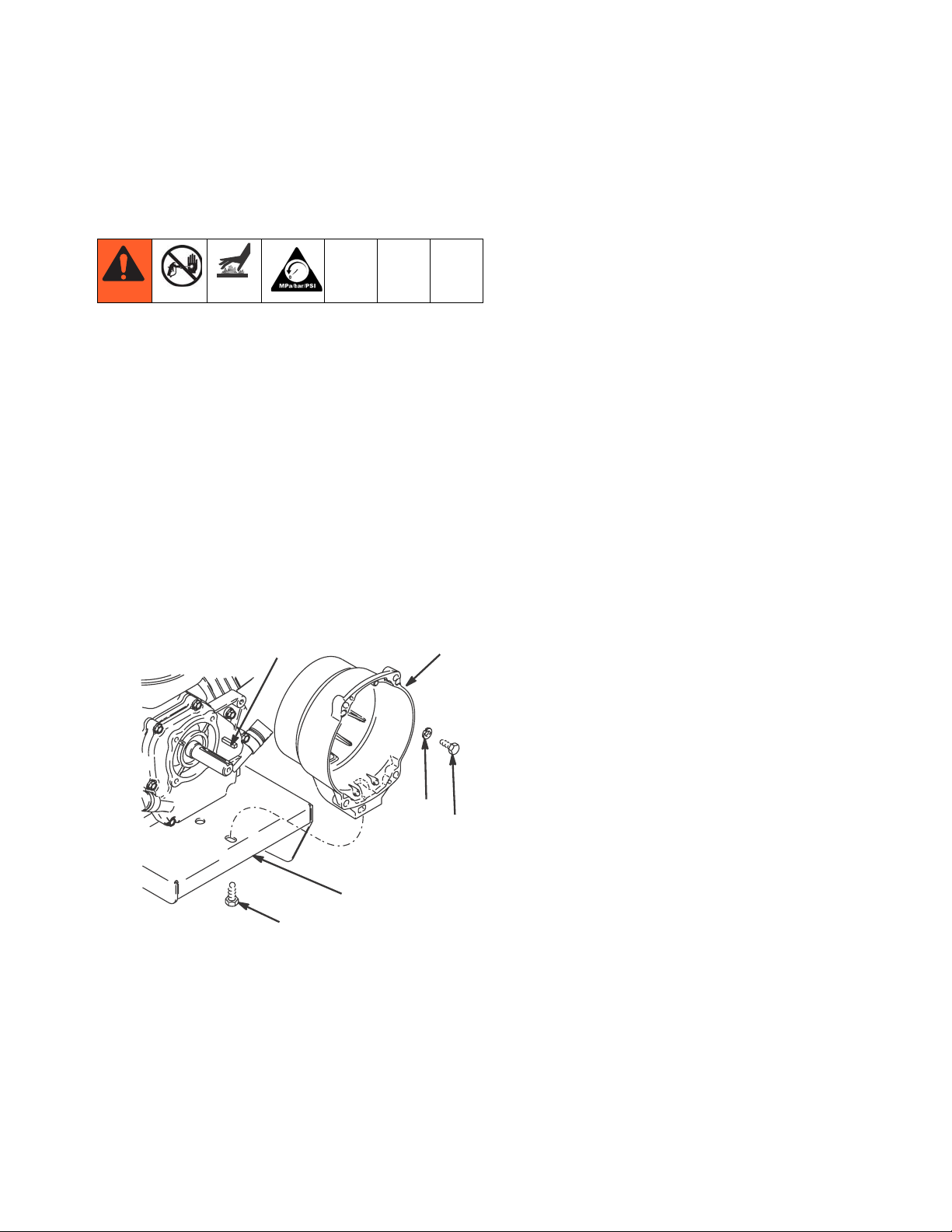
Displacement Pump
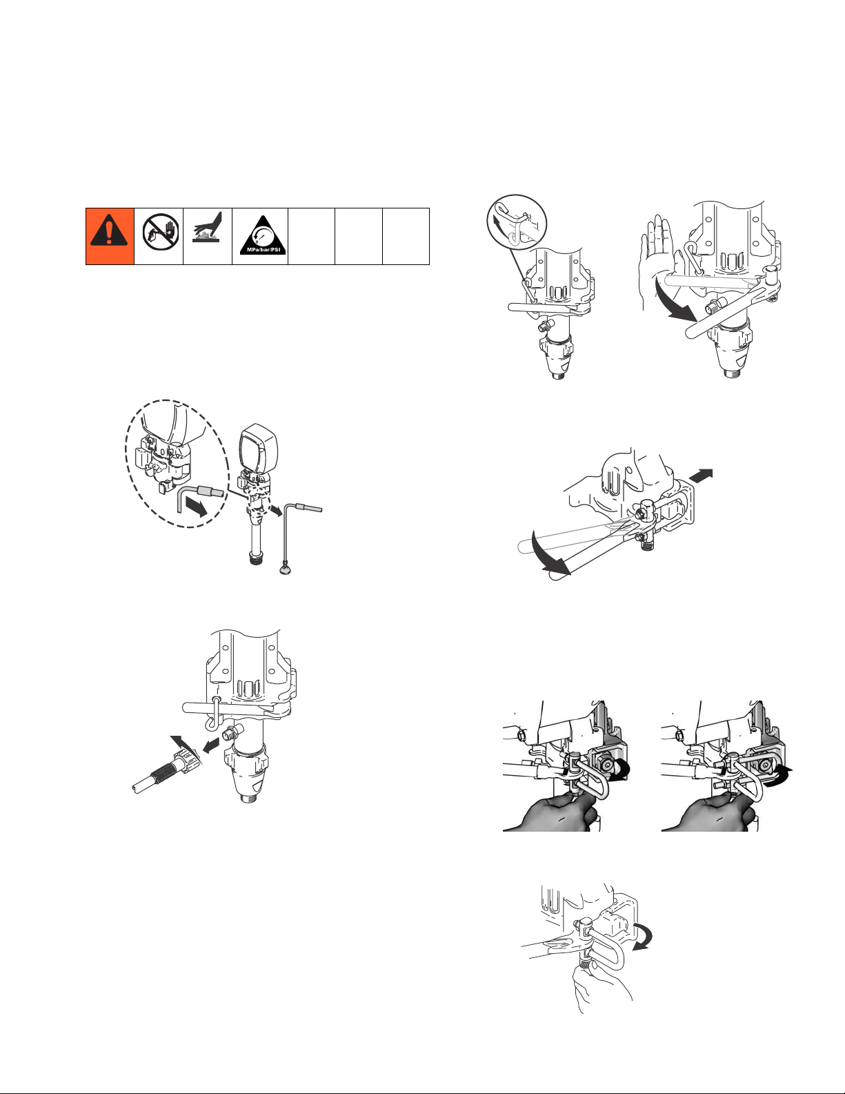
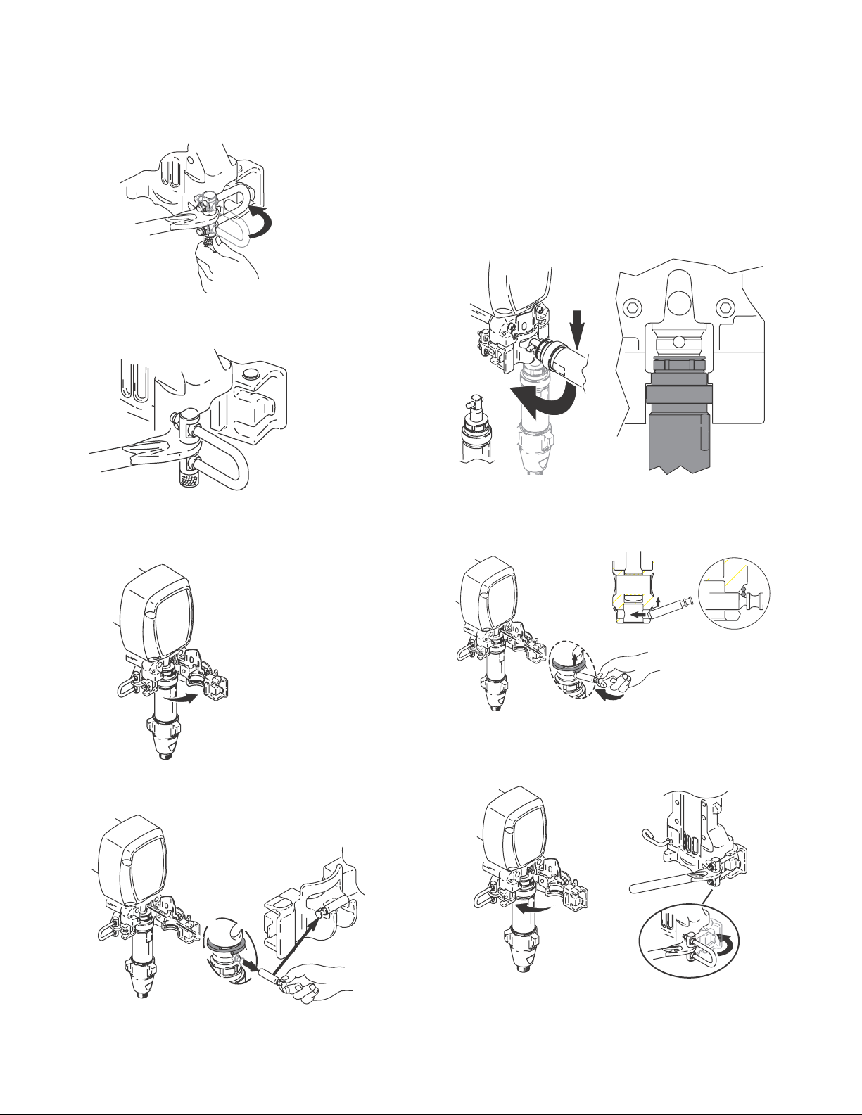
Displacement Pump
Removal
1. Flush pump.
2. Stop pump with piston rod in its lowest position.
3. Do Pressure Relief, page 4.
4. Separate drain hose from sprayer.
ti14904a
6. Raise latch lock. Push latch open.
ti6369a
ti11422a
ti6370a
7. Ratchet open pump door.
a. Ratchet pump door forward.
ti6373a
5. Disconnect material hose from pump.
ti6300a
b. Twist latch u-bolt out of pump door recess.
c. Place u-bolt on pump door outer edge.
d. If pump door is stuck, do steps e., f. and 8., oth-
erwise go to step 9.
ti11425a ti11426a
e. Twist latch u-bolt back from pump door outer
edge
ti6374a
3A0243A 23
Page 24
Displacement Pump
f. Place u-bolt on pump door protrusion
ti6375a
8. Ratchet pump door forward.
9. Open pump door.
Installation
1. Adjust piston rod with pin holder to pull out piston
rod. Tap piston rod on hard surface to push in piston
rod.
2. Push pump collar flush with bearing housing ledge
to be able to close pump door.
ti6325a
ti5492a
3. Slide pump into connecting rod. Push pump pin until
it is fully retained.
NOTE: Pin will snap into position.
ti14905a
10. Pull out pump pin and place in pin holder
ti6378a
ti14907a
4. Close pump door and rotate latch into position. Do
not tighten latch.
ti6313a
ti14908a
ti14906a
24 3A0243A
Page 25

Displacement Pump
5. Rotate pump to align with material hose. Connect
material hose and hand tighten to 70 in-lb.
ti6299a
6. Tighten latch and rotate latch lock into locked position.
ti6204a
7. Attach drain hose to sprayer.
ti14909a
8. Fill pump with Graco TSL until fluid flows onto top
of seal.
ti5493a
ti6312a
TI6312a
ti6204a
3A0243A 25
Page 26

Hose Reel
Hose Reel
Removal
Be sure to keep your head clear of hose reel while
winding up hose.
4. Remove swivel cap.
1. Remove hose fitting from swivel cap and completely
remove hose.
ti15023a
2. Remove cap from swivel.
ti13675a
3. Remove E-clip from swivel shaft.
ti13543a
5. Remove snap ring.
ti13542a
6. Remove hose reel.
ti15024a
ti13538a
26 3A0243A
Page 27

Installation
Hose Reel
1. Grease shaft.
ti13537a
2. Make sure two washers and wave spring are on hub
before hose reel is installed.
ti13545a
3. Install hose reel onto frame. Place C-clamp on reel
and frame to allow snap ring to fit into place. Install
snap ring.
5. Install E-clip.
ti13538a
6. Install hose to hose cap. Make sure to route hose
through side arm of hose reel.
ti15023a
7. Wrap up hose. Make sure hose is routed through
hose guide.
ti13536a
4. Install swivel cap.
ti13543a
3A0243A 27
ti13504a
Page 28

Pivot Replacement
Pivot Replacement
Removal
1. Remove Hose Reel, page 26.
2. Remove rigid fluid tube from swivel shaft.
ti15025a
3. Remove two screws on pivot plate (A), swivel shaft
(B) if necessary, and remove coupling (C) from
swivel shaft.
B
D
Installation
1. Install pivot (D).
2. Install pivot plate (A) on pivot and tighten two screws
on pivot plate.
B
D
A
C
3. Install o-ring and replace swivel shaft (B) if it was
removed.
ti13544a
4. Replace coupling (C).
ti15022a
B
A
C
4. Remove pivot (D).
ti15022a
5. Replace rigid fluid tube to swivel shaft if it was
removed.
ti15025a
6. Replace Hose Reel, page 27.
28 3A0243A
Page 29

Technical Data
Technical Data
Honda GX120 Engine
ANSI Power Rating @ 3600 rpm 4.0 Horsepower (3.0 kW)
Honda GX160 Engine
ANSI Power Rating @ 3600 rpm 5.5 Horsepower (4.1 kW)
Honda GX 200 Engine
ANSI Power Rating @ 3600 rpm 6.5 Horsepower (4.8 kW)
Maximum working pressure 3300 psi
(228 bar, 22.8 MPa)
Noise Level
Sound power 105 dBa
per ISO 3744
Sound pressure 96 dBa
measured at 3.1 feet (1 m)
Maximum delivery rating
3900 1.25 gpm (4.73 liter/min)
5900/5900HD 1.60 gpm (6.06 liter/min)
7900 2.20 gpm (8.33 liter/min)
Maximum tip size
3900 1 gun with 0. 036 in. tip
2 guns with 0. 023 in. tip
3 guns with 0. 018 in. tip
5900/5900HD 1 gun with 0. 043 in. tip
2 guns with 0. 029 in. tip
3 guns with 0. 023 in. tip
4 guns with 0. 019 in. tip
7900 1 gun with 0. 048 in. tip
2 guns with 0. 035 in. tip
3 guns with 0. 027 in. tip
4 guns with 0. 023 in. tip
Inlet paint strainer 12 mesh (893 micron)
stainless steel screen, reusable
Outlet paint filter 60 mesh (250 micron)
stainless steel screen, reusable
Pump inlet size 1-5/16–12 UN-2A
Fluid outlet size: 3900/5900 ¼ npsm from fluid filter
Fluid outlet size: 7900 3/8 npsm from fluid filter
Wetted parts zinc-plated carbon steel, PTFE, nylon, polyurethane, UHMW
polyethylene, fluoroelastomer, acetal, leather, aluminum, tung-
sten carbide, nickel- and zinc-plated carbon steel, stainless
steel, chrome plating
3A0243A 29
Page 30

Technical Data
Dimensions
Sprayer
(no hose and gun)
3900 109 (50) 31.5 (80.0) 22.25 (56.5) 32.0 (81.3)
5900 139 (64) 32.25 (81.9) 24.5 (62.2) 32.25 (81.9)
7900 146 (67) 32.25 (81.9) 24.5 (62.2) 33.0 (83.8)
TexSpray 7900HD 157 (71) 32.25 (81.9) 24.5 (62.2) 33.0 (83.8)
Weight lb (kg) Height in. (cm) Width in. (cm) Length in. (cm)
30 3A0243A
Page 31

Notes
Notes
3A0243A 31
Page 32

Graco Standard Warranty
Graco warrants all equipment referenced in this document which is manufactured by Graco and bearing its name to be free from defects in
material and workmanship on the date of sale to the original purchaser for use. With the exception of any special, extended, or limited warranty
published by Graco, Graco will, for a period of twelve months from the date of sale, repair or replace any part of the equipment determined by
Graco to be defective. This warranty applies only when the equipment is installed, operated and maintained in accordance with Graco’s written
recommendations.
This warranty does not cover, and Graco shall not be liable for general wear and tear, or any malfunction, damage or wear caused by faulty
installation, misapplication, abrasion, corrosion, inadequate or improper maintenance, negligence, accident, tampering, or substitution of
non-Graco component parts. Nor shall Graco be liable for malfunction, damage or wear caused by the incompatibility of Graco equipment with
structures, accessories, equipment or materials not supplied by Graco, or the improper design, manufacture, installation, operation or
maintenance of structures, accessories, equipment or materials not supplied by Graco.
This warranty is conditioned upon the prepaid return of the equipment claimed to be defective to an authorized Graco distributor for verification of
the claimed defect. If the claimed defect is verified, Graco will repair or replace free of charge any defective parts. The equipment will be returned
to the original purchaser transportation prepaid. If inspection of the equipment does not disclose any defect in material or workmanship, repairs will
be made at a reasonable charge, which charges may include the costs of parts, labor, and transportation.
THIS WARRANTY IS EXCLUSIVE, AND IS IN LIEU OF ANY OTHER WARRANTIES, EXPRESS OR IMPLIED, INCLUDING BUT NOT LIMITED
TO WARRANTY OF MERCHANTABILITY OR WARRANTY OF FITNESS FOR A PARTICULAR PURPOSE.
Graco’s sole obligation and buyer’s sole remedy for any breach of warranty shall be as set forth above. The buyer agrees that no other remedy
(including, but not limited to, incidental or consequential damages for lost profits, lost sales, injury to person or property, or any other incidental or
consequential loss) shall be available. Any action for breach of warranty must be brought within two (2) years of the date of sale.
GRACO MAKES NO WARRANTY, AND DISCLAIMS ALL IMPLIED WARRANTIES OF MERCHANTABILITY AND FITNESS FOR A
PARTICULAR PURPOSE, IN CONNECTION WITH ACCESSORIES, EQUIPMENT, MATERIALS OR COMPONENTS SOLD BUT NOT
MANUFACTURED BY GRACO. These items sold, but not manufactured by Graco (such as electric motors, switches, hose, etc.), are subject to
the warranty, if any, of their manufacturer. Graco will provide purchaser with reasonable assistance in making any claim for breach of these
warranties.
In no event will Graco be liable for indirect, incidental, special or consequential damages resulting from Graco supplying equipment hereunder, or
the furnishing, performance, or use of any products or other goods sold hereto, whether due to a breach of contract, breach of warranty, the
negligence of Graco, or otherwise.
FOR GRACO CANADA CUSTOMERS
The Parties acknowledge that they have required that the present document, as well as all documents, notices and legal proceedings entered into,
given or instituted pursuant hereto or relating directly or indirectly hereto, be drawn up in English. Les parties reconnaissent avoir convenu que la
rédaction du présente document sera en Anglais, ainsi que tous documents, avis et procédures judiciaires exécutés, donnés ou intentés, à la suite
de ou en rapport, directement ou indirectement, avec les procédures concernées.
For the latest information about Graco products, visit www.graco.com.
TO PLACE AN ORDER, contact your Graco distributor or call 1-800-690-2894 to identify the nearest distributor.
All written and visual data contained in this document reflects the latest product information available at the time of publication.
Graco reserves the right to make changes at any time without notice.
This manual contains English. MM 3A0243
Graco Headquarters: Minneapolis
International Offices: Belgium, China, Japan, Korea
GRACO INC. P.O. BOX 1441 MINNEAPOLIS, MN 55440-1441
Copyright 2009, Graco Inc. is registered to ISO 9001
www.graco.com
2009
 Loading...