

Page 1
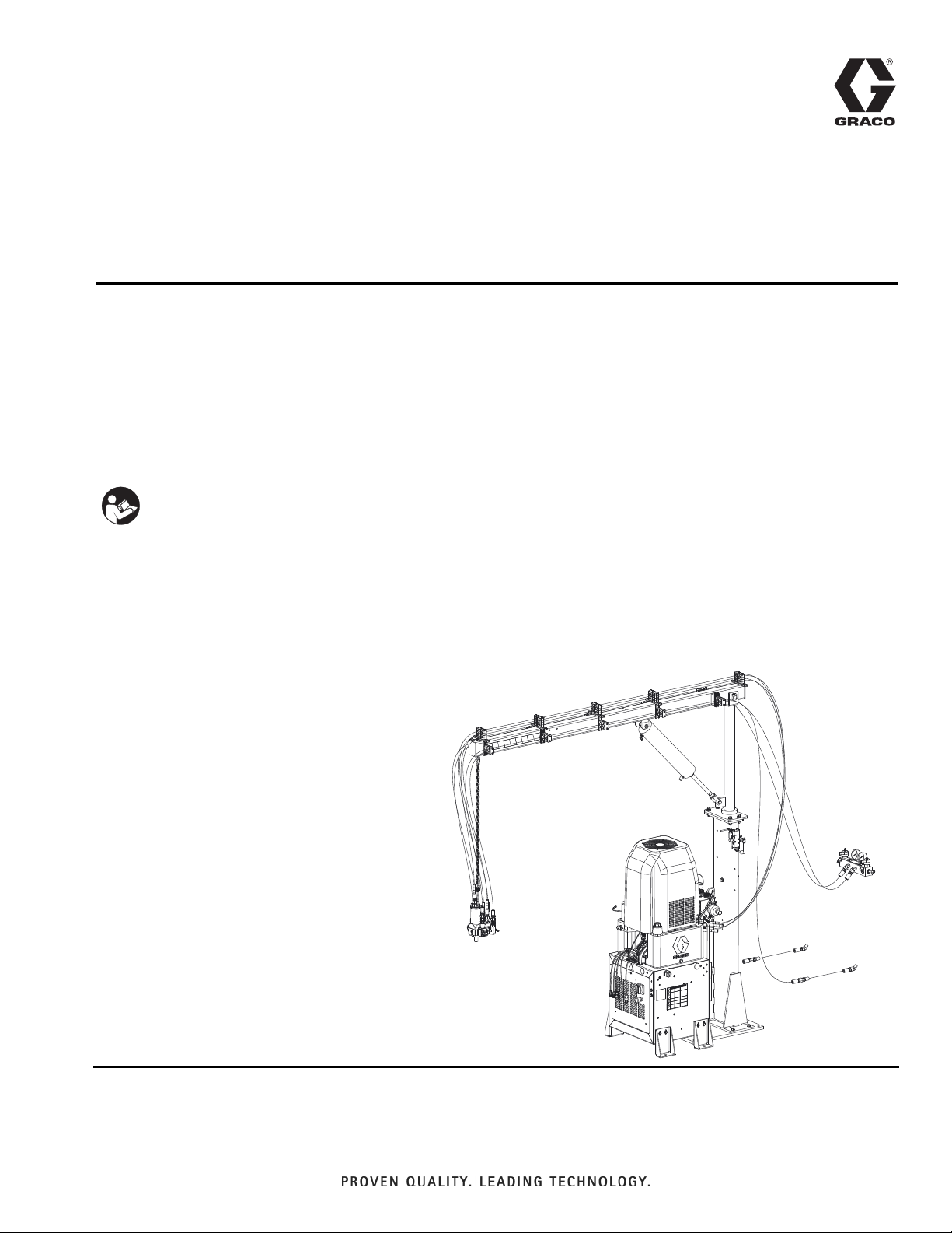
Instructions-Parts
AC Hydraulic
3A0238P
Power Pack Module
AC Hydraulic Power Pack, with optional boom and hose kits, for hydraulic actuated
applicators used with Graco HFR
For professional use only.
2500 psi (17 MPa, 172 bar) Maximum Hydraulic Working Pressure
Important Safety Instructions
Read all warnings and instr uctions in this
manual. Save these instructions.
™
and VRM™Metering Systems.
EN
See page 3 for model information.
24D829 AC Hydraulic Power Pack Module Shown
r_24d829_3A0238_1f
Page 2

Related Manuals
Contents
Related Manuals ...........................2
Models ...................................2
AC Hydraulic Power Pack Modules ........... 2
Applicator Kits ...........................3
Individual Applicators ..................... 3
Warnings .................................5
Isocyanate Conditions ..................... 8
Material Self-ignition ...................... 8
Keep Components A and B Separate .........8
Moisture Sensitivity of Isocyanates ...........8
Foam Resins with 245 fa Blowing Agents ......8
Changing Materials ....................... 9
Component Identification ................... 10
AC Power Pack Module ...................10
Hydraulic Power Pack Stand ............... 11
Main Power Disconnect ...................12
Circuit Breakers ......................... 12
Fluid Control Module (FCM) ...............13
Setup ....................................15
Connect Hydraulic Hoses .................15
Connect Material Hoses to System ..........18
Connect Communication Cables ............ 19
Connect Proximity Cables ................. 19
Connect Electrical Cord ..................20
Startup ..................................21
Operation ................................ 21
Pressure Relief Procedure ................ 21
Shutdown ................................ 21
Maintenance ..............................22
Schedule ..............................22
Troubleshooting ........................... 24
Repair ...................................27
Remove Hydraulic Power Pack Shroud .......27
Install Hydraulic Power Pack Shroud .........27
Remove Hydraulic Power Pack .............27
Install Hydraulic Power Pack ...............29
Replace Tank Gasket .....................29
Remove Motor ..........................30
Install Motor ............................31
Remove Hydraulic Gear Pump .............32
Install Hydraulic Gear Pump ...............33
Install FCM Upgrade Token ................34
Parts ....................................36
AC Hydraulic Power Pack Module ...........36
Mix Module Stand .......................38
Heat Exchanger Assembly ................40
230V and 400V MixHead Panel .............42
MixHead Hydraulic Power Pack .............44
Pneumatic Boom Arm ....................50
Hose Kits ..............................52
Hose and Cable Kits .......................54
Optional Equipment ........................55
Electrical Schematics ....................58
Dimensions ...............................66
AC Power Pack Module ...................66
AC Power Pack Stand ....................68
Pneumatic Boom ........................69
Technical Data ............................70
Graco Standard Warranty ...................72
Related Manuals
Manual Description
312753 L-Head, Operation-Maintenance
312752 S-Head, Operation-Maintenance
313536 GX-16, Operation
309582 Circulation and Return Tube Kits,
Instructions-Parts
313997 HFR, Operation
313998 HFR, Repair-Parts
2 3A0238P
Manual Description
313873 VRM, Operation
313874 VRM, Repair-Parts
3A0395 Stainless Steel Tank Stands, Instruc-
tions-Parts
3A0862 Hose Extension Kits, Instructions-Parts
Page 3

Models
Models
AC Hydraulic Power Pack Modules
The table below lists kit numbers for 230V and 400 VAC hydraulic power pack modules. The modules can come with
a hydraulic power pack, boom, and hose kits for S-Head and L-Head applicators. For applicator kits, see Applicator
Kits and Individual Applicators on page 4 (sold separately).
Includes: Not included
Hydraulic
S-Head
Kit No. Voltage
24D829
24D830
24D834✖
24D835✖
24D831
24D832
24D836✖
24D837✖
24F297★
24F298★✖
24J912★
24J913★✖
★ Purchase required hoses separately. See Hose and Cable Kits on page 54 for hose kits.
✖ See 400 V Power Requirements.
230V
230V
400V
400V
230V
230V
400V
400V
230V
400V
230V
400V
Boom
✔✔✔✔
✔✔ ✔ ✔
✔✔✔✔
✔✔ ✔ ✔
Hose Kits
✔✔ ✔
✔✔ ✔
L-Head
Hose Kits
✔✔ ✔
✔✔ ✔
Power
Pack
✔✔
✔✔
✔✔
✔✔
L-Head
Applicators
Only
400 V Power Requirements
S-Head
Applicators
Only
• 400 V systems are intended for International voltage
requirements. Not for voltage requirements in North
America.
• If a 400 volt configuration is operated in North America, a special transformer rated for 400 V (“Y” configuration (4 wire)) may be required.
• North America mostly employs a 3 wire or Delta
configuration. The two configurations are not interchangeable.
3A0238P 3
Page 4

Models
Applicator Kits
The table below lists S-Head and L-Head applicators kits. All applicator kits come with an injection nozzle and needle
valve calibration kit.
Maximum Working
Pressure
Applicator Kit No. Model
24A084 20.20.6/10 3000 (21, 206)
L-Head
S-Head
24A085 20.20.10/14 3000 (21, 206)
24A086 20.20.13/20 3000 (21, 206)
24A090 30100-500-4 3000 (21, 206)
24A092 30100-625-2 3000 (21, 206)
24A093 30110-625-4 3000 (21, 206)
psi (MPa, bar)
Individual Applicators
L-Head
The table below lists individual model numbers and chamber inside diameters. See L-Head manual for more information.
Maximum
Impingement
Chamber ID
Model
20.20.5/8 5 8 3000 (21, 206)
20.20.6/10 6 10 3000 (21, 206)
20.20.10/14 10 14 3000 (21, 206)
20.20.13/20 13 20 3000 (21, 206)
20.20.16/25 16 25 3000 (21, 206)
(mm)
S-Head
The table below lists individual model numbers and
stroke lengths. See S-Head manual for more information.
Maximum Working
Stroke
Model
30110-500-2 2.25 3000 (21, 206)
30100-500-4 4 3000 (21, 206)
30100-625-2 2.25 3000 (21, 206)
30110-625-4 4 3000 (21, 206)
(in.)
psi (MPa, bar)
Exiting Chamber
ID (mm)
GX-16
The table below lists individual model numbers. See
GX-16 manual for more information.
Pressure
Working
Pressure
psi (MPa, bar) CE Approved
✔
Applicator Model
GX-16
24E876
24E877
24E878
24J187
24K233
24K234
4 3A0238P
Page 5
Warnings
Warnings
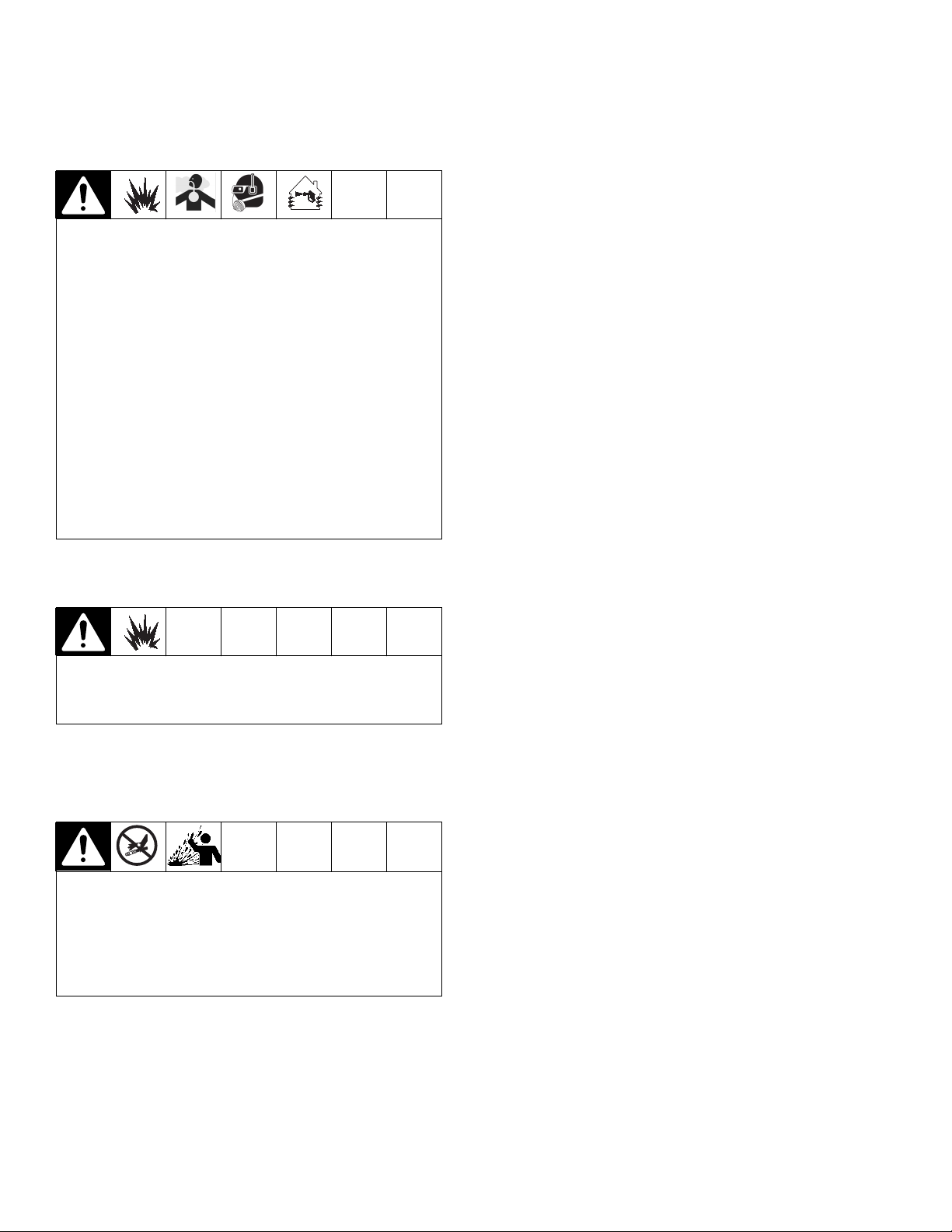
The following warnings are for the setup, use, grounding, maintenance, and repair of this equipment. The exclamation point symbol alerts you to a general warning and the hazard symbols refer to procedure-specific risks. When
these symbols appear in the body of this manual, refer back to these Warnings. Product-specific hazard symbols and
warnings not covered in this section may appear throughout the body of this manual where applicable.
DANGER
HIGH VOLTAGE ELECTRIC SHOCK HAZARD
This equipment uses high voltage power. Contact with high voltage equipment and improper grounding,
setup, or usage of the system can cause death or serious injury.
• Turn off and disconnect power at main switch before disconnecting any cables and before servicing
equipment.
• This equipment must be grounded. Connect only to grounded power source.
• All electrical wiring must be done by a qualified electrician and comply with all local codes and regulations.
WARNING
WARNINGWARNINGWARNING
TOXIC FLUID OR FUMES HAZARD
Toxic fluids or fumes can cause serious injur y or death if splashed in the eyes or on skin, inhaled, or swal-
lowed.
• Read MSDSs to know the specific hazards of the fluids you are using.
• Store hazardous fluid in approved containers, and dispose of it according to applicable guidelines.
• Always wear chemically impermeable gloves when spraying, dispensing, or cleaning equipment.
PERSONAL PROTECTIVE EQUIPMENT
You must wear appropriate protective equipment when operating, ser vicing, or when in the operating area
of the equipment to help protect you from serious injury, including eye injury, hearing loss, inhalation of
toxic fumes, and burns. This equipment includes but is not limited to:
• Protective eyewear, and hearing protection.
• Respirators, protective clothing, and gloves as recommended by the fluid and solvent manufacturer.
3A0238P 5
Page 6
Warnings
WARNING
WARNINGWARNINGWARNING
SKIN INJECTION HAZARD
High-pressure fluid from dispensing device, hose leaks, or ruptured components will pierce skin. This may
look like just a cut, but it is a serious injury that can result in amputation. Get immediate surgical treat-
ment.
• Engage trigger lock when not dispensing.
• Do not point dispensing device at anyone or at any part of the body.
• Do not put your hand over the fluid outlet.
• Do not stop or deflect leaks with your hand, body, glove, or rag.
• Follow the Pressure Relief Procedure when you stop dispensing and before cleaning, checking, or
servicing equipment.
• Tighten all fluid connections before operating the equipment.
• Check hoses and couplings daily. Replace worn or damaged parts immediately.
PRESSURIZED EQUIPMENT HAZARD
Fluid from the gun/dispense valve, leaks, or ruptured components can splash in the eyes or on skin and
cause serious injury.
• Follow the Pressure Relief Procedure when you stop spraying and before cleaning, checking, or servicing equipment.
• Tighten all fluid connections before operating the equipment.
• Check hoses, tubes, and couplings daily. Replace worn or damaged parts immediately.
FIRE AND EXPLOSION HAZARD
Flammable fumes, such as solvent and paint fumes, in work area can ignite or explode. To help prevent
fire and explosion:
• Use equipment only in well ventilated area.
• Eliminate all ignition sources; such as pilot lights, cigarettes, portable electric lamps, and plastic drop
cloths (potential static arc).
• Keep work area free of debris, including solvent, rags and gasoline.
• Do not plug or unplug power cords, or turn power or light switches on or off when flammable fumes
are present.
• Ground all equipment in the work area. See Grounding instructions.
• Use only grounded hoses.
• Hold gun firmly to side of grounded pail when triggering into pail.
• If there is static sparking or you feel a shock, stop operation immediately. Do not use equipment
until you identify and correct the problem.
• Keep a working fire extinguisher in the work area.
6 3A0238P
Page 7
Warnings
WARNING
WARNINGWARNINGWARNING
PRESSURIZED ALUMINUM PARTS HAZARD
Use of fluids that are incompatible with aluminum in pressurized equipment can cause serious chemical
reaction and equipment rupture. Failure to follow this warning can result in death, serious injury, or property damage.
• Do not use 1,1,1-trichloroethane, methylene chloride, other halogenated hydrocarbon solvents or fluids containing such solvents.
• Many other fluids may contain chemicals that can react with aluminum. Contact your material supplier
for compatibility.
EQUIPMENT MISUSE HAZARD
Misuse can cause death or serious injury.
• Do not operate the unit when fatigued or under the influence of drugs or alcohol.
• Do not exceed the maximum working pressure or temperature rating of the lowest rated system component. See Technical Data in all equipment manuals.
• Use fluids and solvents that are compatible with equipment wetted parts. See Technical Data in all
equipment manuals. Read fluid and solvent manufacturer’s warnings. For complete information about
your material, request MSDS from distributor or retailer.
• Do not leave the work area while equipment is energized or under pressure. Turn off all equipment
and follow the Pressure Relief Procedure when equipment is not in use.
• Check equipment daily. Repair or replace worn or damaged parts immediately with genuine manufacturer’s replacement parts only.
• Do not alter or modify equipment.
• Use equipment only for its intended purpose. Call your distr ibutor for information.
• Route hoses and cables away from traffic areas, sharp edges, moving parts, and hot surfaces.
• Do not kink or over bend hoses or use hoses to pull equipment.
• Keep children and animals away from work area.
• Comply with all applicable safety regulations.
MOVING PARTS HAZARD
Moving parts can pinch, cut or amputate fingers and other body parts.
• Keep clear of moving parts.
• Do not operate equipment with protective guards or covers removed.Pressurized equipment can start
without war ning. Before checking, moving, or servicing equipment, follow the Pressure Relief Proce-
dure and disconnect all power sources.
BURN HAZARD
Equipment surfaces and fluid that’s heated can become very hot during operation. To avoid severe burns:
• Do not touch hot fluid or equipment.
3A0238P 7
Page 8
Warnings
Isocyanate Conditions
Spraying or dispensing materials containing isocyanates creates potentially harmful mists, vapors, and
atomized particulates.
Read material manufacturer’s warnings and material
MSDS to know specific hazards and precautions
related to isocyanates.
Prevent inhalation of isocyanate mists, vapors, and
atomized particulates by providing sufficient ventilation in the work area. If sufficient ventilation is not
available, a supplied-air respirator is required for
everyone in the work area.
To prevent contact with isocyanates, appropriate personal protective equipment, including chemically
impermeable gloves, boots, aprons, and goggles, is
also required for everyone in the work area.
Material Self-ignition
Some materials may become self-igniting if applied
too thickly. Read material manufacturer’s warnings
and material MSDS.
Keep Components A and B
Moisture Sensitivity of Isocyanates
Isocyanates (ISO) are catalysts used in two component
foam and polyurea coatings. ISO will react with moisture
(such as humidity) to form small, hard, abrasive crystals,
which become suspended in the fluid. Eventually a film
will form on the surface and the ISO will begin to gel,
increasing in viscosity. If used, this partially cured ISO
will reduce performance and the life of all wetted parts.
NOTE: The amount of film formation and rate of crystallization varies depending on the blend of ISO, the
humidity, and the temperature.
To prevent exposing ISO to moisture:
• Always use a sealed container with a desiccant
dryer in the vent, or a nitrogen atmosphere. Never
store ISO in an open container.
• Keep the ISO lube pump reservoir (if installed) filled
with Graco Throat Seal Liquid™(TSL™), Part
206995. The lubricant creates a barrier between the
ISO and the atmosphere.
• Use moisture-proof hoses specifically designed for
ISO, such as those supplied with your system.
• Never use reclaimed solvents, which may contain
moisture. Always keep solvent containers closed
when not in use.
• Never use solvent on one side if it has been contaminated from the other side.
• Always lubricate threaded parts with ISO pump oil
or grease when reassembling.
Separate
Foam Resins with 245 fa Blowing Agents
Some foam blowing agents will froth at temperatures
Cross-contamination can result in cured material in
fluid lines which could cause serious injury or damage equipment. To prevent cross-contamination of
the equipment’s wetted parts, never interchange
component A (isocyanate) and component B (resin)
parts.
8 3A0238P
above 90°F (33°C) when not under pressure, especially
if agitated. To reduce frothing, minimize preheating in a
circulation system.
Page 9

Changing Materials
• When changing materials, flush the equipment multiple times to ensure it is thoroughly clean.
• Always clean the fluid inlet strainers after flushing.
• Check with your material manufacturer for chemical
compatibility.
• Most materials use ISO on the A side, but some use
ISO on the B side.
• Epoxies often have amines on the B (hardener)
side. Polyureas often have amines on the B (resin)
side.
Warnings
3A0238P 9
Page 10
Component Identification
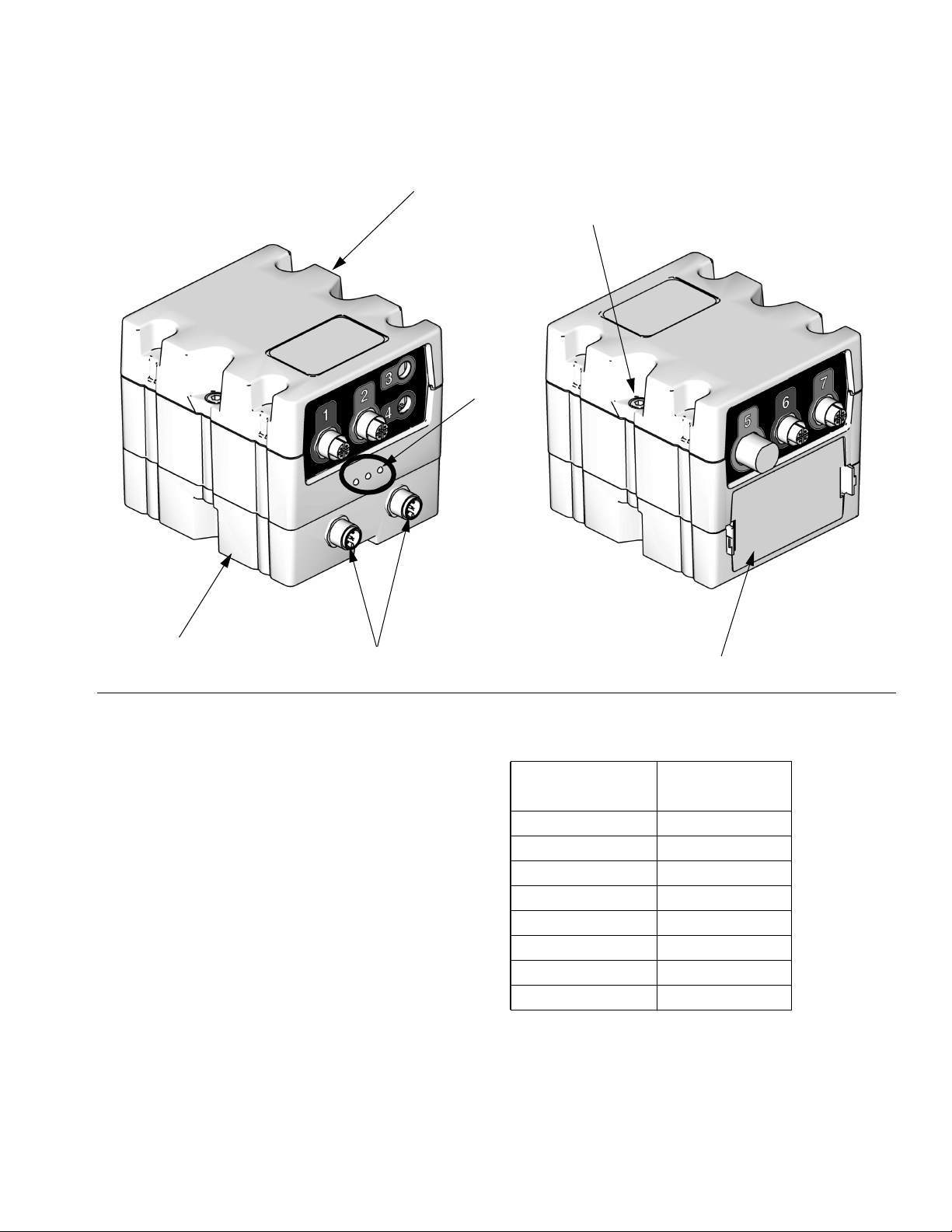
Component Identification
AC Power Pack Module
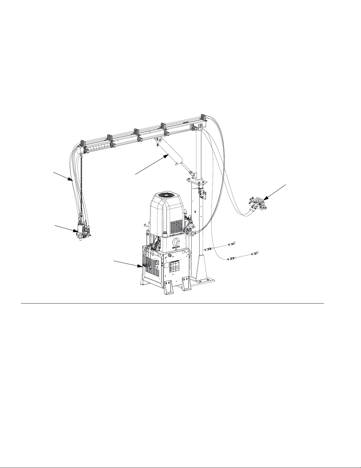
24D829 AC Power Pack Module shown with circulation lines
B
D
A
FIG. 1: Typical Installation
Key:
A AC Hydraulic Power Pack
B Hose Kit (includes A, B, and hydraulic hoses)
C Boom (not included with all power pack kits)
D Applicator (not included)
E GMS
™
Fluid Manifold (not included)
C
E
r_24d829_3A0238_1f
10 3A0238P
Page 11
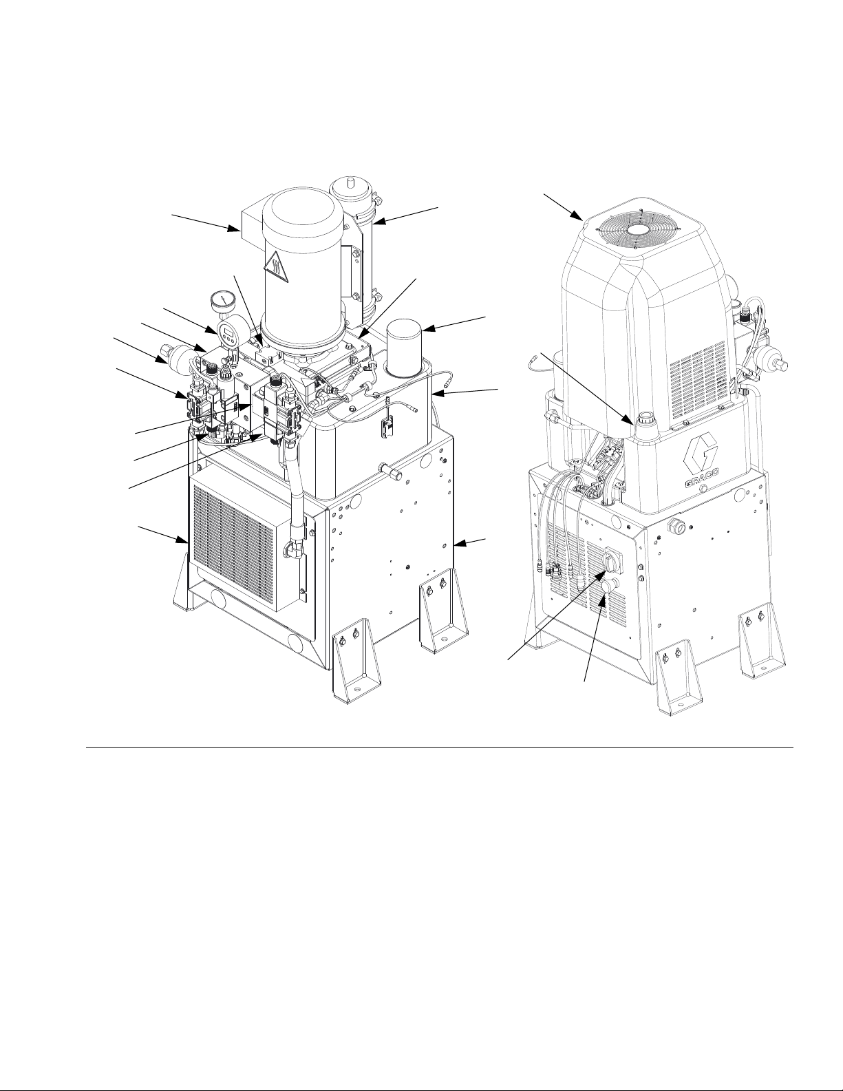
Hydraulic Power Pack Stand
AB
Component Identification
AG
AH
AM
AW
AJ
AX
AL
AK
AE, AS
AV
AN
AD
AF
AC
AA
AU
AP
AT
r_24C065_3a0238_1d
r_24C065_3a0238_11e
FIG.2
Key:
AA 10 Gallon Hydraulic Oil Reservoir (see Technical Data on
page 70 for specifications)
AB Electric Motor
AC Dipstick
AD Hydraulic Housing
AE Heat Exchanger
AF Filter
AG Shroud
AH Mixhead Accumulator - 1200 psi (24.1 MPa, 241 bar) pre-
charge
AJ Cleanout Directional Valve
AK Accumulator Directional Valve
AL Dispense Directional Valve
AM Applicator Adapter Housing
AN Diverter Block
3A0238P 11
AP Main Power Disconnect
AR Electronics Panel (inside stand)
AS Heat Exchanger Cover
AT Cycle Stop Button
AU Stand
AV Hydraulic Pressure Gauge
AW Return Accumulator - 150 psi (1.0 MPa, 10 bar) precharge
AX Check Valve
Page 12
Component Identification
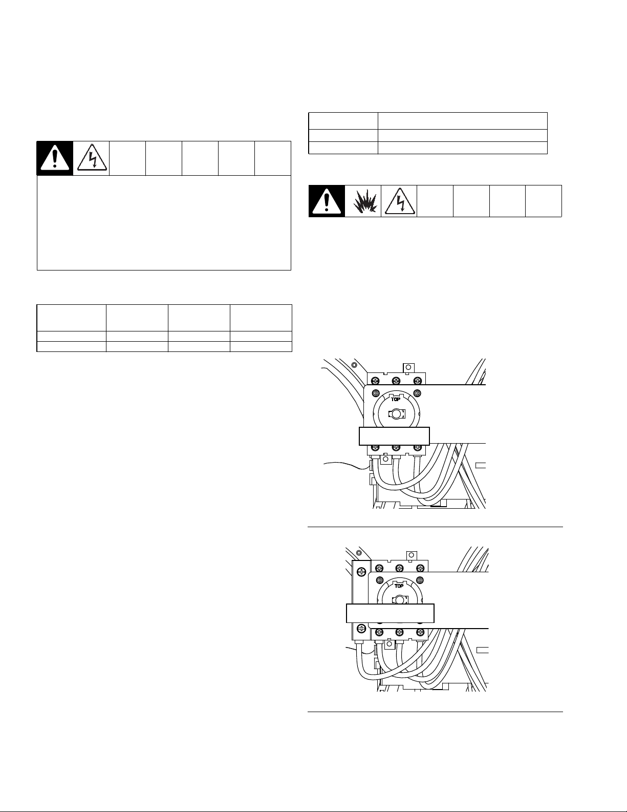
Main Power Disconnect
Below are the on and off positions for the main power
disconnect (AP) located on the AC Power Pack module.
NOTE: The power must be turned “On” at the GMS
unit first.
On position
r_121148_3a0238_1a r_121148_3a0238_2a
FIG. 3: Main Power Disconnect
Off Position
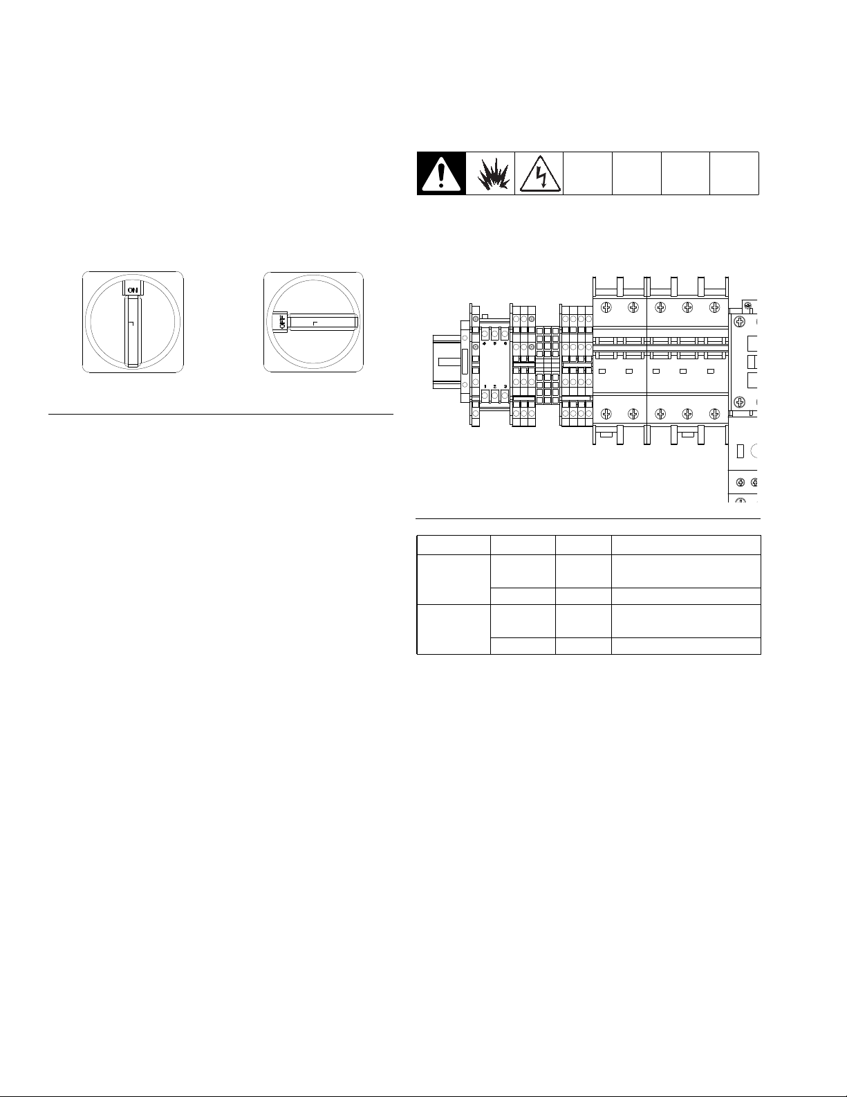
Circuit Breakers
Circuit breakers are located inside the power pack frame
stand.
CB125CB113
r_24d427_3a0238_1c
FIG. 4: Circuit Breakers
Model Ref. No. Size Component
230V CB125 30 A Directional Valve and
heat exchanger fan
CB113 5 A Motor
400V CB125 20 A Directional valve and
heat exchanger fan
CB113 5 A Motor
12 3A0238P
Page 13
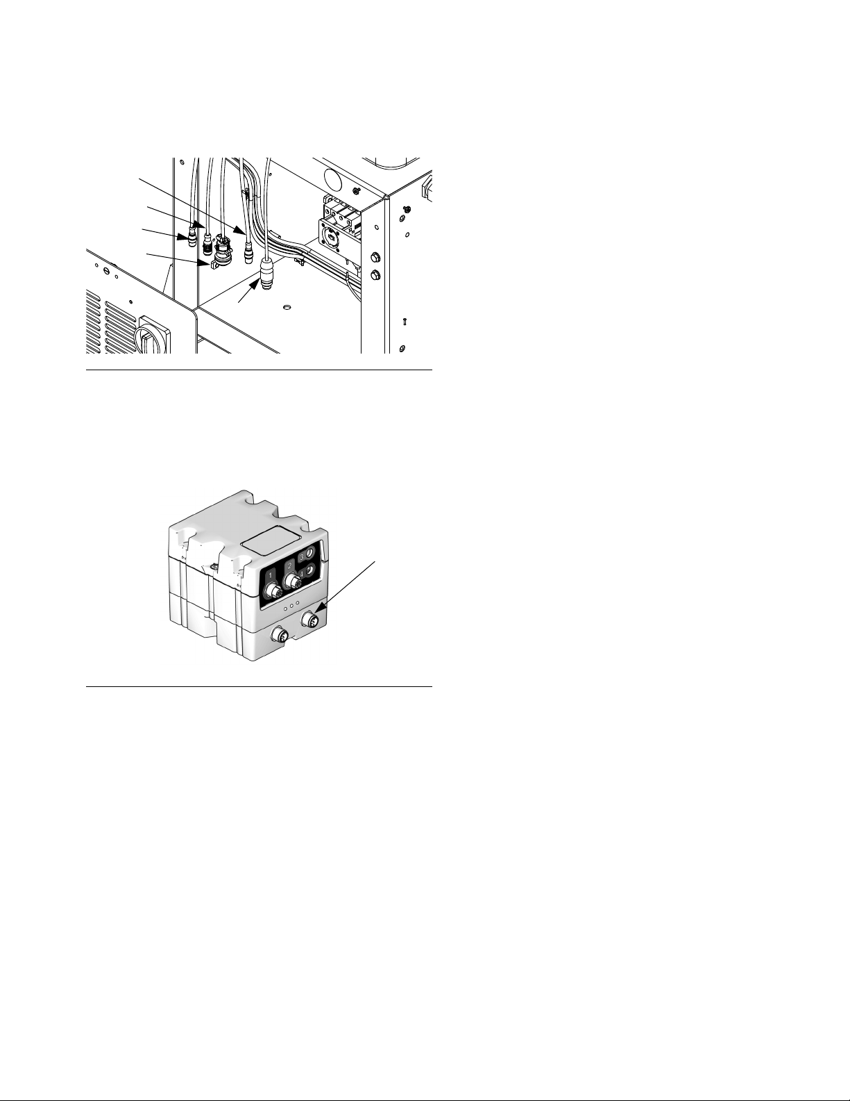
Fluid Control Module (FCM)
Component Identification
BA
BC
BE
BB
FIG.5
Key:
BA Fluid Control Module
BB Base
BC Module Connection Screws
BD Access Cover
BE Module Status LEDs
BF CAN Connectors
BF
TI12337A
TI12336A
BD
FCM Cable Connections
FCM
Connections Cable
1 123673
2 123673
3 121686
4 121686
5 24E052
6 122497
CAN connector 1 123762
CAN connector 2 123856
3A0238P 13
Page 14

Component Identification
Diagnostic Information
7
Module Status LED Signal Diagnosis Solution
Green on System is powered up -
Yellow Internal communication in progress -
Red solid FCM hardware failure Replace FCM
Red flashing fast Uploading software -
Red flashing slow Token error Remove token and upload software
token again.
Adjust Selector Switch
The fluid control module uses a 16-position selector
switch. Set selector switch (S) to specific selection
according to the settings listed in the following table.
Setting 1 is the only valid position.
Selector Switch Settings
Setting Zone
00
11
22
33
44
55
66
77
88
99
AA
BB
CC
DD
EE
FF
14 3A0238P
Page 15

Setup
Avoid breathing of vapors and contact with Isocyante
as some people have severe allergic reactions. See
Isocyanate Conditions on page 8.
Avoid routing hoses in walkway areas to prevent
operators from tripping on hoses running between
system components.
1. Anchor the stand to the floor (mounting hardware
not included). See Dimensions on starting on page
66 for mounting dimensions. Suggested anchors:
McMaster-Carr (part no. 92403A400).
NOTE: The AC power pack (A) needs to be mounted
no more than 6 ft (1.8m) away from the front of the
GMS unit.
2. If the AC power pack has a boom (C), anchor the
boom to the floor (mounting hardware not included).
See Dimensions on starting on page 66 for mounting dimensions. Suggested anchors: McMaster-Carr
(part no. 92403A400).
Setup
Connect Hydraulic Hoses
Hydraulic lines could rupture and cause injury. Use
hydraulic hoses with a pressure rating higher than
what the system is set to.
Twisted hydraulic hoses can cause the hoses to
fatigue sooner and rupture. Ensure that the hydraulic
hoses do not twist between the AC power pack and
the applicator.
NOTICE
Damage can occur to the directional valve if the
hydraulic hose diameter is larger than 3/8 in. (9.5
mm).
To prevent damage to the applicator or directional
valves, do not allow any dirt or foreign matter to
enter the lines, when connecting the hose kit (B) to
the applicator (D) and hydraulic power pack (A).
NOTE:
• If your AC Power Pack Module has a boom (C),
the AC Power Pack (A) needs to be installed
within 12 in. (304.8 mm) of the boom and the
boom needs to be installed within 3 ft (1 m) of
the GMS unit.
• Ensure that the hose connections for applicator
(D) face the mast. See FIG.1onpage10.
3. If the AC power pack has a boom (C), mount the
applicator (D) to the boom (C). Complete Installa-
tion instructions in the applicator manual.
Connect Hydraulic Hoses to Power Pack
1. Connect L-Head hydraulic hoses:
a. Connect the hydraulic hose fittings (A1, A2, B1,
and B2) on the AC power pack to the ends of
hydraulic hose (401) on the mast side of the
boom (C) as listed in the table below. See FIG.
1, page 10 and FIG. 6, page 16.
2. Connect S-Head and GX-16 hydraulic hoses:
a. Connect the hydraulic hose fittings (A2 and B2)
on the AC power pack to the ends of hydraulic
hose (402) on the mast side of the boom (C) as
listed in the table below. See FIG. 1, page 10
and FIG . 6, page 16.
b. Use caps (6) to plug A1 and B1 fittings.
3A0238P 15
Page 16
Setup
Hydraulic
Hose Fitting
Hydraulic
Hoses
Hydraulic Hose
Color Markings
A1✖ Cleanout close Green/Green
A2 Material close Green
B1✖ Cleanout open Green/White/Green
B2 Material open Green/White
✖ Not used for S-Head and GX-16 applicators.
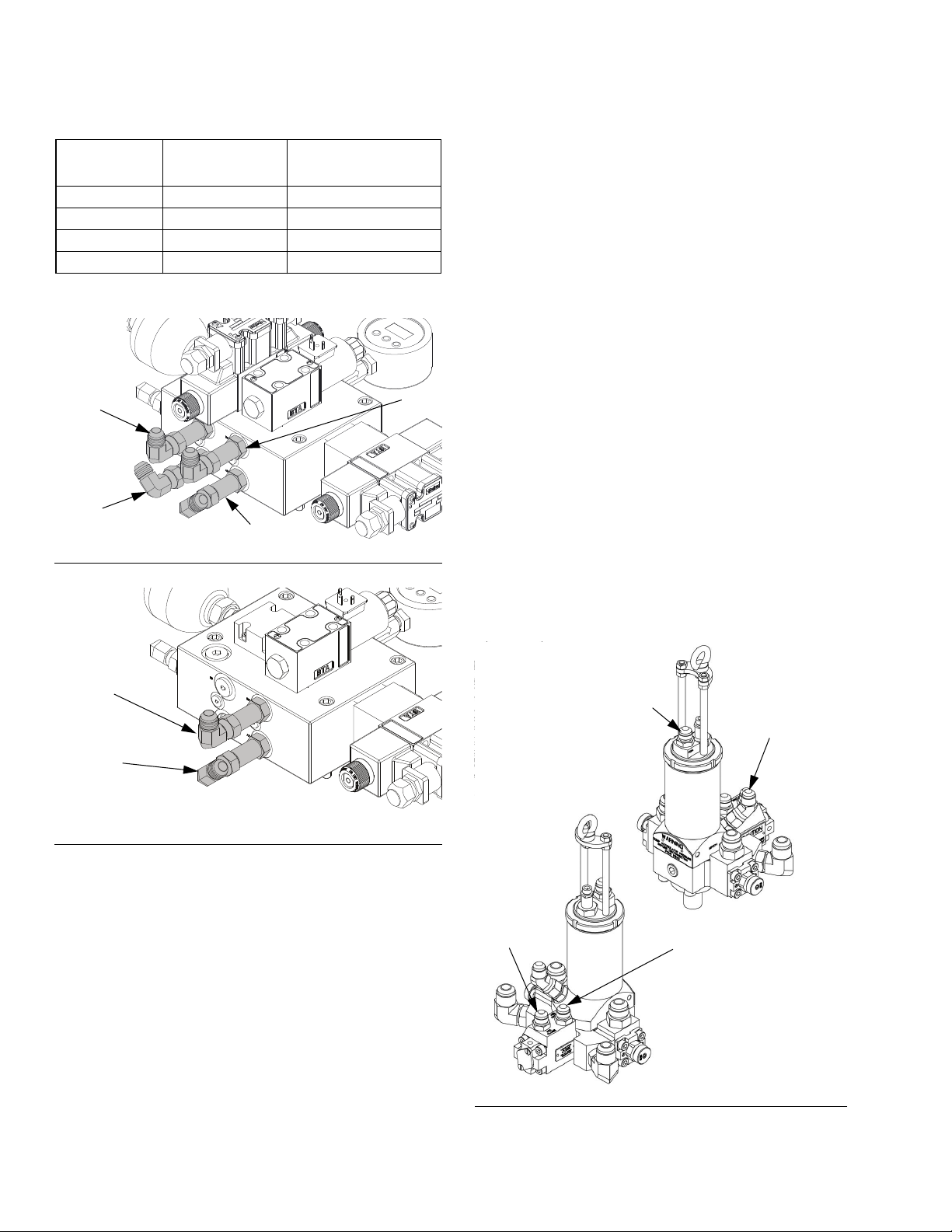
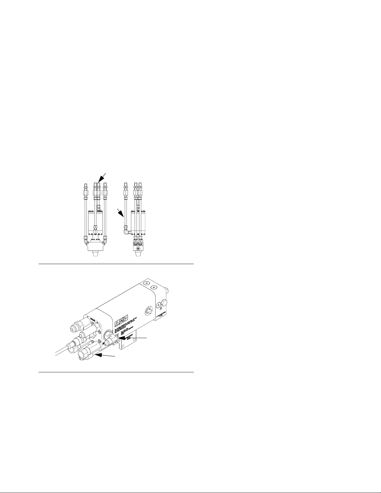
Connect Hydraulic Hoses to Applicator
If the AC power pack (A) has a boom (C), these connections will be hanging off the end of the boom.
L-Head
See FIG .8.
1. Connect the A1 hose, with green/green markings, to
the cleanout close port (CC) on the applicator.
2. Connect the A2 hose, with the green markings, to
the material close port (MC) on the applicator.
B1
A1
A2
FIG. 6: L-Head Applicator Hydraulic Housing
B2
A2
FIG. 7: S-Head Applicator Hydraulic Housing
B2
ti17743a
3. Connect the B1 hose, with the green/white/green
markings, to the cleanout open port (CO) on the
applicator.
4. Connect the B2 hose, with the green/white markings, to the material open (MO) port on applicator.
5. Hand tighten each fitting.
6. Bleed air from the hydraulic fluid lines. See the
applicator manual for instructions.
7. Tighten each fitting 1-1/2 flats past hand tight.
CC
CO
3. Hand tighten each fitting.
4. Tighten each fitting 1-1/2 flats past hand tight.
MC
MO
FIG. 8: Hydraulic connections on L-Head
16 3A0238P
Page 17
S-Head and GX-16
See FIG . 9 and FIG. 10.
1. Connect the B2 hose, with green/white markings, to
the hydraulic open (HO) port fitting.
2. Connect the A2 hose, with green markings, to the
hydraulic close (HC) port fitting.
3. Hand tighten each fitting.
4. Bleed air from the hydraulic fluid lines. See the
applicator manual for instructions.
5. Tighten each fitting 1-1/2 flats past hand tight.
Setup
TOP
HC
RIGHT
HO
FIG. 9: Hydraulic connections on S-Head
HC
HO
ti17747a
FIG. 10: Hydraulic connections on GX-16
3A0238P 17
Page 18
Setup
Connect Material Hoses to System
For System With Circulation
NOTICE
Avoid routing hoses in walkway areas to prevent
operators from tripping on hoses running between
system components. This also prevents fittings from
leaking.
1. Connect the A (red) and B (blue) supply hoses, from
hose kit (3), to the GMS material manifold. See FIG.
11.
2. Connect the other end of the supply hoses to the
applicator. See the applicator manual for fluid inlet
identification.
A
GMS material
manifold
3
421
422
B
fluid inlet
fitting
FIG. 12: Tank Stand Connections
5. Tighten each fitting.
r_257968_3a0238_1c
For System Without Circulation
NOTICE
Avoid routing hoses in walkway areas to prevent
operators from tripping on hoses running between
system components. This also prevents fittings from
leaking.
1. Connect the A (red) and B (blue) supply hoses, from
hose kit (3), to the GMS material manifold. See FIG.
11.
2. Connect the other end of the supply hoses to the
applicator. See the applicator manual for fluid inlet
identification.
3. Hand tighten each fitting.
4. Tighten each fittings 1-1/2 flats past hand tight.
FIG.11
NOTE: The circulation hoses contain a 10 ft (3 m)
extension hose to reach the tank stands.
3. Connect the other end of the A (red) circulation
hose (421) to the fluid inlet fitting on the A (red) tank
stand. See FIG. 11 and FIG. 12.
4. Connect the other end of the B (blue) circulation
hose (422) to the fluid inlet fitting on the B (blue)
tank stand.
18 3A0238P
Page 19
Setup
Connect Communication Cables
83
121
84
122
123
FIG.13
1. Feed end of communication cable (83) through bulkhead of the HFR base unit.
2. Connect communication cable (83) to any open
CAN connector of a GCA cube.
5. Connect the termination connector (425) to the connector (121), labeled 5A. Feed the connector (425)
and cables (121, 84) into the base cube and secure.
S-Head (Includes GX-16)
1. Connect control cable (84) to the motor control module splitter labeled “2A” found on the HFR unit.
Refer to the HFR manual for detailed locations
2. Connect the S-head proximity sensor to the electrical connector found within the material hose bundle.
3. Connect the other end of the cord to the electrical
connector found near the fluid manifold on the HFR.
4. Feed the cables (121, 122, 123) into the base cube
and secure.
TI12337A
FIG.14
Connect Proximity Cables
L-Head
1. Connect the applicator end of the proximity sensor
cable (418) to the dispense proximity sensor on the
L-Head.
2. Connect the applicator end of the proximity sensor
cable (419) to the cleanout proximity sensor on the
L-Head.
3. Connect the other end of the proximity sensor cable
(418) to the dispense proximity sensor cable (122),
labeled A1, on the AC power pack. See FIG. 13.
4. Connect the other end of the proximity sensor cable
(419) to the cleanout proximity sensor pigtail (123),
labeled 2C, on the AC power pack. See FIG. 13.
3A0238P 19
Page 20
Setup
Connect Electrical Cord
Electrical Requirements. See Table 1.
Installing this equipment requires access to parts
which may cause electric shock or other serious
injury if work is not performed properly. Have a qualified electrician connect power and ground to main
power switch terminals, see FIG. 15. Be sure your
installation complies with all National, State, and
Local safety and fire codes.
Table 1: Electrical Requirements
(kW/Full Load Amps)
Voltage
Model
230V 230V (3) 17 4000
400V✖ 400V (3) 18 3200
* Full load amps with all devices operating at maximum
capabilities. Fuse requirements at various flow rates and
mix chamber sizes may be less.
(phase)
Full Load
Peak Amps*
System
Watts
NOTE: Power cord is not supplied. See Table 2.
Table 2: Power Cord Requirements
Model Cord Requirements AWG (mm2)
230V 10 (5.3), 3 wire
400V 10 (5.3), 4 wire
✖ See 400 V Power Requirements, page 3.
Electrical Cord Wires by Model
230V, 3 phase: L1, L2, L3
400V, 3 phase ✖ : L1, L2, L3, N
✖ See 400 V Power Requirements, page 3.
Use 5/32 or 4 mm hex allen wrench to connect three
power leads to L1, L2, and L3.
✖ See 400 V Power Requirements, page 3.
L3
L2
L1
FIG. 15: 230V, 3 phase shown
L3
L2
L1
N
FIG. 16: 400V, 3 phase shown
20 3A0238P
Page 21
Startup
Startup
The hydraulic power pack operates at a high pres-
sure and high voltage. Be careful during operation
and always wear the appropriate protective gear.
1. Ensure all hydraulic connections are tight.
2. Turn on main power to power pack.
3. Turn power switch to the ON position.
4. Set system settings in ADM. See system operation
manual for instructions.
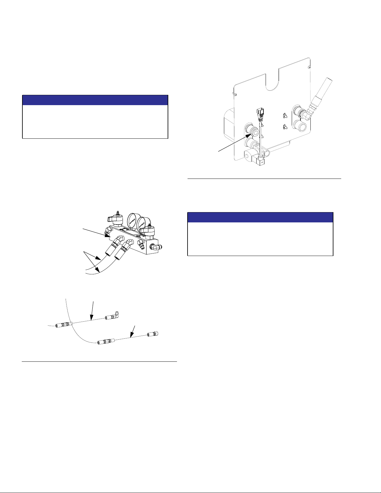
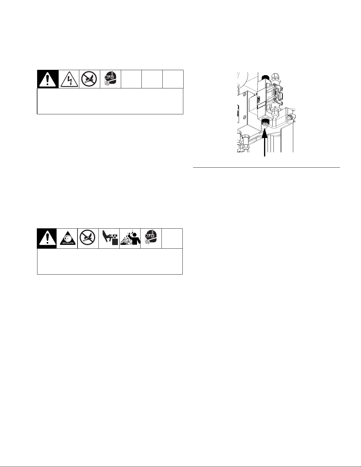
Operation
Pressure Relief Procedure
3. Press in the lower solenoid of the accumulator
charging directional valve.
FIG.17
4. Ensure that the pressure gauge is zero psi.
5. To relieve pressure in material hoses, perform Pres-
sure Relief Procedure in HFR manual 313997.
Shutdown
Trapped air can cause the pump to cycle unexpect-
edly, which could result in serious injury from splashing or moving parts.
Always relieve hydraulic pressure of AC power pack:
• Before performing system maintenance
• Long term (over night) shutdown
1. Shutdown the power pack. See Shutdown.
2. Open the needle valve to show the pressure on the
gauge.
NOTE: Ensure that the motor is not running.
1. Shutdown HFR.
2. Turn main power switch to the OFF position.
3. Turn off and lock out main power.
3A0238P 21
Page 22

Maintenance
Maintenance
Check the Accumulator Pre-Charge
Graco Charging Harness (part no. 124217) can be purchased to aid in quick charging of the accumulator.
Schedule
Procedure Frequency
Check Accumulator Pre-Charge Weekly
Check Tightness of all Clamps and
Fittings
Check Hoses for Wear Monthly
Check Hydraulic Fluid and Filter 6 months
NOTICE
Recommended Hydraulic Oil
Use Graco-approved Hydraulic Oil, Part No. 169236
(5 gal) or 207428 (1 gal)) or a premium, ISO grade
46 petroleum-based hydraulic oil containing rust
and oxidation inhibitors and anti-wear agents.
Before using any other type of oil in this motor, contact your Graco distributor. Unauthorized use of
lesser grade oil or substitutes may void the warranty.
Hydraulic Oil Working Temperature
The maximum hydraulic oil operating temperature is
180 °F (82 °C). The motor seals will wear faster and
leakage may occur if the pump is operated at higher
oil temperatures.
If the hydraulic oil temperature approaches 180 °F
(82 °C), check the hydraulic fluid supply cooling system, filters, etc. and clean or repair as needed.
Keep the hydraulic system clean
To reduce the risk of damaging the hydraulic driver,
verify that the hydraulic power supply fluid lines and
reservoir are clean and free from contaminants.
Carefully follow the manufacturer’s recommendations on reservoir and filter cleaning, flushing, and
periodic changes of hydraulic fluid.
Weekly
1. Turn off main power and lockout.
2. Bleed the accumulator charging valve hydraulic
pressure to zero. See Pressure Relief Procedure,
page 21.
3. Connect the charging harness to the accumulator.
4. Check the reading on the nitrogen harness pressure
gauge. If the pressure is below 1200 psi, then
Pre-Charge the Accumulator to 1200 psi.
5. Repeat the procedure for the return accumulator
(AW, FIG. 2) with the precharge set to 150 psi
(1.0 MPa, 10 bar).
Pre-Charge the Accumulator
NOTICE
During this procedure the nitrogen bottle, the accumulator, and the charging harness will all be under
significant pressure. Use dry nitrogen gas only.
1. Check the Accumulator Pre-Charge.
2. Connect the other end of the harness to the nitrogen
bottle. Slowly open the nitrogen bottle valve while
observing the pressure gauge.
3. When the1200 psi is reached, close the nitrogen
valve.
4. Open the bleed valve on the charging harness to
relieve residual pressure in the charging harness.
5. Remove the charging harness and replace the bottle guard.
6. Repeat the procedure for the return accumulator
(AW, FIG. 2) with the precharge set to 150 psi
(1.0 MPa, 10 bar).
Always plug the hydraulic inlets, outlets and lines
when disconnecting them to avoid introducing dirt
and other contaminants into the system.
22 3A0238P
Page 23

Maintenance
Check Hydraulic Fluid
NOTE: Standard temperature switch cuts out at a
housing temperature of 160°F (71°C) and approximately 180°F (82°C) hydraulic fluid temperature.
Check Hydraulic Fluid Level
1. Remove the breather filler cap (246).
2. If the fluid level is between the high and low tick
marks, the fluid level is correct.
3. If the fluid level falls below the low fluid level tick
mark, add fluid until the level is between the high
and low level tick marks.
246
high fluid level
6. To add clean hydraulic fluid see Check Hydraulic
Fluid Level.
87
FIG. 19: Drain Cap
Replace Hydraulic Filter
NOTICE
Be careful not to allow any debris into the hydraulic
tank when replacing the filter. If any debris falls into
the hydraulic tank, the debris must be removed or
machine damage will result.
1. Shutdown the system. See Shutdown on page 21.
low fluid level
FIG. 18: High and Low Fluid Level Marks
Check Condition of Hydraulic Fluid
1. Remove the breather filler cap (246).
2. Remove some of the hydraulic fluid.
3. Replace the fluid if the fluid becomes cloudy.
Replace Hydraulic Fluid
Use only recommended hydraulic fluids. See FIG. 19.
NOTE: Be prepared to collect 10 gallons (38 liters) of
fluid when emptying the tank.
1. Shutdown the system. See Shutdown on page 21.
2. Relieve Pressure. See Pressure Relief Procedure
on page 21.
3. Place a container below drain port.
2. Relieve Pressure. See Pressure Relief Procedure
on page 21.
3. Use compressed air to remove any loose debris
around the hydraulic filter (245).
4. Apply a light coat of hydraulic fluid to the sealing
surface of the new hydraulic filter (245).
5. Replace the old filter with the new filter (245).
6. Start system.
7. Check for any leaks.
245
4. Remove drain cap (87) from the side of the hydraulic
reservoir and drain the reservoir.
5. Install drain cap (87).
3A0238P 23
FIG. 20: Hydraulic Fluid Filter
Page 24

Troubleshooting
Troubleshooting
Problem Cause Solution
Pressure gauge drops to zero while
in operation.
No hydraulic pressure. Motor is not turning. Ensure main power is ON.
Accumulator precharge is too high. Ensure accumulator precharge is
no more than 1200 psi.
Ensure all electrical connections to
the motor are secure.
Check motor circuit breaker to see if
it has been tripped. Ensure all
cables are connected to FCM connectors.
Replace motor. See page 30.
Ensure all cables are connected to
FCM connectors. See FCM Cable
Connections, page 13.
Motor is spinning clockwise. Switch two phases of incoming
power.
Leaking fluid from fittings. Tighten leaking fittings.
Accumulator directional valve is not
charging.
Ensure accumulator charging directional valve is shifting. Verify LED
lights turn ON and OFF.
Check circuit breaker to see if it has
been tripped.
Replace directional valve. See page
27.
Replace accumulator.
Ensure all cables are connected to
FCM connectors. See FCM Cable
Connections, page 13.
Low hydraulic fluid level in oil reservoir.
Leaking hydraulic fluid around the
hydraulic filter.
24 3A0238P
Damaged or clogged filter. Replace hydraulic filter. See page
Check hydraulic fluid level. Refill as
necessary.
27.
Page 25

Troubleshooting
Problem Cause Solution
Hydraulic fluid over heating. Fan in base cube is not spinning. Check electrical connections to fan.
Replace fan.
Material is not dispensing from
applicator.
Hydraulic fluid leaking around any
directional valves.
Hydraulic fluid leaking around
diverter block.
Heat exchanger in base cube is
Replace.
clogged or leaking.
Low hydraulic fluid level in oil reservoir.
Check hydraulic fluid level. Refill as
necessary.
Cycle rate too fast. Increase time between shots.
Damaged gear pump. Replace gear pump. See page 32.
Damaged coupler between motor
and gear pump.
Visually inspect coupler and spider
coupling between motor and gear
pump. Replace if necessary.
Material hoses are not connected. Check material hoses for damage
or leaking fittings.
Ensure material hoses are connected properly. See Setup on
page 15.
Damaged or worn o-ring. Replace o-ring. Clean o-ring sur-
faces and grooves prior to replacement.
Damaged or worn o-ring. Replace o-ring. Clean o-ring sur-
faces and grooves prior to replacement.
Applicator not cycling.
(continued on the next page)
No hydraulic pressure. See page 24 for possible causes
and solutions.
Leaking fluid from fittings. Tighten leaking fittings.
Hydraulic hoses are not connected. Ensure hydraulic hoses are con-
nected properly. See Setup on
page 15.
Excessive air or foamy hydraulic oil. Pump shaft seal failure. Replace gear pump. See Remove
Hydraulic Gear Pump, page 32.
3A0238P 25
Page 26

Troubleshooting
Problem Cause Solution
Applicator not cycling. (continued) Accumulator directional valve is not
charging.
Cleanout directional valve is not
cycling. (L-Head only)
Ensure accumulator charging directional valve is shifting. Verify LED
lights turn ON and OFF.
Check circuit breaker to see if it has
been tripped.
Replace directional valve. See page
27.
Replace accumulator.
Ensure all cables are connected to
FCM connectors. See FCM Cable
Connections, page 13.
Ensure main power is ON.
Ensure all electrical connections to
the directional valve are secure.
Check to see if the cleanout directional valve is shifting. Verify LED
lights turn ON and OFF.
Check circuit breaker to see if it has
tripped.
Replace directional valve. See page
27.
Material directional valve is not
cycling.
Ensure all cables are connected to
FCM connectors. See FCM Cable
Connections, page 13.
Ensure main power is ON.
Ensure all electrical connections to
the directional valve are secure.
Check to see if the material directional valve is shifting. Verify LED
lights turn ON and OFF.
Check circuit breaker to see if it has
tripped.
Replace directional valve. See page
27.
Ensure all cables are connected to
FCM connectors. See FCM Cable
Connections, page 13.
26 3A0238P
Page 27

Repair
Remove Hydraulic Power Pack
Repair
3. Disconnect all hydraulic lines from A1, A2, B1, and
B2 fittings at the applicator housing.
Shroud
1. Remove four screws from base of shroud.
2. Lift shroud off of hydraulic power pack.
Install Hydraulic Power Pack Shroud
NOTICE
Do not over-torque any item that threads into the
hydraulic tank (237). This will strip the threads and
require tank replacement.
1. Place shroud on top of hydraulic power pack.
2. Install four screws securing shroud to hydraulic tank.
Remove Hydraulic Power Pack
NOTICE
If any debris falls into the hydraulic tank, the debris
must be removed or machine damage will result.
1. Perform Shutdown procedure, see page 21.
2. Perform Remove Hydraulic Power Pack Shroud procedure.
B2
B1
A1
A2
FIG. 21: L-Head Applicator Hydraulic Housing
B2
A2
ti17743a
FIG. 22: S-Head Applicator Hydraulic Housing
4. Disconnect all electrical cables connected to the
motor, directional valves, temperature switch, and
pressure transducer.
3A0238P 27
Page 28

Repair
5. Disconnect heat exchanger inlet hose (76) and fitting from elbow fitting (249) on hydraulic housing
(206). Disconnect heat exchanger outlet hose (77)
and fitting from elbow fitting (248).
206
249
76
248
77
8. Remove the four bolts (57) and washers (56) securing the tank to the stand.
55
56, 57
56, 57
FIG.25
FIG. 23:Heat Exchanger Inlet and Outlet Hoses
6. Remove the two bolts from (258) from the fluid
housing (206) and replace each with a 5/16-18
thread eye bolt. Install a third 5/16-18 eye-bolt as
indicated.
206 258
258
Install third eye-bolt here
FIG.24
7. Run a rope through the three eye-bolts and between
the motor and the accumulator. Secure to a hydraulic lift.
To prevent serious injury from the hydraulic power
pack falling, ensure that the hydraulic power pack is
secured to the hydraulic lift before removing from the
stand.
9. Lift the hydraulic power pack (55) and place on a
sturdy location capable of suppor ting up to 300 lbs
(136 kg).
28 3A0238P
Page 29

Repair
Install Hydraulic Power Pack
NOTICE
If any debris falls into the hydraulic tank, the debris
must be removed or machine damage will result.
NOTICE
Do not over-torque any item that threads into the
hydraulic tank. This will strip the threads and require
tank replacement.
1. Run a rope through the three eye-bolts and between
the motor and the accumulator. Secure to a hydraulic lift. See FIG. 24 on page 28.
2. Lift the Hydraulic Power Pack and place onto the
base enclosure. See FIG. 25.
3. Align the holes with the tank then install finger-tight
the four bolts (57) and washers (56) securing the
tank to the stand. Torque to 10 ft-lb (13.5 N•m).
4. Remove rope and lift.
5. Remove eye-bolts. Install original bolts (258) into
fluid housing (206). See FIG. 24 on page 28.
Replace Tank Gasket
1. Remove Hydraulic Power Pack. See page 27.
2. Remove hex head cap screws (239) and washers
(238) securing hydraulic housing (206) to tank
(237). Carefully remove motor (201) and hydraulic
housing assembly from tank.
3. Remove tank gasket (236). If tank (237) is damaged, replace tank.
4. Install thrust washers (038) onto hex head cap
screws (039). Apply pipe sealant 070408 to threads
of screws. Align tank gasket (036), hydraulic housing, and tank (020) then install screws. Torque to
15 ft-lb (20.3 N•m).
5. Perform Install Hydraulic Power Pack procedure,
see page 29.
NOTICE
Do not over-torque any item that threads into the
hydraulic tank (237). This will strip the threads and
require tank replacement.
6. Connect all electrical cables to the motor, three
directional valves, temperature switch, and pressure
transducer.
7. Connect all hydraulic lines to applicator housing.
See FIG . 21 on page 27.
8. Connect heat exchanger inlet hose (76) and fitting
to elbow fitting (249) on hydraulic housing (206).
Connect heat exchanger outlet hose (77) and fitting
to elbow fitting (248). See FIG. 23 on page 28.
239
238
206
236
237
FIG.26
3A0238P 29
Page 30

Repair
Remove Motor
1. Shutdown the system. See Shutdown on page 21.
2. Remove Hydraulic Power Pack. See page 27.
3. Disconnect the tube assembly (15Y684) from the
accumulator (242).
238, 239
242
201
240
247
264
206
258
201
213
205
212
FIG.28
7. Remove four hex head cap screws (244), accumulator (242), and mounting plate (240) from the motor
(201).
NOTE: Do not lose the spider coupler (213).
8. Remove four socket head cap screws (205) and
motor (201) from the motor adapter plate (003)
202
203
206
204
257
237
FIG.27
4. Remove two hex head cap screws (258) connecting
the support bracket (257) to the hydraulic housing
(206).
5. Carefully remove motor assembly from tank.
6. Remove the four socket head cap screws (204) connecting the motor adapter plate (203) to the hydraulic housing (206).
9. Loosen the set screw from the motor coupler (202)
and remove the motor coupler.
30 3A0238P
Page 31

Install Motor
See FIG . 27 and FIG. 28.
1. Install motor coupler (202) onto motor (201). Apply
thread sealant to threads of screw. Torque motor
coupler set screw to 15 ft-lb (20.3 N•m).
NOTE: The coupler (202) must be 1.67-1.68 in. from
the face of the motor.
202201
+.00
1.68
-.01
2. Apply thread sealant to threads of four socket head
cap screws (205). Use four screws (205) to attach
the motor adapter plate (203) to motor (201). Torque
to 90 ft-lb (122 N•m).
Repair
3. Use four hex head cap screws (244) to attach the
accumulator (242) and mounting plate (240) to
motor (201). Apply thread sealant to threads of
screw. Torque to 35 ft-lb (47 N•m).
4. Install spider coupler (213) into motor coupler (202).
5. Apply thread sealant to threads of four socket head
cap screws (204). Use four screws (204) to attach
the hydraulic housing (206) to the motor adapter
plate (203). Torque to 35 ft-lb (47 N•m).
NOTE: Be sure to align teeth of the pump coupler
(212) with the teeth of the motor coupler (202).
6. Connect the tube assembly (247) to the applicator
housing (206) and the accumulator (242). Torque to
1-1/2 flats past hand tight.
7. Install washers (238) onto hex head cap screws
(239). Align tank gasket (236), hydraulic housing
(206), and tank (237). Install screws (239). Torque
to 15 ft-lb (20.3 N•m).
8. Use two hex head cap screws (258) to connect the
support bracket (257).
9. Install Hydraulic Power Pack. See page 29.
3A0238P 31
Page 32

Repair
Remove Hydraulic Gear Pump
1. Shutdown the system. See Shutdown on page 21.
2. Remove Hydraulic Power Pack. See page 27.
3. Disconnect the tube assembly (247) from the accumulator (242).
219
214
212
211
215
217
242
257
238, 239
247
201
240
264
206
258
237
FIG.30
7. Remove the two hex head cap screws (214) and
carefully remove the gear pump (211) from the
hydraulic housing (206).
NOTE: Do not lose the pump coupler (212).
8. Remove the inlet fitting (219) and outlet fitting (215).
9. Loosen set screw and remove pump coupler (202).
FIG.29
4. Remove two hex head cap screws (258) connecting
the support bracket (257) to the hydraulic housing
(206).
5. Carefully remove motor assembly from tank (237).
6. Disconnect the tube assembly (217) from the gear
pump (211) and hydraulic housing (206).
32 3A0238P
Page 33

Install Hydraulic Gear Pump
See FIG . 29 and FIG. 30.
1. Install pump coupler (212) on the gear pump. Apply
thread sealant to threads of screw. Torque motor
couple set screw to 15 ft-lb. (20.3 N•m).
NOTE: The pump coupler (212) must be 0.06 in. –
0.07 in. from the face of the gear pump.
212
+.00
.07
-.01
211
2. Install inlet and outlet fittings (219, 215). Torque to
40 ft-lb (54 N•m).
3. Apply thread sealant to threads of two hex head cap
screws (258). Use two screws to attach the gear
pump (211) to the hydraulic housing (206). Torque
to 35 ft-lb (47 N•m).
Repair
4. Connect the tube assembly (217) to the hydraulic
housing (206) and outlet fitting (219). Torque to
1-1/2 flats past hand tight.
5. Install washers (238) onto hex head cap screws
(239) and apply thread sealant to threads of screws.
Align tank gasket (236), hydraulic housing (206),
and tank (237). Install screws (239). Torque to 15
ft-lb (20.3 N•m).
6. Install Hydraulic Power Pack. See page 29.
NOTE: When replacing the hydraulic gear pump, it is
recommended that the check valve (271) be replaced.
3A0238P 33
Page 34

Repair
Install FCM Upgrade Token
Note: FCM connection to system is temporarily disabled
during the installation of upgrade or key tokens.
To install software upgrades:
1. Use correct software token stated in the table. See
Graco Control Architecture™Module Programming
manual for instructions.
NOTE: Upgrade all modules in the system to the
software version on the token, even if you are
replacing only one or two modules. Different software versions may not be compatible.
All data in the module (System Settings, USB Logs,
Recipes, Maintenance Counters) may be reset to
factory default settings. Download all settings and
user preferences to a USB before the upgrade, for
ease of restoring them following the upgrade.
See manuals for locations of specific GCA components.
Connect Cables
Ensure all cables are connected to FCM connectors.
See FCM Cable Connections, page 13.
The software version history for each system can be
viewed in the technical support section at
www.graco.com.
Token Application
16H821 HFR:
- Advanced Display Module
- Motor Control Module
- High Power Temperature Control Module
- Fluid Control Module (AC Power Pack)
- Discrete Gateway Module
- Communication Gateway Module
ti12334a1
FIG. 31: Remove Access Cover
34 3A0238P
Page 35

Repair
3A0238P 35
Page 36

Parts
Parts
AC Hydraulic Power Pack Module
Fluid
Lines
(3) Description
Hydraulic Lines
A1 Cleanout close Green/Green
A2 Material close Green
B1 Cleanout open Green/White/Green
B2 Material open Green/White
Material Lines
AR A side material retur n Red
AS A side material supply Red
BR B side material retur n Blue
BS B side material supply Blue
Color
Identification
A1
B1
A2
B2
BRBSASAR
See Hose Kits on page 52 for fluid line connections.
24D829 AC Hydraulic Power Pack Module Shown
2e
3
2
AS
2a
1
BS
AR
10
BR
2b
1
Torque all screws on hydraulic and material hose
clamps to 6 ft-lbs (8 N•m).
2
Torque to 113 ft-lbs (153 N•m).
36 3A0238P
9
2c, 2d
2
r_24d829_3A0238_1f
Page 37

Ref Part Description
1 MODULE,
mixhead
stand,
230v; see
page 38
MODULE,
mixhead
stand,
400v; see
page 38
2 ARM,
boom, floor
mounted;
includes
2a-2e
2a PLATE,
mounting,
floor, mast
2b 257952 BASE,
arm, floor
mount
2c 109570 WASHER
2d 100424 SCREW,
cap, hex hd
2e ARM,
pneumatic
boom; see
page 50
3† KIT, L-head
hose, ms
KIT,
S-head
hose, ms
KIT, L-head
hose,
no clamps
KIT,
S-head
hose,
no clamps
6 123140 FITTING,
cap,
1/2 JIC, cs;
not shown
9▲ 15M511 LABEL,
warning
10▲196548 LABEL,
caution
Parts
Power Pack Kit and Quantity
24D829 24D830 24D831 24D832 24F297 24J912 24D834 24D835 24D836 24D837 24F298 24J913
230 V Modules 400V Modules
1 1 1 1 1 1
1 1 1 1 1 1
1 1 1 1
1 1 1 1
1 1 1 1
1 1 1 1
1 1 1 1
1 1 1 1
1 1
1 1
1 1
1 1
2 2 4 2 2 4
1 1 1 1 1 1 1 1 1 1 1 1
1 1 1 1 1 1 1 1 1 1 1 1
▲ Replacement Danger and Warning labels, tags, and
cards are available at no cost.
3A0238P 37
† All hose kits (3) include hydraulic and material lines.
See Hose Kits on 52.
Page 38
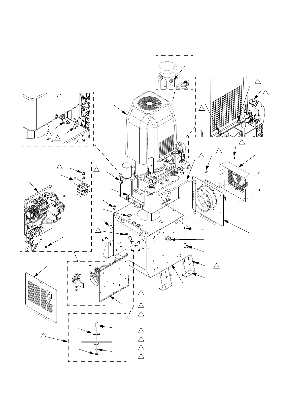
Parts
Mix Module Stand
61
54
2
76
6
59
69
54
2
86
3
87
3
54
77
6
54
2
55
1
2
75
5
74
62
56, 57
67
66
67
7
70
67
58
72
58
65
54
2
52
51
1
Fill power pack (55) tank with hydraulic oil. Check after initial startup to
ensure proper fluid level.
59
63
7
64
38 3A0238P
71
70
2
Apply anaerobic sealant to threads and torque to 17 ft-lbs (23 N•m).
3
Apply anaerobic pipe sealant to adapter fitting (86) threads and thread
in to power pack (55). Do not apply anaerobic pipe sealant to cap fitting
(87) threads.
4
Apply anaerobic sealant to threads and torque to 10 ft-lbs (13.5 N•m).
5
Apply anaerobic sealant to threads and torque to 6.5 ft-lbs (8.8 N•m).
6
Apply lubricant to threads and torque to 21 ft-lbs (28.4 N•m).
7
Tie wires here.
Page 39

230V Mix Module Stand
400V Mix Module Stand
Parts
Ref.
No. Part Description Qty
51 ENCLOSURE, frame 1
52 24D021 BRACKET, anchor, cube 4
54 111800 SCREW, cap, hex hd; 5/16-18 x
0.625
55 MODULE, hydraulic power, mix-
head; see page 44
56 U90205 WASHER, flat, 3/8, 0.41x1.25x.13,ms4
57 110385 SCREW, machine; hex hd; 5/16-18
x 3 in.
58 121160 GRIP, cord, 0.71-1.02 1
59 PANEL, mixhead, 230v 1
PANEL, mixhead, 400v 1
60 115942 NUT, hex, flange head 3
61 121171 GRIP, cord, 0.35-.63, 3/4 1
62 SWITCH, assy, disconnect, 230v 1
SWITCH, assy, disconnect, 400v 1
63 123452 HOLDER, anchor, wire tie, nylon 7
64 100166 NUT, full hex 7
65 PANEL, mixhead, assembly 1
66 123589 BUSHING, wire protector, snap-in 3
67 123398 PLUG, hole, 1-1/2 in. dia 5
68 123590 PLUG, hole, 2 in. dia 2
69 24B855 COVER, assembly; includes
69a-69c
69a COVER, hydraulic module 1
69b 117284 GRILL, fan guard 1
69c 103646 RIVET, blind 4
70 100020 WASHER, lock 7
71 116610 SCREW, mach, phillips, pan hd,
#10-32 x 1/2
72 COVER, enclosure, heat
exchanger, assy; see page 40
73 102795 SCREW, cap sch; #8-32 x 1.625 2
74 24C153 COVER, heat exchanger 1
75 113796 SCREW, flanged, hex hd; 1/4-20 x
3/4
76 24C621 HOSE, heat exchanger, inlet 1
77 15Y935 TUBE, heat exchanger, outlet 1
78 123855 HARNESS, 5 pin, adapter 1
79 122497 CABLE, cord set, reverse key 1
80 123303 HARNESS, m12 2
81 123673 HARNESS, ext, m12xm12, 5px5p,
mxf
82 123856 HARNESS, can cable, delete +24v 1
83 121201 CABLE, can, female-female, 6.0m 1
84 24C760 HARNESS, power, ac motor, 10ga 1
85 123764 HARNESS, m8, 4p, straight x pigtail 1
16
1
4
1
7
1
4
2
86 122970 FITTING, adapter, JIC(08) x
SAE(08), m
87 123140 FITTING, cap, 1/2 jic, cs 1
90 24D495 CORD, fan, heat exchanger, mix-
head
92 LABEL, identification, electronics 1
1
1
3A0238P 39
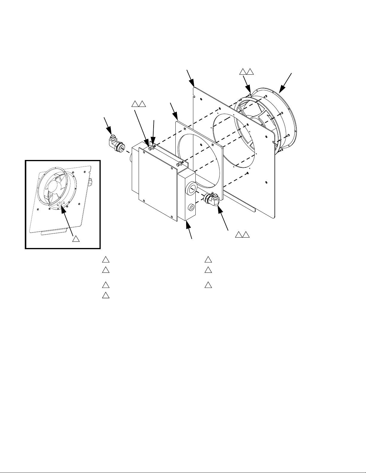
Page 40
Parts
Heat Exchanger Assembly
801
806
4 5
804
802
3 5
808
805
7
807
803
805
1 2
1
Torque to 65 ft-lb.
2
Apply lubricant to o-rings before
assembling.
3
Torque to 8 ft-lb.
4
Torque to 2.5 ft-lb.
Ref Part Description Qty
801 257967 COVER, enclosure, heat
1
exchanger
802 15X621 GASKET, fan, mounting 1
803 122300 EXCHANGER, heat, m-4 1
804 122301 FAN, 220v 1
805 122842 FITTING, elbow, SAE x JIC 2
806 15U075 SCREW, cap, bh, 8-32 x 0.375 8
807 110755 WASHER, plain 4
808 100022 SCREW, cap, hex hd; 1/4-20 x
4
3/4
5
Apply anaerobic sealant to threads.
6
Orient fan with airflow arrow pointing
toward cover.
7
Align fan plug as shown.
40 3A0238P
Page 41

Parts
3A0238P 41
Page 42

Parts
230V and 400V MixHead Panel
230V MixHead Panel Shown
See Electrical Schematics starting on page 58 for wire connections.
101
106
112
105
106
108
106
113
107
116
115
101
103
114
102
106
108
r_24c357_3a0238_3c
106, 108
117
122121
GND
120
110
111
109
119
GND
r_24c357_3a0238_6br_24c357_3a0238_5b
r_24c357_3a0238_7b
42 3A0238P
Page 43

230V and 400V MixHead Panels
Ref.
No. Part Description Qty
101 PANEL, electric, heat 1
102 289697 MODULE, cube, gca, base 1
103 102598 SCREW, cap, socket head; #10-32
x 1/2
104 289696 MODULE, gca, cube, fcm 1
105 24D207 POWER SUPPLY, 24vdc, 4A,
100w, 230vac in,
106 103833 SCREW, machine 11
107 MODULE, breaker, mixhead, 230v 1
MODULE, breaker, mixhead, 400v 1
108 123452 HOLDER, anchor, wire tie, nylon 3
109 100021 SCREW, cap hex hd; 1/4-20 x 1 1
110 100015 NUT, hex mscr 3
111 100028 WASHER, lock 3
112 116876 WASHER, flat 2
113 123718 FILTER, emi, 6a, spade con 1
114 121807 CONNECTOR, splitter 1
115★ 24D265 HARNESS, cable, can, 24vdc sup-
ply
116★ 123762 CABLE, can, 90x90, fxf, 0.5m 1
117★ 24E052 HARNESS, mixhead, e-stop, mtr
strt
118★ 24E211 HARNESS, mixhead, e-stop, mtr
str
119 114993 SCREW, pan washer hd; M4 x 0.7
x8mm
120 102063 WASHER, lock, ext 1
121 24F075 HARNESS, proximity, S-head 1
122 24D003 HARNESS, proximity, L-head, pig-
tail
Parts
4
1
1
1
1
1
1
★ See Electrical Schematics starting on page 58 for
wire connections.
3A0238P 43
Page 44

Parts
MixHead Hydraulic Power Pack
See Electrical Schematics starting on page 58.
See page 46 for assembly notes.
See Hose and Cable Kits starting on page 54.
240
201
247
241
242
244
5
13
See page 43.
206
2
221
14
12
222
252
266
256
238
255
239
257
244
5
13
241
243
203
205
4
13
202
1135
5
13
254
8
13
253
236
8
13
258
254
253
246
11
245
223
12
213
243
2
14
218
12
219
2
14
216
2
14
See page 43.
44 3A0238P
217
12
249
212
243
214
204
15
1135
2
3
3
14
13
13
237
Page 45

L-Head Configuration
13
7
13
3
225
234
268
2
14
15
228
2
269
230
14
216
224
273
272
227
235
12
226
6
Parts
9
14
252
270,
232
271
16
274,
275
7
13
S-Head Configuration
Refer to figure above for additional
omponent callouts.
7
20
210
16
231
263
233
209
16
226
229
230
9
2
15
14
14
231
228
2
14
3A0238P 45
Page 46

Parts
210
7
208
12
207
13
10
251
19
250
20
263
209
1
Assemble coupler (202, 212) to specified dimension prior to
mounting motor and pump to housing.
2
Torque to 40 ft-lbs (54 N•m).
3
Torque to 35 ft-lbs (47 N•m).
4
Torque to 70 ft-lbs (95 N•m).
5
Torque to 15 ft-lbs (20 N•m).
6
Torque to 185 in.-lbs (20 N•m).
7
Torque to 62 in.-lbs (7 N•m).
8
Torque to 65 in.-lbs (7.3 N•m).
9
Torque to 10 ft-lbs (13 N•m).
Torque to 40 in.-lbs (4.6 N•m).
10
Torque 1/4 turn past hand tight.
11
Apply PTFE tape on installation end only prior to assembly.
12
1
201
1.68
+.00
-.01
1
.07
+.00
-.01
212
202
211
Apply sealant to threads prior to assembly.
13
Apply a light coating of lubricant to seals prior to assembly.
14
Tighten tubing nuts hand tight and then with a wrench. Torque
15
1-1/2 flats.
Directional valves are supplied with o-rings.
16
Route all signal cables through cable ties on the filter side of the
17
power pack.
Route all power wires through cable ties on the filler side of the
18
power pack.
Apply lubricant to contact side of thermal switch harness (250)
19
prior to assembly.
Install roll pin (263) into diverter block (207) for orientation to
20
hydraulic housing (206).
Cables and leads removed for clarity.
21
46 3A0238P
Page 47

MixHead Hydraulic Power Module
Qty
Ref Part Description L-Head S-Head
201 122953 MOTOR, mixhead
202 16A954 COUPLER, motor
203 15Y675 PLATE, motor adapter
204 123338 SCREW, shc
205 C19852 SCREW, cap, socket head
206 15W772 HOUSING, hydraulic, module
207 16A599 BLOCK, diverter
208 100139 PLUG, pipe
209 556555 O-RING
210 104092 SCREW, cap, sch
211 122966 PUMP, gear, hydraulic
212 16A955 COUPLER, pump
213 16A956 COUPLER, spider
214 123942 FASTENER, screw, cap, hex hd
216 115597 FITTING, nipple
217 15Y696 TUBE, pump to manifold
218 101353 FITTING, nipple, pipe
219 122606 FITTING, elbow, male, female
220 100627 NIPPLE, short
221 127953 VALVE, relief, anti-shock
222 100721 PLUG, pipe
223 101754 PLUG, pipe
224 15Y629 HOUSING, adapter, mixhead
225 C19834 SCREW, cap, socket hd
226 122962 PLUG, sae 03
227 17B775 GAUGE, pressure, 0-5000 psi
228 122964 PLUG, sae 08
229 122970 FITTING, adapter, jic(08)xsae(08)
230 122967 FITTING, elbow, swivel, 90, jic(08)
231 16K154 BLOCK, blank
24D636 VALVE, cleanout, wiring, assembly
232 24D634 VALVE, acc loading, wiring, assembly
233 125736 VALVE, directional, 1 sol, 24vdc
234 123366 SCREW, shc
235✖ 257432 HARNESS, wire, transducer
236 15X622 GASKET, housing, to, tank
237 257162 RESERVOIR, assembly, 8 gallon
238 101971 WASHER, thrust
239 111302 SCREW, cap, hex hd
240 15Y680 PLATE, accumulator mounting
241 123293 BRACKET, accumulator mounting
242 122952 ACCUMULATOR, mixhead
243 121312 FITTING, elbow, sae x jic
244 110963 SCREW, cap, flange head
245 15J937 FILTER, oil, 18-23 psi bypass
246 116915 CAP, breather filler
247 15Y684 TUBE, manifold to accumulator
248 121486 FITTING, elbow, male, 1/2jicx1/2npt
249 123528 FITTING, elbow, swivel, 45, jic08, fm, 6k
11
11
11
44
44
11
11
22
48
48
11
11
11
22
21
11
11
11
11
11
11
11
11
44
44
11
02
42
53
1
1
11
11
84
11
11
11
44
44
11
22
11
33
44
11
11
11
11
11
Parts
3A0238P 47
Page 48

Parts
250 123367 HARNESS, m8 x thermal switch, 4-pin
251 102410 SCREW, cap soc hd
252 103413 PACKING, o-ring
253 123601 CLAMP, wire, harness, nylon, 3/4"
254 103833 SCREW, mach, crbh
255▲ 189285 LABEL, caution
256▲ 121208 LABEL, hot surface
257 257976 SUPPORT, tank to motor, ac power pack
258 113802 SCREW, hex hd, flanged
263 123786 FASTENER, pin, roll
266 112395 SCREW, cap
267✖ 125102 HARNESS, din18, 3p, elbow
268 127952 ACCUMULATOR, hydraulic
269 127955 FITTING, adapter
270 127963 MANIFOLD
271 127954 VALVE, check, 100 psi
272 123253 VALVE, needle, 1/4 NPT
273 156971 FITTING, nipple, short
274 116575 SCREW, cap
275 100020 WASHER, lock
▲ Replacement Danger and Warning labels, tags, and
cards are available at no cost.
✖ Not shown.
11
22
22
77
77
11
11
11
22
12
44
11
11
11
11
11
11
11
44
44
48 3A0238P
Page 49

Parts
3A0238P 49
Page 50

Parts
Pneumatic Boom Arm
311
313
313
312
318
338
T
o cylinder
322
332
325
326
324
317
317
319
320, 321
3
1
322
3
308
315
314
323
3
316
328
333
2
336
310
305
309
335
2
329
2
305
307
301
334
2
330
331
1
304
2
To manifold
305
337
303
1
Torque to 35 ft-lbs (47.5 N•m).
2
Hand tighten only. Do not torque.
3
Apply PTFE tape on installation end only prior to assembly.
50 3A0238P
302
305
r_257553_3a0238_2a
3
327
307
2
306
Page 51

Pneumatic Boom Arm
3
Ref.
No. Part Description Qty
301 24D349 BASE, boom assembly
302 BEARING, thrust, 45 x 65 x 14
303 15Y044 BEARING, support
304 113470 BOLT, hex
305 109570 WASHER, plain
306 100018 WASHER, lock, spring
307 100338 NUT, jam
308 POST, boom assembly
309 122634 COLLAR, 2.875 clamp 1pc
310 100096 SCREW, cap, hex hd; 1/2-13 x 2
311 ARM, boom assembly
312 15Y045 PIN, pivot, arm, boom
313 122633 COLLAR, 1.125 clamp 1pc
314 122653 CYLINDER, air, with nut
315 122640 BEARING, bronze,1/2 x 3/4 x 1/2
316 122652 ROD, clevis, w/pin
317 122646 BEARING, flange,1/2 x 3/4, bronze
318 122635 COLLAR, 1/2 clamp 1pc
319 122637 PIN, clevis,1/2 x 3-1/2,sst
320 15Y065 BUSHING, 1/2 x 1/4 npt, mf, ss, 6k,
316
321 15Y064 FITTING, plug, 1/4 npt, modified
322 116654 FITTING, tube, swivel, male elbow
323 122648 MUFFLER, 1/2 npt
324 122638 BOLT, EYE, 0.38-16 x 4-1/4
325 100133 WASHER, lock
326 100731 WASHER
327 100054 FITTING, lubtn, st
328 122650 VALVE, solenoid, 4way 3pos w/lvr
329 517449 MUFFLER, sintered, 1/4/ npt
330 121643 FITTING, elbow,1/4 x 1/4 npt,
swivel, ext
331 100721 PLUG, pipe
332 103893 ELBOW, street
333 122651 VALVE, bleed nmf 20 10 sk
334 15B588 SCREW, socket hd cap; 1/4-20 x
1.5
335 100015 NUT, hex mscr
336 100016 WASHER, lock
337 54106 TUBE, plyeth 0.375 OD
338 54118 TUBE, polyethylene
339 U70068 LABEL, stripe, 2in.,yellow/black
10
12
Parts
1
1
1
1
5
5
1
1
4
1
1
2
1
1
1
2
2
1
1
1
2
1
1
1
6
3
1
1
1
2
1
1
3
3
3
7
2
3A0238P 51
Page 52

Parts
Hose Kits
L-Head Hose Kit Shown
413
1
3
416
413
1
3
402
404
11
15
402
10
417
403
401
401
416
405
408
406
406
410
403402
411
401
401
8
409
407
13
1214
403
2
414
1 3
5
412
2
401
4
421
7
423
9
424
6
422
r_24d628_3a0238_1h
1
Wrap bundle of hose with electrical tape every 2 ft.
2
Torque to 6 ft-lbs (8 N•m).
3
Wrap electrical tape on each end of scuff guard (413, 414, and
420)
4
Connect to B (blue) side on system manifold.
5
Connect to A (red) side on system manifold.
6
Connect to B (blue) side tank stand.
7
Connect to A (red) side tank stand.
8
Connect to B side supply fitting on applicator.
9
Connect to B side return fitting on applicator.
52 3A0238P
Connect to A side supply fitting on applicator.
10
Connect to A side return fitting on applicator.
11
Connect material open hose to B2 connection marked on
12
mixhead housing adapter (224).
Connect material close hose to A2 connection marked on
13
mixhead housing adapter (224).
Connect clean-out open hose to B1 connection marked on
14
mixhead housing adapter (224).
Connect clean-out close hose to A1 connection marked on
15
mixhead housing adapter (224).
16. Torque all screws on hydraulic and material hose clamps to 6
ft-lbs (8 N•m).
Page 53

Hose Kits
Quantity
Boom Hose Kits No Boom Hose Kits
Ref Part Description
401✿ 24A524 HOSE, assy, hydraulic, 3/8, 20 ft (6
m); JIC 8; 4000 psi
402 262193 HOSE, A, 25 ft. (7.6 m), 1/2 in.,
moisture-lock
403 262194 HOSE, B, 25 ft. (7.6 m), 1/2 in.,
moisture-lock
404 123896 FITTING, swivel, JIC 8(f) x JIC 8(f) 2 2 2 2
405 123897 FITTING, swivel, JIC10(f)x JIC10(f) 2 2 2 2
406 122643 NUT, rail 40 20
407 122644 CLAMP, hose, 3/8 in. 20 40
408 122645 PLATE, cover 20 20
409 107218 SCREW, cap, sch; 1/4-20 x 2.75 20 20
410 123100 CLAMP, hose, boom, 7/8 in. 20 20
411 123070 COVER, plate 10 10
412 104594 SCREW, cap; 1/4-20 x 3.25 20 20
413‡ JACKET, scuff, 7 ft. (2.1 m) 2 2
414‡ JACKET, scuff, 15 ft. (4.5 m) 2 2
416 122642 SNAP, spring, 140#, 3/8, 1/4, zinc 2 2
417 122641 CHAIN, 3/16 OD 1 1
418✖✿ 24D002 HARNESS, proximity, material dis-
pense, L-Head, ext
123660 HARNESS, proximity, material dis-
pense, S-Head, ext
419✖✿ 24D004 HARNESS, proximity, clean-out,
L-head, 20 ft. (6 m)
420‡ JACKET, scuff 25 ft. (7.6m) 1 1
421 262191 HOSE, A, 10 ft. (4.6 m), 1/2 in.,
moisture-lock
422 262192 HOSE, B, 10 ft (4.6 m), 1/2 in., mois-
ture-lock
423 123106 FITTING, elbow, (08) JIC x 1/2 npt;
sst
424 123107 FITTING, elbow, (10) JIC x 1/2 npt;
sst
425✖ 124527 HARNESS, male, cap, jumper 1 1
L-Head S-Head L-Head S-Head
4 2 4 2
2 2 2 2
2 2 2 2
1 1
1 1
1 1
1 1 1 1
1 1 1 1
1 1 1 1
1 1 1 1
Parts
426✖ 124528 HARNESS, resistor ; m12(m) x
m12(f); 7.8 in. (198.12 mm)
✖ Not shown.
‡ Order 24E954 for replacement scuff guard. Contains
200 ft (60.9 m) of braided polyester mesh.
✿ See Hose and Cable Kits on page 54 for additional
sizes.
See manual 3A0862 for material and hydraulic hose
extensions.
3A0238P 53
1 1
Page 54

Hose and Cable Kits
Hose and Cable Kits
Required for power pack modules 24F297 and 24F298.
Length
ft (m)
Heated or Unheated A and B Material Hoses
Maximum operating pressure: 3500 psi (24 MPa, 241 bar)
10 ft (4.6 m)
25 (7.6)
50 (15.2)
Hydraulic and Material Hose Extension Kits; see manual 3A0862
25 (7.6) 24F237 24F235 1
50 (15.2) 24F238 24F236 1
Hydraulic Hose Assemblies
Maximum operating pressure: 4000 psi (28 MPa, 275 bar)
20 (6) 24A524 24A524 (4) 2 (4)
25 (7.6) 24F257 24F257 (4) 2 (4)
50 (15.2) 24F258 24F258 (4) 2 (4)
Proximity Sensor Cable (426)
7.8 in. (198.12 mm) 124528 1
Termination Connector Cap (425)
NA 124527 1
Material Proximity Cable Harness
20 (6) 123660 24D002 1
25 (7.6) 123658 24F239 1
50 (15.2) 123659 24F240 1
L-Head Cleanout Proximity Cable Harness
20 (6) 24D004 1
25 (7.6) 24F241 1
50 (15.2) 24F242 1
Compatible Applicators and Part Number
See manual 3A0237 for
part numbers.
See manual 3A0237 for
part numbers.
Qty.S-Head L-Head
4
54 3A0238P
Page 55

Optional Equipment
Optional Equipment
Fluid Level Sensor 24E347 Hydraulic Pressure Gauge Kit 24C872
6°
206
515
3
503
2
502
1
513
1
501
2
r_257840_3a0238_24e347
1
Torque to 16 in.-lbs (1.8 N•m.
2
Connect cable (502) to (503).
3
Route and cable tie (503) with existing signal-wire bundle
and connect free end of (503) to port #3 of FCM.
222
1
Apply sealant to threads prior to assembly.
2
Remove plug (222) from (206).
3
Verify alignment for pump and cover clearance. Adjust
(512) angle as required.
1
516
512
r_257840_3a0238_24c872
1
511
514
1
Ref.
No. Part Description Qty
501 C19950 SCREW, cap, sch; #4-40
502 123549 SENSOR, assy, level, cap, proxim-
ity
503 121686 CABLE, m8 x m8, 4p,fxm,stxrt,
2m
Ref.
No. Part Description Qty
2
511 156971 FITTING, nipple, short
1
512 108417 ELBOW, female
513 177021 NIPPLE, pipe, hex
1
514 113093 CONNECTOR, pipe
515 804582 GAUGE, pressure, 0-500 psi
516 C19337 FITTING, nipple
1
1
1
2
1
1
3A0238P 55
Page 56

Optional Equipment
Hydraulic RTD Sensor Kit 24E348
522
1
521
1
Apply sealant to threads prior to assembly.
2
Remove plug (223) from (206).
3
Connect signal end of (523) to (524).
4
Route and cable tie (524) with existing signal-wire bundle
and connect free end of (524) to port #4 of FCM.
5
Apply a minimal amount of thermal grease to contact end
of (523).
r_257840_3a0238_24E348
523
524
4
3
5
Ref.
No. Part Description Qty
521 15T071 HOUSING, temp, rtd
522 15T072 GRIP, cord, straight through
523 124262 SENSOR, rtd, 1 kohm, 6 ft
524 121686 CABLE, m8 x m8, 4p,fxm,stxrt,
2m
1
1
1
1
56 3A0238P
Page 57

Optional Equipment
3A0238P 57
Page 58

Optional Equipment
Electrical Schematics
230V Power Pack
654
-+
321
-+
125736
DISPENSE
LABEL A1
CBADCBA
D
GRD
RED
1711
1710
BLK
CBADCBA
D
BLUBRN
321
321
RELAY
DISPENSE
43215
43215
43215
LABEL CAN 1
23415
LABEL SPL 1
43215
432
1
1
5
432
5
24D359
HARNESS
24D359
HARNESS
24D636
HARNESS
LABEL SPL 2
24D265
2
1
2
24D634
CLEAN-OUT
ACCUM
1
58 3A0238P
Page 59

230V Power Pack - 2
Optional Equipment
LABEL 2A
TYPICAL
24D634
CBA
CBA
3 1 2
LABEL 2C
123764
ACCUM
SOL205
1
2
OPEN
3
ACCUM
CLOSE
SOL211
4
1
5
2
345
LABEL 2C
1
CBA
24D004
CBA
2
3
4
HARNESS
OIL TEMP
RTD290
M24022
HARNESS
15R347
PX249
PROX
(L HEAD ONLY)
CLEAN-OUT OPEN
23451
FEMALE
123855
M12 5 PIN
HARNESS
121201
M12 5 PIN
HARNESS
123856
M12 5 PIN
4321 5
118
CONNECT WITH 123762
CABLE FROM
MALE
M12 5 PIN
FEMALE
MALE
121807 SPLITTER
23451
23451
LABEL CAN 2
43215
COMMON
SIGNAL
SIGNAL
SIGNAL
SIGNAL
MALE
123303
M12 5 PIN
HARNESS
HARNESS
123673
FEMALE
M12 5 PIN
MALE
M12 5 PIN
FEMALE
M12 5 PIN
5
4
6
24C292
HARNESS
HARNESS
123303
3
7
2
0
1
M12 5 PIN
HARNESS
123673
M12 5 PIN
M12 5 PIN
MALE
M12 5 PIN
FEMALE
MALE
FEMALE
GND
LABEL 1B
1
1
SIGNAL
SIGNAL
432155
43215
43215
432
1 2
43215
43215
432
SIGNAL
COMMON
5
54321
SIGNAL
LABEL 2
LABEL 2
#1 FLUID CONTROL
MODULE FRONT VIEW
LABEL 1 LABEL 2
LABEL 1
LABEL 1
MALE
M8 4 PIN
HARNESS
121686
FEMALE
M8 4 PIN
HARNESS
M8 4 PIN
121686
M8 4 PIN
123549
EXC
1
1
MALE
M8 4 PIN
1
1
FEMALE
M8 4 PIN
1
FEMALE
M8 4 PIN
1
MALE
1
FEMALE
M8 4 PIN
1
MALE
HYL-OIL
LO-LVL
(OPTION)
SIGNAL
4
3
PX247
432
432
432
432
432
432
432
432
LABEL 4
LABEL 4
LABEL 4
4321 54321 5
CAN COM 1 CAN COM 2
LABEL 3
LABEL 3
LABEL 1A
200
201
24D636
202
1
203
2
SOL204
CLEAN OUT
204
205
3
EXTEND
206
207
208
4
209
5
SOL210
CLEAN OUT
210
211
RETRACT
212
213
214
1
2
345
220
221
218
216
219
215
217
222
223
224
225
226
1
2
3
227
4
LABEL 1C
230
228
229
OIL TEMP
232
231
HI
234
233
123367
OTS234
236
235
237
238
239
240
241
242
243
244
245
246
247
248
249
FEMALE
M12 5 PIN
MALE
M12 4 PIN
16K749
HARNESS
43214
432
1
L-HEAD = PLUG INTO FCM #1, PORT 1B ABOVE
S-HEAD = PLUG INTO MCM #1, PORT 2B ON HFR UNIT
LABEL 2A
3120
3130
A2
RELAY
A1
CR309
DISPENSE
125740
SEE PAGE 2/5
3A0238P 59
Page 60

Optional Equipment
230V Power Pack - 3
PRESS XDUCER
PX270
TYPICAL
HARNESS
1562
164
24F075
1561
DC COM
GND
1560
+24V DC
24C292
HARNESS
24E052
HARNESS
FEMALE
M12 5 PIN
ATTAC H
IF L-HEAD
HARNESS
122497
2650
2650
AT LEFT
SHOWN
DEVICE
+5VDC
MALE
M12 5 PIN
FEMALE
M12 5 PIN
MALE
M12 5 PIN
1
FEMALE
M12 5 PIN
1
FEMALE
M12 8 PIN
2651
2651
54321
LABEL 5ALABEL 5A
-SIG
+SIG
DC COM
43215
43215
43215
432
5 6
432
24E211
HARNESS
SHLD
55
54321
DC COM
LABEL 6
LABEL 6
LABEL 6
876
876
2790
CYCLE-STOP
1561
DC COM
#1 FLUID CONTROL
MODULE BACK VIEW
LABEL 5
123362
C_STOP
2860
A2
A1
1561
DC COM
X0
123362
MTR_STRT
FEMALE
M12 5 PIN
7
54321
HARNESS
124527
250
251
252
253
254
255
256
MALE
M12 5 PIN
258
259
257
260
261
262
263
264
265
54321
ONLY
L-HEAD
USE WITH
299
297
266
267
268
269
270
271
272
273
274
275
276
277
278
279
280
281
282
283
284
285
286
287
288
289
290
291
292
293
294
295
296
298
300
301
302
303
304
305
306
307
308
309
310
311
312
313
314
315
316
317
318
317
318
319
300
60 3A0238P
Page 61

230V Power Pack - 4
Optional Equipment
AB
PT
AB
B
B
M
PT
A
3A0238P 61
Page 62
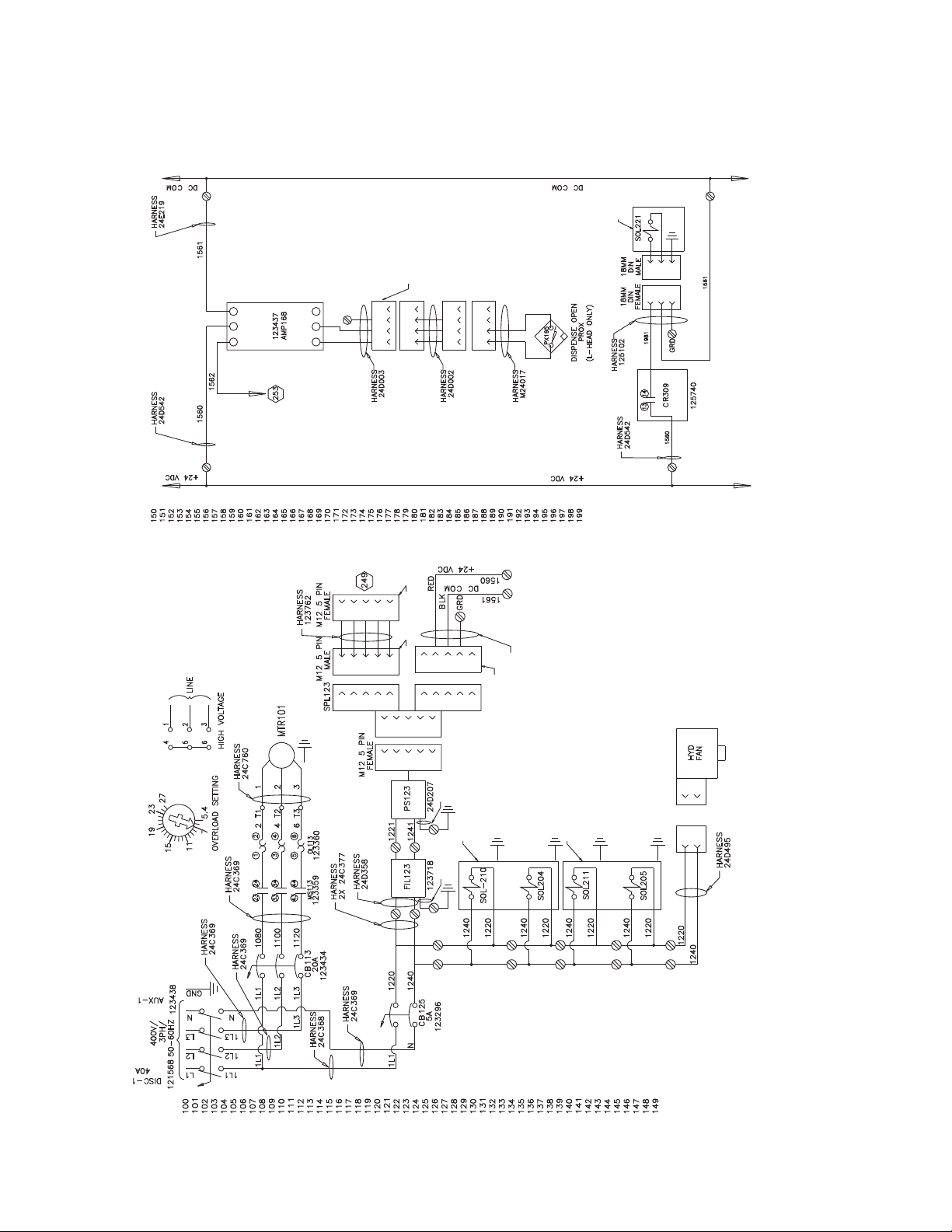
Optional Equipment
400V Power Pack
125736
DISPENSE
LABEL A1
321
321
CBADCBA
432
5
432
5
432
5
1
D
LABEL CAN 1
LABEL SPL 1
432
5
GRD
654
-+
321
RED
1711
-+
1710
BLK
1
1
1
CBADCBA
23415
43215
D
HARNESS
LABEL SPL 2
24D265
BLUBRN
RELAY
DISPENSE
432
1
5
24D359
HARNESS
24D359
HARNESS
24D636
2
1
2
CLEAN-OUT
24D634
ACCUM
1
62 3A0238P
Page 63

400V Power Pack -2
24D634
LABEL 2C
Optional Equipment
CBA
CBA
312
CBA
LABEL 2A
1
LABEL 1B
LABEL 2C
2
3
4
1
5
2
3
4
1
5
2
3
4
23451
CBA
43215
LABEL 2
43215
1
1
LABEL 2
43215
432155
1 2
432
1
1
1
3 4
1
1
LABEL 4
432
432
LABEL 4
432
LABEL 4
432
43215
23451
23451
43215 43215
432
CONNECT WITH 123762
CABLE FROM
LABEL CAN 2
121807 SPLITTER
432
43215
LABEL 3
432
LABEL 3
432
LABEL 3
43215
LABEL 1 LABEL 2
LABEL 1
54321
LABEL 1
1
1
LABEL 1A
LABEL 1C
24D636
3A0238P 63
Page 64

Optional Equipment
400V Power Pack -3
LABEL 6
4
3
2
1
1
1
5
4
3
2
5
LABEL 6
LABEL 6
4
3
2
5
1
AT TAC H
2
L-HEAD
DEVICE
4
3
2
1
1
1
5
4
3
LABEL 5ALABEL 5A
AT LEFT
SHOWN
55
5 6
4
3
2
4
3
2
8
7
6
5
8
7
6
LABEL 5
7
5
4
3
2
1
4
3
2
1
LABEL 2A
RELAY
DISPENSE
5
4
3
2
1
USE WITH
L-HEAD
64 3A0238P
Page 65

400V Power Pack -4
300
301
302
303
304
305
306
307
308
309
310
311
312
313
314
315
316
317
318
319
320
321
322
323
324
325
326
327
328
329
330
331
332
333
334
335
336
337
338
339
340
341
342
343
344
345
346
347
348
349
350
351
352
353
354
355
356
357
358
359
360
361
362
363
364
365
366
367
368
369
370
371
372
373
374
375
ACCUMULATOR
60 CU. IN.
1200 PSI PRECHARGE
ANTI-SHOCK
PRESSURE
RELIEF
VALVE
CLOSED
A
SANDWICH
CHECK VALVE
100 PSI CRACK
P
AB
DIRECTIONAL VALVE
PT
AB
T
GUN TRIGGER
PRESSURE
TRANSDUCER
PRESSURE
GAUGE
ACCUMULATOR
DIRECTIONAL VALVE
B
M
5 HP
230/400/3/50-60
1750 RPM
PUMP
Optional Equipment
LOCATED ON THE MIX HEAD
HYDRAULIC POWER PACK
ACCUMULATOR
10 CU. IN.
100 PSI PRECHARGE
ESTCODE
OIL OVERTEMP
SWITCH
HEAT
EXCHANGER
FILTER
OIL LEVEL
SENSOR
3A0238P 65
Page 66

Dimensions
Dimensions
AC Power Pack Module
Front View
Top View
7.7 ft (2.3 m)
Side View
26 in.
(660.4 mm)
8.4 ft
(2.5 m)
See page 67 for mounting dimensions.
66 3A0238P
Page 67

Mounting Dimensions
(330 mm)
13 in.
Dimensions
24 in. (609.6 mm)
AC Power Pack Stand
page 68
5 in.
(127 mm)
22 in.
(558.8 mm)
Pneumatic
Boom
page 69
14 in.
(355.6 mm)
3A0238P 67
Page 68

Dimensions
AC Power Pack Stand
Front View Side View
4.7 ft
(1.4 m)
26 in.
(660.4 mm)
r_24c065_3a0238_8d
13 in.
(330 mm)
r_24c065_3a0238_9d
19.48 in. (494.79 mm)
Top View
18 in.
(457.2 mm)
r_24c065_3a0238_10d
24 in. (609.6 mm)
68 3A0238P
Page 69

Pneumatic Boom
Front View
8.4 ft
(2.5 m)
Dimensions
Side View
16 in.
(406.4 mm)
r_24d628_3a0238_2h
r_24d628_3a0238_3h
7.7 ft (2.3 m)
Mounting Dimensions
24 in.
(609.6 mm)
14 in.
(355.6 mm)
22 in. (558.8 mm)
3A0238P 69
Page 70

Technical Data
Technical Data
Maximum hydraulic fluid working pressure .......... 2500 psi (17 MPa, 172 bar)
Minimum hydraulic hose working pressure .......... 3000 psi (21 MPa, 207 bar)
Maximum hydraulic fluid temperature .............. 180°F (82°C)
Maximum ambient temperature................... 120°F (49°C)
Hydraulic reservoir capacity ..................... 10gallons (38 liters)
Recommended hydraulic fluid .................... ISOVGNumber 46 or ASTM Grade 215
Accumulator hydraulic fluid capacity ............... 1gallon (3.8 liters)
Accumulator precharge ......................... 1200 psi (nitrogen)
Accumulator precharge (small) ................... 150 psi (1.0 MPa, 10 bar)
Accumulator capacity (small)..................... 10in^3 (164 cc)
Maximum Weight.............................. 415lbs(188 kg)
Minimum cycle time ............................ 7seconds (shot time + time between shots)
Voltage (Phase)
230V Mix Module Stand ........................ 230(3)
400V Mix Module Stand ........................ 400(3)
Power Pack Maximum Amperage
230V System ................................. 17A
400V System ................................. 18A
70 3A0238P
Page 71

Technical Data
3A0238P 71
Page 72

Graco Standard Warranty
Graco warrants all equipment referenced in this document which is manufactured by Graco and bearing its name to be free from defects in
material and workmanship on the date of sale to the original purchaser for use. With the exception of any special, extended, or limited warranty
published by Graco, Graco will, for a period of twelve months from the date of sale, repair or replace any part of the equipment determined by
Graco to be defective. This warranty applies only when the equipment is installed, operated and maintained in accordance with Graco’s written
recommendations.
This warranty does not cover, and Graco shall not be liable for general wear and tear, or any malfunction, damage or wear caused by faulty
installation, misapplication, abrasion, corrosion, inadequate or improper maintenance, negligence, accident, tampering, or substitution of
non-Graco component parts. Nor shall Graco be liable for malfunction, damage or wear caused by the incompatibility of Graco equipment with
structures, accessories, equipment or materials not supplied by Graco, or the improper design, manufacture, installation, operation or
maintenance of structures, accessories, equipment or materials not supplied by Graco.
This warranty is conditioned upon the prepaid return of the equipment claimed to be defective to an authorized Graco distributor for verification of
the claimed defect. If the claimed defect is verified, Graco will repair or replace free of charge any defective parts. The equipment will be returned
to the original purchaser transportation prepaid. If inspection of the equipment does not disclose any defect in material or workmanship, repairs will
be made at a reasonable charge, which charges may include the costs of parts, labor, and transportation.
THIS WARRANTY IS EXCLUSIVE, AND IS IN LIEU OF ANY OTHER WARRANTIES, EXPRESS OR IMPLIED, INCLUDING BUT NOT LIMITED
TO WARRANTY OF MERCHANTABILITY OR WARRANTY OF FITNESS FOR A PARTICULAR PURPOSE.
Graco’s sole obligation and buyer’s sole remedy for any breach of warranty shall be as set forth above. The buyer agrees that no other remedy
(including, but not limited to, incidental or consequential damages for lost profits, lost sales, injury to person or property, or any other incidental or
consequential loss) shall be available. Any action for breach of warranty must be brought within two (2) years of the date of sale.
GRACO MAKES NO WARRANTY, AND DISCLAIMS ALL IMPLIED WARRANTIES OF MERCHANTABILITY AND FITNESS FOR A
PARTICULAR PURPOSE, IN CONNECTION WITH ACCESSORIES, EQUIPMENT, MATERIALS OR COMPONENTS SOLD BUT NOT
MANUFACTURED BY GRACO. These items sold, but not manufactured by Graco (such as electric motors, switches, hose, etc.), are subject to
the warranty, if any, of their manufacturer. Graco will provide purchaser with reasonable assistance in making any claim for breach of these
warranties.
In no event will Graco be liable for indirect, incidental, special or consequential damages resulting from Graco supplying equipment hereunder, or
the furnishing, performance, or use of any products or other goods sold hereto, whether due to a breach of contract, breach of warranty, the
negligence of Graco, or otherwise.
FOR GRACO CANADA CUSTOMERS
The Parties acknowledge that they have required that the present document, as well as all documents, notices and legal proceedings entered into,
given or instituted pursuant hereto or relating directly or indirectly hereto, be drawn up in English. Les parties reconnaissent avoir convenu que la
rédaction du présente document sera en Anglais, ainsi que tous documents, avis et procédures judiciaires exécutés, donnés ou intentés, à la suite
de ou en rapport, directement ou indirectement, avec les procédures concernées.
Graco Information
For the latest information about Graco products, visit www.graco.com.
TO PLACE AN ORDER, contact your Graco distributor or call to identify the nearest distributor.
Toll Free: 1-800-746-1334 or Fax: 330-966-3006
All written and visual data contained in this document reflects the latest product information available at the time of publication.
GRACO INC. AND SUBSIDIARIES • P.O. BOX 1441 • MINNEAPOLIS MN 55440-1441 • USA
Copyright 2010, Graco Inc. All Graco manufacturing locations are registered to ISO 9001.
Graco reserves the right to make changes at any time without notice.
For patent information, see www.graco.com/patents.
2ULJLQDOLQVWUXFWLRQV7KLVPDQXDOFRQWDLQV(QJOLVK00$
Graco Headquarters: Minneapolis
International Offices: Belgium, China, Japan, Korea
www.graco.com
Revised November 2014
 Loading...