

Page 1
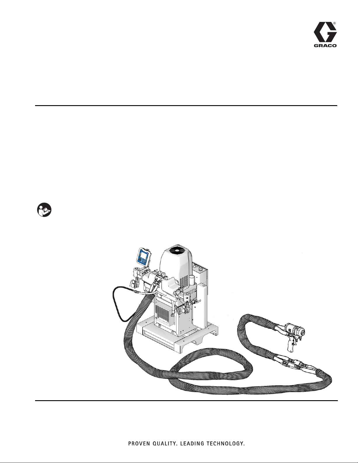
Instructions-Parts
Heated Hoses and
3A0237L
Applicator Kits
For use with Graco® HFR™ Metering Systems.
Not approved for use in European explosive atmospheres. For professional use only.
See page 2 for Maximum Fluid Working Pressures and approvals.
130 psi (0.9 MPa, 9 bar) Maximum Air Working Pressure
180°F (82°C) Maximum Hose Operating Temperature
EN
Important Safety Instructions
Read all warnings and instructions in this manual.
Save these instructions.
Page 2

Related Manuals
Contents
Related Manuals . . . . . . . . . . . . . . . . . . . . . . . . . . . 2
Heated Hose Bundle Part Numbers . . . . . . . . . . . . 3
Fluid Temperature Sensor (FTS) . . . . . . . . . . . . . 4
Heated Whip Hose . . . . . . . . . . . . . . . . . . . . . . . 4
Individual Hoses . . . . . . . . . . . . . . . . . . . . . . . . . . . 5
Applicator Kits . . . . . . . . . . . . . . . . . . . . . . . . . . . . . 9
MD2 Valve Applicator Kits . . . . . . . . . . . . . . . . . 10
Warnings . . . . . . . . . . . . . . . . . . . . . . . . . . . . . . . . 11
Important Two-Component Material Information 14
Isocyanate Conditions . . . . . . . . . . . . . . . . . . . . 14
Material Self-ignition . . . . . . . . . . . . . . . . . . . . . 14
Keep Components A and B Separate . . . . . . . . 14
Moisture Sensitivity of Isocyanates . . . . . . . . . . 14
Foam Resins with 245 fa Blowing Agents . . . . . 14
Changing Materials . . . . . . . . . . . . . . . . . . . . . . 15
A and B Components . . . . . . . . . . . . . . . . . . . . . . 15
Installation . . . . . . . . . . . . . . . . . . . . . . . . . . . . . . . 16
Description . . . . . . . . . . . . . . . . . . . . . . . . . . . . 16
Connect Whip Hose to Gun or Gun Manifold . . 16
Connect Heated Hoses . . . . . . . . . . . . . . . . . . . 17
Connect FTS and Heated Whip Hose . . . . . . . . 20
Connect Solenoid Kit . . . . . . . . . . . . . . . . . . . . 21
Check Hoses for Leaks . . . . . . . . . . . . . . . . . . . 22
Protective Covering . . . . . . . . . . . . . . . . . . . . . . 22
Operation . . . . . . . . . . . . . . . . . . . . . . . . . . . . . . . . 23
Maintenance . . . . . . . . . . . . . . . . . . . . . . . . . . . . . . 24
Instructions for Replacing Individual A or B Hose 24
Clean Orifice . . . . . . . . . . . . . . . . . . . . . . . . . . . 24
Bundle Individual Whip Hoses . . . . . . . . . . . . . 26
Bundle Individual Heated Hoses . . . . . . . . . . . . 28
Parts . . . . . . . . . . . . . . . . . . . . . . . . . . . . . . . . . . . . 30
Whip Hoses . . . . . . . . . . . . . . . . . . . . . . . . . . . . 30
Heated Hose Bundles . . . . . . . . . . . . . . . . . . . . 32
Using Fluid Temperature Sensors For Single Heat
Zones . . . . . . . . . . . . . . . . . . . . . . . . . . . . . 35
Using Fluid Temperature Sensors for Dual Heat
Zones . . . . . . . . . . . . . . . . . . . . . . . . . . . . . 35
MD2 Applicator Kits . . . . . . . . . . . . . . . . . . . . . 37
Accessories . . . . . . . . . . . . . . . . . . . . . . . . . . . . . . 38
Scuff Guard . . . . . . . . . . . . . . . . . . . . . . . . . . . . 38
Solenoid Kits . . . . . . . . . . . . . . . . . . . . . . . . . . . 38
Technical Data . . . . . . . . . . . . . . . . . . . . . . . . . . . . 40
Graco Standard Warranty . . . . . . . . . . . . . . . . . . . 42
Graco Information . . . . . . . . . . . . . . . . . . . . . . . . 42
Related Manuals
Component Manuals in U.S. English:
Manual Description
313997 HFR Operation
313998 HFR, Repair-Parts
313872
312185 MD2 Valve, Instructions-Parts
312666
310649
309550
309856
3A0861 Ratio Check Assembly, Instructions-Parts
™
EP
Gun, Instructions-Parts
Fusion
ment Mix Spray Gun with ClearShot
uid Technology, Instructions-Parts
Fusion Automatic Plural Component,
Impingement Mix Spray Gun, Instructions-Parts
Fusion Air Purge Plural Component,
Impingement Mix Spray Gun, Instructions-Parts
Fusion Mechanical Purge Plural Component, Impingement Mix Spray Gun,
Instructions-Parts
™
CS Plural Component, Impinge-
™
Liq-
2 3A0237L
Page 3

Heated Hose Bundle Part Numbers
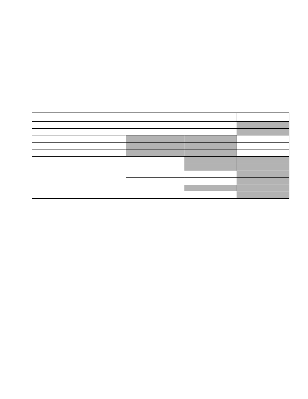
Heated Hose Bundle Part Numbers
Each hose contains an A component hose, a B component hose, and an air hose (1/4 npt x 1/4 npsm, m x f).
Single Hose Part No. JIC Fittings Maximum Fluid
ID
Part No. Ratio
Stainless Steel Dual Heat Zone Hose Bundle with Air Hose
24D108 2:1 1/4 (6) A x 3/8 (10) B 5 (1.5) 24E925 24E934 5/5 6/6 3500 (24, 241)
24D109 2:1 1/4 (6) A x 3/8 (10) B 10 (3) 24E927 24E936 5/5 6/6 3500 (24, 241)
24D110 2:1 1/4 (6) A x 3/8 (10) B 25 (7.6) 24E929 24E938 5/5 6/6 3500 (24, 241)
24D111 2:1 1/4 (6) A x 3/8 (10) B 50 (15.2) 24E931 24E940 5/5 6/6 3500 (24, 241)
24D112 1:1 3/8 (10) A x 3/8 (10) B 5 (1.5) 24E933 24E934 5/5 6/6 3500 (24, 241)
24D113 1:1 3/8 (10) A x 3/8 (10) B 10 (3) 24E935 24E936 5/5 6/6 3500 (24, 241)
24D114 1:1 3/8 (10) A x 3/8 (10) B 25 (7.6) 24E937 24E938 5/5 6/6 3500 (24, 241)
24D115 1:1 3/8 (10) A x 3/8 (10) B 50 (15.2) 24E939 24E940 5/5 6/6 3500 (24, 241)
Carbon Steel Dual Heat Zone Hose Bundle with Air Hose
24D116 2:1 1/4 (6) A x 3/8 (10)B 5 (1.5) 24E901 24E910 5/5 6/6 3500 (24, 241)
24D117 2:1 1/4 (6) A x 3/8 (10)B 10 (3) 24E903 24E912 5/5 6/6 3500 (24, 241)
24D118 2:1 1/4 (6) A x 3/8 (10)B 25 (7.6) 24E905 24E914 5/5 6/6 3500 (24, 241)
24D119 2:1 1/4 (6) A x 3/8 (10)B 50 (15.2) 24E907 24E916 5/5 6/6 3500 (24, 241)
24D120 1:1 3/8 (10) A x 3/8 (10) B 5 (1.5) 24E911 24E910 5/5 6/6 3500 (24, 241)
24D121 1:1 3/8 (10) A x 3/8 (10) B 10 (3) 24E913 24E912 5/5 6/6 3500 (24, 241)
24D122 1:1 3/8 (10) A x 3/8 (10) B 25 (7.6) 24E915 24E914 5/5 6/6 3500 (24, 241)
24D123 1:1 3/8 (10) A x 3/8 (10) B 50 (15.2) 24E917 24E916 5/5 6/6 3500 (24, 241)
Carbon Steel Single Heat Zone Hose Bundle with Air Hose
24D124 2:1 1/4 (6) A x 3/8 (10) B 25 (7.6) 261520 261523 5/5 6/6 2000 (14, 138)
24D125 2:1 1/4 (6) A x 3/8 (10) B 50 (15.2) 261514 261517 5/5 6/6 2000 (14, 138)
24D126 1:1 3/8 (10) A x 3/8 (10) B 25 (7.6) 261522 261523 5/5 6/6 2000 (14, 138)
24D127 1:1 3/8 (10) A x 3/8 (10) B 50 (15.2) 261516 261517 5/5 6/6 2000 (14, 138)
Carbon Steel Single Heat Zone Hose Bundle with Air Hose
24D129 2:1 1/4 (6) A x 3/8 B 50 (15.2) 261524 261527 5/5 6/6 3500 (24, 241)
24D131 1:1 3/8 (10) A x 3/8 (10) B 50 (15.2) 261526 261527 5/5 6/6 3500 (24, 241)
24E963 1:1 1/4 (6) A x 1/4 (6) B 25 (7.6) 246065✿ 246066✿ 5/5 6/6 2000 (14, 138)
24E964 1:1 1/4 (6) A x 1/4 (6) B 50 (15.2) 246059✿ 246060✿ 5/5 6/6 2000 (14, 138)
24E965 1:1 1/2 (13) A x 1/2 (13) B 50 (15.2) 246063✿ 246064✿ 5/5 6/6 2000 (14, 138)
24E966 1:1 1/4 (6) A x 1/4 (6) B 50 (15.2) 246067✿ 246068✿ 5/5 6/6 3500 (24, 241)
24E967 1:1 1/2 (13) A x 1/2 (13) B 50 (15.2) 246071✿ 246072✿ 5/5 6/6 3500 (24, 241)
24E968 1:1 1/4 (6) A x 1/4 (6) B 10 (3) 24D190 24D191 5/5 6/6 2000 (14, 138)
24E969 1:1 3/8 (10) A x 3/8 (10) B 10 (3) 24D760 24D761 5/5 6/6 2000 (14, 138)
in. (mm)
Length
ft (m)
Pressure
psi (MPa, bar)A (Red) B (Blue) A (Red) B (Blue)
✿ If ordered as replacement hose for a HFR hose bun-
dles, reference manual 3A0237 not 309572.
★ All heated hose bundles are CE approved.
3A0237L 3
Page 4

Heated Hose Bundle Part Numbers
Fluid Temperature Sensor (FTS)
Maximum Fluid
Pressure
Part No.
258756 JIC to JIC Fluid Temperature Sensors for dual heat zones with stainless steel fittings 5000 (34.5, 345)
258758 JIC to JIC Fluid Temperature Sensors for single heat zone with stainless steel fittings 5000 (34.5, 345)
Fittings
Description
psi (MPa, bar)
Heated Whip Hose
Single Hose Part No. JIC Fittings Maximum Fluid
ID
Part No.
Carbon Steel Single Heat Zone
24H076 1/4 (6) 10 (3) 24D190 24D191 5/5 6/6 3500 (24.1, 241)
24H077 3/8 (10) 10 (3) 24D760 24D760 5/5 6/6 3500 (24.1, 241)
Carbon Steel Dual Heat Zone
24H078 1/4 (6) 10 (3) 24H064 24H065 5/5 6/6 3500 (24.1, 241)
24H079 3/8 (10) 10 (3) 24H066 24H067 5/5 6/6 3500 (24.1, 241)
Stainless Steel Single Heat Zone
24H080 1/4 (6) 10 (3) 24H068 24H069 5/5 6/6 3500 (24.1, 241)
24H081 3/8 (10) 10 (3) 24H070 24H071 5/5 6/6 3500 (24.1, 241)
Stainless Steel Dual Heat Zone
24H082 1/4 (6) 10 (3) 24H072 24H073 5/5 6/6 3500 (24.1, 241)
24H083 3/8 (10) 10 (3) 24H074 24H075 5/5 6/6 3500 (24.1, 241)
in. (mm)
Length
ft (m)
Pressure
psi (MPa, bar)A (Red) B (Blue) A (Red) B (Blue)
★ All heated whip hoses are CE approved.
4 3A0237L
Page 5

Individual Hoses
A Side Heated Hoses (Red)
Maximum
Fluid
Pressure
Length
Part No.IDin. (mm)
Carbon Steel Heated Dual Heat Zone
24E901 1/4 (6) 5 (1.5) 5/5 3500
24E903 1/4 (6) 10 (3) 5/5 3500
24E905 1/4 (6) 25 (7.6) 5/5 3500
24E907 1/4 (6) 50 (15.2) 5/5 3500
24E909 3/8 (10) 5 (1.5) 5/5 3500
24E911 3/8 (10) 10 (3) 5/5 3500
24E913 3/8 (10) 25 (7.6) 5/5 3500
24E915 3/8 (10) 50 (15.2) 5/5 3500
24E917 1/2 (13) 5 (1.5) 5/5 3500
24E919 1/2 (13) 10 (3) 5/5 3500
24E921 1/2 (13) 25 (7.6) 5/5 3500
24E923 1/2 (13) 50 (15.2) 5/5 3500
Carbon Steel Heated Single Heat Zone
246065✿ 1/4 (6) 25 (7.6) 5/5 2000
246059✿ 1/4 (6) 50 (15.2) 5/5 2000
246067✿ 1/4 (6) 50 (15.2) 5/5 3500
246094✿ 3/8 (10) 25 (7.6) 5/5 2000
246061✿ 3/8 (10) 50 (15.2) 5/5 2000
246069✿ 3/8 (10) 50 (15.2) 5/5 3500
246063✿ 1/2 (13) 50 (15.2) 8/8 2000
246071✿ 1/2 (13) 50 (15.2) 8/8 3500
24D190 1/4 (6) 10 (3) 5/5 2000
24D760 3/8 (10) 10 (3) 5/5 2000
ft (m)
JIC
Fittings
psi
(MPa, bar)
(24, 241)
(24, 241)
(24, 241)
(24, 241)
(24, 241)
(24, 241)
(24, 241)
(24, 241)
(24, 241)
(24, 241)
(24, 241)
(24, 241)
(14, 138)
(14, 138)
(24, 241)
(14, 138)
(14, 138)
(24, 241)
(14, 138)
(24, 241)
(14, 138)
(14, 138)
Individual Hoses
Maximum
Fluid
Pressure
Length
Part No.IDin. (mm)
Stainless Steel Heated Dual Heat Zone
24E925 1/4 (6) 5 (1.5) 5/5 3500
24E927 1/4 (6) 10 (3) 5/5 3500
24E929 1/4 (6) 25 (7.6) 5/5 3500
24E931 1/4 (6) 50 (15.2) 5/5 3500
24E933 3/8 (10) 5 (1.5) 5/5 3500
24E935 3/8 (10) 10 (3) 5/5 3500
24E937 3/8 (10) 25 (7.6) 5/5 3500
24E939 3/8 (10) 50 (15.2) 5/5 3500
24E941 1/2 (13) 5 (1.5) 5/5 3500
24E943 1/2 (13) 10 (3) 5/5 3500
24E945 1/2 (13) 25 (7.6) 5/5 3500
24E947 1/2 (13) 50 (15.2) 5/5 3500
ft (m)
JIC
Fittings
psi
(MPa, bar)
(24, 241)
(24, 241)
(24, 241)
(24, 241)
(24, 241)
(24, 241)
(24, 241)
(24, 241)
(24, 241)
(24, 241)
(24, 241)
(24, 241)
✿ If ordered as replacement hose for a HFR hose bun-
dles, reference manual 3A0237 not 309572.
★ All heated hoses are CE approved.
3A0237L 5
Page 6

Individual Hoses
A Side Unheated Hoses (Red)
Maximum
Fluid
Length
Part No.IDin. (mm)
Carbon Steel Unheated
262173 1/4 (6) 5 (1.5) 5/5 3500
262175 1/4 (6) 10 (3) 5/5 3500
262177 1/4 (6) 25 (7.6) 5/5 3500
262179 1/4 (6) 50 (15.2) 5/5 3500
262181 3/8 (10) 5 (1.5) 5/5 3500
262183 3/8 (10) 10 (3) 5/5 3500
262185 3/8 (10) 25 (7.6) 5/5 3500
262187 3/8 (10) 50 (15.2) 5/5 3500
262189 1/2 (13) 5 (1.5) 8/8 3500
262191 1/2 (13) 10 (3) 8/8 3500
262193 1/2 (13) 25 (7.6) 8/8 3500
262195 1/2 (13) 50 (15.2) 8/8 3500
ft (m)
JIC
Fittings
Pressure
psi (MPa, bar)
(24, 241)
(24, 241)
(24, 241)
(24, 241)
(24, 241)
(24, 241)
(24, 241)
(24, 241)
(24, 241)
(24, 241)
(24, 241)
(24, 241)
Maximum
Fluid
Length
Part No.IDin. (mm)
Stainless Steel Unheated
262236 1/4 (6) 5 (1.5) 5/5 3500
262238 1/4 (6) 10 (3) 5/5 3500
262240 1/4 (6) 25 (7.6) 5/5 3500
262242 1/4 (6) 50 (15.2) 5/5 3500
262244 3/8 (10) 5 (1.5) 5/5 3500
262246 3/8 (10) 10 (3) 5/5 3500
262248 3/8 (10) 25 (7.6) 5/5 3500
262250 3/8 (10) 50 (15.2) 5/5 3500
262252 1/2 (13) 5 (1.5) 8/8 3500
262254 1/2 (13) 10 (3) 8/8 3500
262256 1/2 (13) 25 (7.6) 8/8 3500
262258 1/2 (13) 50 (15.2) 8/8 3500
ft (m)
JIC
Fittings
Pressure
psi (MPa, bar)
(24, 241)
(24, 241)
(24, 241)
(24, 241)
(24, 241)
(24, 241)
(24, 241)
(24, 241)
(24, 241)
(24, 241)
(24, 241)
(24, 241)
Individual A Side Heated Whip Hose
Maximum
ID
in.
Length
Part No.
24E949 1/4 (6) 10 (3) Single 3500
24E951 3/8 (10) 10 (3) Single 3500
24H085 1/4 (6) 10 (3) Dual 3500
24H087 3/8 (10) 10 (3) Dual 3500
24H089 1/4 (6) 10 (3) Single 3500
24H091 3/8 (10) 10 (3) Single 3500
24H093 1/4 (6) 10 (3) Dual 3500
24H095 3/8 (10) 10 (3) Dual 3500
6 3A0237L
(mm)
ft (m)
Heat
Zone
Fluid
Pressure
psi (MPa, bar) Material
CST
(24, 241)
CST
(24, 241)
CST
(24, 241)
CST
(24, 241)
SST
(24, 241)
SST
(24, 241)
SST
(24, 241)
SST
(24, 241)
Part No.
24H224 1/4 (6) 5 (1.5) Single 3500
24H226 3/8 (10) 5 (1.5) Single 3500
24H228 1/4 (6) 5 (1.5) Dual 3500
24H230 3/8 (10) 5 (1.5) Dual 3500
24H232 1/4 (6) 5 (1.5) Single 3500
24H234 3/8 (10) 5 (1.5) Single 3500
24H236 1/4 (6) 5 (1.5) Dual 3500
24H238 3/8 (10) 5 (1.5) Dual 3500
ID
in.
(mm)
Length
ft (m)
Heat
Zone
Maximum
Fluid
Pressure
psi (MPa, bar) Material
CST
(24, 241)
CST
(24, 241)
CST
(24, 241)
CST
(24, 241)
SST
(24, 241)
SST
(24, 241)
SST
(24, 241)
SST
(24, 241)
Page 7

B Side Heated Hoses (Blue)
Individual Hoses
Maximum
Fluid
Length
Part No.IDin. (mm)
Carbon Steel Heated Dual Heat Zone
24E902 1/4 (6) 5 (1.5) 6/6 3500
24E904 1/4 (6) 10 (3) 6/6 3500
24E906 1/4 (6) 25 (7.6) 6/6 3500
24E908 1/4 (6) 50 (15.2) 6/6 3500
24E910 3/8 (10) 5 (1.5) 6/6 3500
24E912 3/8 (10) 10 (3) 6/6 3500
24E914 3/8 (10) 25 (7.6) 6/6 3500
24E916 3/8 (10) 50 (15.2) 6/6 3500
24E918 1/2 (13) 5 (1.5) 6/6 3500
24E920 1/2 (13) 10 (3) 6/6 3500
24E922 1/2 (13) 25 (7.6) 6/6 3500
24E924 1/2 (13) 50 (15.2) 6/6 3500
Carbon Steel Heated Single Heat Zone
246066✿ 1/4 (6) 25 (7.6) 6/6 2000
246060✿ 1/4 (6) 50 (15.2) 6/6 2000
246095✿ 3/8 (10) 25 (7.6) 6/6 2000
246070✿ 3/8 (10) 50 (15.2) 6/6 2000
246062✿ 3/8 (10) 50 (15.2) 6/6 2000
246064✿ 1/2 (13) 50 (15.2) 6/6 2000
246068✿ 1/4 (6) 50 (15.2) 6/6 3500
246072✿ 1/2 (13) 50 (15.2) 6/6 3500
24D191 1/4 (6) 10 (3) 6/6 2000
24D761 3/8 (10) 10 (3) 6/6 2000
ft (m)
JIC
Fittings
Pressure
psi (MPa, bar)
(24, 241)
(24, 241)
(24, 241)
(24, 241)
(24, 241)
(24, 241)
(24, 241)
(24, 241)
(24, 241)
(24, 241)
(24, 241)
(24, 241)
(14, 138)
(14, 138)
(14, 138)
(14, 138)
(14, 138)
(14, 138)
(24, 241)
(24, 241)
(14, 138)
(14, 138)
Maximum
Fluid
Length
Part No.IDin. (mm)
Stainless Steel Heated Dual Heat Zone
24E926 1/4 (6) 5 (1.5) 6/6 3500
24E928 1/4 (6) 10 (3) 6/6 3500
24E930 1/4 (6) 25 (7.6) 6/6 3500
24E932 1/4 (6) 50 (15.2) 6/6 3500
24E934 3/8 (10) 5 (1.5) 6/6 3500
24E936 3/8 (10) 10 (3) 6/6 3500
24E938 3/8 (10) 25 (7.6) 6/6 3500
24E940 3/8 (10) 50 (15.2) 6/6 3500
24E942 1/2 (13) 5 (1.5) 6/6 3500
24E944 1/2 (13) 10 (3) 6/6 3500
24E946 1/2 (13) 25 (7.6) 6/6 3500
24E948 1/2 (13) 50 (15.2) 6/6 3500
ft (m)
JIC
Fittings
Pressure
psi (MPa, bar)
(24, 241)
(24, 241)
(24, 241)
(24, 241)
(24, 241)
(24, 241)
(24, 241)
(24, 241)
(24, 241)
(24, 241)
(24, 241)
(24, 241)
✿ If ordered as replacement hose for a HFR hose bun-
dles, reference manual 3A0237 not 309572.
★ All heated hoses are CE approved.
3A0237L 7
Page 8

Individual Hoses
B Side Unheated Hoses (Blue)
Maximum
Fluid
Length
Part No.IDin. (mm)
Carbon Steel Unheated
262174 1/4 (6) 5 (1.5) 6/6 3500
262176 1/4 (6) 10 (3) 6/6 3500
262178 1/4 (6) 25 (7.6) 6/6 3500
262180 1/4 (6) 50 (15.2) 6/6 3500
262182 3/8 (10) 5 (1.5) 6/6 3500
262184 3/8 (10) 10 (3) 6/6 3500
262186 3/8 (10) 25 (7.6) 6/6 3500
262188 3/8 (10) 50 (15.2) 6/6 3500
262190 1/2 (13) 5 (1.5) 10/10 3500
262192 1/2 (13) 10 (3) 10/10 3500
262194 1/2 (13) 25 (7.6) 10/10 3500
262196 1/2 (13) 50 (15.2) 10/10 3500
ft (m)
JIC
Fittings
Pressure
psi (MPa, bar)
(24, 241)
(24, 241)
(24, 241)
(24, 241)
(24, 241)
(24, 241)
(24, 241)
(24, 241)
(24, 241)
(24, 241)
(24, 241)
(24, 241)
Maximum
Fluid
Length
Part No.IDin. (mm)
Stainless Steel Unheated
262237 1/4 (6) 5 (1.5) 6/6 3500
262239 1/4 (6) 10 (3) 6/6 3500
262241 1/4 (6) 25 (7.6) 6/6 3500
262243 1/4 (6) 50 (15.2) 6/6 3500
262245 3/8 (10) 5 (1.5) 6/6 3500
262247 3/8 (10) 10 (3) 6/6 3500
262249 3/8 (10) 25 (7.6) 6/6 3500
262251 3/8 (10) 50 (15.2) 6/6 3500
262253 1/2 (13) 5 (1.5) 10/10 3500
262255 1/2 (13) 10 (3) 10/10 3500
262257 1/2 (13) 25 (7.6) 10/10 3500
262259 1/2 (13) 50 (15.2) 10/10 3500
ft (m)
JIC
Fittings
Pressure
psi (MPa, bar)
(24, 241)
(24, 241)
(24, 241)
(24, 241)
(24, 241)
(24, 241)
(24, 241)
(24, 241)
(24, 241)
(24, 241)
(24, 241)
(24, 241)
Individual B Side Heated Whip Hose
Maximum
Fluid
Length
Part No.IDin. (mm)
24E950 1/4 (6) 10 (3) Single 3500
24E952 3/8 (10) 10 (3) Single 3500
24H086 1/4 (6) 10 (3) Dual 3500
24H088 3/8 (10) 10 (3) Dual 3500
24H090 1/4 (6) 10 (3) Single 3500
24H092 3/8 (10) 10 (3) Single 3500
24H094 1/4 (6) 10 (3) Dual 3500
24H096 3/8 (10) 10 (3) Dual 3500
8 3A0237L
ft (m)
Heat
Zone
Pressure
psi (MPa, bar) Material
CST
(24, 241)
CST
(24, 241)
CST
(24, 241)
CST
(24, 241)
SST
(24, 241)
SST
(24, 241)
SST
(24, 241)
SST
(24, 241)
Part No.IDin. (mm)
24H225 1/4 (6) 5 (1.5) Single 3500
24H227 3/8 (10) 5 (1.5) Single 3500
24H229 1/4 (6) 5 (1.5) Dual 3500
24H231 3/8 (10) 5 (1.5) Dual 3500
24H233 1/4 (6) 5 (1.5) Single 3500
24H235 3/8 (10) 5 (1.5) Single 3500
24H237 1/4 (6) 5 (1.5) Dual 3500
24H239 3/8 (10) 5 (1.5) Dual 3500
Length
ft (m)
Heat
Zone
Maximum
Fluid
Pressure
psi (MPa, bar) Material
CST
(24, 241)
CST
(24, 241)
CST
(24, 241)
CST
(24, 241)
SST
(24, 241)
SST
(24, 241)
SST
(24, 241)
SST
(24, 241)
Page 9
Applicator Kits
Applicator Kits
The table below lists applicators that can be used with the heated hoses and identifies which applicators require solenoid kits. See Related Manuals for the applicator manual numbers.
NOTE: The MD2 valves must use one of the chemical connection kits to connect to the fluid hoses. See MD2
Valve Applicator Kits on page 10.
NOTE: When selecting an applicator, if an applicator is chosen which does not have a signal communicating to the
HFR, then the sizes of the A and B pumps added together must be greater or equal to 120 cc. For example: A (red)
pump size = 20 cc, B (blue) pump size = 100 cc, 20 cc + 100 cc = 120 cc. Since the pump sizes combined = 120 cc,
an applicator may be selected which does not have a signal communicating to the HFR.
Applicator Handle Options Required Solenoid Kit Pressure Relief Kit
Automatic Fusion Air Purge Guns No handle
Automatic Fusion Mechanical Purge Guns No handle
Fusion Air Purge Guns
Fusion Mechanical Purge Guns
Fusion CS Guns
EP Gun
1:1 and 10:1 MD2 Valves
(See MD2 Valve Applicator Kits on page 10
for models and chemical connection kits)
No handle
Electric actuated pistol
No handle
Electric actuated pistol
Pneumatic
Electric actuated lever
24D161
24D161
24C067
24C067
24C067
24D160, 24C757
24D160, 24C757
24D160, 24C757
3A0237L 9
Page 10

Applicator Kits
MD2 Valve Applicator Kits
Part No.
(Series)
24D500
24D501
24D502
24D503
24D504
24D505
24D509
24D510
24D511
24D512
24D513
24D514
24D515
24D516
24D521
24D522
24D523
24D524
24D525
24D526
24D530
24D531
24D532
24D533
24D534
24D535
24D536
24D537
MD2 Valve
(see manual 312185)
255179
(1:1 with soft seats)
255180
(1:1 with hard seats)
255181
(10:1 with soft seats)
255182
(10:1 with hard seats)
Electric
(255208)
MD2 Handle Chemical Connection Kit
Lever
(255249)
Pneumatic
(255206)
Carbon Steel
(24D414)
Stainless Steel
(24D162)
✔
✔ ✔
✔ ✔
✔
✔ ✔
✔ ✔
✔
✔ ✔
✔ ✔
✔ ✔
✔
✔ ✔
✔ ✔
✔ ✔
✔
✔ ✔
✔ ✔
✔
✔ ✔
✔ ✔
✔
✔ ✔
✔ ✔
✔✔
✔
✔ ✔
✔ ✔
✔ ✔
10 3A0237L
Page 11
Warnings
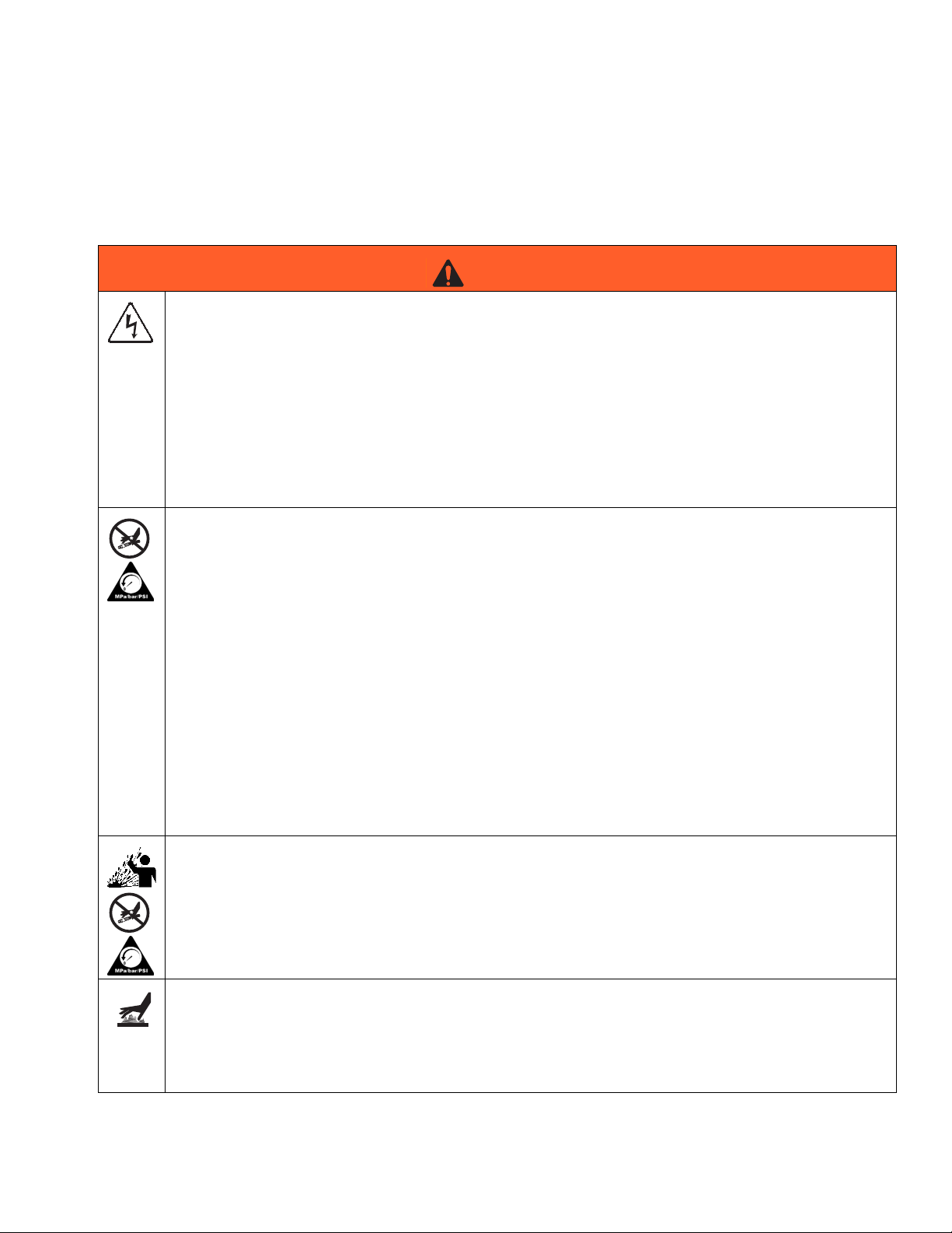
Warnings
The following warnings are for the setup, use, grounding, maintenance, and repair of this equipment. The exclamation point symbol alerts you to a general warning and the hazard symbol refers to procedure-specific risk. Refer back
to these warnings. Additional, product-specific warnings may be found throughout the body of this manual where
applicable.
WARNING
ELECTRIC SHOCK HAZARD
The hoses must be grounded. Improper grounding, set-up or usage of the hoses can cause electric
shock.
• Turn off and disconnect power before disconnecting before installing or servicing hoses.
• Connect to grounded power source.
• All electrical wiring must be done by a qualified electrician and comply with all local codes and
regulations.
• Never cut or puncture a hose cover.
• Do not expose to rain. Store indoors.
SKIN INJECTION HAZARD
High-pressure fluid from hose leaks, or ruptured components will pierce skin. This may look like just a
cut, but it is a serious injury that can result in amputation. Get immediate surgical treatment.
• Inspect hose before each use for cuts, bulges, kinks or any other damage.
• Replace hoses proactively at regular intervals based on your operating conditions.
• Replace damaged hose immediately.
• Tighten all fluid connections before operating the equipment.
• Keep clear of leaks.
• Do not stop or deflect leaks with your hand, body, glove, or rag.
• Never exceed hose Maximum Pressure or Temperature ratings.
• Only use chemicals that are compatible with wetted parts. See Technical Data in this manual.
Read MSDSs and fluid and solvent manufacturer’s recommendations.
• Follow the Pressure Relief Procedure when you stop spraying and before cleaning, checking, or
servicing equipment.
THERMAL EXPANSION HAZARD
Fluids subjected to heat in confined spaces, including hoses, can create a rapid rise in pressure due to
the thermal expansion. Over-pressurization can result in equipment rupture and serious injury.
• Open a valve to relieve the fluid expansion during heating.
• Replace hoses proactively at regular intervals based on your operating conditions.
BURN HAZARD
Equipment surfaces and fluid that’s heated can become very hot during operation. To avoid severe
burns:
• Do not touch hot fluid or equipment.
3A0237L 11
Page 12
Warnings
WARNING
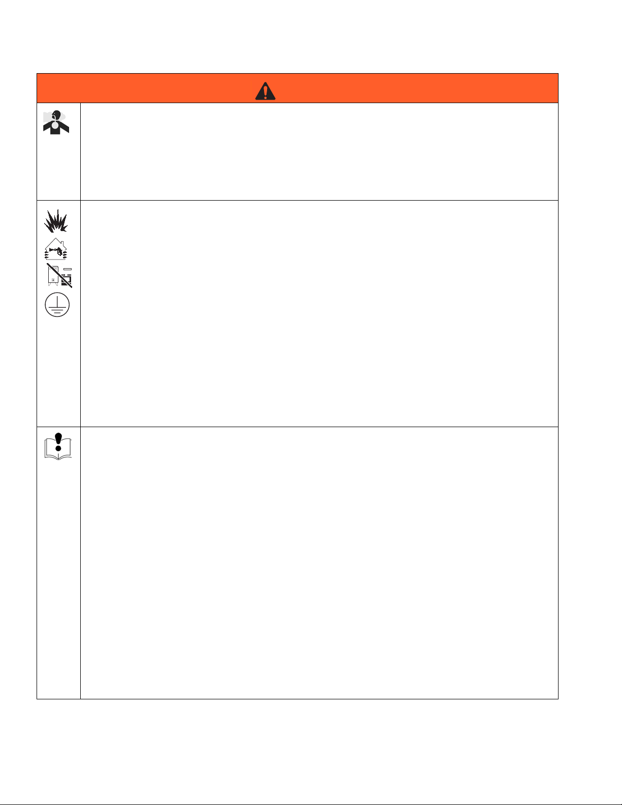
TOXIC FLUID OR FUMES HAZARD
Toxic fluids or fumes can cause serious injury or death if splashed in the eyes or on skin, inhaled, or
swallowed.
• Read MSDSs to know the specific hazards of the fluids you are using.
• Store hazardous fluid in approved containers, and dispose of it according to applicable guidelines.
• Always wear chemically impermeable gloves when spraying, dispensing, or cleaning equipment.
FIRE AND EXPLOSION HAZARD
Flammable fumes, such as solvent and paint fumes, in work area can ignite or explode. To help
prevent fire and explosion:
• Use equipment only in well ventilated area.
• Eliminate all ignition sources; such as pilot lights, cigarettes, portable electric lamps, and plastic
drop cloths (potential static arc).
• Keep work area free of debris, including solvent, rags and gasoline.
• Do not plug or unplug power cords, or turn power or light switches on or off when flammable fumes
are present.
• Ground all equipment in the work area. See Grounding instructions.
• Use only grounded hoses.
• Hold gun firmly to side of grounded pail when triggering into pail.
• If there is static sparking or you feel a shock, stop operation immediately. Do not use equipment
until you identify and correct the problem.
• Keep a working fire extinguisher in the work area.
EQUIPMENT MISUSE HAZARD
Misuse can cause death or serious injury.
• Do not operate the unit when fatigued or under the influence of drugs or alcohol.
• Do not exceed the maximum working pressure or temperature rating of the lowest rated system
component. See Technical Data in all equipment manuals.
• Use fluids and solvents that are compatible with equipment wetted parts. See Technical Data in all
equipment manuals. Read fluid and solvent manufacturer’s warnings. For complete information
about your material, request MSDS from distributor or retailer.
• Do not leave the work area while equipment is energized or under pressure. Turn off all equipment
and follow the Pressure Relief Procedure when equipment is not in use.
• Check equipment daily. Repair or replace worn or damaged parts immediately with genuine
manufacturer’s replacement parts only.
• Do not alter or modify equipment.
• Use equipment only for its intended purpose. Call your distributor for information.
• Route hoses and cables away from traffic areas, sharp edges, moving parts, and hot surfaces.
• Do not kink or over bend hoses or use hoses to pull equipment.
• Keep children and animals away from work area.
• Comply with all applicable safety regulations.
12 3A0237L
Page 13

Warnings
WARNING
PERSONAL PROTECTIVE EQUIPMENT
You must wear appropriate protective equipment when operating, servicing, or when in the operating
area of the equipment to help protect you from serious injury, including eye injury, hearing loss, inhalation of toxic fumes, and burns. This equipment includes but is not limited to:
• Protective eyewear, and hearing protection.
• Respirators, protective clothing, and gloves as recommended by the fluid and solvent manufacturer.
3A0237L 13
Page 14

Important Two-Component Material Information
Important Two-Component Material Information
Isocyanate Conditions
Spraying or dispensing materials containing
isocyanates creates potentially harmful mists, vapors,
and atomized particulates.
Read material manufacturer’s warnings and material
MSDS to know specific hazards and precautions
related to isocyanates.
Prevent inhalation of isocyanate mists, vapors, and
atomized particulates by providing sufficient
ventilation in the work area. If sufficient ventilation is
not available, a supplied-air respirator is required for
everyone in the work area.
To prevent contact with isocyanates, appropriate
personal protective equipment, including chemically
impermeable gloves, boots, aprons, and goggles, is
also required for everyone in the work area.
Material Self-ignition
Some materials may become self-igniting if applied
too thickly. Read material manufacturer’s warnings
and material MSDS.
Keep Components A and B
Moisture Sensitivity of Isocyanates
Isocyanates (ISO) are catalysts used in two component
foam and polyurea coatings. ISO will react with moisture
(such as humidity) to form small, hard, abrasive crystals,
which become suspended in the fluid. Eventually a film
will form on the surface and the ISO will begin to gel,
increasing in viscosity. If used, this partially cured ISO
will reduce performance and the life of all wetted parts.
NOTE: NOTE: The amount of film formation and rate of
crystallization varies depending on the blend of ISO, the
humidity, and the temperature.
To prevent exposing ISO to moisture:
• Always use a sealed container with a desiccant
dryer in the vent, or a nitrogen atmosphere. Never
store ISO in an open container.
• Keep the ISO lube pump reservoir (if installed) filled
with Graco Throat Seal Liquid (TSL
The lubricant creates a barrier between the ISO and
the atmosphere.
• Use moisture-proof hoses specifically designed for
ISO, such as those supplied with your system.
• Never use reclaimed solvents, which may contain
moisture. Always keep solvent containers closed
when not in use.
• Never use solvent on one side if it has been contaminated from the other side.
• Always lubricate threaded parts with ISO pump oil
or grease when reassembling.
™
), Part 206995.
Separate
Foam Resins with 245 fa Blowing Agents
Some foam blowing agents will froth at temperatures
Cross-contamination can result in cured material in
fluid lines which could cause serious injury or
damage equipment. To prevent cross-contamination
of the equipment’s wetted parts, never interchange
component A (isocyanate) and component B (resin)
parts.
14 3A0237L
above 90°F (33°C) when not under pressure, especially
if agitated. To reduce frothing, minimize preheating in a
circulation system.
Page 15

Changing Materials
• When changing materials, flush the equipment multiple times to ensure it is thoroughly clean.
• Always clean the fluid inlet strainers after flushing.
• Check with your material manufacturer for chemical
compatibility.
• Most materials use ISO on the A side, but some use
ISO on the B side.
• Epoxies often have amines on the B (hardener)
side. Polyureas often have amines on the B (resin)
side.
A and B Components
A and B Components
IMPORTANT!
Material suppliers can vary in how they refer to plural
component materials.
Be aware that when standing in front of the manifold on
proportioner:
• Component A (Red) is on the left side.
• Component B (Blue) is on the right side.
For all machines:
• The A (Red) side is intended for ISO, hardeners,
and catalysts.
• If one of the materials being used is moisture-sensitive, that material should always be in the A (Red)
side.
• The B (blue) side is intended for polyols, resins, and
bases.
NOTE: For ratios higher than 1:1, the higher volume
is typically the B (Blue) side.
3A0237L 15
Page 16

Installation
Installation
Description
The heated hose maintains proper fluid temperature
while dispensing.
Fluid hoses are marked with red tape for ISO/hardener/minor volume side, blue tape for RES/resin/major
volume side. Fittings have different sized threads to prevent incorrect connection, which can cause fluid crossover and permanently damage the hose.
Hoses are 5 ft (1.5 m), 10 ft (3 m), 25 ft (7.6 m), and 50 ft
(15.2 m) long. The whip hose is 5 ft (1.5 m) or 10 ft (3 m)
long.
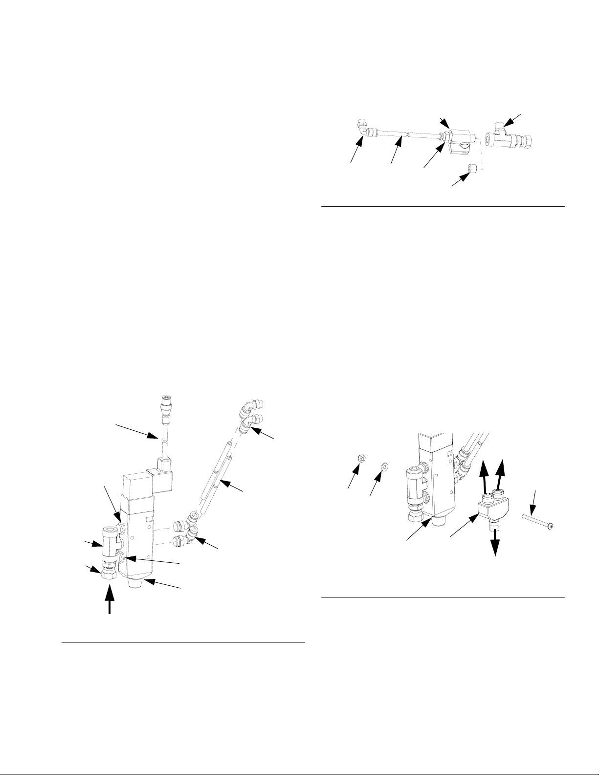
Connect Whip Hose to Gun or
Tighten
F
IG. 1: Fusion Gun
Tighten
Tighten
Gun Manifold
NOTE: For best whip hose flexibility, assemble whip
hose to gun or gun manifold as instructed.
1. Assemble A and B component hoses to gun or gun
manifold fittings as shown in F
2. If applicable, assemble signal cable (E1) and air
hose to gun or gun manifold fittings.
3. Tighten fittings to A and B component hoses.
Ensure hose remains flat after fittings are tightened.
Loosen and retighten fittings as necessary to eliminate any torque on hoses. This will help achieve a
flat profile on the hose.
NOTE: Use chemical connection kit (153) on all MD2
valves. See F
4. For MD2 valves with 255208 and 255249 and both
EP Gun models, connect the signal cable (E1) from
the applicator to the whip hose signal cable (3b).
5. See applicator manual for complete setup instructions.
IG. 2.
IG. 1 and FIG. 2.
153c
153a
F
IG. 2: MD2 Valve Kit 24D501
B Side Hose
3b
E1
A Side Hose
153b
153a
r_24d501_3a0237_1a
16 3A0237L
Page 17

Installation
Connect Heated Hoses
1. Lay heated hoses end to end, matching the color
coding. Red for component A (ISO), blue for component B (RES).
B
A
FIG. 3
TI14731a
4. Connect air hoses (C).
Single Heat Zone with A and B Heated Hose
D
C
TI14733a
Dual Heat Zone with A and B Heated Hose
D
C
TI15097a
D
Single Heat Zone with A or B Heated Hose
2. Connect fluid hoses (A, B).
3. Connect signal cables (13).
B
A
TI14732a
F
13
IG. 4
NOTE: Do not connect the main air supply to the air
hose at this time.
D
D
FIG. 5
5. Connect electrical wires (D).
a. Ensure electrical wires ends are 5/8 in.
(0.625mm) long. If they are not, use a sharp
scissors to strip all four wire ends to the correct
length. See Strip Length Gauge for correct
length.
Strip Length
C
TI15140a
This illustration is not to scale.
IG. 6
F
3A0237L 17
5/8 in.
(0.625 mm)
TI9733a
Page 18

Installation
NOTE: Be careful not to cut or nick copper strands.
If more than five strands are cut or nicked, trim wire
and re-strip.
New hoses are pre-stripped at correct length;
remove insulation to expose bare wire.
a. Ensure strip length is correct by fitting ferrule
over exposed wire. Ferrule should be flush with
wire end. See F
IG. 7.
NOTE: On some older heated hoses wire insulation
will not fit inside ferrule insulator. In these cases,
use scissors to split and remove ferrule insulator.
b. If wire is short of ferrule end, adjust strip length
accordingly. If bare wire is protruding from ferrule, trim flush to ferrule end. See F
IG. 7.
Incorrect
Correct
a. Insert one wire from heated hose into connec-
tor. Ensure that ferrule is mating with connector
insert. See F
IG. 9.
TI9770A
FIG. 9: Insert Wire and Setscrew
b. Thread in setscrew and use hex wrench to
torque setscrew to 60 in-lbs (6.78 N•m).
NOTE: To reach approximately 60 in-lbs (6.78 N•m),
complete 4.5 revolutions with hex wrench after setscrew comes in contact with ferrule.
Incorrect
TI9768a
F
IG. 7
c. Remove ferrule and apply oxide inhibitor to bare
wire. See F
d. Reinsert wire in ferrule and apply more oxide
inhibitor to ferrule and wire end.
IG. 8
F
6. Pair electrical wires as follows: A-Hose to A-Hose;
B-Hose to B-Hose.
NOTE: When connecting first hose section to proportioner, wire pairing does not make a difference.
IG. 8.
TI9769A
TI9779A
F
IG. 10: Torque Setscrew
c. Insert remaining wire from pair into connector;
ensure proper insertion depth. Thread setscrew
and torque to 60 in-lbs (6.78 N•m); see sub-step
B. See F
IG. 9 and FIG. 10.
d. Repeat sub-steps A through C for remaining
wire pair.
e. Re-torque all setscrews to 60 in-lbs (6.78 N•m).
NOTE: When torqued to 60 in-lbs (6.78 N•m) setscrews will be approximately flush with connector.
See F
IG. 11.
18 3A0237L
Page 19

f. Insert cap plugs over setscrews. See FIG. 11.
Cap plugs
Setscrews
TI9771A
F
IG. 11
g. Wrap connector and wire on each side of con-
nector in black electrical tape to help seal out
moisture. Ensure 1 in. (25.4 mm) of wire on
each side of connector is wrapped.
7. Connect cables (F). Leave slack (G) in cables as
stress relief to prevent cable failure.
Installation
F
TI14734a
F
IG. 12
G
8. Repeat for additional hoses.
9. See Connect FTS and Heated Whip Hose, page
20.
3A0237L 19
Page 20

Installation
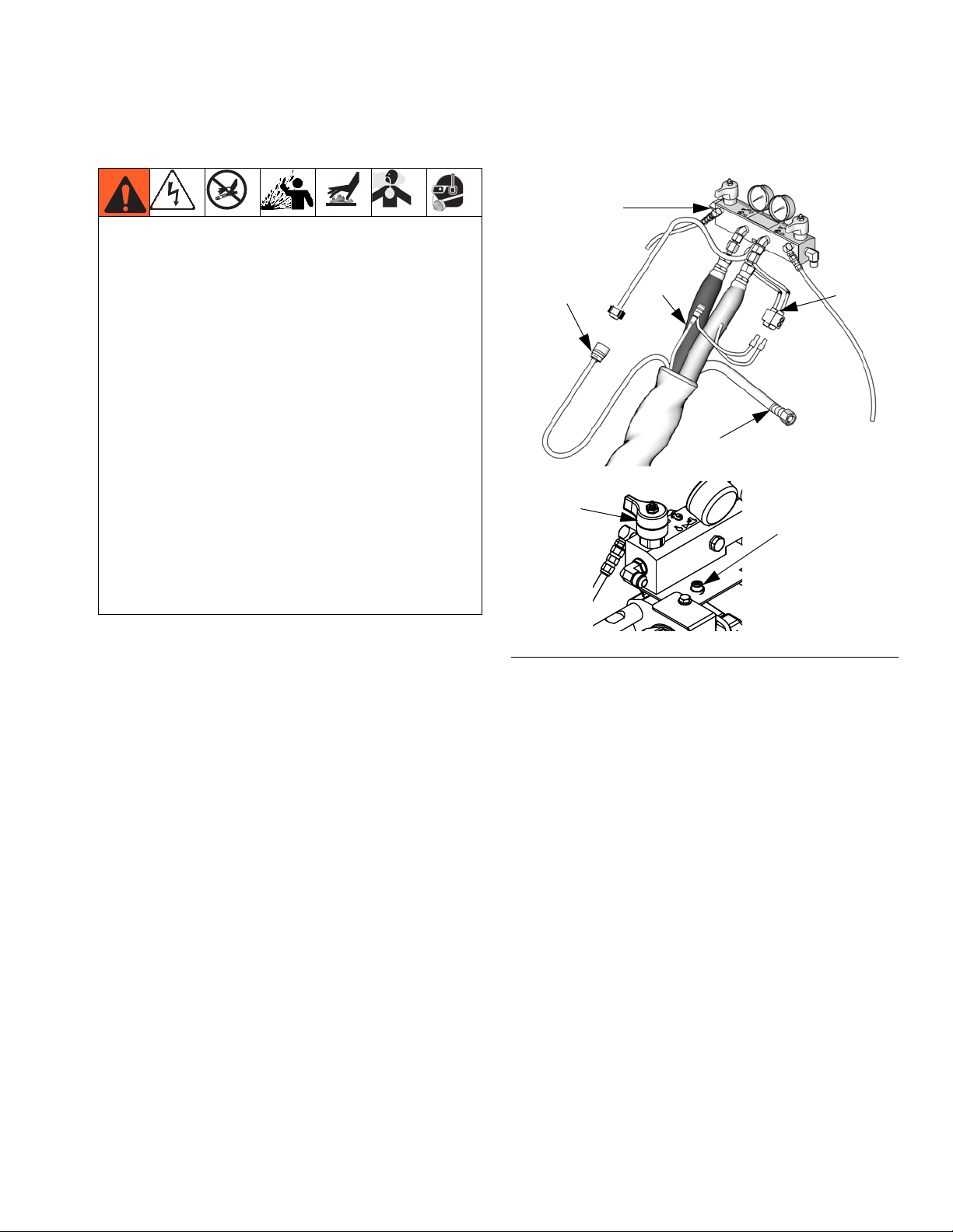
Connect FTS and Heated Whip Hose
NOTICE
To prevent damage to probe, do not kink or excessively bend hose. Do not coil hose tighter than the
minimum bend radius of 3 ft (0.9 m). Do not subject
hose to excessive weight, impact, or other abuse.
1. For Single Zone Heat:
Carefully extend FTS probe (H) into the hose section from the proportioner. Do not bend or kink
probe. Insert in component A (red) side of main
hose for foam or polyurea systems.
For Dual Zone Heat:
Carefully extend FTS probe (H) into the hose sections from the proportioner. Do not bend or kink
probe. Insert in component A (red) and component
B (blue) side of main hose for foam or polyurea systems.
2. Connect FTS (J) to whip hose (W).
Single Zone Heat
R
3. Connect whip hose ground wire (K) to ground screw
on underside of FTS.
4. Connect fluid hoses to FTS (J).
NOTE: To use 1/2 in. (13 mm) ID fluid hoses, remove
the adapters from the proportioner fluid manifold
and install them in the FTS swivel inlets.
5. Connect electrical connectors (D).
6. Connect air hose (C) to whip air hose (L) or see
Connect Solenoid Kit on page 21 for installation
instructions.
7. Connect hose assembly cable (F) to FTS cable (R).
Leave slack (G) in cables as stress relief, to prevent
cable failure.
8. See Check Hoses for Leaks, page 22.
D
K
J
B
To Gun
G
To Proportioner
Dual Zone Heat
G
To Proportioner
FIG. 13: FTS Connections
F
W
A
B
A
F
D
R
B
A
H
C
24
K
J
H
24
D
24D160 or 24D161, page 21
D
B
C
24D160 or 24D161, page 21
3b
L
ti14735a
To Gun
W
A
3b
D
L
ti14736b
20 3A0237L
Page 21
Installation
b
Connect Solenoid Kit
A solenoid kit is required for some applicators used with
Graco Metering Systems. See Individual Hoses on
page 5 to see which applicators require a solenoid kit.
NOTE: To ensure proper operation of valve, install
the solenoid kit within 15 ft (4.5 m) of the applicator.
The solenoid reaction time decreases if the solenoid
kit is farther away from the applicator. Ensure that
the scuff guard covers the solenoid if mounted
between the hose and whip hose.
1. Turn off all power to the system.
2. Apply anaerobic pipe sealant to pipe threads on
mufflers (205), tee fitting (202), and swivel fitting
(215). Connect to valve (201).
3. Connect elbow fittings (204), and wire harness
(206) to valve (201).
4. Connect air hose (C) to swivel fitting (215).
5. Connect two elbows (207) and tubing (212) to open
and closed ports on the applicator. See applicator
manual for port locations.
NOTE: Cut tubing (212) to desired length if necessary.
6. Install plug (203), or tube fitting (214) and ball valve
(213) in the other side of the tee fitting (202).
202
IG. 15
F
213
212207
214
203
r_24D161_3a0237B_2b
7. For solenoid kit 24D161: Connect elbow fitting (207)
and tubing (212) to the purge air port and tube fitting
(214). See applicator manual for port locations.
Connect Splitter
24D160 and 24D161 use a splitter (211) to allow the
Graco Metering System to dispense material from the
system controls.
1. Connect the splitter (211) to the valve (201) with
screw (208), washer (209), and nut (210).
2. Connect the hose communications cable (24) to the
single splitter (211) connection.
202
215
F
IG. 14
205
206
3. Connect the wire harness (206) and signal cable
(3b) from the whip hose to the splitter (211).
207
3b
206
208
212
210
209
211
24
r_24D160_3a0237b_1b
205
201
204
r_24D161_3a0237b_1
IG. 16
F
201
C
3A0237L 21
Page 22

Installation
4. For 24C757: Connect valve (201) to the B side
pump guard (GD) with screws (208) and washers
(209).
GD
206
209
208
F
IG. 17
201
r_24c352_3A0237_2a
5. Remove motor cover and connect solenoid cable
(206) to cable (2B).
2B
To use 1/2 in. (13 mm) ID fluid hoses, remove the adapters from the proportioner fluid manifold and install them
in the FTS swivel inlets.
M
N
P
TI14737b
FIG. 18
2. For spray guns, close fluid valves on gun fluid manifold. Remove manifold from gun, see gun manual.
Connect fluid whip hoses to manifold.
3. Check that all equipment is properly grounded. See
system operation manual.
4. Pressure check hose. See proportioner manual for
priming instructions. After all lines are free of air,
check for leaks. If there are leaks, relieve pressure
as instructed in proportioner manual. Tighten connections, then pressurize again to ensure leaks
have stopped. Relieve pressure.
6. For 24D160 and 24D161: Connect the valve (201)
between the last hose bundle and the whip hose
with zip ties (not supplied.) See F
IG. 13.
NOTE: To ensure proper operation of valve, install
the solenoid kit within 15 ft (4.5 m) of the applicator.
The solenoid reaction time decreases if the solenoid
kit is farther away from the applicator. Ensure that
the scuff guard covers the solenoid if mounted
between the hose and whip hose.
Check Hoses for Leaks
1. Grease with Fusion grease and connect fluid hoses
to proportioner fluid manifold (M). Red for hardener,
blue for resin. See F
NOTE: The manifold hose adapters (N,P) allow use
of 1/4 in. and 3/8 in. ID fluid hoses.
To check adapter tightness, torque as follows:
• A (red) side (N) to 20-25 ft-lb (27-34 N•m).
• B (blue) side (P) to 30-35 ft-lb (41-47 N•m).
IG. 18.
Protective Covering
1. Wrap all fluid hose connections with electrical tape.
TI14738a
F
IG. 19
2. Fold wire back on hose to ensure adequate strain
relief. Wrap all electrical connections and cable connections with electrical tape to protect them from
pulling apart and abrasion.
3. Install protective cover, or wrap hose bundle with
duct tape to protect foam.
4. For hoses that include a protective scuff cover,
unroll excess cover over hose and electrical connections. Tape securely.
22 3A0237L
Page 23
Operation
Do not operate a coiled hose. A coiled hose creates
uneven heat buildup which can result in hose rupture
and cause serious injury, including fluid injection.
Maximum hose operating temperature is 180°F
(82°C). If using hose without an FTS, measure hose
temperature to ensure it does not exceed 180°F
(82°C).
Hose must be properly supported to avoid excessive
strain due to weight, bending, or sharp edges.
Operation
Single Heat Zone Shown
M
13
DF
Fluids subjected to heat in confined spaces, including
hoses, can create a rapid rise in pressure due to the
thermal expansion. Over-pressurization can result in
equipment rupture and serious injury.
• Open a valve to relieve the fluid expansion during
heating.
• Replace hoses proactively at regular intervals
based on your operating conditions.
1. Connect air hose (C) to main air supply if equipped.
2. Connect electrical connectors (D) to connector from
fluid manifold (M) or accessory control box. See ,
page 16. Connect hose cable (F) to cable from proportioner fluid manifold (M) or accessory control
box. Connect signal cable (24) to connector behind
the proportioner fluid manifold (M).Wrap connections with electrical tape.
FIG. 20
M
C
TI14737b
(24) connector
3A0237L 23
Page 24

Maintenance
Maintenance
1. Before disconnecting or repairing hoses, relieve all
fluid pressure and shut off electrical power to proportioner. See system operation manual.
2. Be sure fluid is cool before disconnecting hoses.
Clean Orifice
Only for MD2 Valve using Orifice Block Kit 24E505 and
an orifice.
NOTE: 24E505 does not come with an orifice. See
on page 39 for orifice part numbers.
1. Follow Pressure Relief Procedure in MD2 valve
manual.
Instructions for Replacing Individual A or B Hose
1. Before disconnecting hoses, relieve all fluid pressure and shut off electrical power to proportioner.
See system operation manual.
2. Disconnect electrical wire from connectors (5). Disconnect fluid hose and remove from bundle.
3. For whip hose bundles, see Bundle Individual
Whip Hoses on page 26.
4. For hose bundles, see Bundle Individual Heated
Hoses on page 28.
2. Use 5/16 in. nut driver to remove orifices.
NOTICE
To prevent cross-contamination of the orifices do
not interchange A component and B component
parts. The A component orifice is marked with an
A.
3. Remove cap from orifice.
NOTE: The cap is held in place with reverse threads.
4. Remove needle from orifice. Thoroughly inspect all
o-rings and replace if necessary.
5. If necessary, use drill bit that is the same size as the
orifice to drill out the orifice. Orifice size is marked
on the orifice.
6. Liberally lubricate all o-rings.
7. Reassemble in reverse order. Torque orifices into
fluid housing to 20-30 in-lb (2.26-3.39 N•m).
24 3A0237L
Page 25

Maintenance
3A0237L 25
Page 26

Maintenance
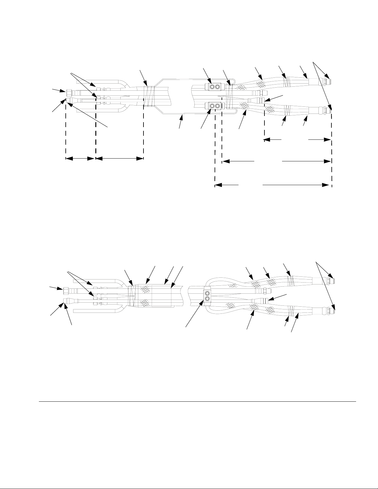
Bundle Individual Whip Hoses
Individual whip hoses must be bundled with scuff guards
and air and signal cables. Follow the instructions below
to bundle single and dual heat zone whip hose bundles.
See F
IG. 21 on page 27.
1. Lay out the A and B material hoses with the male fittings at the same end of the bundle.
2. Lay out the air hose (3) with the male fitting at the
same end as the male fittings of the material hoses.
NOTE: The female fitting of the air hose should be 6
in. (152.4 mm) beyond the female fitting of the material hoses.
3. Lay out the signal cable (4) with the female end of
the signal cable at the same end as the male ends
of the material hoses.
NOTE:
• The male sign cable connector (4) should be 6
in. beyond the female ends of the material
hoses.
• Use electrical tape (8) to secure position of signal cable 10 in. (254 mm) back from the end of
the material hose.
4. Connect Electrical Connectors.
For Single Zone Heated Whip Hose Bundles:
a. Place one 6 AWG electrical connector (5) 24 in.
(609.6 mm) from the male material hose fittings.
5. Apply scuff guard (10) on each individual material
hose up to the electrical connector (5).
6. Use red electrical tape (12) to secure the scuff
guard (10) on the red material hose.
7. Use blue electrical tape (13) to secure the scuff
guard (10) on the blue material hose.
8. Use electrical tape and temporarily tape the hose
and cable ends together.
9. Feed the scuff guard (4) over the male material
hose fittings.
10. Use black electrical tape (8) and secure at least 3 in.
(76.2 mm) of scuff guard (4) next to the electrical
connector (5) on side with male material hose fittings.
NOTE: Ensure no foam insulation is exposed on
either material hose.
11. Fold the scuff guard (4) over itself and feed the
remaining scuff guard over the entire length of the
bundle.
12. Leave excess scuff guard (4) loose on the end with
the female material fittings.
13. Remove electrical tape securing the hose and cable
ends together.
14. Apply warning label (10) in the center of the bundle.
Secure edges with black electrical tape.
b. Connect the 6 AWG wire from each material
hose to the electrical connector (5).
c. Use black electrical tape (8) to secure the con-
nector to the hose bundle.
For Dual Zone Heated Whip Hose Bundles:
a. Place two 6 AWG electrical connectors (5) 24
in. (609.6 mm) from the male material hose fittings.
b. Unlace the 6 AWG wire from each material
hose, trim back the wire, and connect to the
electrical connector (5).
c. Use black electrical tape (8) to secure both con-
nectors (5) to the correct material hose.
26 3A0237L
Page 27
Maintenance
Dual Heat Zone Heated Whip Hose Bundle
female fittings
3
4
6 in.
(152.4 mm)
male
connector
10 in.
(254 mm)
8
4
5
5
8 10
10
27 in.
(685.8 mm)
13
female
connector
12
16 in.
(406.4 mm)
24 in.
(609.6 mm)
male fittings
2
B Side
A Side
1
Single Heat Zone Heated Whip Hose Bundle
10
female fittings
3
4
male
connector
FIG. 21: Whip Hose Bundles
8
4
8
5
10
10
13
2
female
connector
12
1
male fittings
B Side
A Side
3A0237L 27
Page 28

Maintenance
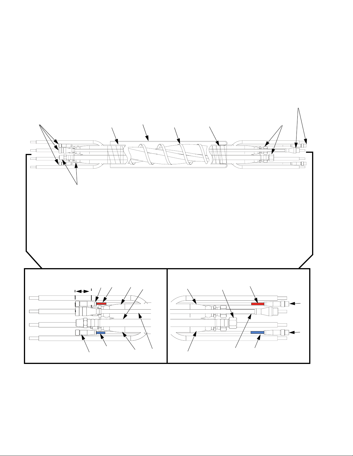
Bundle Individual Heated Hoses
Individual hoses must be bundled with a scuff guard,
FTS cable(s), and air and signal cables.Follow the
instructions below to bundle individual heated hoses for
dual and single zone heat.
See F
IG. 22 on page 29.
1. Lay out the A and B material hoses with the male fittings at the same end of the bundle.
2. Lay out the air hose (23) with the male fitting at the
same end as the male fittings of the material hoses.
3. Lay out the signal cable (24) and FTS cable(s) (25)
with the female end of the cables at the same end
as the male fittings of the material hoses.
NOTE:
• All signal cable connectors (24) should be 2 in.
(50.8 mm) beyond the male fittings of the material hoses.
• Use electrical tape (29) to secure position of signal cable 10 in. (254 mm) back from the end of
the material hose.
4. Wrap FTS Cables.
7. Use electrical tape and temporarily tape the hose
and cable ends together.
8. Feed the scuff guard (26) over the female material
hose fittings.
9. Use black electrical tape (29) and tape the scuff
guard (26) down 10 in. from the female fittings on
the material hoses. Tape at least 3 in. (76.2 mm) of
scuff guard (26).
NOTE: Ensure no foam insulation is exposed on
either material hose.
10. Fold the scuff guard (26) over itself and feed the
remaining scuff guard over the entire length of the
bundle.
11. Leave excess scuff guard (26) loose on the end with
the male material fittings.
12. Remove electrical tape securing the hose and cable
ends together.
13. Apply warning label (31) in the center of the bundle.
Secure edges with black electrical tape (29).
NOTICE
To heat material correctly, ensure that the red electrical
tape is on the A side FTS cable and the blue electrical
tape is on B side FTS cable.
a. Wrap each end of one FTS cable (25) with red
electrical tape (32). This FTS cable will correspond with the A material hose.
b. For Dual Zone Heat Only: wrap each end of the
other FTS cable (25) with blue electrical tape
(33). This FTS cable will correspond with the B
material hose.
5. Carefully twist the material hoses, air hose (23), and
cables throughout the entire bundle with a 24 in
(609.6 mm) maximum pitch.
NOTE: Do not twist 5 ft and 10 ft hose bundle
lengths.
6. Tightly wrap the bundle with lace (28) with an 8 in.
maximum pitch. Use black electrical tape to stop the
lacing 10 in. (254 mm) from the material fittings on
each end of the hoses.
28 3A0237L
Page 29

Dual Heat Zone Heated Hose Bundle Shown
Maintenance
male connectors
female connectors
2 in.
50.8 mm)
A Side
male fittings
32
21
2325
26
28 2929
4 in.
101.6 mm)
3 in.
(76.2 mm)
21
1
1 in.
(25.4 mm)
10 in.
(254 mm)
Machine End
23
32
female fittings
18 in.
457.2 mm)
19 in.
(482.6 mm)
A Side
B Side
25
1
No exposed foam permitted.
FIG. 22: Heated Hose Bundles
33
22
24
22
24
25
25
B Side
33
3A0237L 29
Page 30

Parts
Parts
Whip Hoses
NOTE: A FTS assembly must connect the heated hose and whip hose. See page 35.
Dual Heat Zone Heated Whip Hose
8
3
4
Single Heat Zone Heated Whip Hose
8
3
4
10
5
4
5
8
8 10
10
10
13
12
13
2
2
B Side
A Side
1
B Side
4
5
30 3A0237L
10
12
1
A Side
Page 31

Parts
Heated Whip Hoses
Ref.
No. Part No. Description Qty.
Common Parts
Ref.
12‡ TAPE, electrical; red 1
13‡ TAPE, electrical; blue 1
No. Part No. Description Qty.
4★ SCUFF GUARD; 1.75 in. dia.; see
varied parts table for length
7▲✖ 15B679 LABEL, safety; A hose, B Hose,
and whip hose, English
▲✖ 16M219 LABEL, safety; A hose, B Hose,
and whip hose, Spanish/French
8‡ TAPE, electrical; black 1
9 120542 BAG, polyethylene; not shown 2
10✿ SCUFF GUARD; 1.25 in. dia.; see
varied parts table for length
1
▲ Replacement Danger and Warning labels, tags, and
3
3
cards are available at no cost.
✖ Not shown.
‡ Purchase locally.
✿ Order 24E961for replacement scuff guard. Contains
2
30 ft (9 m) of braided polyester mesh.
★ Order 24E954 replacement scuff guard. Contains
200 ft (60.9 m) of braided polyester mesh.
Varied Par ts
Reference Number and Description
✖
12345
Hose
Assy
Stainless Steel Dual Heat Zone
24D193 5 (1.5) See Heated
24D194 10 (3) 24D171 10 (3) 261821
24D750 25 (7.6) 24D169 33 (10) 261821
24D751 50 (15.2) 24D171 56 (17) 261821
Carbon Steel Dual Heat Zone
24D195 5 (1.5) See Heated
24D196 10 (3) 24D171 10 (3) 261821
24D752 25 (7.6) 24D169 33 (10) 261821
24D753 50 (15.2) 24D171 56 (17) 261821
Carbon Steel Single Heat Zone
24D192 10 (3) See Heated
24D822 10 (3) 24D171 10 (3) 261821 (1) 261181
24E970 10 (3) 24D171 10 (3) 261821 (1)
24E971 10 (3) 24D171 10 (3) 261821 (1)
Qty.111 2 (1)1
Length
ft (m)
Red (A) Hose Blue (B) Hose
See Heated
Whip Hose,
page 4.
Whip Hose,
page 4.
Whip Hose,
page 4.
Whip Hose,
page 4.
See Heated
Whip Hose,
page 4.
See Heated
Whip Hose,
page 4.
Air Hose and
Signal Cable
Kit
24D169 9 (2.7) 261821
24D169 9 (2.7) 261821
24D171 10 (3) 261821 (1)
Scuff Guard
Length
ft (m)
Electrical
Connector
6
Connector
Splice
Air Hose and Signal Cable Kits (3)
Reference Number and Description
3a
Kit
24D169 24E953 24E900
24D171 15B280 24E899
Qty.1 1
3A0237L 31
Air Hose 5 Pin Signal Cable
3b
Page 32
Parts
Heated Hose Bundles
NOTE: A FTS assembly must connect the heated hose and whip hose. See page 35.
Dual Heat Zone Heated Hose Bundle Shown
male connectors
female connectors
2 in.
50.8 mm)
A Side
male fittings
32
21
26
28 2929
Machine End
2325
21
23
female fittings
32
A Side
5
5
B Side
32 3A0237L
25
33
22
24
22
24
33
B Side
Page 33

Dual Zone Heated Hose Bundles
Common Parts
Parts
Ref.
No. Part No. Description Qty.
26✿ SCUFF GUARD; 1.75 in. dia.; see
varied parts table for length
▲ Replacement Danger and Warning labels, tags, and
cards are available at no cost.
1
✿ Order 24E954 for replacement scuff guard. Contains
200 ft (60.9 m) of braided polyester mesh.
27 261821 CONNECTOR, electrical 2
29‡ TAPE, electrical; black 1
30✖ 120542 BAG, polyethylene 2
31▲✖ 15B679 LABEL, safety; A hose, B Hose,
✖ Not shown.
‡ Purchase locally.
3
and hose bundle, English
▲✖ 16M219 LABEL, safety; A hose, B Hose,
3
and hose bundle, Spanish/French
32‡ TAPE, electrical; red 1
33‡ TAPE, electrical; blue 1
Varied Par ts
Reference Number and Description
21 22
Hose
Assy
24D108 5 (1.5) See Heated
24D109 10 (3) 15B280 24E899 24E895 10 (3) 18 (457.2)
24D110 25 (7.6) 24F179 24E898 24E894 33 (10) 45 (1143)
24D111 50 (15.2) 15B290 24E897 24E893 56 (17) 90 (2286)
24D112 5 (1.5) 24E953 24E900 24E896 9 (2.7)
24D113 10 (3) 15B280 24E899 24E895 10 (3) 18 (457.2)
24D114 25 (7.6) 24F179 24E898 24E894 33 (10) 45 (1143)
24D115 50 (15.2) 15B290 24E897 24E893 56 (17) 90 (2286)
24D116 5 (1.5) 24E953 24E900 24E896 9 (2.7)
24D117 10 (3) 15B280 24E899 24E895 10 (3) 18 (457.2)
24D118 25 (7.6) 24F179 24E898 24E894 33 (10) 45 (1143)
24D119 50 (15.2) 15B290 24E897 24E893 56 (17) 90 (2286)
24D120 5 (1.5) 24E953 24E900 24E896 9 (2.7)
24D121 10 (3) 15B280 24E899 24E895 10 (3) 18 (457.2)
24D122 25 (7.6) 24F179 24E898 24E894 33 (10) 45 (1143)
24D123 50 (15.2) 15B290 24E897 24E893 56 (17) 90 (2286)
Qty.111121see above
Length
ft (m)
Red (A) Hose Blue (B) Hose Air Hose
See Heated
Hose Bundle
Part Numbers,
page 3.
Hose Bundle
Part Numbers,
page 3.
23 24 25 26 28
Scuff
5 Pin
Signal
Cable
24E953 24E900 24E896 9 (2.7)
FTS
Cable
Guard
Length
ft (m)
Tie Hose
Lacing
Length
in. (mm)
3A0237L 33
Page 34

Parts
Single Zone Heated Hose Bundles
Common Parts
Ref.
No. Part No. Description Qty.
26✿ SCUFF GUARD; 1.75 in. dia.; see
varied parts table for length
▲ Replacement Danger and Warning labels, tags, and
cards are available at no cost.
1
✿ Order 24E954 for replacement scuff guard. Contains
200 ft (60.9 m) of braided polyester mesh.
27 261821 CONNECTOR, electrical 1
29‡ TAPE, electrical; black 1
30✖ 120542 BAG, polyethylene 2
31▲✖ 15B679 LABEL, safety; A hose, B Hose,
✖ Not shown.
‡ Purchase locally.
3
and hose bundle, English
▲✖ 16M219 LABEL, safety; A hose, B Hose,
3
and hose bundle, Spanish/French
32‡ TAPE, electrical; red 1
33‡ TAPE, electrical; blue 1
Varied Par ts
Reference Number and Description
21 22
Hose
Assy
24D124 25 (7.6) See Heated
24D125 50 (15.2) 15B280 24E899 24E895 56 (17) 90 (2286)
24D126 25 (7.6) 24F179 24E898 24E894 33 (10) 45 (1143)
24D127 50 (15.2) 15B290 24E897 24E893 56 (17) 90 (2286)
24D129 50 (15.2) 15B280 24E899 24E895 56 (17) 90 (2286)
24D131 50 (15.2) 15B290 24E897 24E893 56 (17) 90 (2286)
Qty.111111see above
Length
ft (m)
Red (A) Hose Blue (B) Hose Air Hose
See Heated
Hose Bundle
Part Numbers,
page 3.
Hose Bundle
Part Numbers,
page 3.
23 24 25 26 28
Scuff
5 Pin
Signal
Cable
24E953 24E900 24E896 33 (10) 45 (1143)
FTS
Cable
Guard
Length
ft (m)
Tie Hose
Lacing
Length
in. (mm)
34 3A0237L
Page 35
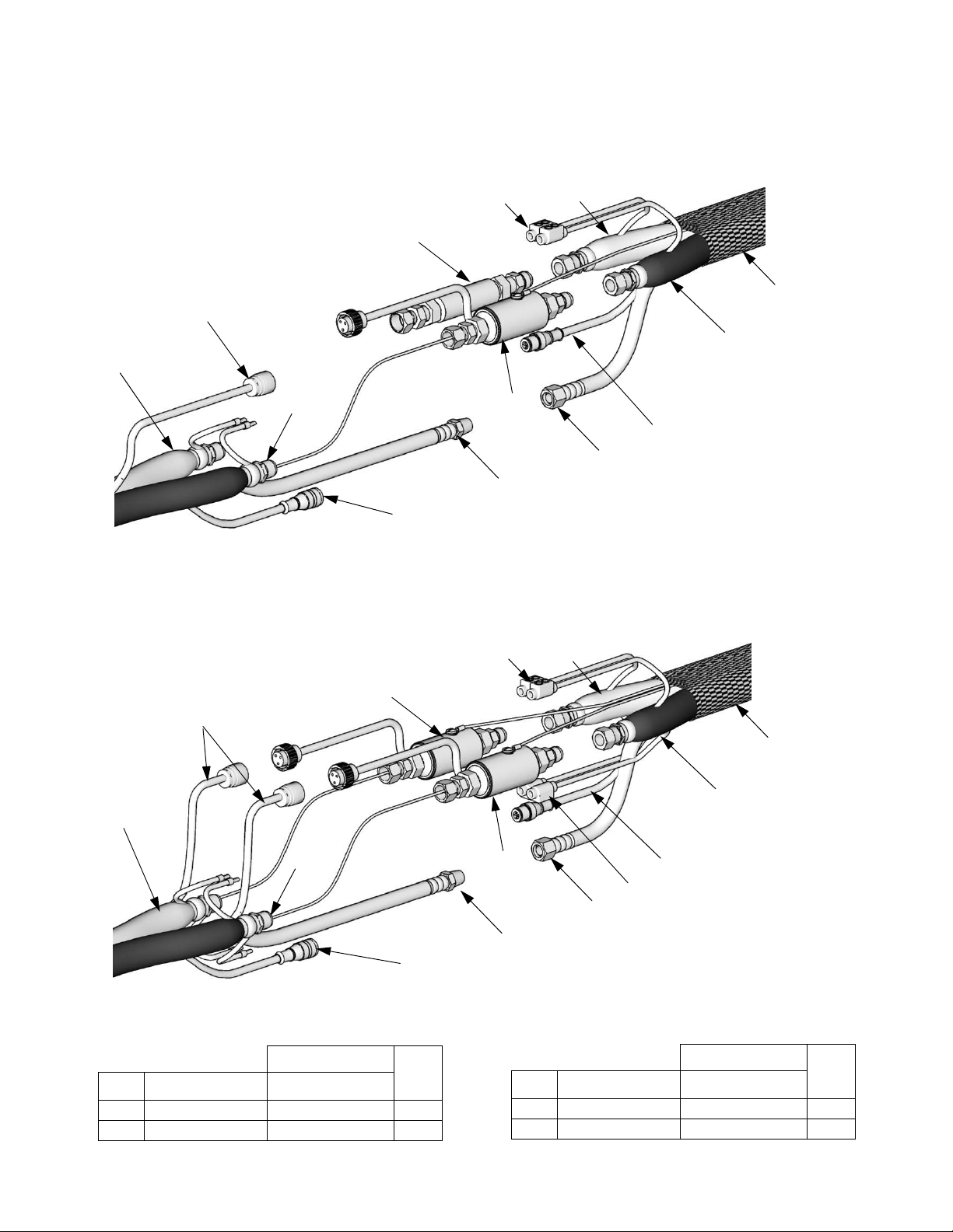
Using Fluid Temperature Sensors For Single Heat Zones
258758 Carbon Steel Fluid Temperature Sensor
Fluid Temperature Sensor
27
52
2
Parts
Whip Hose
Heated Fluid Hose
25
22
21
51
3b
3a
23
24
Using Fluid Temperature Sensors for Dual Heat Zones
258757 Stainless Steel Fluid Temperature Sensor
2
25
Fluid Temperature Sensors
52
27
10
1
TI1435a
Whip Hose
10
1
22
21
51
3b
27
3a
23
24
TI14736b
Heated Fluid Hose
FTS Kits
Dual Heat Zones
Description
FTS, sensor, red 24F393 1
51
FTS, sensor, blue 24F392 1
52
3A0237L 35
258756
Qty.Ref.
Description
FTS, sensor, red 24F393 1
51
52 COUPLER 16C806 1
Single Heat Zones
258758
Qty.Ref.
Page 36

Parts
15F144 Hose Wire Jumper
Use the 15F144 Hose Wire Jumper to heat only the
major volume hose, in a wide ratio system.
To build one complete 50 ft single side heated hose bundle, order the following parts:
Ref. Part Description Qty
100 15F144 JUMPER, hose wire; includes
two 117789 electrical connectors; 50 ft (15.2 m) long
101 chart 2,
page 36
102 15B296 CABLE, FTS 1
103 15C517 HARNESS, hose jumper 1
104 261670 FLUID TEMPERATURE
105 pur-
chase
locally
106 pur-
chase
locally
Install as follows:
HOSE, resin, heated; 50 ft (15.2
m) minimum
SENSOR
HOSE, hardener, unheated; 50
ft (15.2 m) minimum; customer
supplied
CONNECTORS, fluid; as
required to complete assembly;
not shown
as
req’d
1. Wrap hose wire jumper (100) around resin hose
(101) in a spiral fashion.
2. Connect resin hose wire (101a) to other side of
Power-Lock
™
connector (100a); see page 16.
3. Wrap FTS cable (102) around resin hose (101) in a
spiral fashion.
4. Twist hoses (101 and 105) together to provide strain
1
1
relief.
5. Repeat steps 1-4 for each length of hose (101).
Connect hoses, electrical connectors, and cables;
see , page 16.
6. Install one -Lock connector (100a) between wires;
1
see page 17.
7. Connect 258758, page 20.
1
8. Install whip hose and gun. Ensure that gun is
grounded.
9. Connect hoses to proportioner.
10. Insulate and protect hoses. See Protective Cover-
ing, page 22.
Hoses (101 and 105) must be sized and pressure
rated to meet the requirements of your system.
Do not operate heated hose (101) at more than 45 A.
If hose is cold, turn current adjustment fully counterclockwise before reheating hose.
Spray gun must be grounded.
105
100
101a
100a
101a
102
100
101
FTS
100a
TI14739a
36 3A0237L
Page 37

MD2 Applicator Kits
See MD2 Valve Applicator Kits table on page 10 for kit descriptions.
MD2 Applicator Kit 24D501 Shown
Parts
153c
1
153a
1
Apply anaerobic pipe sealant.
152
B Side Hose
151
A Side Hose
153b
1
153a
r_24d501_3a0237_1a
MD2 Applicator Kits
Ref. Part Description Qty.
151 VALVE; see Individual Hoses on
page 5
152★ HANDLE; see MD2 Valve Applica-
tor Kits on page 10
153★ KIT, chemical connection; see parts
lists.
★ MD2 valve kits only.
See Solenoid Kits on page 38 for parts.
24F227 Ratio Check Assembly
To check spray ratio with Fusion and Graco EP guns.
See manual 3A0861 for more information.
24E505 Orifice Block Kit
To balance pressures with adjustable orifices. See manual 312185 for more information.
(153) 24D162 Stainless Steel Connection
Kit
1
Ref. Part Description Qty.
153a 121394 FITTING, elbow; SAE 06 x 1/4
1
153b 122961 ADAPTER, swivel; JIC 6 x 1/4 npt 1
1
153c 122737 ADAPTER, swivel; 1/4 npt x JIC 5 1
npt(f)
(153) 24D414 Carbon Steel Connection Kit
Ref. Part Description Qty.
153a 122969 FITTING, elbow; 1/4 npt x SAE 06 2
153b 122721 ADAPTER, swivel; JIC 6 x 1/4 npt 1
153c 122963 ADAPTER, swivel; JIC 5 x 1/4 npt 1
2
3A0237L 37
Page 38

Accessories
Accessories
Scuff Guard
Use to keep hose clean and protect it from damage.
Part Description
24E954 200 ft (60.9 m) braided polyester
mesh.
Fold back over itself for easy installation.
Part Description
24E961 30 ft (9 m) braided polyester mesh.
246456 50 ft (15.2 m) polyethylene bag.
Solenoid Kits
Not all applicator kits require a solenoid kit. See Applicator Kits, page 9.
24C757 Machine Mount Kit
1
2
Fold back over itself for easy installation.
Inflate with air for easy installation.
Apply anaerobic pipe sealant to pipe threads.
Connects to applicator.
201
1
203
1
202
1
213
Ref. Part Description Qty.
201 120900 VALVE, solenoid, 3 way 1
202 108638 FITTING, pipe, tee 1
203 100721 PLUG, pipe 1
204 121022 FITTING, elbow, male, 1/4 npt 2
205 121021 MUFFLER, 1/4 npt 2
206 122955 HARNESS, m12 x mini din 1
206
207
2
212
204
209
208
205
1
Ref. Part Description Qty.
207 112698 ELBOW, swivel, male; 1/8 npt 2
208 115968 SCREW, cap, socket head 2
209 GC2107 WASHER, lock, spring, #8 2
212 054130 TUBING, polyethylene; 1/4 OD;
213 114339 FITTING, union, swivel, 1/4 npt; sst 1
r_24c3521_3a0237a_1b
36 ft (11 m)
1
38 3A0237L
Page 39

24D160 Remote Mount MD2 Kit
24D161 Remote Mount Fusion Kit
204
212
211
208
206
201
Accessories
205
1
215
202
203
1
Only 24D160
213
1
214
1
2
207
1
Apply anaerobic pipe sealant to pipe threads.
2
Connects to applicator.
Only 24D161
Ref. Part Description Qty.
201 120900 VALVE, solenoid, 3 way 1
202 108638 FITTING, pipe, tee 1
203 100721 PLUG, pipe; for 24D160 1
204 121022 FITTING, elbow, male; 1/4 npt 2
205 121021 MUFFLER; 1/4 npt 2
206 122955 HARNESS, m12 x mini din 1
207 112698 ELBOW, swivel, male; 1/8 npt 2,3
208 120094 SCREW, pan hd, 1
209 102360 WASHER, flat 1
210 15F988 NUT, lock, hex 1
211 120953 CONNECTOR, splitter 1
212 054130 TUBING, polyethylene; 1/4 OD;
36 ft (11 m) for 24D160;
54 ft (16.5 m) for 24D161
213 15B565 VALVE, ball 1
214 116658 FITTING, tube, male; 1/4 npt;
24D161
215 114339 FITTING, union, swivel, 1/4 npt; sst 1
212
207
r_24d161_3a0237b_3b
1
1
3A0237L 39
Page 40

Technical Data
Technical Data
Category Data
Maximum
Fluid Working
Pressure
Maximum
Air Working
Pressure
Maximum
Operating
Temperature
Wetted Parts Nylon, Zinc-Plated Carbon Steel,
Total Heating
Load (2 hoses)
See page 3
130 psi (0.9 MPa, 9 bar)
180°F (82°C)
303 Stainless Steel, Butyl
1/4” diameter: 11 watts/foot
(36 watts/meter)
3/8’ diameter: 13 watts/foot
(43 watts/meter)
1/2” diameter: 15 watts/foot
(49 watts/meter)
40 3A0237L
Page 41

Technical Data
3A0237L 41
Page 42

Graco Standard Warranty
Graco warrants all equipment referenced in this document which is manufactured by Graco and bearing its name to be free from defects in
material and workmanship on the date of sale to the original purchaser for use. With the exception of any special, extended, or limited warranty
published by Graco, Graco will, for a period of twelve months from the date of sale, repair or replace any part of the equipment determined by
Graco to be defective. This warranty applies only when the equipment is installed, operated and maintained in accordance with Graco’s written
recommendations.
This warranty does not cover, and Graco shall not be liable for general wear and tear, or any malfunction, damage or wear caused by faulty
installation, misapplication, abrasion, corrosion, inadequate or improper maintenance, negligence, accident, tampering, or substitution of
non-Graco component parts. Nor shall Graco be liable for malfunction, damage or wear caused by the incompatibility of Graco equipment with
structures, accessories, equipment or materials not supplied by Graco, or the improper design, manufacture, installation, operation or
maintenance of structures, accessories, equipment or materials not supplied by Graco.
This warranty is conditioned upon the prepaid return of the equipment claimed to be defective to an authorized Graco distributor for verification of
the claimed defect. If the claimed defect is verified, Graco will repair or replace free of charge any defective parts. The equipment will be returned
to the original purchaser transportation prepaid. If inspection of the equipment does not disclose any defect in material or workmanship, repairs will
be made at a reasonable charge, which charges may include the costs of parts, labor, and transportation.
THIS WARRANTY IS EXCLUSIVE, AND IS IN LIEU OF ANY OTHER WARRANTIES, EXPRESS OR IMPLIED, INCLUDING BUT NOT LIMITED
TO WARRANTY OF MERCHANTABILITY OR WARRANTY OF FITNESS FOR A PARTICULAR PURPOSE.
Graco’s sole obligation and buyer’s sole remedy for any breach of warranty shall be as set forth above. The buyer agrees that no other remedy
(including, but not limited to, incidental or consequential damages for lost profits, lost sales, injury to person or property, or any other incidental or
consequential loss) shall be available. Any action for breach of warranty must be brought within two (2) years of the date of sale.
GRACO MAKES NO WARRANTY, AND DISCLAIMS ALL IMPLIED WARRANTIES OF MERCHANTABILITY AND FITNESS FOR A
PARTICULAR PURPOSE, IN CONNECTION WITH ACCESSORIES, EQUIPMENT, MATERIALS OR COMPONENTS SOLD BUT NOT
MANUFACTURED BY GRACO. These items sold, but not manufactured by Graco (such as electric motors, switches, hose, etc.), are subject to
the warranty, if any, of their manufacturer. Graco will provide purchaser with reasonable assistance in making any claim for breach of these
warranties.
In no event will Graco be liable for indirect, incidental, special or consequential damages resulting from Graco supplying equipment hereunder, or
the furnishing, performance, or use of any products or other goods sold hereto, whether due to a breach of contract, breach of warranty, the
negligence of Graco, or otherwise.
FOR GRACO CANADA CUSTOMERS
The Parties acknowledge that they have required that the present document, as well as all documents, notices and legal proceedings entered into,
given or instituted pursuant hereto or relating directly or indirectly hereto, be drawn up in English. Les parties reconnaissent avoir convenu que la
rédaction du présente document sera en Anglais, ainsi que tous documents, avis et procédures judiciaires exécutés, donnés ou intentés, à la suite
de ou en rapport, directement ou indirectement, avec les procédures concernées.
Graco Information
For the latest information about Graco products, visit www.graco.com.
TO PLACE AN ORDER, contact your Graco distributor or call to identify the nearest distributor.
Toll Free: 1-800-746-1334 or Fax: 330-966-3006
All written and visual data contained in this document reflects the latest product information available at the time of publication.
GRACO INC. AND SUBSIDIARIES • P.O. BOX 1441 • MINNEAPOLIS MN 55440-1441 • USA
Copyright 2010, Graco Inc. All Graco manufacturing locations are registered to ISO 9001.
Graco reserves the right to make changes at any time without notice.
For patent information, see www.graco.com/patents.
Original instructions. This manual contains English. MM 3A0237
Graco Headquarters: Minneapolis
International Offices: Belgium, China, Japan, Korea
www.graco.com
Revised February 2014
 Loading...